1
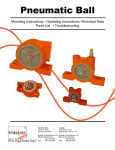
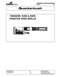
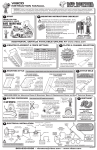
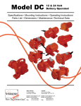
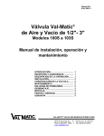
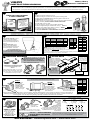
vibco
Heavy Duty
Electric Vibrators
instruction manual
WARNING: Failure to read and follow these installation instructions and safety precautions could result in personal injury, equipment damage,
shortened service life or unsatisfactory equipment performance. All information in this document is vital to the proper installation and operation of
the equipment. It is important that all personnel who will be coming in contact with this product thoroughly read and understand this manual.
1
start
2
THANK YOU FOR CHOOSING
A VIBCO VIBRATOR!
oDetermine vibrator placement on bin.
oDetermine length of channel iron and style of mounting plate.
oSelect method of STITCH welding mounting plate to channel iron.
oSTITCH weld channel iron to bin.
oAttach vibrator to mounting plate. Check the mounting plate for warping
& shim if necessary. DO NOT OVER TIGHTEN THE BOLTS.
oInstall safety chain or cable.
oConnect wiring for vibrator using the NEC Standards.
o Take a voltage reading at vibrator while running. VOLTS = o Take an amp reading while vibrator is running. AMPS = o Compare readings to standard values.
oFILL OUT WARRANTY CARD AND MAIL TO VIBCO!!!!
MENT OR
REPLACE
S
VER UNIT
CROSS O
L
A
M
R
E
H
T
REQUIRE AD
O
L
R
OVE
ION &
PROTECT IRST!
CK F
AMP CHE
NEW
INSTALLAT
ION
START
HERE!
mounting instructions checklist
ty
an
rr
wa
ADDITIONAL DETAILS AVAILABLE ONLINE AT www.vibco.com
3
vibrator placement
4
For coarse materials: mount
vibrator 1/3 of the distance
from the discharge opening to
the top of the sloped portion of
the bin.
For fine materials: mount
vibrator 1/4 of the distance
from the discharge to the top of
the sloped portion of the bin.
VIBRATOR
MNTNG PLATE
FORCE in LBS
THICKNESS
FACTOR
A
101 - 500
1/4" - 3/8"
3" x 4.1 lbs
3" x 5 lbs
2
501- 1200
1/2"
4" x 5.4 lbs
4" x 7.5 lbs
3
1201 - 3000
5/8"
6" x 8.2 lbs / 6" x 10.5 lbs
4
3001 - 5000
3/4" - 1"
6" x 8.2 lbs / 6" x 10.5 lbs
8" x 8.5 lbs / 8" x 11.5 lbs
5
BIN WALL FACTOR
THICKNESS
B
6
vibrator & mounting plate must be
mounted PERPENDICULAR TO CHANNEL
IRON, NOT PARALLEL. otherwise, it
will cause flexing & the vibrator
will overload & burn out.
STUDDED
A MOUNTING PLATE MUST BE USED
to ensure proper stability for the
vibrator.
Always start & stop welds 1 in. from ends
to prevent heat concentration. Then weld 2
to 3 inches, skip 1 to 2 inches and repeat
until the plate is securely mounted.
1/8" (10 ga.)
or less
6
1/8" - 1/4"
5
1/4" - 3/8"
4
3/8" - 1/2"
3
1/2" & up
2
1. Longer channel iron will not affect vibrator performance, but
total channel length should not exceed length of bin wall.
2. Percentages shown indicate % of bin wall height your channel iron should be
for shorter bins.
3. To match your vibrator on chart above, model number suffixes generally correspond to
pounds of force generated. For any questions, consult VIBCO.
mounting hardware
STANDARD
CHANNEL IRON SIZE
NO!
stitch weld
YES!
11
N/A
10
6 - 8 FT.
(80 - 90%)
9
5 - 7 FT.
(70 -80%)
8
4 - 6 FT.
(60 - 70%)
7
3 - 5 FT.
(50 - 60%)
6
2 - 4 FT.
(50 - 60%)
5
1 - 2 FT.
(50 - 60%)
4
N/A
STITCH WELDS
SHOULD START
& STOP 1” (2.5cm)
FROM BOTH ENDS
OF CHANNEL TO
PREVENT CRACKING
(TOP VIEW)
Be sure all welding
is done by a certified
welder. all standard
channel and plates
provided by vibco
are a36 steel, 304
stainless or
6061 aluminum.
DO NOT MOUNT
VIBRATOR
DIRECTLY
TO SURFACE OF BIN !!!
Always use mounting
plate & channel iron
USE
CH. IRON
LENGTH
FACTOR
A+B
NOTE:
FOR ALTERNATE MOUNTS
refer to full detail instruction manual
online at www.vibco.com or call 800-633-0032
5
plates & channel selection
STITCH
WELDS
SHOULD
BE 3” LONG
LEAVING
3” (7.5cm)
BETWEEN
EACH WELD
ALWAYS WELD
CHANNEL UNDER
PLATE AREA
(BOTTOM VIEW)
800-633-0032 for Mounting Plates & Brackets, Spare & Replacement Parts and 24/7 Technical Support
7
bolting procedure
Step 1
1
2
Place vibrator on
mounting plate,
then insert & tighten
2 Grade 5 bolts
on same end of
vibrator. See proper
torque values right.
NOTE: Shimming the feet is necessary to avoid strain on the shaft & bearings
that can cause high amperage draw & burn out the vibrator.
Step 2
SHIM
Now, look at feet on
other end of vibrator. If
a gap exists between
the mounting plate &
feet, welding warped the
mounting plate. Shim
space under feet.
MAX
GRADE 5
TORQUE
BOLT SIZE
ft-lbs
4
3
Step 3
After gap has been filled with
shim(s), insert & tighten the
other TWO Grade 5 bolts.
Now put vibrator in place. Make sure it is secured tightly. Retighten bolts after first 10 to 15 minutes of operation and check periodically to
maintain proper tightness. Damage to both bin and vibrator can occur if vibrator is not mounted securely. NOTE: no matter how thick the
mounting plate, it can still warp during welding, especially if VIBCO’s instructions are not followed.
8
restraint
ALWAYS INSTALL
SAFETY
CABLE or CHAIN
Mount one end to the
vibrator and the other to
the hopper or bin
above the vibrator
NEVER ATTACH TO THE
MOUNTING PLATE!
9
electrical installation
3 PHASE
Have vibrator
installed by a
qualified
electrician
SINGLE PHASE
OR
warranty will be
Plug it into a
VOID if vibrator is not
grounded circuit.
connected to proper overload protection.
For proper sized overload protection consult
NOTE: For rewiring for other than 115V on a single
a qualified electrician or contact a VIBCO
phase unit, refer to detailed manual or consult factory.
representative.
and then . . . TAKE AN AMPERAGE
READING WHILE THE VIBRATOR
IS RUNNING
1/4"
9
5/16"
18
3/8"
32
1/2"
78
5/8"
160
3/4"
260
1"
580
1-1/4"
1105
For other bolt grades,
please consult VIBCO.
Follow numbers on leads.
NOTE: Some wires may be color-coded as follows:
1 - blue
4 - yellow
7 - pink
2 - white
5 - dark gray
8 - red
3 - orange
6 - purple
9 - light gray
6
5
4
6
5
4
9
8
7
9
8
7
3
2
1
3
2
1
L3
L2
L1
L3
L2
L1
230 or 240 volt
460 or 480 volt
Operating amperage should not exceed the value listed on the vibrator label. If
it does, it is most likely due to faulty mounting. Check your mounting welds, and
re-tighten bolts if necessary. See TROUBLESHOOTING for more info.
800-633-0032 • [email protected] • www.vibco.com
REV136-12
vibco
Heavy Duty
Electric Vibrators
instruction manual
Maximum OPERATING
Temperature
WARNING: Failure to read and follow these installation instructions and safety precautions could
result in personal injury, equipment damage, shortened service life or unsatisfactory equipment
performance. All information in this document is vital to the proper installation and operation of
the equipment. It is important that all personnel who will be coming in contact with this product
thoroughly read and understand this manual.
10
lubrication
high Temperature
units consult factory!
Grease Specifications
Lubriko M21 general purpose grease
or equal Sodium Calcium based NLGI
grade 2 grease. Minimum temperature
range 0°- 225°F. Minimum viscosity
70 - 80 SUS (at 212°F).
MODEL #
INTERMITTENT
DUTY
CONTINUOUS
DUTY
2P-800, 2P-1700, 2P-2500,
2P-3500, 2P-4500, 2P-5500
Lubricate every
400-500 hours
Lubricate every
2 weeks
4P-1400, 4P-2000, 4P-3000,
4P-5000, 4P-10000
Lubricate every
1000-2000 hours
Lubricate every
4 weeks
6P-1000, 6P-1500,
6P-2500, 6P-5000
Lubricate every
1500-3000 hours
Lubricate every
6 weeks
8P-500, 8P-750,
8P-1250, 8P-2500
Lubricate every
3000-4000 hours
Lubricate every
8 weeks
Use 2.5 to 3 grams (two pumps
with standard manual grease gun).
Do not over grease!
11
Models 2P-75, 2P-100, 2P-150, 2P-200, 2P-450, 4P-350,
4P-700, 4P-1000, and 6P-500 are pre-lubricated for life.
changing output settings
To change the force:
1.Disconnect from power.
2.Remove both end covers.
MODELS: 2P-75, 100, 150, 200; 4P-350
3.Remove the cap screw that
holds the outer eccentric
to the inner eccentric and
turn the outer eccentric so
that the numbered hole
aligns with the threaded
hole in the inner eccentric.
NOTE: You must set both
CAP
CAP
CAP
SCREW
SCREW
SCREW ends of the vibrator to the
MAXIMUM
FACTORY
MINIMUM
same setting.
FORCE
SETTING
FORCE
4.
Replace the cap screw.
Intermittent Duty Only
Maximum Setting for
Optimum Setting for Long
Continuous Duty
Life of Vibrator
5.Replace both end covers.
NOTE: If you INCREASE force of vibrator, you MUST take a new amperage draw reading to ensure vibrator
is still operating within specified limits.
NOTE: Only run intermittently when set to higher than factory set output forces (maximum running
time of 30 min in any one hour period).
MODELS: 2P-450, 800, 1700, 2500; 4P-600, 700, 1000, 1400, 2000, 3000, 5000, 10000
6P - ALL MODELS; 8P- ALL MODELS
To adjust eccentric settings:
NOTE: These vibrators are set to Setting #3 (Factory Setting).
1.Remove both end covers from vibrator.
2.Loosen the bolt that holds the outer, labeled
eccentric to the shaft. NOTE: some models
have only one eccentric per side.
3.Turn the eccentric on the shaft to adjust force
output. Align the arrow on the shaft to the
desired setting. The higher the number, the
greater the force.
NOTE: You must set both ends of the
vibrator to the same setting.
4.Tighten eccentric bolts and reinstall end covers.
BOLT
12
Skin temperature of vibrator should not exceed
180o F (82o C). If it exceeds this,
consult VIBCO for alternate solutions.
troubleshooting
My Material STILL Isn’t Moving!
1. Did you put your vibrator in the right location? Did you mount
your vibrator properly?
2. Do you have the right vibrator for the job? Does it provide
enough force? Do you have the vibrator set to the maximum
force? (see left) Is it the right frequency? Still not sure? Call
VIBCO Technical Support at 800-633-0032.
The Vibrator won’t start!
1. Check power supply to unit. Are you getting the proper
voltage? Has the thermal overload protection tripped?
2. Check stator continuity, if “open” stator winding is burned or
has a short, replace stator. If unsure how to check continuity,
call VIBCO or consult a licensed electrician.
Vibrator stops running!
1. Check power supply to unit.
2. Has the thermal overload protection tripped? Single phase
units are supplied with overload switches. Three phase units
must be connected to three phase motor starters with proper
overload protection. If overload protection has tripped, wait a
minimum of two (2) minutes then reset by switching firmly off
and then on again.
3. Are you running the vibrator in a wet or wash down
environment? Consult VIBCO about wash down rated models.
4. Are you running the vibrator in a high temperature
environment? Consult VIBCO about high temp rated models.
Refer to full detail instructions for proper mounting in high
temp applications.
5. Are you running the vibrator continuously? All VIBCO heavy
duty models are rated for continuous duty but only at certain
eccentric settings. See diagrams to left for proper output force
settings for continuous duty.
NOTE: For best performance and vibrator life cycle, it
is best to run them intermittently. Consult VIBCO for
available timers.
6. Are you repeatedly stopping and starting the vibrator? This
can overload the vibrator. Use the following guidelines for
proper timing of starts and stops:
Single phase (2P-75, 100 & 150):
For run times of 10 seconds or less, use 1:7 ratio for run time
LEFT
RIGHT
Settings 1 - 3 are continuous duty rated
Settings 4 - 6 are intermittent duty rated only
For vibrators mounted in tandem (side to side, not end-to-end)
to produce linear motion on table & feeder applications:
To produce linear motion you must make sure vibrators rotate opposite from one another. Force output labels
should be opposite to one another when viewed from the same side (one increases clockwise, the other counterclockwise as in picture above). Follow instructions as above, & be sure you set both vibrators & both ends to the same
setting. Consult VIBCO for more details.
NOTE: If you INCREASE force of vibrator, you MUST take a new amperage draw reading to ensure vibrator is still
operating within specified limits.
NOTE: Only run intermittently when set to higher than factory set output forces (maximum running time of 30 min in
any one hour period).
vs. off time. (example: 5 seconds on to 35 seconds off). For
run times longer than 10 seconds, use 1:1 ratio.
Single phase (2P-200, 450, 800; 4P-350, 700, 1000, 1400; 6P-300, 500):
These are capacitor start models and rated for a MAXIMUM
of 30 starts per hour.
Three phase:
For run times of 10 seconds or less, use 1:7 ratio for run time
vs. off time. (example: 5 seconds on to 35 seconds off). For
run times longer than 10 seconds, any cycle is acceptable.
NOTE: Proper force for full hopper can be excessive
for empty or near empty hopper.
Warranty
All warranty claims must be submitted to VIBCO for approval prior to any repairs being done. Failure to do so will void any and all warranty coverage. All repairs will be
done at the VIBCO factory.
Errors, Shortages & Complaints
Complaints concerning goods received or errors should be made at once. Claims must be made within five days after receipt of goods. Clerical errors are subject to correction. Damage during shipping must be reported to the carrier, not VIBCO.
Returning Parts **
Parts should not be returned to VIBCO without prior authorization. Call VIBCO’s customer service department at 800-633-0032 (800-465-9709 in Canada) for a Return
Goods Authorization (RGA) number. A return authorization will be emailed or faxed to you. Use this as your packing slip. Return shipping must be prepaid. Material
returned may be subject to a 10% restocking fee. All returned shipments should clearly display your name, address and original invoice number to ensure proper credit.
** Orders for custom equipment built to customer’s specifications are not returnable.
Product Changes
VIBCO reserves the right to make changes in pattern, design or materials when deemed necessary, without
prior notice or obligation to make corresponding changes in previous models. To be sure of exact mounting
dimensions, it is recommended that you obtain a certified dimensional drawing from the factory.
Ordering Spare Parts
Parts can be ordered through authorized distributors or from VIBCO’s Spare Parts Department. The following
data should be provided when placing your spare parts order:
From label:
Model number of unit.
From spare parts list: Reference number, part number, description & quantity required.
Shipping instructions: Specify shipping point and method of shipping.
For custom mounting
applications or any
other questions:
800-633-0032
or
[email protected]
800-633-0032 • [email protected] • www.vibco.com
REV136-12