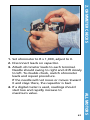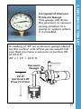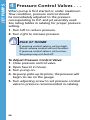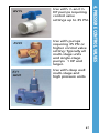
1
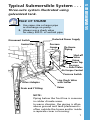
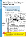
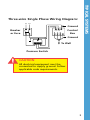
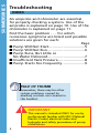
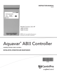
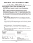
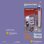
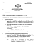
GSSINGLE
IT T
Residential Water Systems
1Ø Service Manual
• Submersible Pumps
• Jet Pumps
Goulds Pumps is a brand of ITT Corporation.
www.goulds.com
Engineered for life
TABLE OF CONTENTS
Table of Contents
This manual covers single phase 4" submersible pumps and jet pumps.
Submersibles: (Pages 1 – 35)
Page
Typical Systems....................................................... 1-3
Troubleshooting..................................................... 4-9
Amprobe Instructions.......................................... 10
Ohmmeter Instructions........................................ 11
A Capacitor Checkout.......................................... 12-13
B Relay Checkout.................................................. 14-16
C Overload Checkout.............................................. 17
D Voltage Checkout............................................. 18-19
E Electrical Short Checkout.................................. 20-21
F Motor Winding Resistance Checkout................. 22-23
G Cable Checkout................................................. 24-25
H Amperage Checkout......................................... 26-27
I Pressure Switch Adjustment............................... 28-29
J Pressure Tank Checkout...................................... 30-31
Submersible Pump Disassembly........................ 32-33
Submersible Pump Reassembly......................... 34-35
Jet Pumps: (Pages 36 – 71)
Typical Systems..................................................... 36-41
Troubleshooting................................................... 42-49
1 Voltage Checkout.............................................. 50-51
2 Amperage Checks............................................. 52-53
Ohmmeter Checks............................................ 54-63
Wiring Diagrams............................................... 60-61
3 Checking Suction Lift........................................ 64-65
4 Pressure Control Valves..................................... 66-67
Jet Pump Disassembly....................................... 68-69
Jet Pump Reassembly........................................ 70-71
Goulds Pumps, CentriPro and the ITT Engineered Blocks symbol
are registered trademarks and tradenames of ITT Corporation.
Three-wire system illustrated using
galvanized tank.
RULE OF THUMB
1.
2.
Use same size or larger pipe as discharge on pump.
Always use a check valve for every 200 ft. of vertical pipe.
Protected Power Supply
Disconnect Switch
Control Box
Pressure
Gauge
To House
Piping
Shut-off
Valve
Union
Drain Tap
Pressure
Relief Valve
Air Escape Control
Pressure Switch
Pitless Adapter
Drain and Y Fitting
Line Check Valve
with Snifter
Union
NOTE:
Piping below the frost line is common
in colder climate areas.
In warm climates, the piping is often
above ground and tank placement is
often outside the house and/or inside a separate cover or housing.
1
SUBMERSIBLES
Typical Submersible System . . .
SUBMERSIBLES
Typical Submersible System . . .
Two-wire system illustrated; using
diaphragm type tank.
RULE OF THUMB
1.
2.
Use same size or larger pipe as discharge on pump.
Always use a check valve for every 200 ft. of vertical pipe.
To House Piping
Protected Power Supply
Disconnect
Switch
Shut-off
Valve
Union
Pressure
Switch
Pressure
Relief Valve
Drain
Tap
Pitless
Adapter ➀
Check
Valve ➀
Frost Level
➀
➁
Tank Tee
Check Valve ➁
On installations with a pitless adapter the top check valve should be below the pitless, not at the tank, as the discharge line should be pressurized back to the pitless.
On installations with well seals or well pits it is allowable to locate the top check valve near the tank.
CAUTION
2
All electrical equipment must be connected
to supply ground. Follow applicable code
requirements.
TYPICAL SYSTEMS
Three-wire Single Phase Wiring Diagram:
L1 L2
Ground
Breaker
or Fuse
Control
Box
L1 L2
B Y R
Ground
To Well
Pressure Switch
CAUTION
All electrical equipment must be
connected to supply ground. Follow
applicable code requirements.
3
SUBMERSIBLES
Troubleshooting
INDEX
An amprobe and ohmmeter are essential
for properly checking a system. Use of the
amprobe is explained on page 10. Use of the
ohmmeter is explained on page 11.
Find the basic problem . . . for which
numerous symptoms are listed and possible
solutions are given for each:
Page
■ Pump Will Not Start.................................5
■ Pump Will Not Run..................................6
■ Pump Runs, But Little or
No Water Delivered..................................7
■ Insufficient Tank Pressure.........................8
■ Pump Starts Too Frequently.....................9
RULE OF THUMB
Remember, there may be other
system problems caused by
auxiliary controls not covered in
this booklet.
IMPORTANT
This manual is intended ONLY for use by
professionals familiar with NEC (National
Electric Codes) electrical codes and
hydraulic and safety procedures of pump
installations.
4
Troubleshooting
Pump Will Not Start . . .
If fuses and overload check okay . . .
PROBLEM:
ANSWER:
1. No power or See D
incorrect voltage
2. Defective pressure Inspect points and switch
replace switch if necessary.
3. Loose connection See E, F, G in control box, cable or motor.
5
TROUBLESHOOTING
Letters and Numbers in chart, ex. “See A” refer to
sections in the Manual. Submersible sections use
letters and Jet sections are numbered.
SUBMERSIBLES
Troubleshooting
Pump Will Not Run . . .
If motor overload trips or fuses blow . . .
PROBLEM:
ANSWER:
1.Improper size fuses
Replace with correct.
2.Wrong control box
Replace with correct.
3.Incorrect voltage
See D
4.Defective control box See A, B, C 5.Loose connections See E in control box, Condition causes cable or motor
improper resistance readings.
6.Cable insulation See G
damaged or splice Condition causes may be open or improper resistance shorted
readings.
7.Defective pressure Inspect points and/
switch or or replace switch if plugged tubing
necessary.
8.Control box in hot Temperature not to
environment
exceed 122°F (50°C).
9.Pump bound by Pull pump and
abrasives
clean. See H
Condition causes high amperage.
6
Pump Runs, But . . .
Little or no water delivered . . .
PROBLEM:
ANSWER:
1.Line check valve stuck Replace if defective.
or installed backwards
2.Connections loose See wiring diagram or misconnected in in control box.
control box
3.Incorrect voltage
See D
4.Pump not submerged Check water level in well.
5.Leak in piping system Replace if necessary.
6.Worn pump
Repair or replace water-end.
7.Worn motor
Replace motor.
8.Suction screen or Pull pump and
impeller clogged
clean.
9.Broken pump shaft Replace.
or coupling
7
TROUBLESHOOTING
Troubleshooting
SUBMERSIBLES
Troubleshooting
Insufficient Tank Pressure . . .
PROBLEM:
1. Improper pressure switch setting
2. Incorrect voltage
3. Excessive pump wear
4. Leaks in piping system
8
ANSWER:
See I
See D
Repair or replace.
Repair or replace.
Repair or replace.
Pump Starts Too Frequently . . .
PROBLEM:
ANSWER:
1.Waterlogged tank
a. Galvanized
Check tank for leaks. Check drain and “Y” fittings, snifter valve for proper operation.
b. Captive air type
See J
2.Check valve Replace if necessary.
stuck open
3.Improper pressure See I
switch setting
4.Leaks in Repair or replace
piping system
5.Pressure tank improperly sized
RULE OF
THUMB
Must be sized to
allow a minimum
run time per cycle
as follows:
1
⁄3 – 1½ HP = 1 minute run time
2 HP & larger = 2 minute run time
9
TROUBLESHOOTING
Troubleshooting
SUBMERSIBLES
Amprobe Instructions
The Amprobe is a multi-range, combination
ammeter and voltmeter.
Voltmeter Scales: 150 VOLTS 600 VOLTS
Ammeter Scales:
5 AMPS
40 AMPS
15 AMPS
100 AMPS
1.When used as an ammeter, the tongs are placed around the wire being measured with the rotary scale on the 100 amp range. Then rotate the scale back to the smaller ranges until an exact reading is indicated.
2.When used as a voltmeter, the two leads are clipped into the bottom of the instrument with the rotary scale on the 600 volt range. If the reading is less than 150 volts, rotate the scale to the 150 volt range to get a more exact reading.
10
The Ohmmeter is used for measuring the
electrical resistance of a wire circuit. The unit of
measurement is called an Ohm.
1.The knob at the bottom of the Ohmmeter is adjustable through six ranges:
RX1
= R x 1
If your ohmmeter
RX10
= R x 10
is digital readout
RX100
= R x 100
type, refer to the
RX1000 = R x 1,000
instructions that
RX10K
= R x 10,000
came with it.
RX100K = R x 100,000
2. The round center knob is for the purpose of adjusting the instrument to zero (0) after clipping the two ohmmeter leads together. This must be done every time the range selection is changed.
CAUTION
Use Ohmmeter only with power off.
11
AMPROBE/OHMMETER INSTRUCTIONS
Ohmmeter Instructions
SUBMERSIBLES
A
Capacitor Checkout
Capacitor with Ohmmeter
CAUTION
Discharge the capacitor before making
this check. (A screwdriver can be used to
make contact between capacitor’s posts.)
1.Disconnect leads to capacitor post.
2.Setting: R x 1,000
3.Connect ohmmeter leads to capacitor posts.
4.Reading: Pointer should swing toward zero, then back toward infinity.
12
Capacitor Checkout
A. CAPACITOR CHECKOUT
A
“Quick-Disconnect” Control Box
RULE OF THUMB
To recheck, reverse the
OHMMETER LEADS.
13
SUBMERSIBLES
B
Relay Checkout Voltage Relay
Control Boxes (CentriPro or F.E.)
Checking Relay with Ohmmeter
A. Voltage Relay ½ – 1 HP CP - QD; 1 – 15 HP CSCR Control
Boxes
Step 1, Coil Test
1. Meter setting: R x 1,000.
2. Connections: #2 & #5.
3. Correct meter readings:
For 115 Volt Boxes:
.7 – 1.8 (700 to 1,800 ohms).
For 230 Volt Boxes
4.5 – 7.0 (4,500 to 7,000 ohms).
Step 2, Contact Test
1. Meter setting: R x 1.
2. Connections: #1 & #2.
3. Correct meter reading: Zero for all models.
14
C. F.E. Black Solid State Switch 1
⁄3 – 1 HP QD Control Boxes
Used from 1985 until 1994
Step 1, Triac Test
Step 2, Coil Test
1. Meter setting: 1. Meter setting: R x 1,000.
R x 1.
2. Connections: 2. Connections: R (Start) terminal Y (Common) and orange lead and L2.
on start switch.
3. Correct meter 3. Correct meter reading: Zero reading: Infinity ohms for all for all models.
models.
15
B. SINGLE PHASE CONTROL BOX RELAY CHECKOUT
B. F.E. Blue Relay - Solid State 1
⁄3 – 1 HP QD Control Boxes Used from 1994 until present time:
Step 1, Triac Test
Step 2, Coil Test
1.Meter setting: 1. Meter setting: R x 1,000.
R x 1.
2.Connections: Cap 2. Connections: and B terminal.
L1 and B.
3.Correct meter 3. Correct meter reading: Infinity reading: Zero for all models.
ohms for all models.
SUBMERSIBLES
B
Relay Checkout Continued
Contactor Checkout Checkout procedure for magnetic and other
Contactors
Contactor Coil Test
(Disconnect lead from one side of coil)
1. Meter setting: R X 100
2. Connections: Coil terminals
3. Correct meter reading: 180 to 1,400 ohms
Contactor Contact Test
1. Meter Setting: R X 1
2. Connections: L1 & T1 or L2 & T2
3. Manually close contacts
4. Correct meter reading: Zero ohms
Additional information on troubleshooting and replacement parts for Single Phase Control
Boxes is available in the ITT, MAID; Motor
Application, Installation Manual and in the F.E.
AIM. It is available online at www.goulds.com
and www.franklin-electric.com.
16
Overload Checkout . . .
For 1½ HP (and Larger) Control Box . . .
1.Set Ohmmeter at “R x 1”
2.Connect the Ohmmeter leads to Terminal #1 and #3 on each Overload Protector.
3.Reading should be not more than 0.5 Ohms maximum on the scale.
CSCR or Mag. Contactor Control Box
17
C. CONTROL BOX OVERLOAD CHECKOUT
C
SUBMERSIBLES
D
Voltage Checkout
To Check Voltage with “Q.D.” Type Control
Box
1.Remove cover to break all motor connections.
CAUTION
L1 and L2 are still connected to power.
2.To check VOLTAGE: Use voltmeter on L1 and L2 as shown.
3.When checking voltage, all other major electrical appliances (that could be in use at the same time) should be running.
4.If readings are not within the limits (see chart), call your power supplier.
18
Voltage Limits
Measured Volts
Nameplate ▼
Min.
Max.
115V 1ø
105
125
208V 1ø
188
228
230V 1ø
210
250
Voltage Checkout
D. VOLTAGE CHECKOUT
D
19
SUBMERSIBLES
E
Electrical Short Checkout . . .
Measuring Insulation Resistance
1.Set the scale lever to R x 100K and adjust to 0.
CAUTION
Open (turn off) master breaker and
disconnect all leads from control box or
pressure switch (Q-D type control, remove lid) to avoid damage to meter or electric
shock hazard.
2.Connect an ohmmeter lead to any one of the motor leads and the other to the metal drop pipe. If the drop pipe is plastic, connect the ohmmeter lead to the metal well casing or ground wire.
OHMS
R x 100K
Drop
Cable
with
Ground
Wire
20
R x 100
R x 10
Rx1
ZERO
OHMS
R x 1000
R x 10K
R x 100K
Insulation resistance does not vary with rating. All motors of all
HP, voltage and phase rating have similar values of insulation
resistance.
Condition of Motor and Leads
Ohm Megohm
Value
Value
A new motor (without drop cable).
20,000,000
20.0
(or more)
A used motor which can be 10,000,000
10.0
reinstalled in the well.
(or more)
Motor in Well. Ohm readings are 2,000,000
2.0
for drop cable plus motor.
(or more)
A new motor in the well.
A motor in the well in reasonably 500,000 – good condition.
2,000,000 0.5 – 2.0
A motor which may have been damaged
20,000 – 0.02 – 0.5
by lightning or with damaged leads. Do 500,000
not pull the pump for this reason.
A motor which definitely has been 10,000 –
0.01 –
damaged or with damaged cable. The 20,000
0.02
pump should be pulled and repairs made to the cable or the motor replaced. The motor will not fail for this reason alone, but it will probably not operate for long.
A motor which has failed or with
Less than 0 – 0.01
completely destroyed cable insulation. The
10,000
pump must be pulled and the cable repaired or the motor replaced.
What It Means
1. If the ohm value is normal, the motor windings are not grounded and the cable insulation is not damaged.
2.
If the ohm value is below normal, either the windings are grounded or the cable insulation is damaged. Check the cable at the well seal as the insulation is sometimes damaged by being pinched.
Winding Resistance Measuring
When measured as shown on page 22, motor resistance only
should fall within the values in Table 3, page 23. When measured
through the drop cable, the size and length of the cable must be
known and the correct cable resistance from Table 2 subtracted
from the ohmmeter reading to get the winding resistance for
comparison with Table 3.
21
E. ELECTRICAL SHORT CHECKOUT
Table 1 Normal Ohm and Megohm Values (Insulation Resistance) Between All Leads and Ground
SUBMERSIBLES
F
Motor Winding Resistance
Checkout . . .
Measuring Winding Resistance
1.Set the scale lever to R x 1 for values under 10 ohms. For values over 10 ohms, set the scale lever to R x 10. Zero balance the ohmmeter as described earlier on page 11.
CAUTION
Open master breaker and disconnect all leads from control box to pressure switch (Q-D type control, remove lid) to avoid
damage to meter or electric shock hazard.
2.Connect the ohmmeter leads as shown below.
Table 2 Cable Resistance – Copper
Size Cable
14
12
10
8
6
4
2
DC Resistance of Cable per 100 Foot Length Ohms per Pair of Leads
.544
.338
.214
.135
.082
.052
.032
If aluminum cable
is used the readings
will be higher. Divide
the ohm readings
on this chart by 0.61
to determine the
actual resistance of
aluminum cable.
22
Ground
Wire
OHMS
R x 100
R x 10
Rx1
Motor
Leads
ZERO
OHMS
R x 1000
R x 10K
R x 100K
Rx1
or
R x 10
Single Phase Motors – Winding Resistance Motor Only (Ohms)
4" Motors
CentriPro Franklin Electric
Winding
KVA
Winding
KVA
Type
HP
Volts
Resistance Code Resistance Code
½
115
1.3-1.8
K
1.0-1.3
R
½
230
4.5-5.2
K
4.2-5.2
R
2-Wire
¾
230
3.0-4.8
J
3.0-3.6
N
(PSC)
1
230
4.2-5.2
F
2.2-2.7
N
1½
230
1.9-2.3
H
1.5-1.9
M
4" Motors
CentriPro
Franklin Electric
Resistance
Resistance
KVA
KVA
Type HP Volts Main
Start Code Main Start Code
(B-Y)
(R-Y)
(B-Y) (R-Y)
3-Wire
½
.9-1.6 5.7-7.0
N 1.0-1.3 4.1-5.1 M
4.2-4.9 17.4-18.7 M 4.2-5.216.7-20.5 M
w/Q.D. ½
115
Cap. ¾
2.6-3.6 11.8-13
L 3.0-3.610.7-13.1 M
Start 1 2.2-3.2 11.3-12.3 L 2.2-2.7 9.9-12.1 L
J 1.7-2.2 8.0-9.7
J
3-Wire 1½ 1.6-2.3 7.9-8.7
w/CSCR 2
1.6-2.2 10.8-12.0 G 1.8-2.3 5.8-7.2
G
230
(CR)
G 1.0-1.5 3.5-4.4
H
Control 3 1.1-1.4 2.0-2.5
5 .62-.76 1.36-1.66 E .68-1.0 1.8-2.2
F
Box
6" Motors
CentriProFranklin Electric
Resistance KVA
Resistance
KVA
Type HP Volts
R - Y B - Y R - B Code (B-Y)
(R-Y) Code
5 2.1720.5122.627 G .55-.68 1.3-1.7 E
6"
F
Single 7.5 230 1.401 0.4 1.774 F .36-.50 .88-1.1
Phase 10 1.0520.316 1.31 E .27-.33 .80-.99 E
15 0.678 0.23 0.85 D .17-.22 .68-.93 E
RULE OF THUMB
Add resistance of drop cable when checking
pump in well. See Table 2 page 22.
What it Means
1.
2.
3.
4.
If all ohm values are normal, the motor windings are neither shorted nor open, and the cable colors are correct.
If any one ohm value is less than normal, the motor is shorted.
If any one ohm value is greater than normal, the winding or the cable is open or there is a poor cable joint or connection.
If some ohm values are greater than normal and some less, the leads are mixed.
23
F. MOTOR WINDING RESISTANCE CHECKOUT
Table 3 Motor Resistance
SUBMERSIBLES
G
Cable Checkout . . .
Checking Cable and Splice
1.Submerge cable and splice in steel barrel of water with both ends out of water.
2.Set ohmmeter selector on RX100K and adjust needle to zero (0) by clipping ohmmeter leads together.
3.After adjusting ohmmeter, clip one ohmmeter lead to barrel and the other to each cable lead individually, as shown.
4.If the needle deflects to zero (0) on any of the cable leads, pull the splice up out of the water. If the needle falls back to (∞) (no reading) the leak is in the splice.
5.If leak is not in the splice, pull the cable out of the water slowly until needle falls back to (∞) (no reading). When the needle falls back, the leak is at that point.
6.If the cable or splice is bad, it should be repaired or replaced.
24
G. CABLE CHECKOUT
Checking Cable and Splice Test
OHMS
Ohmmeter
Set at R x 100K
R x 100
R x 10
Rx1
ZERO
OHMS
R x 1000
R x 10K
R x 100K
Attach this lead
to Metal Tank
25
SUBMERSIBLES
H
Amperage Checkout . . .
Service Factor Amps w/QD (½ - 1 HP) or CSCR (1.5 HP & larger) Control Boxes
4"
CP
F.E.
CP
F.E.
1Ø
3-Wire
3-Wire
2-Wire2-Wire
HP Volts Yel Black Red Yel Black Red Black Black
½ 115 12.6 12.6 0 12.0 12.0 0 9.5 12.0
½
6.3 6.3 0 6.0 6.0 0 4.7
6.0
¾
8.3 8.3 0 8.0 8.0 0 6.4
8.0
1
9.7 9.7 0 9.8 9.8 0 9.1
9.8
1½ 230 11.1 11.0 1.3 11.5 11.0 1.3 11.0 13.1
2 12.2 11.7 2.6 13.2 11.9 2.6
3 16.5 13.9 5.6 17.0 12.6 6.0
N/A
5 27.0 22.0 10.027.5 19.1 10.8
Service Factor Amps w/Magnetic Contactor Control Boxes
6"
Single Phase CentriPro 3-Wire Franklin Elec 3-Wire
HP Volts Yel Black Red
Yel Black Red
5
27.5 N/A
N/A 27.5 17.4 10.5
7.5
41.0 N/A
N/A 42.1 40.5 5.4
230
10
58.0 N/A
N/A 51.0 47.5 8.9
15
85.0 N/A
N/A 75.0 62.5 16.9
26
H. AMPERAGE CHECKOUT
Control Box With Cover Attached
Control Box
With Cover Attached
Ground
To Power
Supply
Amprobe
Meter set on
Ampere Scale
27
SUBMERSIBLES
I
Pressure Switch
Adjustment Checkout . . .
CentriPro and Square D
AS3
AS4
Adjust in Proper Sequence:
1.CUT-IN: Turn range nut (big Spring) down for higher cut-in pressure, or up for lower cut-in.
2.CUT-OUT: Turn differential nut (small spring) down for high cut-out pressure, or up for lower cut-out.
CAUTION
To avoid damage, do not exceed maximum
allowable system pressure. Check switch
operation after resetting. Max. Square D
pressure 65 PSI, Max. CentriPro pressure 80 PSI.
28
I. PRESSURE SWITCH ADJUSTMENT
FURNAS
1.MAIN SPRING ADJUSTMENT: Turn clockwise to increase both Cut-Out and Cut-In pressure. (2 PSI/turn).
2.DIFFERENTIAL ADJUSTMENT: Turn differential nut clockwise to increase Cut-Out pressure without affecting Cut-In (3 PSI/turn).
CAUTION
(FURNAS)
To avoid damage, do not exceed maximum
allowable system pressure. Check switch
operation after resetting. Maximum pressure
80 PSI.
29
SUBMERSIBLES
J
Pressure Tank Checkout Procedure . . .
1.To check: Shut off power supply and drain system to “0” pressure.
2.Air pre-charge in tank should be 2 psi less than the cut-in pressure of the pressure switch.
Example: If pressure switch setting is 30-50 psi, tank should be pre-charged with 28 lbs. air.
3.If water at valve, replace tank.
RULE OF THUMB
Improper tank sizing may cause motor damage.
½ to 1½ HP pumps – Tank draw down
should be equal to the pump capacity in GPM
or greater.
Example: ¾ HP pump; capacity 12 GPM;
pressure switch setting 30/50 PSI; correct
tank – V140.
2 HP and larger pumps – tank drawdown should be double the pump capacity in GPM.
Example: 3 HP pump; capacity 30 GPM;
pressure switch setting 40/60 PSI; correct tank
selection: 2 – V350 tanks.
30
J. PRESSURE TANK CHECKOUT PROCEDURE
Shown with base extension
31
SUBMERSIBLES
Repair or Replace – Some Considerations – While our pumps are designed for ease of repair it is
important to compare the cost of repair versus the
cost of water end replacement. Replacing typical wear
parts such as impellers and diffusers is a cost effective
choice. However, if the outside metal parts such as the
casing, motor adapter and discharge head all require
replacement due to extremely harsh water it may be
less expensive to simply purchase a complete new
water end. A new casing or discharge head will require
drilling and tapping for two new cable guard holes.
Pump Disassembly for Typical 4" Submersible Pumps...
1. Remove 4 cable guard screws and remove cable guard.
2. Reinstall top 2 screws so that discharge head and casing may be removed as one piece.
3.
32
Using two pipe wrenches or a vice and pipe wrench, hold the motor adapter and turn the discharge head/
casing assembly clockwise (it has left-hand threads) to loosen the assembly.
33
PUMP DISASSEMBLY
4. Remove the casing assembly to expose the stages.
5. Remove the klip ring from the top of the shaft, this will allow you to remove the stages from the shaft. Note that on units which have operated in sandy water it may be hard to disassemble the stages.
6. The complete stages should be removed one at a time, disassembled and inspected. Replace worn parts as needed.
7. On most models the shaft and coupling assembly is replaceable without removing the motor adapter. Lift the shaft off and inspect the coupling and motor splines for excessive wear.
8. If motor replacement is necessary, remove the 4 nuts from the motor studs and separate the motor and motor adapter. If motor is OK, leave assembly intact.
9. The shaft sleeve is now part of the shaft/coupling assembly and will not have to be ordered as a replacement part. Shaft couplings are not available alone as they are a pressed part. Replace the entire shaft/coupling assembly if either shows wear.
10. We use several check valve styles. Some are built-in and some screw in from the top (outside) of the discharge head. Replace as necessary. Replacement of a “GS” check valve will require separation of the discharge head and casing as it installs from inside the discharge head. You may also replace it using a standard screw-in line type check valve.
SUBMERSIBLES
Pump Reassembly . . .
1.
2.
3.
4.
5.
6.
34
Clean all parts including the strainer. Replace basket type internal strainer now.
Place shaft and coupling assembly (and spacer where used) onto motor spline.
Reattach the motor adapter to the motor. Tighten the nuts in an alternating pattern.
Place straight edge across the rim of motor adapter. If it fails to touch the shaft sleeve, add one or more .010" shims (repair part No. 7K155) until they are either flush with motor adapter or slightly high, never low.
Install first stage bowl, first stage impeller, and diffuser.
Stack-up of the impeller hubs is checked by straight edge. Install succeeding stages in the same manner as the first. Check stack-up at least every second or third stage. If straight edge laid across the diffuser face fails to contact the impeller hub, a shim should be added (underneath the impeller). This will keep the bottom of the impeller from dragging on the bowl. Longer units have one intermediate bearing spider and sleeve, which should be placed to divide the stages evenly.
35
PUMP REASSEMBLY
7. When all stages are in place, replace klip ring on shaft.
8. Check upper bearing for wear and replace if loose on shaft. Replace bearing spider on stack.
9. Replace casing/discharge head assembly, turning counterclockwise (left-hand threads). Turn it all the way down so that the casing bottoms against the flange on the motor adapter.
10. Using a pipe wrench on the motor adapter and one on the discharge head, tighten to approximately 85 lbs/ft. This will be approximately 1⁄8 to ¼ turn from the hand tight position.
11. Remove the upper cable guard screws and replace the cable guard using all 4 screws. The cable guard should be straight up and down if the casing is properly tightened.
12. If you installed a new casing or discharge head they will have to be drilled and tapped to provide holes for the cable guard screws. Use a 9⁄64" drill and an 8-32 NC tap.
13. Replace the external wrap around strainer where used. New part number is 7K2242.
JET PUMPS
Jet Pumps . . .
Since these are the basic types that have
been used for many years, the vast majority
of jet pump service work will be on these
types . . .
Horizontal Jet
J+
36
JET PUMPS
Vertical Jet
SJ
37
JET PUMPS
Typical Jet Pump System . . .
Shallow Well
System illustrated is a Convertible jet pump
with a shallow well adapter and a pressure
tank.
RULES OF THUMB
• All jet pumps should be located at the
highest point in the suction side of the
system.
• (Distance from well head to pump) If offset
is greater than 20' . . . increase horizontal
pipes by one size each.
• Never use pipes smaller than the pump
suction tappings.
38
TYPICAL JET PUMP SYSTEMS
39
JET PUMPS
Typical Jet Pump System . . .
Deep Well
Packer and twin pipe systems
40
TYPICAL JET PUMP SYSTEMS
Improper Installations
• Trap air
• Hard to prime
TRAPS AIR
Proper Installations
• Easy to prime
41
JET PUMPS
Troubleshooting
INDEX
An amprobe, ohmmeter and vacuum pressure
gauge are essential for properly checking a
system. Use of the amprobe is explained on
page 10. Use of the ohmmeter is explained
on page 11. Use of the compound vacuum
pressure gauge is explained on page 66.
Find the basic problem . . . for which numerous
symptoms are listed and possible solutions are
given for each:
Page
■ Pump Will Not Run................................... 43
■ Pump Runs, But Little or No Water
Delivered.............................................. 44-45
■ Pump Starts and Stops Too Often....... 46-47
■ Insufficient Tank Pressure......................... 48
■ Switch Does Not Cut Out......................... 49
RULE OF THUMB
Remember there may be other system
problems caused by auxiliary controls not
covered in this booklet.
42
Pump Will Not Run . . .
PROBLEM:
1. Blown fuse or power
turned off
2. Broken or loose
wiring connections.
3. Motor overload
protection contacts open.
a. Improper voltage.
b. Pump bound mechanically – will not turn freely.
4. Pressure switch faulty
or out of adjustment.
5. Tubing or fittings on pressure switch plugged.
6. Faulty motor.
ANSWER:
Replace fuse – close all switches.
Examine all wiring and repair any bad connections.
Overload contacts will close automatically in a short time.
See 1 Volt Ammeter
Remove motor end cap, turn motor shaft by hand. Unit should rotate freely.
Adjust or replace switch. See I.
Remove switch tubing and/or all fittings and clean.
See 2
43
TROUBLESHOOTING
Troubleshooting
JET PUMPS
Troubleshooting
Pump Runs But . . .
Little or no water delivered . . .
PROBLEM:
ANSWER:
1. Pump or pipes not Fill pump completely primed.
completely with water through priming opening (reprime pump).
a. Deep Well system Control valve must be set properly or system will not pump. See 4
2. Foot valve or end of a. Shallow Well suction pipe either not system Install submerged or buried. vacuum gauge See 3
b. Deep Well system Physically check well conditions.
Foot valve in well or Replace foot valve if line check valve stuck necessary. (Very closed.
high vacuum, 22 inches or more, see 3.
3. Leaks on suction side Pressurize system
of pump. (Very
and inspect.
common problem.)
44
Pump Runs But . . .
PROBLEM:
4.Jet assembly plugged.
5.Punctured diaphragm in air control. Galvanized tanks.
6.Original installation, incorrect nozzle or diffuser combination.
ANSWER:
A. Shallow Well system Clean if necessary. (Insert wire through ½" plug in shallow well adapter.)
b. Deep Well system Pull jet assembly and clean.
Disconnect the
tubing and plug the connection in pump. If this corrects the trouble, the air control must be replaced.
Check rating in product catalog.
45
TROUBLESHOOTING
Troubleshooting
JET PUMPS
Troubleshooting
Pump Runs But . . .
Pump starts and stops too often . . .
POSSIBLE CAUSE:
ANSWER:
1.Leaks in piping system. Pressurize piping system and inspect. Repair or replace.
2.Faulty pressure switch. Check contact points. Adjust or replace switch. See I
3.Waterlogged Pumps using Brady galvanized tank, control: Test by faulty air control.
holding your ear on air control. If control is operating, air can be heard passing from control into tank when pump stops. If no air movement is heard, air control should be replaced.
4.Leaking tank or Use soapy water to air valve.
find leaks. Repair or replace.
46
Pump Runs But . . .
POSSIBLE CAUSE:
ANSWER:
5.Not enough suction Throttle suction line lift on shallow well with partially closed system – water flows valve.
into pump (flooded suction).
6.Insufficient vacuum or Pump requires
vacuum does not exist minimum 3" for long enough time vacuum for to operate air control. 15 seconds. 7.Improper air change See J in
in captive air tank.
submersible section.
8.Tank too small Replace with for pump.
proper size storage tank.
47
TROUBLESHOOTING
Troubleshooting
JET PUMPS
Troubleshooting
Pump Runs But . . .
Pumps water, but does not develop 40 lbs.
tank pressure. . .
PROBLEM:
ANSWER:
1.Leaks in well piping Pressurize piping or discharge pipe.
system and inspect.
2.Jet or screen on foot Clean if necessary.
valve partially plugged.
3.Improper pressure See 4
control valve setting (deep well only).
4.Suction lift too high Use vacuum gauge
for shallow well on shallow well
system.
systems. Vacuum should not exceed 22 inches at sea level.
a. Jet set too deep for On deep well system deep well system.
check ratings tables in catalog for maximum jet depth.
5. Faulty air charger.
Disconnect the tubing and plug the hole. If this corrects the trouble, the air control must be replaced.
6.Worn impeller hub Replace if necessary. and/or guide vane Clearance should not
bore.
exceed .012 on a side or .025 diametrically.
7.Overpumping the well. Throttle a valve on the pump suction – do not exceed 22" Hg.
48
Pump Runs But . . .
Pump develops 40 lbs. pressure, but switch
does not cut out . . .
PROBLEM:
ANSWER:
1.Pressure switch See I in incorrectly set.
submersible section.
2.Tubing or fittings Remove switch between switch and tubing and/or all pump plugged.
fittings and clean.
3.Faulty switch or Replace if necessary.
corroded contact points.
49
TROUBLESHOOTING
Troubleshooting
JET PUMPS
1
How to Use Volt-Ammeter
For Voltage Check
CAUTION
Power is ON during voltage checking.
1.Attach leads to volt-ammeter and select proper voltage scale for voltage to be tested.
2.Place leads in A position to test for presence of incoming voltage.
• Voltage should be within + 10% of the design voltage specified on the motor nameplate in A, B and C test positions.
3.With disconnect switch in ON position, move leads to B position and test voltage flow through fuse(s).
4.The C position tests voltage at pressure switch terminals. The voltage should be within limits with the motor operating.
Voltage Limits
Nameplate ▼
Measured Volts
Min.
Max.
115V 1ø
105
125
208V 1ø
188
228
230V 1ø
210
250
50
1. HOW TO USE VOLT AMMETER
51
JET PUMPS
2
How to Check Amperage
1.If attached, remove leads from volt-
ammeter. Select lowest reading amperage scale according to motor nameplate rating.
2.With disconnect switch in OFF position, clamp instrument around one incoming lead at pressure switch.
•Turn switch ON and observe amperage as motor runs. With proper voltage, reading should not exceed the MAXIMUM LOAD AMPERAGE of motor.
•Excessive amps means an overloaded condition or incorrect voltage applied. Problem could also be in motor.
•Take readings with pump running at
normal system pressure. At open discharge (zero pressure) the pump may exceed maximum amps due to no discharge head.
52
2. HOW TO CHECK AMPERAGE AT PRESSURE SWITCH
CAUTION
Power is ON during amperage testing.
53
JET PUMPS
2
Ohmmeter Checks . . .
CAUTION
Use ohmmeter only with POWER OFF.
Power supply OFF. Disconnect motor leads (L1 and L2). On dual-voltage motors, motor
must be wired 230V for the checks listed
below and illustrated on the page indicated
for each check. Rewire for 230V if necessary.
CHECK:
Page
a.Ground..................................................... 55
b.Winding Continuity.............................56-57
c. Contact Points (Switch).......................58-59
d.Overload Protector..............................60-61
e.Capacitor.............................................62-63
54
Ground Check . . .
CAUTION
Disconnect Power Source before checking.
a.Set ohmmeter to R x 1,000.
b.Attach one probe to ground screw and touch other probe to all terminals on terminal board, switch, capacitor and protector – any ohmmeter reading indicates ground.
If digital meter is used, the reading should be at least one megohm.
c. If grounded, check all external leads for cuts, breaks, frayed wires, etc. Replace damaged leads and recheck for grounds and proper lead routings. Make sure replaced leads are not pinched between canopy and end bell.
If ground is in stator, replacement of motor is recommended.
55
2. OHMMETER CHECKS
a
JET PUMPS
2
Ohmmeter Checks . . .
b Winding Continuity . . .
CAUTION
Disconnect Power Source before checking.
1.Terminal board connected for 230 V.
2.Set ohmmeter to R x 1, adjust to 0.
3.Slip a heavy piece of paper between motor switch points, discharge the capacitor and take the following ohm readings:
a.Resistance between L1 and A must be the same as between A and yellow.
b.Yellow to red (winding side of switch) must be the same as L1 to same red terminal.
OVERLOAD PROTECTOR
GOVERNOR
115/230 VOLT
VOLTAGE SELECTOR SWITCH
START
CAPACITOR
PRESSURE SWITCH
WIRING TERMINAL BOARD
START SWITCH
L1 = Blue wire
L2 = White wire
A = Purple wire
56
Old Style (Brown) Terminal Board Wiring.
A.O. SMITH MOTOR WIRING
115 VOLT
230 VOLT
Black (from motor) Black (from motor)
on L1
on A
Black/White (Black tracer from overload) on A
Black/White (Black tracer from
overload) on B
57
2. OHMMETER CHECKS – AO SMITH MOTORS
Ohmmeter tests on the new style terminal
board with the quick-change voltage terminal
plug, see picture on pg. 60 (Black plastic
part with 2 wires in it) is simplified if your
ohmmeter is equipped with the sharp,
pointed probes rather than alligator clips.
With the voltage change plug on the 230
volt terminal the Black wire in the plug is
positioned on Terminal “A”. Simply touch one
ohmmeter probe on the Black wire in the
voltage change plug to get the “A” terminal
reading. Another method is to remove the
terminal board screws and place the alligator
clip on the wire on the bottom side of
Terminal “A”.
JET PUMPS
2
Ohmmeter Checks . . .
c Contact Points (switch) . . .
CAUTION
Disconnect Power Source before checking.
1.Set ohmmeter to R x 1, adjust to 0.
2.Remove leads from switch.
3.Attach ohmmeter leads to each side of switch – reading should be 0.
4.Flip governor weight to run position. Reading should be infinity.
2
Ohmmeter Checks . . .
d AO Smith Motor
Overload Protector . . .
CAUTION
Disconnect Power Source before checking.
1.Set ohmmeter to R x 1, adjust to 0.
2.Disconnect the overload leads.
3.Check resistance between terminals 1 and 2, then 2 and 3. If either reading is higher than 1, replace the overload.
1 = Blue wire
2 = Black/white wire
3 = Yellow wire
58
2. OHMMETER CHECKS
AO SMITH MOTORS
59
WHITE
STATOR LEADS
PURPLE
BLACK
BLACK TRACER
YELLOW
BLUE
2
3
1
PLUG
115 230
JET PUMPS
Motor Terminal Board and
Voltage Change Plug
A
L1
YELLOW
RED
RED TRACER
“Black Tracer” is a black and white wire
60
L2
LINE LEADS
MOTOR WIRING
Motor Terminal Board and
Voltage Change Wiring
(old style – up to april, 1999)
YELLOW
RED
PHASE
MAIN
YELLOW
RED
BLACK
1
2
3
L2
BLACK
TRACER
L2
B
230 V
A
PURPLE
L1
MAIN
L1
WHITE
“Black Tracer” is a black and white wire
BLACK
TRACER
L2
115 V
A
BLACK
L1
61
AO SMITH MOTORS
B
TO WIRE FOR 230 V:
BLACK TRACER TO B
BLACK TO A
TO WIRE FOR 115 V:
BLACK TRACER TO A
BLACK TO L1
JET PUMPS
2
Ohmmeter Checks . . .
e Capacitor . . .
CAUTION
Disconnect Power Source before checking.
IMPORTANT
Discharge capacitor by touching the two
terminals with the blade of an insulated
handle screwdriver.
62
2. OHMMETER CHECKS
63
ALL MOTORS
1.Set ohmmeter to R x 1,000, adjust to 0.
2.Disconnect leads on capacitor.
3.Attach ohmmeter leads to each terminal. Needle should swing to right and drift slowly to left. To double check, switch ohmmeter leads and repeat procedure.
If the needle will not move or moves toward 0 and stays there, the capacitor is bad.
4.If a digital meter is used, readings should start low and rapidly increase to maximum value.
JET PUMPS
3
Checking Suction Lift . . .
A vacuum gauge indicates total suction lift
(vertical lift + friction loss = total lift) in inches
of mercury. 1" on the gauge = 1.13 ft. of total
suction lift (based on pump located at sea
level).
RULE OF THUMB
Practical suction lift at sea
level is 25 ft. Deduct 1 ft. of
suction lift for each 1,000 ft. of
elevation above sea level.
Shallow Well System
Install vacuum gauge in shallow well adapter.
See opposite page. When pump is running,
the gauge will show no vacuum if the end of
suction pipe is not submerged or there is a
suction leak. If the gauge shows a very high
vacuum (22 inches or more), this indicates that
the end of suction pipe is buried in mud, the
foot valve or check valve is stuck closed or the
suction lift exceeds capability of pump.
High Vacuum (22 inches or more)
• Suction pipe end buried in mud
• Foot valve or check valve stuck closed
• Suction lift exceeds capability of the pump
Low Vacuum (or 0 vacuum)
• Suction pipe not submerged
• Suction leak
64
A reading of 20" on a vacuum gauge placed
on the suction side of the pump would tell
you that you have a vacuum or suction lift of 22.6 ft.
20" x 1.13' = 22.6 ft.
Vacuum
Gauge
22.6'
Vertical Lift
Plus Friction
65
3. CHECKING SUCTION LIFT
Compound Vacuum
Pressure Gauge
This gauge will show
the pressure or vacuum
at any position in a
pump or system where
it is installed.
JET PUMPS
4
Pressure Control Valves . . .
When pump is first started or under maximum
flow condition, pressure control should
be immediately adjusted to the pressure
corresponding to H.P. and jet assembly used.
See rating tables in catalog for proper pressure
setting.
1.Turn left to reduce pressure.
2.Turn right to increase pressure.
RULE OF THUMB
If pressure control valve is set too high,
the air volume control will not function.
If pressure control valve is set too low,
the pump may not shut off.
To Adjust Pressure Control Valve:
1.Close pressure control valve.
2.Open faucet in house.
3.Turn pump on.
4.As pump picks up its prime, the pressure will begin to rise on the gauge.
5.Turn adjusting screw to set pressure control valve to pressure recommended in catalog.
66
Use with ½ and ¾
HP pumps requiring
control valve settings up to 35 PSI.
Use with pumps
requiring 35 PSI or
higher control valve
setting: Typically all
multi-stage units
and single-stage
pumps 1 HP and
larger.
AV21
Use with deep well
multi-stage and high pressure units.
67
4. PRESSURE CONTROL VALVES
AV15
JET PUMPS
Jet Pump Disassembly . . .
1. Turn off power to motor. Disconnect service wires from pressure switch.
2. Drain system to relieve pressure.
3. Disconnect motor cord from pressure switch when used.
4. Remove casing bolts. If pump is mounted on top of tank, remove bolt holding motor adapter to mounting pad.
5. Disconnect tubing between casing or pressure control valve and pressure switch.
6. Remove motor, motor adapter casing, and rotating element. Casing remains attached to piping.
7. Remove guide vane seal ring and diaphragm gasket ring.
8. Remove guide vane from motor adapter (via 4 bolts or may be snap in type).
9. A.O. Smith Motors – Remove motor end cover. Insert 7⁄16" open end wrench under switch mechanism or behind overload protector onto flats on motor shaft.
While holding the shaft against rotating, turn the impeller counterclockwise. The impeller should turn completely off the shaft in this manner.
10.Using two screwdrivers, pry out holding collar of mechanical seal assembly.
11.Motor adapter can be unbolted from the motor (for motor replacement).
68
JET PUMP DISASSEMBLY
69
JET PUMPS
Jet Pump Reassembly . . .
1.
2.
3.
4.
5.
6.
7.
70
Be sure that recess for seal seat and surface where guide vane mounts on motor adapter are entirely free of all scale and dirt.
Clean motor shaft.
Apply film of light oil, such as vegetable oil, to the recess of the motor adapter and the neoprene bushing before installing the new seal seat. This is a tight fit, but it must go in all the way evenly, or a leak will result. Do not mar lapped face of this seal. The slightest scar or particle of dirt will cause a leak.
Bolt motor adapter to motor, making sure the motor shaft does not dislocate the stationary seal member.
Assemble rotating member of seal on motor shaft. Rotating seal face must fit snugly against lapped seal face of stationary member in casing cover. This is accomplished by pushing with a piece of tube against back end of neoprene washer after oiling sleeve and shaft. Be sure rotating seal face does not drop out of holding collar while sliding the rotating members of the seal on the shaft. Also, take extra care that the rotating seal face is not marred during handling.
While holding the shaft against rotating, screw impeller on shaft by hand until tight against shoulder of motor shaft.
Replace guide vane, making sure that bore of guide vane does not bind impeller hub. If screws used, tighten alternately and evenly. Check by turning the motor shaft. If binding occurs, loosen screws, readjust guide vane until impeller hub turns freely, then tighten screws as before. Some jets have snap-in guide vane.
JET PUMP REASSEMBLY
8. Replace diaphragm gasket with opening in the upper position.
9. Replace guide vane seal ring on guide vane hub.
10.Make sure all gasket surfaces are clean. Replace pump casing.
11.Tighten casing bolts alternately and evenly.
12.After reassembling pump, check to be sure impeller rotates freely.
13.Reconnect tube between pressure switch and casing cover or control valve.
14.Close all drain openings, using pipe joint compound or teflon tape on threads of plugs.
15.Prime according to Priming Instructions.
RULE OF THUMB
Do not start motor until pump and
suction piping are filled with water.
71
NOTES
NOTES
72
NOTES
NOTES
73
IT T
Residential Water Systems
Goulds Pumps, CentriPro and the ITT Engineered
Blocks Symbol are registered trademarks and
tradenames of ITT Corporation.
SPECIFICATIONS ARE SUBJECT TO CHANGE WITHOUT NOTICE.
GSSINGLE May, 2008
© 2008 ITT Corporation
Engineered for life