1
INSTALLATION, OPERATION AND SERVICE MANUAL
LANCASTER 4” SUBMERSIBLE PUMPS
TWO AND THREE WIRE
SINGLE AND THREE PHASE
½THROUGH 7½H.P.
60Hz
CAREFULLY READ THE LITERATURE PROVIDED BEFORE INSTALLATION .
•
LANCASTER PUMP recommends an experienced water-well serviceman to install new water systems or
replace an existing submersible water-well pump or pump motor. This manual should be retained for future
reference.
•
INSPECT THE NEW PUMP: Occasionally, products are damaged during shipment. If the product is
damaged, contact the transportation company or your dealer. Save the products packing materials until claim is
settled. The package includes pump, motor, and motor leads (if your pump purchase includes a motor). DO NOT lift
the submersible pump by its attached electrical motor leads. 1¼” N.P.T. discharge pumps will include either a built-in
check valve or external mounted check valve with the discharge head. 2” N.P.T. discharge pumps do not include a
check valve, but a check valve is required and must be purchased separately. Three-wire, single phase pumps must
use a control box properly matched to the pumps motor. Make sure that your available voltage corresponds to that of
your motor.
•
SAFETY INSTRUCTIONS:
1.
WARNING - HAZARDOUS PRESSURE. Submersible pumps can develop extremely high pressure. Install a
pressure relief valve capable of passing entire pump flow at 75 PSI. Do not allow pump, pressure tank, piping or
any other system component containing water to freeze. Freezing may damage system, leading to injury or
flooding.
2.
WARNING - HAZARDOUS VOLTAGE. Voltage can shock, burn or cause death. Install, ground and wire pump
according to local and national electrical code requirements that apply. Disconnect electrical power supply before
installing or servicing pump. Make sure electrical power supply matches motor electrical rating. A qualified
electrician is recommended.
3. Install pump according to all plumbing, pump and well code requirements.
4. Test well for purity before using well. Call your local health department for testing requirements.
5. During installation, keep well covered as much as possible to prevent leaves and foreign matter from falling into
well.
6. Pipe joint compound can cause cracking in plastics. Use only Teflon tape when sealing threads in plastic pipe or
connecting pipe to thermoplastic pumps.
INSTALLATION RECORD. Record the following information for future reference:
Date of installation ____________________________
Well Inside Diameter (in.): ____________
*Pump Model No. _____________________________
Depth of Well (ft.): __________________
*Pump Serial No. _____________________________
Depth to water (ft.): _________________
*Motor Model No. _____________________________
Depth to pump (ft.): _________________
*Motor Serial No. _____________________________
Well recovery rate (GPM):____________
*Motor:_____H.P._____Volts_____Ph_____Amps (SFA)
Between well cap & house: _______ft. horizontal offset
Control Box (3 Wire, 1Phase only): _____ H.P. _____ Volts
_______ft. elevation
Power Supply _____Volts _____Ph _____Hz
Drop pipe size:___________________
Pressure Switch (PSI) Cut-in_______ Cut-out_______
Wire size (pump to control box): ______________
Wire size ( control box to power source): _______
* This information is found on the pump or motor
PAGE 1
PRE-INSTALLATION PREPARATION:
CAUTION: DO NOT run pump dry. Pump can be severely damaged if run dry.
The pump has been factory tested with the same motor assembled to it.
For safe testing, wait until pump is wired, grounded and completely submerged.
THE WELL:
Pump performance is based on pumping clear, cold water with no entrained air. The well driller should properly develop the well, i.e.
pump out all fine sand, dirt and foreign matter, before pump is installed. The location of the well should provide for easy removal and
replacement of the pump. The water tank and electrical controls can, of course, be located some distance from the well. Determine the
depth of the pump in the well, using the well drillers record, taking into
account the static water level and the drawdown at the proposed pumping rate. Keep the pump at least five feet from the bottom of the
drilled well.
ELECTRICAL CABLE:
Determine the depth of the pump in the well in order to purchase electrical cable of sufficient gauge and length to reach from pump
motor to electrical power supply. Properly sized copper wire from service to motor will avoid over-heating wire and excessive voltage
drop at the motor. Consult dealer or electrician.
DROP PIPE:
Determine the depth of the pump in the well in order to purchase pipe of sufficient length to reach from pump discharge to water tank.
Galvanized pipe is recommended for suspending all submersible pumps into the well, although it is used mainly for high capacity, high
head pumps. Requires a power lift and pipe holder for installation and removal. Since galvanized pipe is rigid, problems due to starting
torque are not present.
Rigid PVC plastic pipe is installed in lengths as is galvanized pipe. Easier to handle due to light weight. Safety rope is
recommended if cement type couplings are used. Often used on high capacity, medium to low head pumps.
Flexible polyethylene pipe is most commonly used on domestic size pumps. Plastic pipe manufacturers recommendations of depth
and pressure must be observed. Pressure rating must be greater than maximum pressure of pump. Pipe should be double
clamped with all stainless steel clamps. Safety rope to prevent loss of pump recommended. A torque arrestor is recommended just
above pump to prevent chafing of electrical cable when pump and pipe twist during the starting and stopping cycle.
CHECK VALVES:
The pump may have a built-in or externally supplied check valve. For a pump without one, install a spring-loaded check valve
immediately above the pump. Install an additional spring-loaded check valve above ground. If the pump is more than 100 feet below the
well head, install another spring–loaded check valve in the drop pipe 100 feet above the pump. For pump setting deeper than 200 feet,
install additional spring-loaded check valves at intervals of 100 feet. DO NOT use swing type check valves because they have a slower
reaction time and can cause water hammer.
LOCATION OF WATER TANK & ELECTRICAL CONTROLS:
Always install the pressure tank and electrical controls in a clean, dry basement or utility room to avoid dampness and temperature
extremes. In any installation where the pump pressure could exceed the water storage tank pressure, provide a pressure relief valve
piped to a suitable drain.
LIGHTNING ARRESTORS:
Lightning arrestors are recommended for every installation. All 4” single phase motors thru 5 HP have built-in lightning arrestors,
indicated on the motor frame label. Franklin 4” three phase “super stainless” motors thru 3 HP, 200 and 230 volt only, have built-in
lightning arrestors, indicated on the motor frame label. All other three phase motors require a separate lightning arrestor installed as
close to the wellhead as possible. Install the arrestor in accordance with
manufacturers recommendations. A lightning arrestor provides protection against induced voltage surges on secondary power lines;
it is not effective against direct hits. The arrestor must be grounded, metal to metal, all the way to the water strata, for it to
be effective. Grounding the arrestor to a driven ground rod provides little or no protection for the motor. Many present-day
electrical codes require a ground wire from the pump to the supply grounding terminal. When this ground wire is used, the aboveground arrestor can be grounded acceptably by connecting to it.
INSTALLATION
SPLICING THE POWER CABLE:
Follow the instruction enclosed in the cable splicing kit you purchase.
ROTATION (3 Phase Only):
To make sure motor is running in the right direction, test run the pump before installation carefully as follows: After
electrical connections have been made (see Fig. 5), brace pump casing securely and apply power momentarily by
snapping line switch quickly on and off. If rotation is correct, reaction of the pump casing will be clockwise when viewed from the pump
discharge, i.e. the pump will jerk clockwise when looking into the pump discharge when started. If the pump jerk is counter-clockwise,
this means the motor is running in the wrong direction. Interchange any two cable leads where they connect to the “T” terminals in the
magnetic starter to reverse rotation. A three phase submersible motor
requires a magnetic starter equipped with quick-trip, ambient-compensated overloads (heaters) of correct size for the horsepower of
the motor. Consult dealer or electrician.
CAUTION: DO NOT run pump dry other than momentarily as described above.
Pump can be severely damaged if run dry.
PAGE 2
WARNING - IMPORTANT ELECTRICAL GROUNDING INFORMATION:
1. To reduce the risk of electrical shock from metal parts of the installation other than the pump, bond together all metal
parts accessible at the well head (including metal discharge pipe, metal well casing, etc.). Use a metal bonding
conductor at least as large as the power cable conductors running down the well to the pump’s motor.
2. Clamp or weld (or both) this bonding conductor to the grounding means provided with the pump, which will be the
equipment-grounding terminal, the grounding conductor on the pump housing or an equipment-grounding lead. The
equipment-grounding lead, when provided, will be the conductor having green insulation.
3. Ground the pump, motor and any metallic conduit that carries power cable conductors. Ground these back to the
service by connecting a copper conductor from the pump, motor and conduit to the grounding screw provided
within the supply-connection box wiring compartment. This conductor must be at least as large as the circuit
conductors supplying the pump.
BEFORE LOWERING PUMP INTO WELL:
1. Smooth out any rough spots or edges on the top lip of the well casing with a hammer or metal file to prevent damage to the
pump or power cables, when lowering into well.
2. Make sure a check valve is installed (built-in or externally mounted just above pump).
3. Install a torque arrestor just above the pump to prevent chafing of cable when pump and pipe twist during starting and
stopping.
4. Attach a brass or stainless steel male adaptor to the top end of pump/check valve and tightly clamp/band PVC or flexible
polyethylene pipe to the adaptor.
5. To prevent losing pump down the well, connect a safety rope strong enough to support pump and drop pipe (minimum ¼”
twisted polypropylene rope) to eyelet on pump discharge or male adaptor. Tie off other end of safety rope, securely to well
seal,well cap or pitless adaptor.
6. Clamp or tape (industrial grade PVC electrical tape) power leads to plastic pipe within 6” of the pump
discharge, leaving 4”-5” of slack in leads at this point, to allow for stretching of pipe when installed in well.
7. Clamp or tape (industrial grade PVC electrical tape) power cables and safety rope to the pipe every 10’, straight up from
the bottom to top. DO NOT spiral cable around the pipe. DO NOT allow any excess cable between bands; cable must be as
flat against pipe as possible.
LOWERING PUMP INTO WELL:
1. Take care when beginning to lower pump down the well casing. DO NOT let the pump, cables or pipe rub against the well
casing. DO NOT let the cable insulation drag or scrape over the top lip of the casing.
2. Lower the pump into the well slowly without forcing. Use a foot clamp to hold galvanized or PVC pipe while connecting the
next length of pipe and taping the power cables and rope. As you add sections of galvanized or PVC pipe, apply sealant only
to the male threaded ends of each section and tighten to next section. NEVER allow pump cable to support weight of pump.
3. Install additional spring-loaded check valves at 100’ intervals to prevent water shock from traveling back to pump.
4. Lower pump at least 10’ below the maximum drawdown of the water level, if possible, and never closer than 5’ from the
bottom of the well.
5. When a well seal is used, install a coupling, elbow or tee on the top end of the last vertical length of pipe and allow the fitting to
rest on the outside of the well seal to support the pipe, power cables, safety rope and pump. Most well seals have a fitting to
seal the power cables, but if no such fitting is provided, conduit must be used to protect
cables and prevent water and foreign matter from leaking into well around cable.
6. In installations where the pipe from the well seal to the water tank is subject to frost or freezing conditions, a pitless installation
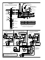
is recommended (see Fig.1).
7. Use an ohmmeter to make insulation and continuity checks on the cable after the pump is installed. This locates any fault in
the cable.
CONNECTING PRESSURE SWITCH & POWER CABLES:
Employ a licensed electrician to do the wiring.
All wiring must be done in accordance with applicable national and local electrical codes.
Refer to either Fig. 2, 3, 4 or 5 for typical installation wiring diagrams.
Power supply is wired directly from the main switch to a separate fused disconnect switch. Consult electrician or dealer for correct
circuit breaker or fuse amp rating.
•
•
All single phase motors are automatically protected against overload damage by built-in thermal control element.
Three phase motors require a magnetic starter equipped with three-leg protection having quick-trip, ambient
compensated overloads (heater) of correct size for the horsepower of the motor. Consult dealer or electrician.
Use an ohmmeter to make continuity and insulation checks after the installation is complete.
NOTE:
For three (3) wire single phase pumps, connect the three (3) colored wires of the pump cable to the
matching black, red and yellow terminals of the motor control box, i.e. always connect like colors.
For two (2) wire single phase pumps, connect pump cables directly to load terminals of the pressure
switch (color matching is not necessary).
NOTE: Refer to Pre-installation Preparation section of this manual for information regarding lightning arrestors.
PAGE 3
INITIAL START-UP:
CHECK THE PUMP AND WELL PERFORMANCE BEFORE MAKING FINAL CONNECTION TO TANK.
1. With all electrical connections complete and pump now lowered to desired depth, install a gate valve in the
discharge pipe near well for preliminary test run. Partially open the valve.
2. Turn on power to start the pump.
3. Open valve gradually to give full flow.
4. If the water is not clear, let the pump run until water clears. If water does not clear in 30 minutes, stop pump and
take necessary steps to correct the condition. After the water has appeared clear, check for sand by discharging
into a clean bucket.
5. Close valve until maximum required systems flow rate is obtained. Ensure that the pump does not lower the
water in well to a point where the pump loses prime.
6. Remove gate valve for permanent installation to tank.
CONNECTING TO PRE-CHARGED TANK:
See Fig. 1 for installation diagram.
1. Check air pre-charge in tank before starting pump. Adjust pre-charge to 2 PSI below pump cut-in setting.
2. The pressure tank should be as close as possible to the pressure switch. Connect all piping as shown in diagram.
3. Start pump. Pressure in tank will build up to cut-off pressure of pressure switch setting. The system should now
operate automatically.
CONTROLLING WEAK WELLS:
A weak (low-yielding) well exists when the output rate from the pump is greater than the recovery rate (yield) of the well.
It can lower the water level in the well to the pump suction screen, causing a mixture of air and water to enter the pump.
Pumping may stop because the pump cannot generate pressure with insufficient water. If this occurs, the column of water
already in the drop pipe holds the pumps check valve closed and an airlock may develop inside the pump. An airlock
inside the pump creates inadequate lubrication and cooling for the pump stages and motor. Damage can result if the
power is not cut off quickly. Use one or more of the following methods to correct and/or protect this installation:
1. If possible, install additional length of drop pipe to place pump lower in the well.
2. Install a PUMPSAVER electronic motor load sensing device.
3. Remove the pump “built-in” or external mounted check valve, and install a spring-loaded check valve 5 to 10 ft.
maximum above the pump discharge. Moving the check valve this distance above the pump provides a column of
drop pipe for air to escape to as the pump attempts to prime after well recovery.
4. Install a Dole flow control in the discharge pipe before (upstream from) the pressure switch and tank. This restricts
the output rate from the pump, delivering a constant capacity regardless of pump discharge pressure and rate of
water drawn from the pressure tank. The usual way to determine what size of flow control to use is to throttle the
discharge gate valve to a capacity that the well will yield without drawing down. After pump has operated at this
capacity for a sufficient time to be sure it is suitable, measure the flow in gallons-per-minute and select a flow
control size nearest to this capacity. A tank with larger draw-down capacity (gallons) should be considered for
more water storage.
5. Install a pump with a lower flow rating to avoid over pumping the well. Have the dealer size pump to the well yield.
6. A low-pressure cut-off switch may be considered, but only for shallow wells. Low-pressure cut-off switches detect
loss of pressure at the surface (at the pressure tank), but an air lock could have already formed inside the pump
deep down the well.
INSTALLATION IN LAKE, POND, STREAM OR FOUNTAIN:
A submersible pump is usually isolated at the bottom of a well, where electrical leakage from its motor and cable present
no hazard to life. This natural protection is lost when you install it in a lake, pond, stream or fountain since there is no way
to prevent people and livestock from entering or touching the surrounding water. We strongly recommend that such an
installation be done by a licensed electrician in conformance with all national and local electrical codes.
Grounding as instructed previously in this manual is a minimum requirement, and a ground fault circuit interrupter should
be considered. If there are no explicit national or local regulations, ask the local electric utility company for guidance.
The pump is designed to be mounted in the vertical, motor “shaft-up” position. If the pump must be mounted “shafthorizontal”, support the pump from the shore or bottom, with the shaft up 15° from the horizontal, for proper motor bearing
lubrication, and also reduce the number of starts to less than 10 per 24 hr. period to maintain normal motor thrust bearing
life expectancy. Use an external spring-loaded check valve on the pump discharge connection (internal non-spring-loaded
pump check valves are only useful for vertical installations) Shield the pump from direct physical contact. Protect pump
intake from blockage by leaves and weeds, but remember that the pump needs adequate flow over the motor for proper
cooling. A flow inducer sleeve should be used in any open body of water. Consult factory. Furthermore, always protect the
entire underwater installation from water currents, ice, boats, anchors, debris, etc..
PAGE 4
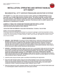
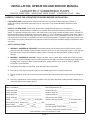
FIGURE 1INSTALLATION DIAGRAM
CONTROL BOX
THREE WIRE, SINGLE PHASE ONLY
CIRCUIT BREAKER OR
FUSED DISCONNECT
SWITCH
DIAPHRAGM TYPE,
PRE-CHARGED PRESSURE
TANK (HYDRO-PNEUMATIC)
VENTILATED
WELL SEAL CAP
AIR VALVE
PRESSURE SWITCH
SUBMERSIBLE
CABLE
PITLESS
ADAPTOR
CHECK
VALVE
DISCHARGE PIPE
CHECK
VALVE
RECOMMENDED
EVERY100'
PRESSURE GAUGE
RELIEF VALVE
TO HOUSE SERVICE
GATE VALVE
UNION
GATE VALVE
DROP
PIPE
DRAIN VALVE
TAPE
OR CLAMP
CABLE
TO PIPE
EVERY10'
TANK TEE
TORQUE ARRESTOR
WELL CASING
BUILT-IN OR EXTERNAL
CHECK VALVE
Cut-In PSI
Cut-Out PSI
Pre-Charge (Air) Pressure
20
40
18 PSI
30
50
28 PSI
40
60
38 PSI
PUMP
SUCTION SCREEN
MOTOR
Note:Keeppumpatleast5'frombottomof
well screen or casing perforations.
WELL SCREEN OR
CASING PERFORATIONS
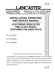
FIGURE 2 - WIRING DIAGRAM
SINGLE PHASE - TWO WIRE
1/2, 3/4, 1 or 1-1/2 HP
FIGURE 3 - WIRING DIAGRAM
SINGLE PHASE - THREE WIRE
1/2, 3/4, 1 or 1-1/2 HP STANDARD CONTROL BOX
POWER SUPPLY
240V
GROUND
(Line)
L1
T1
(Load)
(Line)
L1
T1
(Load)
(Line)
L2
T2
(Load)
(Line)
L2
T2
(Load)
PRESSURE
SWITCH
Red
Black
FUSED
DISCONNECT
SWITCH
PRESSURE
SWITCH
Ground (Green)
WELL
CASING
CONTROL
BOX
SW L1 L2 Y B R
PRESSURE
SWITCH
FUSED
DISCONNECT
SWITCH
Red
Yellow
Black
Ground (Green)
L1
T1
L2
T2
Yellow
Black
Red
Ground (Green)
FOLLOW COLOR CODING
WHEN CONNECTING
CONTROL BOX
(YELLOW TO Y, RED TO R,
BLACK TO B).
WELL
CASING
FIGURE5-WIRINGDIAGRAM
THREE PHASE
1-1/2 through 7-1/2 HP
POWER SUPPLY
240V
GROUND
L1 L2 R Y B
X
FUSED
DISCONNECT
SWITCH
LINE CONTACTOR INCLUDED IN CONTROL BOX TO PROTECT PRESSURE SWITCH
CONTROL
BOX
NEUTRAL
NEUTRAL
X
120V 120V
FOR1/2HP,115VMOTORINSTALLATIONSONLY:
IN THE FUSED DISCONNECT SWITCH,
CONNECT L2 TO NEUTRAL LINE FROM POWER
SUPPLY AS SHOWN, INSTEAD OF L2 TO "X".
{
120V 120V
POWER SUPPLY
240V
GROUND
FOR1/2HP,115VMOTOR
INSTALLATIONS ONLY: IN THE
FUSED DISCONNECT SWITCH,
CONNECT L2 TO NEUTRAL LINE
FROM POWER SUPPLY AS SHOWN,
INSTEAD OF L2 TO "X".
FIGURE 4 - WIRING DIAGRAM
SINGLE PHASE - THREE WIRE
2,3or5HPDELUXECONTROLBOX
FOLLOW COLOR CODING
WHEN CONNECTING
CONTROL BOX
(YELLOW TO Y, RED TO R,
BLACK TO B).
WELL
CASING
POWER SUPPLY
L1 L2 L3
GROUND
L1
L1
T1
L2
T2
L2
L3
T2
T3
COIL
PRESSURE
SWITCH
FUSED
DISCONNECT
SWITCH
T1
THIS IS THE MOST COMMON TYPE OF CONTROL ENCOUNTERED.
SINCE THE COIL IS CONNECTED DIRECTLY ACROSS THE POWER LINES,
L1 AND L2, THE COIL MUST MATCH THE LINE VOLTAGE.
FOR LOW VOLTAGE TRANSFORMER CONTROL OR EXTERNAL VOLTAGE CONTROL,
CALL DEALER OR ELECTRICIAN.
WELL
CASING
PAGE 5
MAGNETIC STARTER
(EQUIPPED WITH QUICK-TRIP,
AMBIENT-COMPENSATED
OVERLOADS (HEATERS)
OF CORRECT SIZE FOR THE
HORSEPOWER OF THE
MOTOR).
PROBLEM
TROUBLE SHOOTING
POSSIBLE CAUSE/SOLUTION
PUMP DOES
NOT START:
1. No power. Check voltage at line terminals. The voltage must be ± 10% of rated voltage.
Contact power company if voltage is low.
2. Fuses blown or circuit breakers tripped. Check fuses for recommended size and check for
loose, dirty or corroded connections in fuse receptacle. Check for tripped breakers.
Replace with proper fuses or reset circuit breaker.
3. Defective pressure switch. Check voltage at contact points. Improper contact at switch points
can cause voltage less than line voltage. Replace pressure switch or clean points.
4. Control box malfunction (3-Wire, single phase only). Call dealer or electrician for repair or
replacement.
5. Defective wiring. Check for loose or corroded connection or incorrect wiring. See wiring
diagram.
6. Defective cable or motor. Splices bad. Call dealer or electrician.
7. Electronic motor load sensing device (drawdown protection) has pump turned off (if installed).
8. Reset low pressure cutoff switch (if installed).
PUMP STARTS
BUT OVERLOAD
PROTECTOR TRIPS
OR FUSES BLOW:
1. Wrong size fuse or circuit breaker. Call dealer or electrician for recommended size.
2. Wire size too small. Call dealer or electrician.
3. Control box malfunction (3–wire, single phase only). Call dealer or electrician for repair or
replacement.
4. Incorrect voltage. Check voltage at line terminals. Voltage must be ± 10% of rated voltage.
5. Defective wiring. Check for loose or corroded connections or incorrect wiring. See wiring
diagram.
6. Defective cable or motor. Splices bad. Call dealer or electrician.
7. High ambient (atmospheric) temperature. Check temperature of control box. The box must
not be hot to touch. Direct sunlight or other heat source can raise temperature of box causing
protectors to trip. Shade box, provide ventilation or move box away from heat source.
8. Pump or motor stuck or binding. Pump may be sand bound. Amp readings will be 3 to 6 times
higher until the overload trips. If necessary, remove pump from well (make all possible above
ground checks first). If pump is locked, replace it. Clean well of all sand before reinstalling
pump.
PUMP STARTS
TOO FREQUENTLY:
PUMP RUNS
CONTINUOUSLY:
PUMP DELIVERS
LITTLE OR NO
WATER:
01/14
1. Pre-charged tank water-logged (loss of air pressure). Adjust air pressure to 2 PSI less than cutin pressure (when there is no water pressure on system). Check tank for leaks. Must be air and
water tight. Replace if necessary. Is tank sized too small to meet system
requirements?
2. Defective pressure switch or switch out of adjustment. Re-adjust or replace pressure switch.
Pressure switch should be located as close to the tank as possible.
3. Check valves leaking. Damaged or defective check valve will stick open and leak back.
Replace if defective.
4. Leak in system. Tank losing pressure through leaking plumbing fixtures. Check all aboveground piping for leaks. If none, pull pump and check all pipe connections and connection of
pipe to pump.
1. Pressure switch may have welded contacts. Switch may be out of adjustment. Clean contacts,
replace switch or adjust setting.
2. Low water level in well. Pump may exceed well capacity. Pump may be air-locked. Refer to
“controlling weak wells” information in the installation section of this manual.
3. Leak in system. Check system for leaks. Replace damaged pipe or repair leaks.
4. Worn pump. Symptoms of a worn pump are similar to those of drop pipe leak or low water level
in well. Reduce pressure switch setting, if pump shuts off worn pump may be the fault.
1. Pump not submerged in water. Low water level in well. Pump may be air-locked. Refer to
“controlling weak wells” information in the installation section of this manual.
2. Check valve installed backwards. Reverse and re-install.
3. Check valve stuck closed. Replace if defective.
4. Pump intake screen blocked. Pump in mud. Pump impellers partially clogged or plugged. Pull
pump and clean. Raise pump if necessary, i.e. reset pump depth.
5. Setting too deep for rating of pump. Call dealer, check pump rating table.
6. Piping might be split and leaking.
7. Low voltage. Wire size to small. Call dealer or electrician.
8. Incorrect rotation (3 phase only). Call dealer or electrician. Refer to “rotation” information in the
installation section of this manual.
9. Worn pump.
LANCASTER PUMP A DIVISION OF C-B TOOL
1340 Manheim Pike • Lancaster PA 17601-3196 • Tel: 717-397-3521
• Fax: 717-392-0266 • www.lancasterpump.com
PAGE 6