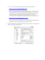
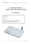
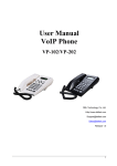
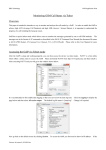
1
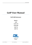
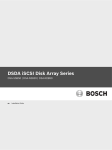
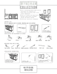
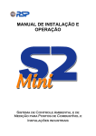
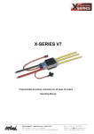
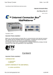
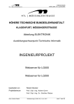
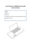
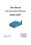
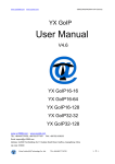
DBL's Service Manual
Warnings: This manual is intended to guide a technicians or customers who would like to repair DBL's
devices (GoIP, SIM Bank, FXS/FXO gateways) at his/her own risk. DBL SHALL NOT be held responsible
for any damages as a result of the repair action described below.
1. Restoring FLASH with Corrupted Image
Symptoms for corrupted FLASH image:
o All LEDs lights up without blinking and the device does not reboot itself.
When the above symptoms occurs, please contact technical support ([email protected])
to verify if the FLASH image is corrupted.
To restore corrupted FLASH image, you need setup your device for COM port access. You
need to build or purchase a special COM cable so that your PC can communicate with the
device via the COM port. Since both COM ports (your device and PC) operates at different
voltage levels, this special COM cable handles the voltage conversions. The circuit
schematics of this cable is shown below.
If you do not want to build your COM cable, you can purchase the COM cable kit from
DBL. This cable kit consists of the following items.
a) A special COM cable
Note: The side labeled in black is pin 4 (GND).
When you have the cables required ready, please follow the following procedures carefully
to setup your device.
a) Disconnect the power to the device.
b) Use a proper size Phillips screwdriver to take out all screws that are located at the
bottom of the device chassis / case.
c) Open the top case carefully and then locate a 4-pin SIP pads (see the sample picture
below) that are located either on the bottom or the top PCB depending on your
device. However, there is only one 4-pin SIP pads as labeled as J1 in the picture
below. By convention, the square pad is pin 1 (TxD) and the last pad in the row is pin
4 (GND).
d) Plug the COM cable into the 4-pin SIP pads as shown in the picture below. Please
make sure that the connector with the side painted in BLACK (pin 4) is aligned with
the round pad as shown in the picture below.
e) Apply pressure to the connector by tilting it to one side and hold it with a piece of
tape as shown in the picture above.
f) The other side of the COM cable is a DB9 female connector. You can connect it
directly to a PC that has a COM port. Use the extension cable if needed. If you don't
have a COM port in your computer, you can use the USB-to-Serial Adapter that is
included in the cable kit.
g) If you are using the US-to-Serial Adapter, you need to install the driver first. Please
download the driver from the URL below.
http://118.142.51.162/update/USBCOM-driver.rar
After you have installed the driver, please view the setting for Ports (COM & LPT) in the
Device Manage under Control Panel to make sure that the USB Serial Port is installed
properly. Please note the COM port number since you will need to use it when you try
to setup a COM port communication software.
h) Here is a typical setup using the special COM cable and the USB-to-Serial adapter for
restoring the FLASH image.
i)
Please still keep the power to the device unplug and start prepare your computer
environment. You will first need to download the following software utilities and save
them to the desktop or the same directory. There is no need to install these utilities.
1. MINI SERVER - This utility sets up your computer environment so that the flash
image can be downloaded from when restoring the FLASH image.
http://118.142.51.162/update/MiniWebServer.exe
2. PUTTY - This utility enable COM port communications with the device.
http://118.142.51.162/update/PUTTY.exe
3. Remote Desktop Software and Remote Desktop Connection - This utility enable
PC-to-PC remote connection, so that DBL's technical support can access your
computer remote. Your computer firewall or protection software may warn or
block the download of .exe file. Please enable to download. For more
information, please visit AMMYY's home page www.ammyy.com/en/index.html.
http://118.142.51.162/update/AA_v3.5.exe
If you have any concerns, we could try to use another Remote Desktop software.
However, this may cause additional time to setup on our side.
j)
To test the COM port communications, please execute PuTTY with the settings shown
below. Click Open to execute PuTTY.
k) You can now plug in the power to the device and boot up message from the device
should be displayed in the PuTTY window. Otherwise, please double check on the
hardware setup and the software configuration.
l)
Up to this point, both hardware and computer are ready for restoring FLASH image.
Please contact our technical support via email first ([email protected]). When we
try to restore FLASH image, we will to real time communications. Please also setup
set up Skype to communicate with us directly. (Skype ID: support-dbl)
Notice:pl help us to access autoboot command ,power it on then you must
press any key to access it . information like this:
Watchdog setup.
Hit any key to stop autoboot: 0
Watchdog setup.
## Booting image at 80030000 ...