1
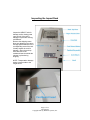
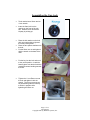
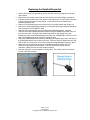
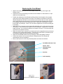
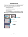
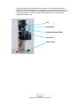
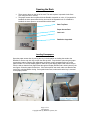
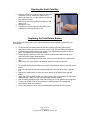
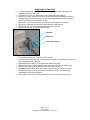
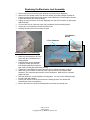
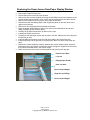
IMPACT Rack
Service Manual
Page 1 of 14
182-0026-05
Copyright 2001 by Bellatrix Systems, Inc.
Inspecting the Impact Rack
Inspect the IMPACT rack for
damage and/or missing parts
upon arrival. If the rack is
damaged or parts are missing,
call Bellatrix.
Remove the shipping carton.
Note any damage to the carton
and pay special attention to the
corresponding area of the rack.
Visually inspect the rack for
damage. Open the rack top
door and remove the
cardboard insert that holds the
elevator in place during
shipping.
NOTE: Transportation damage
claims must be made to the
freight carrier.
Page 2 of 14
182-0026-05
Copyright 2001 by Bellatrix Systems, Inc.
Assembling the Cam Lock
•
Tools needed are a 22mm and an
11mm wrench.
•
Insert the Cam lock into the
opening on the front of the coin
box. Orient the lock so that the
Keyway is pointing up.
•
Place the lock washer on the bolt
with one notch pointing right and
the other pointing down.
Place the two spacer washers onto
the bolt.
Put the 22mm nut on and tighten it
with the wrench to the base of the
vault.
•
•
•
Put the key into the lock and turn it
to the unlock position. Install the
butterfly plate onto the bolt with the
machined corners bending towards
the back.
•
Tighten the 11 mm Esna nut onto
the bolt and tighten it with the
wrench. The 22 mm wrench can
be placed along side the butterfly
to hold it in position while
tightening the Esna nut.
Page 3 of 14
182-0026-05
Copyright 2001 by Bellatrix Systems, Inc.
Replacing the Datalink/Keyswitch
•
•
•
•
•
•
•
•
•
Use the cam lock key to open the top door of the rack. Lift the rack top door to the fully
open position.
Remove the two holding screws from the lock access cover with a Phillips screwdriver.
Push the elevator down until the lock access cover folds down. This will hold the elevator
in place, and exposes the lock and cabling. Locate both ends of the Impact cable
assembly inside the rack.
Open the Coin Wizard access cover and remove it by pushing it back and lifting it out.
Remove the existing datalink/keyswitch by removing the spring clip and disconnecting the
6 pin connector from the IMPACT cable.
Slide the white nylon washer onto the replacement Datalink/keyswitch. Insert the
connector end of the Datalink/Keyswitch Cable through the Datalink/keyswitch hole from
the front of the rack. The white nylon washer should be on the outside of the rack
between the base of the Datalink/keyswitch and the rack. IMPORTANT: Orient the round
hole in the Datalink body to the right when facing the rack.
Fasten the Datalink/keyswitch in place by attaching the supplied spring clip to the body of
the Datalink/keyswitch on the inside of the rack. Place the clip flush against the rack, tab
side up and out. Press down on the tab to secure the Datalink/keyswitch tightly in place.
Attach the 6-pin connector at the end of the Datalink/keyswitch cable to the 6-pin
connector of the Impact cable assembly. The connectors are keyed for correct
orientation. Make sure the connector snaps into place.
Stow the cabling so it is not exposed to moving parts. The cabling can be run through
the slot in the rack’s ribbing.
Page 4 of 14
182-0026-05
Copyright 2001 by Bellatrix Systems, Inc.
Replacing the Coin Wizard
•
•
•
•
•
•
•
•
Open the rack top and remove the Coin Wizard Access Cover by removing the two
holding screws.
Loosen the nut on the mounting pin and lift the Coin Wizard out. Disconnect the 12 pin
cable from the reader body.
Position the replacement Coin Wizard by sliding it down into the space at the top right
corner of the rack, directly behind the coin slot. The channel on the bottom of the Coin
Wizard backplate should catch on the metal tab on the inside of the coin return opening
on the rack. Align the mounting pin on the rack with the keyhole shaped slot at the top of
the backplate and slide the Coin Wizard into place. Make sure the faceplate is snug to
the rack with very little play. Use a 7/32” nut driver to tighten the nut on the mounting pin
if necessary.
Attach the 12-pin connector on the Impact cable assembly to the 12-pin connector on the
Coin Wizard. The connectors are keyed for correct orientation. Make sure the connector
snaps into place. Do not allow the cable to run under the coin box. This could cause the
coin doors not to operate correctly.
Make sure that the 4-pin connector on the electronic lock is snapped securely to the 4-pin
connector on the Impact cable assembly. Press the blue reset button on the back of the
Coin Wizard housing and verify that the door lock opens.
Close the Coin Wizard access cover by inserting it in place and sliding it forward.
Pull the lock access cover up and re-insert the holding screws. The elevator will
automatically rise to its top position.
Be sure the cam lock is in the fully unlocked position and close the rack door.
Coin Wizard Access Cover
Impact cable
assembly 12-pin
Connector
Coin Slot
Lock Assembly
Page 5 of 14
182-0026-05
Copyright 2001 by Bellatrix Systems, Inc.
Anchoring the Impact Rack
When the Impact rack is placed on the street, it should be anchored in place. This can be done by
chaining it to a secure object, bolting the rack to the ground or weighting it down with ballast.
You will need the special #25 Torx© driver that was included with your shipment and any other
hardware or tools necessary to bolt or chain the rack or install concrete ballast.
Remove the 4 Torx© screws at the bottom of the left and right sides of the rack.
• Lift and remove the rack from its base.
• Tip the base up.
• Insert concrete ballast between the L-brackets on the underside of the base, or
• Use the base anchor bolt holes to anchor the base to the ground. Make sure the base is
oriented with the drain hole towards the back.
• Replace the rack on its base.
• Replace the 4 Torx© screws at the bottom of the left and right sides of the rack.
• Or, place a chain or cable through the chain holes in the back of the rack. Fasten the
rack to a secure object.
IMPORTANT: Be sure that the cables/chains do not interfere with the movement of the paper
door counterweight.
Torx Screws
Drain Hole
Anchor-Bolt Holes
Chain Holes
Page 6 of 14
182-0026-05
Copyright 2001 by Bellatrix Systems, Inc.
The Coin Wizard
•
•
•
•
•
•
•
•
•
•
•
•
The Coin Wizard accepts and reads coins, drops them into the vault or returns them to
the customer and releases the paper access door.
The paper door is opened and the prices are set into the Coin Wizard using a
changeover key or a Wand, depending on the model. When docked with a wand, it will
take 2 seconds to open the door. The wand will set the price automatically. To set the
price with a keyswitch, turn the key to the required position. Each position on the
keyswitch represents a specific price. When the key is turned, the door lock will cycle
and open. If the key is turned one position, the lock will cycle once. If the key is turned
through two positions (i.e. from position 1 to position 3,) the lock will cycle twice. This is
important to note so the door doesn’t accidentally get left open.
Coins inserted into the Coin Wizard are recorded and held in an internal escrow. Each
time a coin is dropped into the Coin Wizard, it is detected by a photo emitter/detector pair
at the top of the coin path. This will activate two additional pairs of photo
emitter/detectors positioned at the bottom of the coin path. As the coin drops, it is
pressed against the back of the coin path by the roller on the inside of the coin path. This
also helps slow the coins so that they drop at a consistent rate. If the coin has ferrous
content (iron) and the slug detect feature is turned on, the magnet in the center of the
coin path flap will cause it to be rejected. Otherwise, as the coin passes the second pair
of photo emitters/detectors, the diameter is noted and compared to a table in the Coin
Wizard memory. The value of the coin is stored and compared to the current price until
enough coins have been inserted for a sale. Each time a valid coin is read the red LED
on the reader assembly will flash.
If the coin return button is pushed before enough coins for a sale have been recorded,
the coins are dropped into the coin return box on the front of the rack. The coin return
will operate once to return the coin(s.) After this, it will not operate again until another
coin is dropped through. This prevents a user from pushing the coin return button
continuously, running down the battery.
Once enough coins for a sale are recorded, the Coin Wizard activates the motor that
releases the paper access door and the coin return button becomes inoperable. The
motor runs for 1.0 second, turning the cam to pull the spring that releases the paper
access door lock.
After releasing the paper access door, the Coin Wizard waits for 10 seconds for the door
to be lifted open. (A micro switch in the lock senses when the door is opened.) If the
door is not opened within the 10 seconds, it is re-locked and the money is returned to the
customer. If the door is opened, the money is deposited into the vault. The door catch is
then reset so that it will lock when the door is closed.
There are some timing issues that are important to understand when testing the Coin
Wizard.
It takes the Coin Wizard 1.0 second to run the motor to release the paper access door
after it records the last coin for a sale
Once the paper access door is opened, it takes the Coin Wizard 0.5 second to run the
motor to latch it again.
Once the paper access door is opened, it takes the Coin Wizard 4 seconds to be able to
read new coins.
When a Wand is docked to the Coin Wizard, it takes 2 seconds to release the paper
access door.
There may be instances when it is necessary to reset the Coin Wizard. The Coin Wizard
will need to be reset before reprogramming new prices and before entering new ID
numbers. Resetting the Coin Wizard resets the microprocessor on the circuit board but
does not affect coin tables, pricing, edition structure, sales or other data stored in
memory. To reset the Coin Wizard, press the blue Reset button on the back of the reader
Page 7 of 14
182-0026-05
Copyright 2001 by Bellatrix Systems, Inc.
housing. Resetting will initiate a sequence of events. The red LED will flash and the
escrow arm will cycle approximately 125 degrees to the right, opening the retain door. It
will then cycle about 25 degrees to the left, slightly opening the return door, then returns
to the center position. The electronic lock will cycle and open if the Coin Wizard is
installed in the Impact rack.
LED
Reset Button
Slug-Detect Magnet Holder
Escrow Arm
Datalink Cable
Page 8 of 14
182-0026-05
Copyright 2001 by Bellatrix Systems, Inc.
Opening the Rack
•
•
There are two doors on the top of the rack. The rack top door is opened via the Cam
Lock using the Cam Lock key.
The paper access door is opened with the Datalink, keyswitch or coins. If a keyswitch is
installed, the door opens when the key is turned in the keyswitch lock. If a Datalink is
installed, the door opens on communication with a wand.
Rack Top Door
Paper Access Door
Cam Lock
Datalink or keyswitch
Loading Newspapers
Open the paper access door by turning the key in the keyswitch or docking the wand to the
Datalink or use the cam lock key to open the rack top door. Prop the door open using the paper
access door support. Remove old newspapers and place current newspapers face up on the
paper elevator. To load the display paper it under the Lexan display paper holder from the top or
from the side so that the front page shows through the Display Window and is held in place by the
two fingers. Close the paper access door. If the rack top door was used, make sure that the cam
lock is fully unlocked before closing. If a keyswitch was used, make sure that the key is returned
to the proper position.
Page 9 of 14
182-0026-05
Copyright 2001 by Bellatrix Systems, Inc.
Opening the Vault Coin Box
•
•
•
•
Insert the Camlock key into the vault lock and turn it
clockwise to unlock. Make sure that the key is
pushed all of the way in or the lock will only turn half
way and will not open.
Remove the coin box by pulling it towards you and
sliding it out.
Remove the coins.
Push the coin box back into the rack and turn the
Camlock key counterclockwise to lock.
Replacing the Coin-Return Button
A #2 Phillips screwdriver and a 14mm Open-End Wrench will be needed to replace the coin
return button.
•
•
•
•
•
•
•
•
•
•
•
•
•
To remove the Coin Return Button lift the rack top door to the fully open position.
Remove the holding screws from the lock access cover using the Phillips screwdriver.
Push the elevator down until the lock access cover folds down to hold the elevator in
place. This exposes the lock and the cabling.
Detach the 2-pin connector at the end of the coin return button cable from the 2-pin
connector on the Impact cable assembly.
Remove the nut and washer from the back of the coin return button on the inside of the
rack.
Remove the coin return button and attached cable from the front of the rack.
To re-install the Coin Return Button remove the nut and washer from the new coin return
button.
Insert the coin return button into the associated hole in the front of the rack, connector
first.
Replace the washer and nut on the coin return button on the inside of the rack and
tighten.
Attach the 2-pin connector on the coin return button to the 2-pin connector on the Impact
cable assembly. Make sure the connector snaps securely in place.
Run the cabling through the slot in the rack’s ribbing so it is not exposed to moving parts.
Pull the lock access cover up and re-insert the holding screws. The elevator will
automatically rise to its top position.
Be sure the cam lock is in the fully unlocked position and close the rack top door.
Page 10 of 14
182-0026-05
Copyright 2001 by Bellatrix Systems, Inc.
•
•
•
•
•
•
•
•
Replacing the Cam Lock
A 7/8” box end wrench, a 11mm box end wrench and a #2 Phillips screwdriver are
needed to replace the cam lock.
To Remove the Cam Lock lift the rack top door to the fully open position.
Remove the holding screws from the lock access cover using the Phillips screwdriver.
Push the elevator down until the lock access cover folds down to hold the elevator in
place. This exposes the lock and the cabling.
Remove the 11mm nut and washer from the bolt on the inside of the cam lock.
Remove the Z bracket from the bolt on the inside end of the cam lock.
Remove the 7/8” lock nut that attaches the cam lock to the rack.
Remove the cam lock from the front of the rack.
Z bracket
Cam Lock
Lock Access Cover
•
•
•
•
•
•
•
•
To re-install the Cam Lock, remove the 7/8” lock nut.
Insert the cam lock into the hole in the front of the rack. Be sure the key slot on the cam
lock is positioned to the right side.
Replace and tighten the 7/8” lock nut from the inside of the rack.
Remove the 11mm nut and washer from the bolt on the inside end of the cam lock.
Place the Z bracket on the bolt on the inside end of the cam lock.
Replace and tighten the washer and 11mm nut on the inside end of the cam lock.
Pull the lock access cover up and re-insert the holding screws. The elevator will
automatically rise to the top position.
Be sure the cam lock is in the fully unlocked position and close the rack top door.
Page 11 of 14
182-0026-05
Copyright 2001 by Bellatrix Systems, Inc.
Replacing the Electronic Lock Assembly
•
•
•
•
•
•
•
Lift the rack top door to the fully open position to remove the lock assembly.
Remove the two holding screws from the lock access cover with a Phillips screwdriver.
Push the elevator down until the lock access cover folds down. This will hold the elevator
in place and expose the lock and cabling.
Unplug the 4-pin connector on the lock assembly from the 4-pin connector on the Impact
cable assembly.
Turn the cam lock all of the way to the right (clockwise) into the locked position.
Loosen the ¼-turn fasteners on each end of the lock.
Carefully lift and remove the lock from the rack.
Lock Release
Spring
¼-Turn Fasteners
Installing the Lock Assembly
•
•
•
•
•
•
•
Make sure the Camlock is all of the
way to the right (clockwise) in the
locked position.
Carefully place the lock assembly
in position, making sure that the
lock release spring fits through the
hole in the mounting bracket without jamming.
Tighten the ¼-turn fasteners on each end of the lock, making sure that it is secure.
Attach the 4-pin connector on the lock to the 4-pin connector on the Impact cable
assembly. The connectors are keyed for correct orientation. Make sure the connector
snaps into place.
Stow the cabling so it is not exposed to moving parts. You can run the cabling through
the slot in the rack’s ribbing.
Pull the lock access cover up and re-insert the holding screws. The elevator will
automatically rise to its top position.
Be sure the cam lock is in the unlocked position and close the rack top door.
Page 12 of 14
182-0026-05
Copyright 2001 by Bellatrix Systems, Inc.
•
•
•
•
•
•
•
•
•
•
•
•
•
•
•
Replacing the Paper Access Door/Paper Display Window
Note: The paper display window is replaced by replacing the paper access door.
Removing the Paper Access Door
Lift the rack top door to the fully open position.
Remove the door counter-weight by removing the two Phillips screws and washers on the
counter-weight support bracket. Next, remove the hex screws with a 6mm Allen wrench.
Remove the E-rings from the hinge pins of the paper access door.
Release and lower the display paper holder by pressing down on the latch lever at the
upper back of the tray.
Remove the door hinge pins with a flat blade screwdriver.
Raise the display paper holder by placing your hand on the underside of the tray and
gently pushing it up until it locks in place.
Carefully lift the paper access door up and out of the rack.
Installing the Paper Access Door
Carefully set the new paper access door in place in the rack. Make sure the lock pin goes
into the lock pin hole.
Insert the paper access door hinge pins with their heads to the inside of the rack.
Install the E-Rings into the grooves on the hinge pins. Make sure the E-Rings snap into
place.
Replace the counter-weight by holding it between the counter weight support arms and
inserting the 6mm hex screws. Insert the hex screws through the support arms and screw
them into the threaded holes in the counter weight.
Make sure the cam lock is in the unlocked position and close the rack top door.
Paper Access Door
Lock Pin
Display-Paper Holder
Rack Top Door
Hinge Pin and E-Ring
Door Counter-Weight
Hinge Pin and E-Ring
Door Counter-Weight
Page 13 of 14
182-0026-05
Copyright 2001 by Bellatrix Systems, Inc.
•
•
•
•
•
•
•
•
•
•
•
•
•
•
Operational Checklist
Vault lock opens and closes smoothly
Datalink/keyswitch cable is securely clipped in place
Bottom of Coin Wizard is secured behind metal tab on rack
Top of Coin Wizard is secured by metal pin on Rack
Pressing the blue reset button on the Coin Wizard causes the rack door lock to open
indicated by the movement in the electronic lock assembly internal mechanism
2-pin, 4-pin and 6-pin cables are run through the slot in the Rack’s ribbing (so they are
kept away from moving parts)
2-pin Connector snapped in place to coin return button cable
4-pin Connector snapped in place to electronic lock cable
6-pin Connector snapped in place to Datalink Cable
12-pin Connector snapped in place to Coin Wizard
Access cover in place and closed
Lock access cover is closed and secured with holding screws
Rack top door is closed and locked (using Cam Lock key)
Paper access door is closed and locked
Page 14 of 14
182-0026-05
Copyright 2001 by Bellatrix Systems, Inc.