1
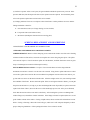
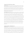
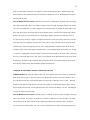
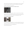
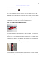
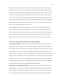
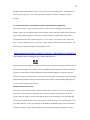
1
HEHR INTERNATIONAL
www.hehrintl.com
SERVICE MANUAL
Index
General
Analyzing and Repairing Leaks: What's a leak?
Analyzing: hard operation
Glass: Some Special Notes
Glass Care
Glass replacement: Sliding Panes
Torques, Crank-Outs & Awnings
Hardware Replacement
Screens: Replacement and Re-screening
How to Quiet Squeaks
Fix a Door
Slider Latches
Emergency Exit Latches
Operators for Torques, Crank-Outs & Awnings
2
GENERAL
Hehr International’s products have long been designed to be serviceable in the field. This means that
complete replacement of a window, door, or other product is often not necessary. Often, the product can
even be repaired without removing it from the wall of the vehicle.
This on-line Field Service Manual has been designed to make field repair as quick and economical as
possible.
Some repairs are inherently uneconomic, however. These include situations involving complete removal of
the installed product, major disassembly of it, multiple glasses and frame component replacement, and any
other instance where the combined labor and parts costs exceed the acquisition cost of a new unit.
Warranties: Hehr International’s Limited Warranty is printed on the back of every Hehr invoice. Any
Warranty claims must be processed through the Original Equipment Manufacturer’s Service and Warranty
System. Because of the wide variety of potential repairs for Hehr products, there is no Standard Hours
Repair Schedule. All Warranty Claims are reviewed for reasonability, completeness and clarity. Excessive
labor times, rates, part costs, and freight will be reviewed and may be denied, wholly or in part.
Window identification: If it is necessary to order replacement windows or parts, proper identification of
the existing window is very important. All Hehr windows are labeled prior to shipment; however, the label
is only accessible by removal of the window from the wall.
As a reasonable alternative, provide the following information to the factory service center to ease in
identification:
1. The manufacturer’s part number, if known.
2. The manufacturer’s name, vehicle model and year
3. A sketch or photo of the window
4. Outside dimensions of the window flange
5. Window frame color
6. Window glass color
7. If the window is angled, the angles in degrees off the vertical.
8. If the clamp ring (inside trim) is damaged, the exact wall thickness, including the compressed flange
seals being used.
3
ANALYZING AND REPAIRING LEAKS
What’s a leak?
In general, a leak is:
(A) Water infiltration between the stationary glass and the window frame.
(B) Water running down the inside of a ventilating pane
(C) Any condition where water accumulates in the windowsill, overflows, and runs down the inside
wall.
The following are not automatically leaks:
(A) Presence of water in the windowsill. Ventilating windows will often admit some water; this is
particularly true when subject to direct high pressure flows. They are designed to manage the water that
comes in during average storm events and normal vehicle washes. They cannot withstand submersion, nor
extraordinary flow velocities and volumes. All ventilating sliding windows and many awning-type
windows are provided with "weep slots" or "drain slots." These allow any water coming in, whether
through bypassing the opening pane, or from condensation, to drain out, rather than be trapped inside the
vehicle.
(B) Water running down the inside wall. If water appears between the window frame and the clamp ring,
there is an installation leak, or the water is coming through the wall. Installation leaks occur when the
window flange has not been properly bedded; when the frame bedding has become brittle or has been
breached, such as by racking of the unit wall; improper hole cutouts, causing insufficient coverage by the
mounting flange; and walls curved, preventing a continuous seal under the window flange; Water leaks
through the wall may originate in several areas, often remote from the window. Examples are: improperly
sealed clearance lights and seams in sidewall skins.
(C) Loose glazing vinyl; in most cases, the glazing vinyl is cosmetic only and does not seal. Look for gaps
in the bedding under the glass. If present, they should be lightly caulked, allowed to set up, and the vinyl
replaced.
4
What can I do?
Window replacement is not always the best option when leaks appear. In many cases, removal and
replacement will cause new aesthetic problems, which the vehicle owner may not be satisfied with. Things
to check for:
(A) Is the window properly closed?
Sliding window latches usually include an interlock so that the sliding pane and the mullion fit together
tightly. If either is bowed away from the other, the parts may by-pass, precluding a tight seal. Pushing
outward when sliding the window closed can check this. If the vent stops earlier than it had previously, the
seal has probably been restored. Often, the bowed part can be gently bent back into the proper position.
Torque or awning windows may not seal for a variety of reasons: If the operator knob is stripped or
cracked, the panes will not close fully. The vent seals are subject to deterioration over time. Replacing
them, if indicated, will improve vent closure. Most vents have an adjustment feature. If the vent has
“triangular” pivot brackets, be sure that the bottom adjustment hole is used. This will tighten the vent
closure.
(B) Can the water evacuate?
Most sliding windows have a sloped sill (which will channel any water present outbound) and weep or
drain holes (to permit the water to flow out.) These holes are usually baffled or otherwise disguised on the
inside to minimize wind noise or “blow-back” in strong winds. Often, dirt or manufacturing debris will
accumulate over time, blocking the drain, so that water cannot escape. To fix this condition: from outside
the window, unsnap the weep hole covers, if present, but keep them handy for reuse. Use a stiff wire to
probe into the weep hole, and scrape out anything blocking the sill. When you are sure that the area is clear,
reinstall any weep slot covers.
(C) Where is the water entering?
A process of elimination can be used to isolate the leak. Using duct tape, cover all suspected points of entry
for water. If the leak persists, the water is entering elsewhere. If the leak stops, isolate the leak by
removing one piece of tape at a time until the leak reappears. Depending on the leak source, various
strategies can be employed, such as caulking, re-bedding, vinyl replacement etc.
5
(D) Is the window installed correctly?
Radius windows are usually installed with an inside clamp ring. This part is screwed together with the
window frame, clamping the wall between them. The clamp rings vary, depending on the wall thickness
specified by the manufacturer of the vehicle. This wall thickness must accommodate the actual wall
materials, plus whatever sealant is used under the outside window flange. If the clamp ring used is too
thick, the window will not clamp tightly to the wall. When this happens, the flange seal can be easily
breached and a leak occurs. If the window flange is not snug to the sealant around the outside, and the
clamp ring not snug to the inner wall, you should order a replacement clamp ring. In general, a clamp ring
is better if slightly too thin for the wall, rather than too thick.
(E)Air leaks and wind noise:
Unless the window also leaks water, wind noise should not be assumed to be a true leak. Excessive interior
noise may be a function of vehicular design. A contributing factor can be the shape and placement of
outside accessories such as mirrors. Replacement of the window will not affect wind noise when this case
applies.
ANALYZING HARD OPERATION
ANALYZING HARD OPERATION IN SLIDERS
-- Sliders can be hard to open or close for a variety of reasons. All of the following should be investigated
before ordering a replacement window:
---Clamp ring roll: Radius windows are usually installed using an inside clamp ring. This part is screwed
together with the window frame, clamping the wall between them. The clamp rings vary, depending on the
wall thickness specified by the manufacturer of the vehicle. This wall thickness must accommodate the
actual wall materials, plus whatever sealant is used under the outside window flange. If the clamp ring used
is too thin, there will be a gap between the clamp ring and the inner part of the window. The application of
the mounting screws will cause distortion of the window frame, resulting in a hard sliding window. This
situation can usually be remedied by installing the proper clamp ring.
---Wrong mounting screws: The correct window installation screw for most Hehr windows (other than
heavy transit buses) is a #6 X 1/2 in. pan head sheet metal screw, “A” point or self tapping. Use of a longer
6
or larger (thicker) screw will often affect window sliding by distorting the track, which the opening pane
rides on. In most cases, this situation is not remediable, and the window must be replaced. The warranty
will not apply since the failure and damage was caused by installation error.
---Damage to the window frame: Dents in the frame can cause the slide channel to be pinched, leading to
increased slide resistance. Visually inspect the frame surface for any signs of distortion. If distorted, use a
narrow block and mallet to gently tap the frame back into alignment. Check slider for improved operation.
---Frame interference: Check for clearance between the sliding pane and the mullion (the bar between the
glass panes.) Mullions can sometimes be twisted due to impact, or improper assembly. If the mullion/slider
space seems inadequate, try rotating the mullion to permit greater clearance.
---Damage to track: All sliding panes (except heavy transit windows) are captured in a plastic or soft
rubber track within the window frame channel. This track can become damaged or distorted and this may
cause hard (or no) sliding. Usually, it is impossible to feel down into this track. In order to check for
damage, drag a small (1/8") flat blade screwdriver along the top and bottom tracks. Any resistance will
result in increased sliding resistance, and the damaged track needs to be replaced. Please see the
instructions on glass replacement elsewhere in this manual for track replacement procedures.
---Debris: If the tracks are not properly cleaned upon completion of the vehicle, debris, such as shavings,
may accumulate which can impede proper sliding action. This can be alleviated by blowing the tracks out
with compressed air, vacuuming out, or with instruments such as tweezers or long nose pliers.
---Oversize window/undersize hole: Proper installation requires that the rough opening size exceed the
window size by 3/8ths" in both height and width. If the hole is too small, the window may have been forced
into place, distorting the frame, and causing the sliding pane to be squeezed, thus increasing resistance. If
this is found to be the case, the window must be removed from the wall, and the rough opening relieved
(expanded) to allow an interference-free fit.
---Glass too thick/Track too thin: In rare cases, this can occur, due to improper parts selection at the time
of manufacturing. The possible remedies here are: Replace the track with one to accommodate thicker
glass; replace the sliding pane (this may cause a color mismatch with the stationary glass), or replace the
complete window.
7
ANALYZING HARD OPERATION IN TORK, CRANK-OUT, or AWNING TYPE WINDOWS:
All of the following should be investigated before ordering a replacement window:
(1) Knob stripped: The simplest reason that a torque window will not operate is that the knob is
stripped. If the knob turns, but the window does not open, remove the screw holding the knob to the
operator shaft. Pull the knob off and try to rotate the shaft while holding it with pliers. BE CAREFUL NOT
TO DAMAGE THE SHAFT. If the window opens, order a replacement operator knob.
(2) Vent binding: If the knob and operator appear to be turning properly, but the vent will not open, it is
possible that the vent pane is catching the frame at one side. Check this by having a helper outside the
vehicle observe as you turn the knob. Have your helper assist to free the side that sticks. If it pops free and
the window opens, there are a few simple fixes to try:
A- Check for caulk or other materials, which can be removed to permit greater clearance.
B- Check to determine whether the vent is centered in its opening. If not, GENTLY tap it to the center
using a wooden block and a mallet.
C- If these solutions do not fix the problem, the window may have been improperly installed. Check this
by removing the window from the wall and operate in the non-installed mode. If the window works
properly, the window was installed while racked or twisted. Reinstall the window with the vents closed, but
not tight. Generally, the window will be flatter in this mode than when closed really tight. If this technique
is not successful, the window will probably have to be replaced.
(3) Defective operator: After several years, the gear mechanism inside the operator may wear out. If the
operator shaft turns, but the torque tube does not, the operator must be replaced. Check out the instructions
on operator replacement below.
(4) Linkage problems: There are several places where interference or other problems can occur with the
linkage mechanism. Check for:
A- All connections secure (no E-rings missing, no rivets broken)
B- Torque tube intact (not broken or bent)
C- Interference (Inadequate clearance between moving parts)
8
OPERATOR REPLACEMENT (TORQUE, AWNING, AND CRANK-OUT WINDOWS)
SIDE OPERATOR BOTTOM MOUNTED: OPERATOR REMOVAL:
Crank the window open slightly for working room and to relieve tension on the torque mechanism. Remove
the operator knob and the screen. Remove the E-rings holding the short torque arms to the pivot bars and
pry them off. Drill out the rivet heads holding the operator and the bushing (at the opposite end of the
torque tube) using a power drill. Knock out the rivets with a drift punch. Lift the torque tube at the bushing
end and rotating so that the bushing is lifted up and out of the channel. Once the bushing and torque tube
are removed, the operator can be pried out.
OPERATOR INSTALLATION:
Place the new operator into the channel. Turn the handle counter-clockwise as far as it will go. Insert the
torque tube with its torque arms rotated fully upward. Be sure the same end of the tube goes into the
operator. Raise the opposite end of the tube high enough to slip on the bushing. Lower the bushing and
tube into place and align the holes. Re-secure the operator either with pop rivets or small machine screws,
star washers and nuts. Use the same technique on the bushing. Reattach the torque arms to the link arms
and slide the E rings into place. Slide the knob onto the operator shaft and open and close the window,
checking for smooth operation. If satisfactory, replace the screen and secure the operator knob onto its shaft
using the screw provided.
CENTER OPERATOR: OPERATOR REMOVAL:
Crank the window open to give yourself working room. Remove the crank screw and crank. Remove the
screen. Remove the four screws holding the operator. Lift up the operator. This will take the tension off the
torque tubes, which can then be taken out of the operator.
9
OPERATOR INSTALLATION:
Slip the torque tubes into the sides of the new operator, noting the position of the notches in the tube ends.
As necessary, rotate the operator shaft and move the vents so that the torque tubes fit snugly into the
operator sides. Press downward on the operator to reset it in the center of the windowsill. Align the
mounting holes and replace the screws, thereby securing the operator into place. Slide the crank onto the
operator shaft and open and close the vents to check for smooth operation. If satisfactory, replace the
screen, operator crank and screw.
SIDE OPERATOR (TOP MOUNTED): OPERATOR REMOVAL:
Open the window completely to give yourself working room. Remove the operator knob. Remove the
screen. Remove the E rings which connect the torque arm to the link arm and carefully pry them apart.
Using a suitable screwdriver, loosen the screws holding the torque rod bushing to the frame. Pry the
bushing loose and allow it to drop down. This will allow you to pull the torque tube, springs, and torque
arm assembly from the operator. Remove the screws holding the operator in place. Pry the operator out of
the channel and remove it.
OPERATOR INSTALLATION: Using the operator knob, turn the operator shaft fully counterclockwise.
Slide it into the channel and align the holes. Screw the operator into place using the screws provided.
Rotate the torque tube assembly so that it fits snugly into the operator. Place the bushing onto the opposite
end and slide it up into place under the mullion. Align the holes of the bushing and frame. Reinstall the
bushing using the screws provided. Attach the torque arms to the link arms and secure them with the E
rings. Slide the knob onto the operator shaft. Open and close the vent to check for smooth operation. If
satisfactory, snap the screen into place. Install the operator knob onto the shaft, using the screw provided.
10
GLASS: SOME SPECIAL NOTES
---Hehr's Limited Warranty does not cover glass defects in windows after they are installed and shipped
from our customer's factories. This means that our customers may reject for actual defects (scratches &
gaseous inclusions) at the time of installation. After that, handling and shipment can cause damage, for
which Hehr is not responsible.
---"Mirrored" or Solarcool™ Glass can create a special set of problems. This is because the mirrored face
highlights any surface defects. It is for this reason that Hehr will not accept rejects for this glass when the
mirrored face is outward. Moreover, the glass manufacturer specifically recommends that the mirrored
surface be inward for vehicular applications.
---Cleaning Glass: Apply straight mineral spirits to a clean, soft cloth and wipe the glass. Dry with a clean
cloth. Next, clean the glass again, using a clean cloth with a 50-50 mix of water and a household window
cleaner like Windex™ or GlassPlus™. If there is still a residue, remove it with rubbing alcohol and dry.
---Glass Replacement: All glass, including any type of safety glass, carries some potential of danger in
handling. Always use protective eyewear and gloves, in a well lit area when working with glass.
Glass Replacement (Sliding Panes)
Sliding Vents with “Pound on Handles” (Glass exposed on other sides). For safety reasons, always wear
gloves and safety eyewear when working with glass. In general, it is recommended that this pane be
replaced with a complete new vent assembly. The metal parts are not expensive and are often damaged in
attempting to move them to another pane of glass.
REMOVING THE EXISTING OPENING PANE: Remove the screen assembly (see appropriate section
in this manual. With the window closed, hook the exposed end of the two piece upper track and carefully
pull it out of its groove. Work it loose and set it aside. The track is not symmetrical; note the orientation of
the track in the groove. Move the opening pane to the fully open position. Hook the other top track loose
and carefully pull it out. With the top tracks removed, the vent pane can then be removed by lifting the
pane upward and swinging the bottom out toward you.
REPLACING THE OPENING PANE: Reverse the procedure above: drop in the vent glass and slide to full
open position. Install shorter track above the open area, with the “pressure leg” of the track pushing the
11
glass outward. Slide vent fully closed. Install the other track above the stationary pane. Test for easy sliding
and locking.
SLIDING WINDOWS WITH PLASTIC “AUTOMOTIVE LOCKS:” (Glass exposed on other sides)
For safety reasons, always wear gloves and safety eyewear when working with glass. It is recommended
that this pane be replaced with a complete new vent assembly. Automotive locks require that the glass
have holes drilled through it. Most glass shops do not have this ability.
REMOVING THE EXISTING OPENING PANE: Remove the screen assembly (refer to the
appropriate section of this manual. With the window closed, hook the exposed end of the two piece upper
track and carefully pull it out of its groove. Work it loose and set it aside. The track is not symmetrical;
note the orientation of the track in the groove. Move the opening pane to the fully open position. Hook the
other top track loose and carefully pull it out. With the top tracks removed, the vent pane can then be
removed by lifting the pane upward and swinging the bottom out toward you.
REPLACING THE OPENING PANE: Reverse the procedure above: drop in the vent glass and slide to
full open position. Install shorter track above the open area, with the “pressure leg” of the track pushing the
glass outward. Slide vent fully closed. Install the other track above the stationary pane. Test for easy sliding
and locking.
SLIDING WINDOWS WITH METAL FRAME SURROUNDING THE VENT PANE: For safety
reasons, always wear gloves and safety eyewear when working with glass.
REMOVING THE EXISTING OPENING PANE: Remove the screen assembly (Please refer to the
screens: replacement and re-screening section of this service manual)
REMOVING THE VENT GLASS: Carefully pry out the vinyl glazing bead by separating it from the
frame with a putty knife. Once an end is loose, it can be pulled out. Remove remaining pieces the same
way. If the glass is intact, carefully pry it loose from its bedding. If the bedding is hard, it can be softened
using an electric hair dryer. Since this glass can be non-safety, wear gloves and safety glasses while
working with it. If there are glass spacers between the glass edge and the frame, set them aside for re-use.
After the glass is out, clean the glazing ledge of the frame, so that the new glass will adhere evenly.
12
INSTALLING THE NEW GLASS: Lay down an even bead of bedding on the glazing ledge. There are
many suitable, non-hardening types of bedding available from glass shops, auto supply houses, and home
center stores. Do not use too thick a bead. It will have to compress in order to reinstall the glazing vinyl.
Place the new glass into the prepared space, pressing down evenly on the glass edge. Slip your glass
spacers in between the glass edge and the frame metal, across the bottom and up the sides of the pane.
INSTALLING THE VINYL GLAZING BEAD: This process will be easier if the bead is warm and
moist. Soaking it in hot soapy water will work for this. Fit the bead snugly into the corner between the glass
and frame. Roll and push the bead backward into the groove, so that it does not stretch. A round end
plastic handle, such as on a screwdriver, can help to force the bead into place. Apply all pieces the same
way. Check to see that they are properly seated. Clean up.
SQUARE CORNERED SLIDING WINDOWS:
Removal of the vent: The sliding vent can be removed from the frame by sliding it to the full open position,
raising it up into the top frame, and pulling out at the bottom.
Disassembly: 1- Measure the outside of the frame. The replacement glass (1/8th" thickness) must be 1 inch
smaller in height and width than the vent assembly. 2- Remove the crews from the corners of the frame.
Place a block of wood against the inner side of the frame and tap against the wood, starting near a corner.
Remove the side pieces in this manner.
Installing new glass: Replace the channel rubber on the new glass. If damaged or unusable, order
replacement rubber from Hehr. Install the top and bottom frame pieces first. Center them on the glass, and
then tap them gently on to the glass edge until they are firmly seated. The weather-strip must be facing the
same side. Install the remaining frame pieces. Screw the corners together. Before reinstalling the vent
section, check that it is square using a carpenter's square. If not square, gently tap a corner of the "long"
dimension until the diagonal measurements are equal.
Glass Replacement (Torques, awnings & crank outs)
REPLACING A SQUARE TORQUE VENTILATING PANE: For safety reasons, always use gloves
and protective eyewear when working with glass.
13
REMOVING THE VENTILATING PANE: Crank the window fully open to give yourself working
room. The vent assembly is secured to the triangle shaped cast metal pivot brackets by two screws on each
side. Using a suitable Phillips head screwdriver, remove these screws, and free the vent assembly.
DISASSEMBLING THE VENT: Working on a flat surface, remove the four screws holding the vent
together at the corners. Working from a corner, carefully work the aluminum frame off the vinyl u-channel
which surrounds the glass. These are lightweight pieces and are bent easily. Be careful when removing
them. Peel the vinyl u-channel off the edge of the glass.
ASSEMBLING THE VENT WITH NEW GLASS: Reverse the process above. If the aluminum frame
pieces do not push on with reasonable force, check to see that the replacement glass is not thicker than that
previously used. If they are otherwise OK, try placing a small board on the backside of the aluminum and
gently tapping it onto the glass with a small mallet. Once the aluminum frame pieces are on the glass and
square, replace the four frame screws. Replace the vent assembly between the triangular pivot brackets on
the window and screw it on to the same screw holes. The top hole must always be used. Any of the lower
holes may be used. The lowest hole gives the tightest seal. After reassembly, we recommend re-caulking
all areas on the assembly which had been caulked previously, since disassembly has broken the caulk seal.
REPLACING A SQUARE TORQUE STATIONARY PANE: For safety reasons, always use gloves
and protective eyewear when working with glass.
REMOVING THE STATIONARY PANE: The stationary pane is attached to the window frame with
rivets. Drill these out with a power drill bit.
DISASSEMBLING THE STATIONARY PANE: Working on a flat surface, remove the four screws
holding the assembly together at the corners. Working from a corner, carefully work the aluminum frame
off the vinyl u-channel which surrounds the glass. These are lightweight pieces and are bent easily. Be
careful when removing them. Peel the vinyl u-channel off the edge of the glass.
ASSEMBLING THE STATIONARY WITH NEW GLASS: Reverse the process above. If the
aluminum frame pieces do not push on with reasonable force, check to see that the replacement glass is not
thicker than that previously used. If they are otherwise OK, try placing a small board on the backside of the
aluminum and gently tapping it onto the glass with a small mallet. Once the aluminum frame pieces are on
14
the glass and square, replace the four frame screws. At this time, re-caulk all areas previously caulked,
since disassembly has broken the caulk seal. Replace the stationary pane onto the front of the window,
aligning the holes. The frame may be re-secured with sheet metal screws or pop rivets.
8700 & 7900: RADIUS CORNER TORQUE WINDOWS WITH METAL SURROUNDING THE
GLASS: This window may be glazed with non-safety glass. Use gloves and safety glasses when
performing repairs, in case of accidental glass breakage.
REPLACING THE VENTILATING PANE (SQUARE CORNER PANES)
REMOVING THE VENTILATING PANE: Crank the window fully open to give yourself working
room. The vent assembly is secured to the triangle shaped cast metal pivot brackets by two screws on each
side. Using a suitable Phillips head screwdriver, remove these screws, and free the vent assembly.
DISASSEMBLING THE VENT: Working on a flat surface, remove the four screws holding the vent
together at the corners. Working from a corner, carefully work the aluminum frame off the vinyl u-channel
which surrounds the glass. These are lightweight pieces and are bent easily. Be careful when removing
them. Peel the vinyl u-channel off the edge of the glass.
ASSEMBLING THE VENT WITH NEW GLASS: Reverse the process above. If the aluminum frame
pieces do not push on with reasonable force, check to assure that the replacement glass is not thicker than
that previously used. If they are otherwise OK, try placing a small board on the backside of the aluminum
and gently tapping it onto the glass with a small mallet. Once the aluminum frame pieces are on the glass
and square, replace the four frame screws. Replace the vent assembly between the triangular pivot brackets
on the window and screw it on to the same screw holes. The top hole must always be used. Any of the
lower holes may be used. The lowest hole gives the tightest seal. After reassembly, we recommend recaulking all areas on the assembly which had been caulked previously, since disassembly has broken the
caulk seal.
REPLACING THE STATIONARY PANE: Carefully pry out the vinyl glazing bead by separating it
from the frame with a putty knife. Once an end is loose, it can be pulled out. Remove remaining pieces the
15
same way. If the glass is intact, carefully pry it loose from its bedding. If the bedding is hard, it can be
softened using an electric hair dryer. Since this glass may be non-safety, wear gloves and safety glasses
while working with it. If there are glass spacers between the glass edge and the frame, set them aside for reuse. After the glass is out, clean the glazing ledge of the frame, so that the new glass will adhere evenly.
INSTALLING THE NEW GLASS: Lay down an even bead of bedding on the glazing ledge. There are
many suitable, non-hardening beddings available from glass shops, auto supply houses, and home center
stores. Do not use too thick a bead. It will have to compress in order to reinstall the glazing vinyls. Place
the new glass into the prepared space, pressing down evenly on the glass edge. If space permits, slip your
glass spacers in between the glass edge and the frame metal, across the bottom and up the sides of the pane.
INSTALLING THE VINYL GLAZING BEAD: This process will be easier if the bead is warm and
moist. Soaking it in hot soapy water will work for this. Fit the bead snugly into the corner between the glass
and frame. Roll and push the bead backward into the groove, so that it does not stretch. A round end
plastic handle, such as on a screwdriver, can help to force the bead into place. Apply all pieces the same
way. Check to see that they are properly seated and clean up.
4800 RADIUS CORNER TORQUE WINDOWS WITH VENT GLASS EDGE EXPOSED: For safety
reasons, always use gloves and protective eyewear when working with glass.
REPLACING THE VENTILATING GLASS:
REMOVAL OF THE VENTILATING PANE: Remove the screen and crank the window fully open for
working room. Using a suitable Phillips head screw driver, relieve the two screws at the ends of the vent,
and slide the pins to the center to disengage them from the back frame. Using a small flat blade
screwdriver or similar, remove the e-rings holding the triangular pivot hinges to the tilt mechanism (be sure
to support the glass, so it does not fall.)
REPLACING THE VENTILATING PANE: Reverse the procedure above.
REPLACING THE STATIONARY PANE: (Stationary panes above vent panes). Carefully pry out the
curved vinyl glazing bead by separating it from the frame with a putty knife. Once an end is loose, it can be
pulled out. The straight side of the glass sits in a pocket in the horizontal mullion. The other sides of the
16
glass must be released before this side is taken out. If the glass is intact, carefully pry it loose from its
bedding. If the bedding is hard, it can be softened using an electric hair dryer. After the glass is loose, lift
and pull it free of the mullion. Try to keep the thin vinyl glazing wedge in one piece for reuse. If there are
glass spacers between the glass edge and the frame, set them aside for re-use. After the glass is out, clean
the glazing ledge of the frame, so that the new glass will adhere evenly.
INSTALLING THE NEW GLASS: Lay down an even bead of bedding on the glazing ledge. There are
many suitable, non-hardening beddings available from glass shops, auto supply houses, and home center
stores. Do not use too thick a bead. It will have to compress in order to reinstall the glazing vinyls. Place
the new glass into the prepared space, pressing down evenly on the glass edge. Slide the glazing wedge
between the glass and mullion so that it locks into place.
INSTALLING THE VINYL GLAZING BEAD: This process will be easier if the bead is warm and
moist. Soaking it in hot soapy water will work for this. Fit the bead snugly into the corner between the glass
and frame. Roll and push the bead backward into the groove, so that it does not stretch. A round end
plastic handle, such as on a screwdriver, can help to force the bead into place. Apply all pieces the same
way. Check to see that they are properly seated and clean up.
REPLACE EXIT PANE IN A 4800 WINDOW
REMOVING THE EXIT PANEL: For safety reasons, always use gloves and protective eyewear when
working with glass. Unlatch the exit panel and open it. From outside, remove the hinge screws, using a
suitable Phillips head screwdriver. Slide the exit panel horizontally out of the hinge.
REPLACING THE EXIT PANEL: Reverse the sequence above.
Hardware Replacement
Slider Latches
ANALYZING HARD OPERATION IN SLIDERS
Sliders can be hard to open or close for a variety of reasons. All of the following should be investigated
before ordering a replacement window:
17
---Clamp ring roll: Radius windows are usually installed using an inside clamp ring. This part is screwed
together with the window frame, clamping the wall between them. The clamp rings vary, depending on the
wall thickness specified by the manufacturer of the vehicle. This wall thickness must accommodate the
actual wall materials, plus whatever sealant is used under the outside window flange. If the clamp ring used
is too thin, there will be a gap between the clamp ring and the inner part of the window. The application of
the mounting screws will cause distortion of the window frame, resulting in a hard sliding window. This
situation can usually be remedied by installing the proper clamp ring.
---Wrong mounting screws: The correct window installation screw for most Hehr windows (other than
heavy transit buses) is a #6 X 1/2 in. pan head sheet metal screw, “A” point or self tapping. Use of a longer
or larger (thicker) screw will often affect window sliding by distorting the track, which the opening pane
rides on. In most cases, this situation is not remediable, and the window must be replaced. The warranty
will not apply since the failure and damage was caused by installation error.
---Damage to the window frame: Dents in the frame can cause the slide channel to be pinched, leading to
increased slide resistance. Visually inspect the frame surface for any signs of distortion. If distorted, use a
narrow block and mallet to gently tap the frame back into alignment. Check slider for improved operation.
---Frame interference: Check for clearance between the sliding pane and the mullion (the bar between the
glass panes.) Mullions can sometimes be twisted due to impact, or improper assembly. If the mullion/slider
space seems inadequate, try rotating the mullion to permit greater clearance.
---Damage to track: All sliding panes (except heavy transit windows) are captured in a plastic or soft
rubber track within the window frame channel. This track can become damaged or distorted and this may
cause hard (or no) sliding. Usually, it is impossible to feel down into this track. In order to check for
damage, drag a small (1/8") flat blade screwdriver along the top and bottom tracks. Any resistance will
result in increased sliding resistance, and the damaged track needs to be replaced. Please see the
instructions on glass replacement elsewhere in this manual for track replacement procedures.
---Debris: If the tracks are not properly cleaned upon completion of the vehicle, debris, such as shavings,
may accumulate which can impede proper sliding action. This can be alleviated by blowing the tracks out
with compressed air, vacuuming out, or with instruments such as tweezers or long nose pliers.
18
---Oversize window/undersize hole: Proper installation requires that the rough opening size exceed the
window size by 3/8ths" in both height and width. If the hole is too small, the window may have been forced
into place, distorting the frame, and causing the sliding pane to be squeezed, thus increasing resistance. If
this is found to be the case, the window must be removed from the wall, and the rough opening relieved
(expanded) to allow an interference-free fit.
---Glass too thick/Track too thin: In rare cases, this can occur, due to improper parts selection at the time
of manufacturing. The possible remedies here are: Replace the track with one to accommodate thicker
glass; replace the sliding pane (this may cause a color mismatch with the stationary glass), or replace the
complete window.
ANALYZING HARD OPERATION IN TORK, CRANK-OUT, or AWNING TYPE WINDOWS:
All of the following should be investigated before ordering a replacement window:
(1) Knob stripped: The simplest reason that a torque window will not operate is that the knob is
stripped. If the knob turns, but the window does not open, remove the screw holding the knob to the
operator shaft. Pull the knob off and try to rotate the shaft while holding it with pliers. BE CAREFUL NOT
TO DAMAGE THE SHAFT. If the window opens, order a replacement operator knob.
(2) Vent binding: If the knob and operator appear to be turning properly, but the vent will not open, it is
possible that the vent pane is catching the frame at one side. Check this by having a helper outside the
vehicle observe as you turn the knob. Have your helper assist to free the side that sticks. If it pops free and
the window opens, there are a few simple fixes to try:
A- Check for caulk or other materials, which can be removed to permit greater clearance.
B- Check to determine whether the vent is centered in its opening. If not, GENTLY tap it to the center
using a wooden block and a mallet.
C- If these solutions do not fix the problem, the window may have been improperly installed. Check this
by removing the window from the wall and operate in the non-installed mode. If the window works
properly, the window was installed while racked or twisted. Reinstall the window with the vents closed, but
not tight. Generally, the window will be flatter in this mode than when closed really tight. If this technique
is not successful, the window will probably have to be replaced.
19
(3) Defective operator: After several years, the gear mechanism inside the operator may wear out. If the
operator shaft turns, but the torque tube does not, the operator must be replaced. For instructions please
refer to the operator replacement section in this service manual.
(4) Linkage problems: There are several places where interference or other problems can occur with the
linkage mechanism. Check for:
A- All connections secure (no E-rings missing, no rivets broken)
B- Torque tube intact (not broken or bent)
C- Interference (Inadequate clearance between moving parts)
SCREENS: REPLACEMENT AND RESCREENING
PLEASE SELECT YOUR SCREEN ATTACHMENT TYPE:
WINDOWS WITH PERMANENT SPLINED IN SCREEN:
SCREEN REMOVAL: Remove all the clamp ring screws and take the window out of the wall. Working
with the window on a flat surface, loosen the screen spline at a corner using long nose pliers. The spline
will come out in pieces. You will need new spline of a like diameter, available from home centers or glass
shops. The damaged screen mesh will then pull out easily.
NEW SCREEN INSTALLATION: Cut a piece of screen mesh about two inches larger than the
maximum screened area. Center it over the area to be screened. Using the new spline and a narrow wheel
screen roller, spline the screen into the screen mullion. Keep adequate tension on the screen mesh as you
go, but make sure not to cut the mesh with the roller. After the straight section is in, start working around
the remainder of the frame. Do not stretch the spline. If the screen begins to bunch or distort, you can pull
the spline out and start over, as long as you have not damaged the mesh. If possible, keep the screen mesh
square in the frame. That is, do not let the weave of the mesh angle up on a side. After you are finished,
check that the tension on the screen mesh is satisfactory. After insuring that you have not damaged the
window flange seal, reinstall the window in the hole. If the flange seal must be replaced, there are several
good window sealants on the market. If using a liquid sealant, choose one that will not harden or become
brittle. If using a foam tape, choose the closed cell type, and be sure it will compress adequately to allow
proper clamp ring installation. Follow package directions if new sealant is needed.
20
WINDOWS WITH “HANGING TRACK” SCREENS:
SCREEN REMOVAL: Open the window and screen fully. With a lifting motion, raise the screen frame
until it clears the bottom screen support clips. On shorter height windows, it may be necessary to bow the
screen sides slightly. Be careful. Do not bend the screen frame so much that it takes a permanent “set.”
Working with the screen frame on a flat surface, loosen the screen spline at a corner using long nose pliers.
When the spline has been loosened, it can be pulled out intact. Be careful not to damage or sever it. The
damaged screen mesh will then pull out easily.
NEW SCREEN INSTALLATION: [NOTE]: There is a tendency to spline screen in too tight, causing the
sides to bow inward. Two ways to avoid this are: (1) Order a complete new screen assembly, or (2) block
the inside edges of the frame with flat wood or metal strips nailed to the worktable surface, so that the
screen frame sides remain parallel. Cut a piece of screen mesh about two inches larger than the maximum
screened area. Center it over the area to be screened. Using the old spline and a narrow wheel screen roller,
spline the screen into the screen frame. Keep adequate tension on the screen mesh as you go, but make sure
not to cut the mesh with the roller. After the straight section is in, start working around the remainder of
the frame. Do not stretch the spline. If the screen begins to bunch or distort, you can pull the spline out and
start over, as long as you have not damaged the mesh. If possible, keep the screen mesh square in the
frame. That is, do not let the weave of the mesh angle up on a side. After you are finished, check that the
tension on the screen mesh is satisfactory. Replace the screen frame onto the window by reversing the
procedure above.
WINDOWS WITH METAL WIRE SPRING CLIPS:
SCREEN REMOVAL: Using a suitable Phillips head screwdriver remove the operator knob or crank and
screw. Pry the screen frame from the back frame carefully using a thin, stiff putty knife. Be careful not to
mar the window frame. [NOTE]: For windows with a center operator, the operator shaft protrudes through
the screen mesh in a formed grommet. You may elect to replace the screen mesh without the grommet by
making a small cut in the screen. Overall, for a better look and longer screen life, we recommend that you
order a new screen assembly, rather than trying to reuse the old screen frame. ] Working with the screen
21
frame on a flat surface, loosen the screen spline at a corner using long nose pliers. When the spline has
been loosened, it can be pulled out intact. Be careful not to damage or sever it. The damaged screen mesh
will then pull out easily.
NEW SCREEN INSTALLATION: [NOTE]: If necessary for working space, carefully remove the spring
clips, and set them aside.] There is a tendency to spline screen it too tight, causing the sides to bow inward.
Two ways to avoid this are: (1) Order a complete new screen assembly, or (2) block the inside edges of the
frame with flat wood or metal strips nailed to the worktable surface, so that the screen frame sides remain
parallel. Cut a piece of screen mesh about two inches larger than the maximum screened area. Center it
over the area to be screened. Using the used spline and a narrow wheel screen roller, spline the screen into
the screen frame. Keep adequate tension on the screen mesh as you go, but make sure not to cut the mesh
with the roller. After the straight section is in, start working around the remainder of the frame. Do not
stretch the spline. If the screen begins to bunch or distort, you can pull the spline out and start over, as long
as you have not damaged the mesh. If possible, keep the screen mesh square in the frame. That is, do not let
the weave of the mesh angle up on a side. After you are finished, check that the tension on the screen mesh
is satisfactory. If otherwise OK, install the metal spring clips into the screen frame, snap the screen frame
back onto the window frame, and reinstall the operator knob and screw.
WINDOW WITH SCREEN SLIDING IN WINDOW FRAME:
SCREEN REMOVAL: Open the window and screen. Press upward on the screen frame top, pushing the
frame deeper into its pocket. This will compress the springs and allow the screen frame bottom to rotate
out of the bottom track. Be careful with the plastic screen springs, so that they can be re-used. . Working
with the screen frame on a flat surface, loosen the screen spline at a corner using long nose pliers. When
the spline has been loosened, it can be pulled out intact. Be careful not to damage or sever it. The damaged
screen mesh will then pull out easily.
NEW SCREEN INSTALLATION: [NOTE]: There is a tendency to spline screen in too tight, causing the
sides to bow inward. Two ways to avoid this are: (1) Order a complete new screen assembly, or (2) block
the inside edges of the frame with flat wood or metal strips nailed to the worktable surface, so that the
screen frame sides remain parallel. Cut a piece of screen mesh about two inches larger than the maximum
22
screened area. Center it over the area to be screened. Using the old spline and a narrow wheel screen roller,
spline the screen into the screen frame. Keep adequate tension on the screen mesh as you go, but make sure
not to cut the mesh with the roller. After the straight section is in, start working around the remainder of
the frame. Do not stretch the spline. If the screen begins to bunch or distort, you can pull the spline out and
start over, as long as you have not damaged the mesh. If possible, keep the screen mesh square in the
frame. That is, do not let the weave of the mesh angle up on a side. After you are finished, check that the
tension on the screen mesh is satisfactory. If otherwise OK, replace the screen into its channel. Check for
proper installation by sliding the screen back and forth.
SQUARE SCREENS WHICH SLIP INTO THE WINDOW FRAME:
SCREEN REMOVAL: The screen frame sides are exposed on the interior, while the top and bottom are
held behind the window frame. Supporting the frame sides with the thumbs, lift the screen frame straight
upward until the bottom clears the bottom of the window frame. Rotate the screen frame out of its opening.
Working with the screen frame on a flat surface, loosen the screen spline at an end using long nose pliers.
When the spline has been loosened, it can be pulled out intact. Be careful not to damage or sever it. The
damaged screen mesh will then pull out easily.
NEW SCREEN INSTALLATION: [NOTE]: There is a tendency to spline screen in too tight, causing the
sides to bow inward. Two ways to avoid this are: (1) Order a complete new screen assembly, or (2) block
the inside edges of the frame with flat wood or metal strips nailed to the worktable surface, so that the
screen frame sides remain parallel. Cut a piece of screen mesh about two inches larger than the maximum
screened area. Center it over the area to be screened. Using the old spline and a narrow wheel screen roller,
spline the screen into the screen frame. Keep adequate tension on the screen mesh as you go, but make sure
not to cut the mesh with the roller. Do not stretch the spline. If the screen begins to bunch or distort, you
can pull the spline out and start over, as long as you have not damaged the mesh. If possible, keep the
screen mesh square in the frame. That is, do not let the weave of the mesh angle up on a side. After you are
finished, check that the tension on the screen mesh is satisfactory. If otherwise OK, replace the screen into
its channel by reversing the sequence above.
23
How to quiet squeaks
In order to meet Federal glass retention requirements in bus windows, some series are constructed using
metal glass clips on the straight sides of stationary panes, with flexible vinyl in the radius corners.
Over time, and with particularly flexible bus bodies, the interface between the metal clips and outside face
of the glass may develop a squeak. The repair for this problem is to install a sound damper under the glass
clips.
Caution: Complete the work on each clip before removing another.
Removing the clip: Carefully tap a stiff putty knife between the frame and the glass clip, using a mallet.
Rotate the putty knife blade toward the center of the window, and work the full length of the glass clip
free. Avoid bending the glass clip in process of removal.
Install the damper: Cut a piece of 3/16ths" X 5/16ths" foam tape (available from most glass shops) to the
length of the glass clip. Using a mild cleaning solution, clean the back of the glass clip and dry it. Peeling
the backer paper off the tape, roll it onto the back of the glass clip, set slightly back from the clip edge so
that it does not show when the clip is re-installed.
Install the clip: Position the metal clip on the glass, next to its original location. Tap the clip back into
place with a suitable non-marring (wood or plastic) block and the mallet.
Fix a Door
Door fit problems: Several issues may contribute to improper door fit. All should be addressed prior to
full replacement of an entry door.
Door guide and guide shoe: These are nylon parts which glide together at the door bottom and the door
sill. They work to support the door on the locking (non-hinge) side, and are secured by screws. Assure that
these are both in place. Removal of either part will not correct door misalignment, which is caused by other
problems.
Door sag: This can be caused by excessive weight on the door while opening and closing, which causes
the upper hinges to distort. Check this by looking down the hinge side of the door from above (you will
need a ladder for this.) All three hinge sets must be in alignment. If it is necessary to replace any hinge
24
sets, be sure to support the open door as you remove the screws. Otherwise, additional hinge damage may
occur.
Improper installation: The nature of the door (main frame secured to the wall, door hanging by hinges
on one side) means that proper installation technique is crucial:
The door opening must be of consistent width and 1/2" greater than the door width. The door must be
placed as far to the hinge side of the opening as possible, which will permit the lock to engage properly.
The sides of the opening must be plumb (vertical.) Check this by marking 60 inches up from the bottom of
the opening on each side. Then measure diagonally to the opposite lower corner. The diagonal
measurements must be equal +/- 1/16th". If the measurements differ more, the opening cutout must be
corrected before the door is reinstalled.
The opening must be flat and rigid. Check this by holding a long (minimum 4 ft) straightedge on the outer
face of the opening on both sides. Slide it up and down to assure the surface is consistently flat. Any
curvature, top or bottom, will contribute to improper sealing of the door to its frame.
Door locking problems: If the door lock fails to engage properly, check for:
Misalignment or improper installation (see above.)
Striker bolts loose: These are the large twin screws protruding from the door lock into the door jamb. If
they are loose, remove them, apply Loctite™ to the threads, and reinstall.
Door lock malfunction: Remove the screws which attach the lock to the inside of the door. Remove any
handles or knobs and the inside lock plate. Once the interior of the lock is visible, check for the presence of
any debris in the lock cavity. If present, clean it out. Check that any springs have not come loose. If they
have, reattach them. Check that the mechanism is working while the parts are in view. Try lubricating any
moving parts that seem to be binding. If none of these actions improve lock performance, the lock may
have to be replaced.
25
SLIDER LATCHES
WINDOW LATCH REPLACEMENT
SWEEP LATCH ON POUND ON HANDLE REPLACEMENT: Each latch is attached to the pound-on
handle with a rivet through a nylon sleeve in the center. If the latch becomes damaged, carefully drill out
the rivet head and attach the new latch using a suitable pop rivet.
AUTOMOTIVE LATCH REPLACEMENT:
This latch is secured to unbanded vent glass with two screws through holes in the glass. NOTE: The
screws are actually held by a threaded binding post on the backside of the glass. In addition, there are
various spacers and sleeves that also must be used in this assembly. Thus, it is important that the vent glass
be pushed as close to the mullion as possible during replacement. This will keep the pieces on the backside
of the glass from coming loose, which could make latch replacement more complicated. Remove the two
screws inside the latch housing using a suitable Phillips head screwdriver. Discard the defective latch. Place
and align the new latch and the flat handle spacer with the binding posts in the holes through the glass.
Secure in place with the screws provided. Be sure the screws are tight, but do not use a power screwdriver.
Tighten by hand. Check for ease of operation and secure latching.
4700 TYPE SWEEP LATCH REPLACEMENT (METAL FRAMED VENT):
Each latch is attached to the vent frame with a screw through a nylon sleeve in the center. The sleeve keeps
the screw from backing out as the latch is opened and closed. Remove the screw with a suitable Phillips
26
head screwdriver. Place the new latch and sleeve into position and align the screw holes. Secure the latch,
sleeve and screw and check for smooth secure operation. Note: older latches come in left and right
configurations. Replacements may be used either way.
RECTANGULAR ARCHITECTURAL STYLE LATCH REPLACEMENT
Each latch is attached to the vent handle using two 1/2 inch screws. Remove both screws with a suitable
Phillips head screwdriver. Discard the defective latch. Place the new latch into position and align the holes.
Secure the new latch with the screws provided. Check for ease of opening and secure closure.
PLASTIC THUMB LATCH REPLACEMENT:
The latch is attached to the screen mullion with two rivets. Carefully center punch the rivet heads. Using a
suitable power drill bit, drill off the rivet heads. Carefully remove the rivet shaft with a nail or drift punch.
Discard the damaged latch. Place the new latch and align the holes.
Secure the new latch with two pop rivets.
27
EMERGENCY EXIT LATCHES
WINDOW LATCH REPLACEMENT (EMERGENCY EXIT WINDOWS)
4700/4900 STYLE
FLIP LATCH REPLACEMENT:
Each exit latch is attached to the latch bracket using two 1/4 inch screws. Remove both screws with a
suitable Phillips head screwdriver. Discard the defective latch. Place the new latch into position and align
the holes of the latch and bracket. Note that the latch holes are slotted to permit adjustment of the latch
tension. Try to maximize the tightness of closure by placing the latch as far inbound as possible. Secure the
new latch with the screws provided. Check for ease of opening and secure closure.
-39 OR –42 BOTTOM OR SIDE LATCH REPLACEMENT:
Each exit latch is attached to the window frame using two small screws and nuts. Remove these with a
Phillips head screwdriver and a small wrench. Discard the defective latch. Some windows include a metal
stiffener bracket on the back of the latch and frame. These must be reused with the new latches. Place the
new latch into position and align the holes of the latch, frame and stiffener. Secure the new latch with the
screws provided. Check for ease of opening and secure closure.
-34 STYLE SIDE LATCH REPLACEMENT (FOR SMALL BUSES):
It is recommended that a special field replacement kit be used for this work. LATCH REPLACEMENT:
Release the latches and open the exit section. Using a Phillips head screwdriver, remove the screws holding
28
the latch to the exit frame. Replace the old latch with a new one from the kit. Using a hex driver, place a
new keps nut on the back of each screw and tighten securely. Close the exit window and check for proper
operation. CATCH REPLACEMENT: Unlatch and open the emergency exit window. The latches engage
with catches on the back frame, which are held in place with two rivets each. Using a .128” power drill,
remove these rivet heads. Using a 7/64” diameter punch, carefully remove the rivet body and the catch. IF
THE WINDOW HAS NO STIFFENER, GO TO “NO STIFFENER”, BELOW. Place the new catch on the
stiffener and align the holes. Rivet into place with the long silver color rivets in the kit. Close the egress
window, close the latches, and verify proper operation.
NO STIFFENER: Discard any spacer that may be present. Place new catch and stiffener on back frame,
align holes, and rivet into place with the long silver color rivets provided. Center punch and drill .128”
holes 1.5 inches above and below the existing rivets. Secure with the short black rivets provided. Drill two
holes through the back frame and the other leg of the stiffener, at the height of the first holes. Secure this
leg with the short black rivets. Close the egress window, close the latches, and verify proper operation.
-38 STYLE CABLE RELEASE SIDE EXIT LATCH REPLACEMENT:
CABLE REPLACEMENT: Open the window. Remove the cable grommet from the latch lever with a
suitable Phillips head screwdriver. Remove the cable from the spring loaded bolt latches at the bottom of
the exit window. Attach the new cable grommet with the screw provided. Close the latch lever. Feed the
cable around the lower corner of the window, around the spring-loaded latch bolt and through the hole in
the bolt. If there is a second catch, feed the cable through the small triangular hole between the frame and
the catch, and on to the other latch bolt. At the last latch bolt, loop the cable as previously, crimp the cable
to hold it in place, and cut off any excess. DURING THIS PROCESS, THE LATCH BOLTS MUST BE
IN THE RESTING POSITION (i.e. NO TENSION AGAINST THE SPRINGS) AND THE EMERGENCY
LATCH LEVER HANDLE IN THE CLOSED POSITION IN THE FRAME.
EMERGENCY HANDLE REPLACEMENT: Using a suitable power drill bit, remove the rivet head
holding the latch lever in place. Knock out the rivet body with a suitable punch or nail. Retain the spacer
bushing which the rivet passes through. With the latch lever loose, unscrew the grommet from the lever.
Screw the cable grommet onto the new latch lever. Hold the latch lever into place and slide the bushing
29
through it and the frame to hold it in place. Secure the latch lever and bushing with a .187 diameter pop
rivet with a grip range from 1/8 to ¼ inch. Open and re-latch the exit window to check for smooth
operation.
-31/-32 BOTTOM EXIT LATCH REPLACEMENT (FOR TORQUE WINDOWS):
Open the exit window. Using a suitable screwdriver, remove the screw holding the latch assembly
together. Unless you are replacing all parts in the assembly, keep all parts other than the broken latch. Put
the new latch assembly together in this sequence (outside to inside) 1-round head nut, 2-flat washer, 3through the hole in the frame, 4-plastic stop spacer, 5-wave washer, 6-new latch (be sure it’s the correct
one), 7-screw. Re-tighten the screw. If necessary, replace the latch on the other side of the window. Test
latch action by closing and latching and reopening the window.
OPERATOR REPLACEMENT (TORQUE, AWNING, AND CRANK-OUT WINDOWS)
SIDE OPERATOR, BOTTOM MOUNTED: OPERATOR REMOVAL
Crank the window open slightly for working room and to relieve tension on the torque mechanism. Remove
the operator knob and the screen. Remove the E-rings holding the short torque arms to the pivot bars and
pry them off. Drill out the rivet heads holding the operator and the bushing (at the opposite end of the
torque tube) using a power drill. Knock out the rivets with a drift punch. Lift the torque tube at the bushing
end and rotating so that the bushing is lifted up and out of the channel. Once the bushing and torque tube
are removed, the operator can be pried out.
OPERATOR INSTALLATION:
Place the new operator into the channel. Turn the handle counter-clockwise as far as it will go. Insert the
torque tube with its torque arms rotated fully upward. Be sure the same end of the tube goes into the
operator. Raise the opposite end of the tube high enough to slip on the bushing. Lower the bushing and
tube into place and align the holes. Re-secure the operator either with pop rivets or small machine screws,
star washers and nuts. Use the same technique on the bushing. Reattach the torque arms to the link arms
and slide the E rings into place. Slide the knob onto the operator shaft and open and close the window,
30
checking for smooth operation. If satisfactory, replace the screen and secure the operator knob onto its shaft
using the screw provided.
CENTER OPERATOR: OPERATOR REMOVAL:
Crank the window open to give yourself working room. Remove the crank screw and crank. Remove the
screen. Remove the four screws holding the operator. Lift up the operator. This will take the tension off the
torque tubes, which can then be taken out of the operator.
OPERATOR INSTALLATION:
Slip the torque tubes into the sides of the new operator, noting the position of the notches in the tube ends.
As necessary, rotate the operator shaft and move the vents so that the torque tubes fit snugly into the
operator sides. Press downward on the operator to reset it in the center of the windowsill. Align the
mounting holes and replace the screws, thereby securing the operator into place. Slide the crank onto the
operator shaft and open and close the vents to check for smooth operation. If satisfactory, replace the
screen, operator crank and screw.
SIDE OPERATOR (TOP MOUNTED): OPERATOR REMOVAL:
Open the window completely to give yourself working room. Remove the operator knob. Remove the
screen. Remove the E rings which connect the torque arm to the link arm and carefully pry them apart.
Using a suitable screwdriver, loosen the screws holding the torque rod bushing to the frame. Pry the
bushing loose and allow it to drop down. This will allow you to pull the torque tube, springs, and torque
31
arm assembly from the operator. Remove the screws holding the operator in place. Pry the operator out of
the channel and remove it.
OPERATOR INSTALLATION: Using the operator knob, turn the operator shaft fully counterclockwise.
Slide it into the channel and align the holes. Screw the operator into place using the screws provided.
Rotate the torque tube assembly so that it fits snugly into the operator. Place the bushing onto the opposite
end and slide it up into place under the mullion. Align the holes of the bushing and frame. Reinstall the
bushing using the screws provided. Attach the torque arms to the link arms and secure them with the E
rings. Slide the knob onto the operator shaft. Open and close the vent to check for smooth operation. If
satisfactory, snap the screen into place. Install the operator knob onto the shaft, using the screw provided.
END OF SERVICE MANUAL