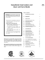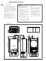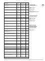
1
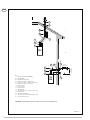
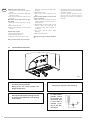
CLIOM-2
“Combi” Gas-Fired
Boiler/Water Heater
Model 35 BF
Installation and
Operating Instructions
315 Oser Avenue • Hauppauge, NY 11788
Tel: (631) 694-1800 • Fax: (631) 694-1832
www.embassyind.com
Fonderie Sime S.p.A.
Via Garbo, 27 – 37045 LEGNAGO (VR)
declares that:
a) The materials used in the interior of the boiler are suitable for the use of drinking water.
b) No dangerous toxic substances were used to manufacture the boiler and its components, which could enter the drinking water.
c) There is no contact zone between drinking water and the water used for the heating system.
déclare que:
a) Les matériels utilisés à l’intérieur de la chaudière sont idoines pour l’utilisation de l’eau potable.
b) Dans la fabrication de la chaudière et de ses composants aucune substance toxique dangereuse n’a été utilisée qui
pourrait s’infiltrer dans l’eau potable.
c) Il n’existe aucune zone de contact entre l’eau potable et l’eau du circuit de chauffage.
Date:
02/03/2009
CLAUDIO MEZZALIRA
Fonderie SIME Spa
Technical Manager
Installation Instruction and
User and Care Guide
ENG
TABLE OF CONTENTS
WARNING: If the information in this manual
is not followed exactly, a fire of explosion may
result causing property damage, personal injury or loss of life.
• Do not store or use gasoline or other flammable liquids or gases in the vicinity of this or
any other appliance.
• WHAT TO DO IF YOU SMELL GAS
• Do not try to light any appliances.
• Do not touch any electrical switches, do
not use any phone in your building.
• Immediately call your gas supplier from
a neighbour’s phone. Follow the gas supplier’s instructions.
• If you cannot reach the gas supplier, call
the fire department.
• Installations and service must be performed
by a qualified installer, service agency or the
gas supplier.
Warning: Do not use this boiler if any part has been
under water. Immediately call a qualified service technician to inspect the boiler and to replace any part of
the control system and any gas control which has been
under water.
Warning: Should overheating occur, or the gas supply
fail to shut off, shut off the gas supply external to the
appliance. Do not switch off the electrical supply to the
pump.
1
DESCRIPTION OF THE BOILER
4
1.1
1.2
INTRODUCTION
DIMENSIONS
4
4
2
INSTALLATION
7
2.1
2.2
2.3
2.4
2.5
2.6
2.7
2.8
2.9
VENTILATION OF BOILER ROOM
INSTALLATION PLATE
CONNECTING UP SYSTEM
SYSTEM FILLING
FLUES/CHIMNEYS
INSTALLATION COAXIAL DUCT
INSTALLATION SEPARATE PIPES
POSITIONING OF OUTLET TERMINALS
ELECTRICAL CONNECTION
7
7
7
8
9
9
9
11
13
3
CHARACTERISTICS
22
3.1
3.2
3.3
3.4
3.5
3.6
3.7
ELECTRONIC BOARD
TEMPERATURE SENSOR
ELECTRONIC IGNITION
SMOKE PRESSURE SWITCH
FLOW SWITCH WATER
HEAD AVAILABLE TO SYSTEM
ELECTRICAL WIRING OF ZONE
HEATING SYSTEMS
22
22
22
23
23
23
4
USE AND MAINTENANCE
24
4.1
4.2
4.3
4.4
4.5
4.6
4.7
4.8
D. H. W. TEMPERATURE ADJUSTMENT
ADJUSTAMENT OF D. H. W. FLOW RATE
GAS VALVE
GAS CONVERSION
DISMANTLING THE CASING
CLEANING AND MAINTENANCE
FAULT FINDING
LOCATION MAIN SHUTOFF VALVE
24
25
25
25
26
26
27
28
5
EXPLODED VIEWS
29
24
3
1
1.1
INTRODUCTION
Celsior boilers are gas-fired thermal appliances for central heating and domestic hot
water production, designed and manufactured to satisfy the needs of multiple dwelling
and modern boiler room requirements. They
comply with ANSI Z21. 13 and CSA 4.9 GAS
FIRED LOW PRESSURE STEAM AND HOT
WATER BOILERS.
These appliances can be fired by both natural
gas and Liquid Propane Gas.
This booklet provides the instructions for the
Celsior with eletronic ignition, modulation, and
direct sealed forced-draught.
The instructions given in this manual are
provided to ensure proper installation and
perfect operation of the appliance.
1. Make sure that there are no liquids or
inflammable materials in the immediate vicinity of the boiler.
2. Make sure that the electrical connections have been made correctly and
that the earth wire is connected to a
good earthing system.
3. Open the gas cock and check the
soundness of the connections, including that of the burner.
4. Make sure that the boiler is set for
operation for the type of gas supplied.
perly installed.
6. Make sure that any shuotff valves are
open.
7. Make sure that the system is charged
with water and is thoroughly vented.
8. Check that the circulating pump is not
locked.
9. Purge the system, bleeding off the air
present in the gas pipe according to
procedures outlined in the local codes
or those having jurisdiction.
10. The installer must provide the user
with instruction in operation of the
boiler and safety devices and hand
over the instruction booklet to the
user.
5. Check that the flue pipe ensuring the
outlet of products of the combustion
is unobstructed and has been pro-
DIMENSIONS: mm (in)
Dimension
R C.H. return
M C.H. supply
G Gas connection
E D.H.W. inlet
U D.H.W. outlet
125
(4.92)
107
(4.21)
60
(2.36)
1.2
IMPORTANT
When carrying out commissioning of the
boiler, you are highly recommended to
perform the following checks:
U
E
Units
C
C
MNPT
C
C
Type 35 BF
3/4” (19 mm)
3/4” (19 mm)
3/4” (19 mm)
1/2” (13 mm)
1/2” (13 mm)
G M R
205 (8.07)
55
(2.17)
55
(2.17)
677 (26.65)
700 (27.56)
ø 60/100
110
(4.33)
41(1.61)
165
(6.50)
22 (0.87)
ENG
DESCRIPTION OF THE BOILER
G
R
450 (17.72)
125
(4.92)
60
(2.36)
335 (13.19)
=
M
E
70 70 70 70
(2.75)
U
=
Figure 1
4
Model 35 BF
Units
Natural gas
Propane
kW
39.2
35.2
But/h
133,800
120,000
kW
23.2
21.3
But/h
79,200
72,700
kW
32.7
31.1
But/h
111,700
106,300
kW
19.6
17.8
But/h
66,900
60,700
l
8.0
8.0
USgal
2.1
2.1
Electric Power consumption
W
165
165
Maximum C.H. pressure
bar
3
3
psi
43.5
43.5
°C
85
85
F
185
185
l
8
8
USgal
2.1
2.1
bar
1
1
psi
14.5
14.5
°C
40-80
40-80
F
104-176
104-176
°C
30-60
30-60
F
86-140
86-140
l/min
15.5
14.7
USgal/min
4.09
3.89
l/min
2.4
2.4
USgal/min
0.63
0.63
bar
0.50
0.50
psi
7.3
7.3
bar
8.6
8.6
psi
125
125
III
III
kg
40
40
lb
88.2
88.2
n°
15
15
Orifice
ø mm
1.30
0.85
Maximum manifold gas pressure
mbar
13.7
24.9
“W.C.
5.5
10.0
mbar
5.0
8.7
“W.C.
2.0
3.5
mbar
16.2
30
“W.C.
6.5
12.0
Maximum input
Minimum input
Maximum output
Minimum output
Water content
Maximum C.H. temperature
Expasion vessel Water content
Expasion vessel Pre-charged
C.H. setting range
D.H.Wsetting range
Continuous D.H.W. flow rate ∆t 30°C
Minimum D.H.W. flow rate
Minimum D.H.W. pressure
Maximum D.H.W. pressure
Vent Category
Weight
Quantity of burners
Minimum manifold gas pressure
Minimum gas supply pressure
CLEARANCES FROM
COMBUSTIBLE MATERIALS:
ENG
Bottom: 0 mm (0 in.)
Sides: 0 mm (0 in.)
Rear: 0 mm (0 in.)
Front: 0 mm (0 in.)
Top: 0 mm (0 in.)
Flue (superate vent): 150 mm (6 in.)
Flue (co-axial vent): 50 mm (2 in.)
CLEARANCES FROM SERVICE
AND PROPER OPERATION:
Bottom: 150 mm (6 in.)
Sides: 150 mm (6 in.)
Rear: 150 mm (6 in.)
Front: 600 mm (24 in.)
Top: 150 mm (6 in.)
MINIMUM CLEARANCES
FROM ELECTRIC METERS,
GAS METERS, REGULATORS
AND RELIEF EQUIPMENT :
US: 4 feet (1.22 m)
CND: 6 feet (1.83 m)
5
ENG
KEY
1 Fan
2 Main exchanger
3 Combustion chamber
4 Gas valve
5 D.H.W. plate exchanger
6 Divertor valve
7 C.H. sensor (SM)
8 100°C safety stat
10 Pump with automatic air vent
11 Expansion vessel
12 Safety valve
13 Boiler discharge
14 Water flow switch
15 Tridicator
16 Automatic by-pass
17 D.H.W. filter
18 C.H. return cock
19 C.H. flow cock
20 D.H.W. cock
21 Gas cock
22 Aqua Guard Filter System
Figure 2
6
5
7
8
4
9
10
3
KEY
1 Control panel
3 Combustion chamber
4 Fan
5 Combustion analysis intakes
6 Negative pressure intake
7 Positive pressure intake
8 Smoke pressure switch
9 C.H. sensor (SM)
10 Main exchanger
11 100°C safety stat
12 Gas valve
13 Flow water switch
14 Divertor valve
15 Aqua Guard Filter System
19
11
13
12
14
1
Figure 3
6
2
INSTALLATION
The installation must conform to the requirements of the Authority having jurisdiction or,
in the absence of such requirement, to the
National Fuel Gas Code, ANSI Z223.1/NFPA 54
and, or CAN/CGAB149 Installation Code. Where
required by the Authority having jurisdiction, the
installation must conform to the Standard for
Controls and Safety Devices for Automatically
Fired Boilers, ANSI/ASME CSD-1. All boilers
must be installed with a proper pressure relief
valve. Pressure relief valves must be installed
to confirm to ANSI/ASME Boiler and Pressure
Vessel Code, Section IV, or CSA B51, as applicable.
If the boiler is installed above the radiation level,
or as required by the Authority having jurisdiction,
the installer must provide a low water cut-off
device at a time of installation. The boiler must be
installed in a fixed location and only by a qualified
installer, service agency or the gas supplier and is
familiar with the requirement that are contained
in this manual. Furthermore, the installation
must be in accordance with current standars
and regulations. The boiler must not be installed
on carpeting. The boiler when used in connection
with a refrigeration system, must be installed so
the chilled medium is piped in parallel with the boiler with appropriate valves to prevent the chilled
medium from entering the boiler. The boiler piping
system of a hot water boiler connected to heating
coils located in air handling units where they may
be exposed to refrigerated air circulation must
be equipped with flow control valves or other
automatic means to prevent gravity circulation of
the boiler water during the cooling cycle. Service
instructions and recommended frequency guidelines periodic examination of venting systems
every six months. Venting systems, the vent-air
intake system, screens in the vent terminal
should be checked and cleaned every six months.
Low water cutoff should be checked and cleaned
every six months. Remove small cover retaining
screw and remove the cover. When the pump
is running and water is flowing around the boiler
, the actuator lifts off the micro switch. Check
that the operation of the actuator ; Ensure that
it is free and that it lifts and returns. If necessary
lubricate the pivot point of the actuator. Flue gas
passageways should be checked and cleaned
every six months. The burner should be checked
and cleaned every six months. Inspect the burner
and if necessary clean using a soft brush and a
vacuum cleaner, taking care not to damage the
front insulation. Check the ignition /ionisation
electrode, check the ignition spark gap (3.5 mm
+/- 0.5 mm) (0.138 in. +/- 0.02 in.). Before reassembly inspect all seals and replace as required.
Furthermore, the installation must be in accordance with current standards and regulations.
2.1
53, Air for Combustion and Ventilation, of the
National Flue Gas Code, ANSI Z 223,1/NFPA
54, or section 7,2, 7.3, or 7.4, of CAN/CGA B
149, Installation Codes, or local codes having
jurisdiction. Where an exhaust fan or any other
air consuming appliance is installed in the same
space as the boiler, sufficient air openings must
be available to provide fresh air when all appliance
are operating simultaneously. It is essential that
in rooms where the boiler are installed at least
as much air can arrive as required by normal
combustion of the gas consumed by the various
appliances. Consequently, it is necessary to make
openings in the walls for the air inlet into the
rooms. These openings must meet the following
requirements:
1. Have a total free section of a least 2225
mm2 every kW (1 in2 for every 1000 Btu/
hr) of heat input, with a minimum of 100
cm2 (15.5 in2);
2. They must by located not more than 18 in
or less than 6 in above the floor level, not
prone to obstruction and protected by a
grid which does not reduce the effective
section required for the passage of air;
3. Where requide by jursdiction or when
required for additional opening must be
provided at the highest elevation practical.
2.2.2
2.2
INSTALLATION PLATE
The installation plate code 6246958 is supplied
with the boiler.
The optional installation plate code 8075416
is supplied with an instruction sheet for the
fixing.
2.2.1 Isolating valves kit
To fit the isolating valves, supplied with the boiler,
use figure 4 for assembly.
ENG
The follow is available to facilitate water and gas
connection of the boiler with the heating system:
for assembly of the unions to see fig. 1.
2.3
CONNECTING UP SYSTEM
To protect the heat system from damaging corrosion, flakes or deposits, before installation it is
extremely important to clean the system using
suitable products such as, descaler or slug removing solution. For long-term protection against
corrosion and deposits, the use of inhibitors is required for new installations and after cleaning the
system. It is important to check the concentration
of the inhibitor after each system modification and
during maintenance following the manufacturer’s
instructions (specific tests are available at your
dealer). The safety valve drain must be connected
to a collection funnel to collect any discharge during interventions. If the heating system is on a
higher floor than the boiler, install the on/off taps
supplied in kit on the heating system delivery/return pipes.
WARNING: Failure to clean the heat system or
add an adequate inhibitor invalidates the device’s warranty.
2.3.1
With a hermetically sealed combustion chamber
and air supply circuit from outdoors, may be
installed in any room in the home. Keep boiler
area clear and free from combustible materials,
gasoline and other flammable vapors and liquids.
System connection unions
Gas Requirements
Read the date plate to be sure the water heater is made for the type of gas being used.
An adhesive data plate is stuck inside the front
panel, it contains all the technical data identifying the boiler and the type of gas for which
the boiler is arranged. If the information does
not agree with the type of gas available, do not
install or operate the water heater. Call your
dealer. The gas piping must be installed according to all local and state codes, or in absence
of local and state codes, with the latest “Natural gas and propane installation code”, CAN/
CSA-B 149.1 or “National Flue Gas Code”,
ANSI Z223.1 (NFPA 54). Consult the “Natural
gas and propane installation code” or “National Flue Gas Code” for the recommended gas
R
M
G
E
U
C.H. return
C.H. supply
Gas connection
D.H.W. inlet
D.H.W. outlet
VENTILATION OF BOILER ROOM
When using air from the boiler room, an adequate air supply shall by provided for combustion of this boiler. An insufficient supply can
result in poor combustion and possible sooting
of the burner, combustion chamber or flue
passageway. The boilers installed using inside air
supply must provide provisions for Combustion
Air and Ventilation Air in accordance with section
Figure 4
7
ENG
pipe size of other materials. The sections of the
piping making up the system must be such as to
guarantee a supply of gas sufficient to cover the
maximum demand, limiting pressure loss between the gas meter and any apparatus being used
to not greater than:
1. 1.2 mbar (0.5”W.C.) for supply pressures under 17 mbar (7”W.C.);
7 6
8
2. 2.5 mbar (1.0”W.C.) for supply pressures
from 17 mbar (7”W.C.) to 35 mbar (14”W.C.).
2.3.2
Filter on the gas pipe
The gas valve is supplied by the factory with an
inlet filter, which, however, is not adequate to
entrap all the impurities in the gas or in gas
main pipes.
To prevent malfunctioning of the valve, or in certain cases even to cut out the safety device with
which the valve is equipped, install an adequate
filter on the gas pipe. In any case, a sediment
trap must be installed upstream of the gas
controls.
2.4
SYSTEM FILLING
Filling of the boiler and the system is done by
installing a pressure reducing valve. The charge
8
5
1 3 2
KEY
1 D.H.W. inlet/outlet manifold
3 D.H.W. filter
4 By-pass
5 Water rate adjuster
4
9
6
7
8
9
D.H.W. exchanger
Microswitches
Water flow switch
Boiler discharge
Figure 5
x
2
4
y
3
min 4.27 - max 16.4 ft
min 1,3 m - max 5 m
min 1,3 m - max 5 m
Gas connestions must be made in accordance
with current standards and regulations. When
dimensioning gas pipes from the meter to the
boiler, both capacity volume (consumption) in
m3/hr (ft3/hr) and gas density must be taken
into account. The boiler and the boilers gas connection must be leak tested before it is put in to
operation. The boiler and its individual shut-off
valve must be disconnected from the gas supply piping system during pressure testing of the
system at pressures in excess of 1/2 psi (3.5
kPa). The boiler must be isolated from the gas
supply piping system by closing its individual manual shut off valve during any pressure testing of
the supply piping system at test pressures equal
to or less than 1/2 psi (3.5 kPa). The boiler shall
be installed such that the gas ignition system
components are protected from water (dripping,
spraying, rain etc.) during boiler operation or service (circulators or control replacement etc.). The
boiler and its gas connection must be leak tested
before placing the the boiler is put into operation.
Use a chloride-free soap and water solution (bubbles forming indicate a leak) or other approved
method. After placing the boiler in operation, the
ignition system safety shutoff device must be tested.
To testing the system:
- Close the gas valve (gas cock)
- feed to boiler
- initiate a call for heat (see user instructions)
- verify red led “Ignition lock-out” light is on, after
ignition boiler.
- reset boiler by rotating the function knob to
chimney sweep and stay at least one second,
and after back to “winter” or “summer” position.
- finally open the gas cock.
7
6
2
3 8
C42
C32
x + y = max 3,5 m "25"
x + y = max 3,0 m "30-35"
IMPORTANT:
– Each additional 90° curve (code
8095801) installed reduces the available length by 0.90 metres (3 ft).
– Each additional 45° curve installed
reduces the available length by 0.45
metres (1.5 ft).
– It is advisable to assemble the condensation collector (8) on vertical segments exceeding 2.5 metres (8.2 ft) in
length and to limit maximum length to
4 metres (13.1 ft).
13.1 ft
maxmaximum
3,5 m "25"
max
m
max 3,0
m 4.0
"30-35"
C12
2
1
KEY
1 Coaxial flue kit L. 810 mm (32 inch) code 8084811
2 a Extension L. 1000 mm (39.4 inch) code 8096103
2 b Extension L. 500 mm (19.7 inch) code 8096102
3 Vertical extension L. 200 mm (7.9 inch) code 8086908
6 Articulated tile code 8091300
7 Roof outlet terminal L. 1284 mm (50.6 inch) code 8091200
8 Vertical condensation collector L. 200 mm (7.9 inch) cód. 8092803
Figure 6
pressure, with the system cold, must be between 1 and 1.2 bar (14.5 and 17.4 psi). During
system filling you are recommended to keep the
main switch turned OFF. Filling must be done
slowly so as to allow any air bubbles to be bled off
through the air valves. Should the pressure have
risen well above the limit expected, discharge
the over pressure by opening the pressurerelief valve. Bleed pump by loosen plug at back
of motor. Once air is removed re-tighten plug. It
may be necessary to free the pump motor before filling the system. This is done by removing
the pump plug and turning the pump shaft loose.
Do not forget to re-tighten pump plug before
filling system.
See typical piping in the figure below.
2.4.1
Emptying the system (fig. 5)
2.5.1
Passing flue pipes through
an existing chimney
When renovating or passing flue pipes through an
existing chimney, use only flues which are declared suitable for the purpose by the manufacturer,
following the instructions for installation and use
provided by the manufacturer.
2.6
INSTALLATION COAXIAL PIPE (fig. 6)
The air inlet-smoke outlet assembly ø 60/100
is supplied in a kit code 8084811 complete with
mounting instructions.
With the curve supplied in the kit the maximum
horizontal length of the flue must not exceed 4
m (13 ft).
The diagrams in fig. 6 illustrate a number of examples of different coaxial outlets.
2.6.1 Coaxial flue diaphragm (fig. 6/a)
Use the drain tap to empty the system (9).
Turn off the boiler before doing this.
2.5
FLUES/CHIMNEYS
The flue or chimney used to release the products of combustion into the atmosphere must
comply with current standards and regulations.
Horizontal vent lengths must be supported
every I meter (39 in) or less to prevent sagging.
The boiler is supplied as standard with a ø
86 diaphragm. With outlet type C12, install
diaphragm ø 84 mm (3.3 inch) only if the coaxial
flue is less than 1 metres (3.3 ft) long.
For C32 discharge options, it is necessary to
order the optional diaphragm separately and use
it in accordance with the instructions provided in
figure 6/a.
2.7
INSTALLATION SEPARATE PIPES
ENG
The smoke pipe must be certified ø 3” category III venting. When installing the pipes, follow
closely the requirements of the current standards and regulations, as well as the following
practical pointers:
1. With direct intake from outside, when the
pipe is longer than 1 m (3.3 ft), you are
recommended to insulate the piping so as
to prevent formation of dew on the outside of the piping during particularly hard
periods of the year.
2. With the outlet pipe outside the building or
in cold indoor environments, insulation is
necessary to prevent burner failure during
trial for ignition. In such cases, provide
for a condensate-collector system on the
piping.
3. If a segment of the flue passes through a
flammable wall, this segment must be insulated with a glass wool pipe insulator 30
mm (1 in) thick, with a density of 50 kg/
m3 (3lb/ft3) or follow vent manufacturers
instructions for clearances to combustibles.
TYPICAL PIPING
HOT
WATER
SUPPLY
COLD
WATER
SUPPLY
COLD WATER
SUPPLY
BOILER LOOP
LOW
TEMPERATURE
LOOP
HIGH
TEMPERATURE
LOOP
9
ENG
4. The distance between the intake air and
the smoke pipe must be within 300 mm
(12 in) - (see fig. below).
5. The head loss of the smoke pipe cannot
exceed by more than 4.8 mm (0.19 in)
of the intake head loss.
6. Outlet terminal must be flush with the
wall and the inlet terminal must protrude at least 50 mm (2 in) from the
outstide wall (see fig. below).
The maximum overall length of the intake
and exhaust ducts depends on the head
losses of the single fittings installed and
must not be greater than 12 mm H2O
(0.472 “W.C.).
(ATTENTION! The total length of linear
exhaust sections should not exceed 8 m
(26 ft) as compared to the total length of
linear suction sections).
For head losses in the fittings, refer to Table
1 and example fig. 7.
Slanted view
With outlet type C12, install diaphragm ø 84 mm/3.3 inch only if the coaxial flue is
less than 1 metres (3.3 feet) long.
With outlet type C32, use the following diaphragms, depending on flue length and without
any additional curves:
Installations with vertical
Installations with vertical condensation
extension L. 200 mm/7.9 inch code 8086908
collector code 8092803
Diaphragm
Diaphragm
Without
Diaphragm
None
ø 86/3.4”
ø 87.5/3.44”
diaphragm
ø 87.5/3.44”
diaphragm
(cod. 6028623) (cod. 6028624)
(cod. 6028624)
L min = 1,3 m L min = 2,5 m L min = 4 m
L min = 2,5 m
4.27 ft
8.2 ft
13.1 ft
8.2 ft
L max = 2,5 m
8.2 ft
L max = 4 m
13.1 ft
L max = 5 m
16.4 ft
L max = 2,5 m
8.2 ft
L max = 4 m
13.1 ft
Figure 6/a
TABLE 1
Vent Accessories ø 3”
45° curve MF
90° curve MF
Extension L. 1000 mm/39.4 inch (horizontal)
Extension L. 1000 mm/39.4 inch (vertical)
Terminal 1 (Termination box : 2SVSRTF)
Terminal 2 (Termination hood : 2SVSHTX)
Intake terminal
Manifold
Roof outlet terminal L.1390
Condensation collection T
Frontal view
Load loss in mm H2O (“W.C.H2O)
Intake
0.6 (0.024)
0.65 (0.026)
0.3 (0.012)
0.3 (0.012)
------------0.2 (0.008)
0.3 (0.012)
-------------
Outlet
0.3 (0.012)
0.5 (0.020)
0.13 (0.005)
0.06 (0.002)
0.8 (0.0315)
0.6 (0.0236)
------------------1.1 (0.043)
Roof outlet/Intakes
------------------------------------------------0.6 (0.024)
-------
Example of allowable installation calculation in that the sum of the head losses of the single fittings
is less than 7.0 mm H2O (0.276 “W.C.H2O):
Intake
Outlet
23ft horizontal pipe ø 3” mm x 0.30
2,1
--–-23ft horizontal pipe ø 3” x 0.13
--–-0,91
n° 2 90° elbows ø 3” x 0.65
1,3
--–-n° 2 elbows 90° ø 3” x 0.50
--–-1,0
n° 1 terminal ø 3”
0,2
2,0
Total head loss
3,6
+
3,91 = 7,51 mmH2O
(0.296 “W.C.H2O)
With this total head loss, remove the segments from n. 1 to n. 9
from diaphragm in the intake pipe.
Figure 7
10
Separate flue kit (fig. 8)
1
6
110
3
165
2
100
(3,94”)
100
(4.33”)
ø 80 (ø 3“)
205 (8.07”)
K
92
(6.5”)
165
4
(3.62”)
The separate flue kit code 8089909 is supplied with an intake diaphragm which must
be used as shown in fig. 8/a, depending on
the maximum load loss permitted in both
flues. To use the air intake in this type of
outlet you must perform the following operations (fig. 9):
1 Remove the base of the air intake, using
a tool to cut it off (a);
2 Overturn the air intake (b) and replace
the seal (5) with the seal supplied in the
kit code 8089909;
3 Insert the intake diaphragm supplied in
the kit code 8089909, pushing it in until
it is in contact with the bottom bead.
You can now insert the extension or curve
in its housing to complete the intake. You
need not use any seal or sealant, as gasket
provided is sufficient.
ø 80 (ø 3“)
ENG
(6,5”)
2.7.1
2.7.2 Outlet systems
The diagrams in fig. 9/a illustrate a number of examples of different types of separate outlets.
2.8
POSITIONING OF OUTLET
TERMINALS (fig. 11)
KEY
1 (ø 125/95 mm - ø 4.92/3.74 inch) sponge seal
2 Fixing screw
3 Flue outlet flange
4 Inlet air diaphragm
6 Manifold with intakes
The outlet terminal must be flush with the
wall and the inlet terminal must protrude
50 mm (2 in) from the outstide wall at
least.
N° segments to remove
n° 1 and 2
from n° 1 to 3
from n° 1 to 4
from n° 1 to 5
from n° 1 to 6
from n° 1 to 7
from n° 1 to 8
from n° 1 to 9
from n° 1 to 10
without diaphram
Figure 8
Load loss (mm H2O)
0 - 1.0
1.0 - 2.0
2.0 - 3.0
3.0 - 4.0
4.0 - 5.0
5.0 - 6.0
6.0 - 7.0
7.0 - 8.0
8.0 - 10.0
10.0 - 12.0
(“W.C.H2O)
0 - 0.039
0.039 - 0.079
0.079 - 0.12
0.12 - 0.16
0.16 - 0.20
0.20 - 0.24
0.24 - 0.28
0.28 - 0.31
0.31 - 0.39
0.39 - 0.47
Figure 8/a
a
IMPORTANT: The three housings
on the diaphragm permit assembly of the air intake in one position
only.
b
5
Figure 9
11
ENG
11
10
9
11
3
3
2
1
10
7
3
C42
8
2
1
3
3
3
12
1
6
3
2
8
C52
B52
3
6
3
3
1
5
4
KEY
1
2a
2b
3a
3b
3c
4
5
6
7
8
9
10
11
12
Separate flue kit code 8089909
90° elbow MF
Isolated 90° elbows MF
Extension L. 1000 mm (39.4 inch)
Insulated extension L. 1000 mm (39.4 inch)
Extension L. 500 mm (19.7 inch)
Outlet terminal
Int.-est. ring kit
Intake terminal
45° elbow MF
Condensation outlet L. 135 mm (5.31 inch)
Doubler fitting
Tile with articulated joint
Roof outlet terminal L. 1390 mm (54.7 inch)
Tee condensation outlet
max 0,5 m
2
C82
B22
0,3 m
(12inches)
max
0,5 m
3
1
C12
B52
0,3 m
(12inches)
C32
6
IMPORTANT: In type C52 the outlet and inlet flues must not come out on opposite walls.
Figure 9/a
12
Outlet terminals for forced draft systems
may be located on the outer walls of
the buildings. Table 2 shows approximate,
non-binding minimum distances to be met
for a building of the type shown in fig. 5.
Please refer to local codes for minimum
clearances.
2.9
ELECTRICAL CONNECTION
The boiler must be electrically bonded to
ground in accordance with the requirements of the Authority having jurisdiction
or, in the absence of such requirements,
with the National Electrical Code, ANSI/
NFPA 70 and or the Canadian Electrical
ENG
To install the tubes in such way protect the
building materials from degradation by fluegas.
TABLE 2
MINIMUM DISTANCE
mm
feet
A
B
C
D
E
F
G
H
I
L
900
900
300
300
900
900
300
300
300
3
3
1
1
3
3
1
1
1
2100
600
600
7
2
2
2000
3000
6.56
9.84
-
MNOP -
below openable window or door
below ventilation opening (non mechanical)
below eaves
below balcony
from adjacent window or door
from adjacent ventilation opening (non mechanical)
from horizontal or vertical soil or drain pipes (2)
from corner of building
from recess in building
above a paved sidwalk or a paved driveway that is
located on private property
between two terminals set vertically
between two terminals set horizontally
from a surface facing without
openings or terminals
as above but with openings and terminals
1. The vent shall not terminate;
a) directly above a sidewalk or paved driveway that is located between two single - family dwellings and
severs both dwellings;
b) less that 2.1m (7 ft) above a paved sidewalk or a paved driveway that is located on public property;
c) within 1.8 m (6 ft) of a mechanical air-supply inlet to any building;
d) above a meter and regulator assembly within 1.8 m (6 ft) horizontally of the vertical centerline of
the regulator vent outlet to a maximum vertical distance of 4.5 m (15 ft);
e) within 1.8 m (6 ft) of any gas service regulator vent outlet;
f) less than 300 mm (1ft) above grade level plus expected snow level;
g) within 900 mm (3 ft) of a window or door that can be opened in any building, of any non-mechanical
air supply inlet to any building, or of any combustion air inlet of any other appliance;
h) Underneath a veranda, porch, or deck unless;
i) the veranda, porch, or deck is fully open on a minimum of two sides beneath the floor;
ii) the distance between the top of the vent termination and the underside of the veranda, porch, or
deck is greater that 300 mm (1ft).
2. When setting terminals, where materials that may be subject to the action of the combustion products
are present in the vicinity, e.g., eaves, gutters and downspouts painted or made of plastic material,
projecting timberwork, etc., distances of not less than 1.5 m (5 ft) must be adopted, unless adequate
shielding is provided to guard these materials.
Fig. 11
13
ENG
2.8.2
Instructions special stainless
steel venting system for use
with Category III appliances
TERMINATION HOOD
Z-FLEX recommends that an experienced professional who works with venting systems on
a regular basis perform the installation. These
instructions are intended as a guide to assist
a professional installer.
When the Z-VENT system is installed, the
following should be observed:
1. A venting system that exits the structure
through a sidewall or the like, shall terminate not less than 12 inches (254 mm)
above the ground (see figure 6/a, page
22).
2. The termination of a system shall be located above the snow line in geographical
areas where snow accumulates. The termination area should be kept clear of snow
and ice at all times.
3. The vent shall not terminate less than 7 ft.
(2.13 m) above a paved sidewalk or driveway.
4. The termination shall be 6 ft. (1.8 m) or
more from the combustion air intake of
any appliance.
5. The system shall terminate more than 3 ft.
(0.91 m) from any other building opening,
gas utility meter, service regulator or the
like.
14
6. Exterior mounted venting systems should
be enclosed below the roof line with a
chase to limit condensation and protect
against mechanical failure.
NOTES:
A. The Z-FLEX SPECIAL STAINLESS VENT
SYSTEM is for use only with appliances
having a positive vent pressure of 8” of
water column or less.
B. Except for installation in one and two family
dwellings, a venting system that extends
through any zone above that on which the
connected appliance is located shall be
provided with an enclosure having a fire
resistance rating equal to or greater than
that of the floor or roof assemblies through
which it passes.
SVSHTX03
runs must use firestops as lateral support
at each ceiling level and at least one support collar at the base of the vertical run.
For vertical runs exceeding 16’ (4.88 m), a
support collar is required at 16’ (4.88 m)
intervals.
Horizontal runs require a loose fitting metal
strap or similar support at each joint.
F. Examine all components for possible shipping damage prior to installation.
G. Proper joint assembly is essential for a
safe installation. Follow these instructions
exactly as written. Check severeness of
joints upon completion of assembly.
H. Check for unrestricted vent movement
through walls, ceilings and roof penetrtions.
C. Do not place any type of insulation in any
required air spaces surrounding the venting
system.
I. Different manufacturers have different joint
systems and adhesives. Do Not Mix Pipe,
Fittings or Joining methods from different
manufacturers.
D. A termination must be used on all installations to assure proper operation and to
prevent debris from entering the venting
system.
Joint procedure
(see figure 6 below)
E. The Z-Vent system must be free to expand
and contract.
Pipe must be properly supported. Vertical
The female end of each Z-Vent III component
incorporates a silicone sealing gasket.
Examine all components to insure that gasket
integrity has remained during shipping.
Gaskets must be in the proper position or flue
gases could leak resulting in carbon monoxide
poisoning.
1. Align pipes and push them together as far
as they will go (to indent or at least 1.75
inches).
2. Tighten gear clamp to a minimum torque
of 40 in/lbs. and a maximum of 50 in/lbs.
NOTE: Some flue collars may require the use
of high temperature silicone sealant to make
a positive pressure gas tight seal.
Side wall venting installation
ENG
15
ENG
(see figure 6/a below)
1. Penetrating a combustible wall requires
the use of a wall thimble.
The pipe may be mortared in directly
without using a wall thimble, if the wall is
non-combustible. Install wall thimble into
wall, observing the aforementioned rules
and/or local building codes.
Select the point of wall penetration where
the minimum 1/4 “ per foot of slope (6.4
mm-0.25 in. per 305 mm-12 in.) can be
maintained.
A framed opening is required to insert the
thimble halves.
The thimble is adjustable for different wall
thicknesses.
Caulk around outside edge of plates as
necessary and fasten to wall using suitable
screws or nails.
The vent pipe must be sealed at wall
thimble as per code regarding continuous
vapor barrier.
2. The system can now be assembled through
16
the thimble (attach the termination first
- note “UP” arrow) and then back to the
appliance as per illustration using JOINT
PROCEDURE as described on page 21.
A gear clamp (or locking band) must be
installed around the pipe on the inside of
wall to trap pipe in position so that the
system cannot be moved in or out of wall.
This applies to both combustible and noncombustible walls.
3. The system must be supported along its
horizontal length at all elbow locations
and joints (every forty-eight inches or less)
using straps around pipes maintaining
clearance to combustibles as per table on
page 21.
Any horizontally installed portion of a venting system shall have a slope (upwards
for Category II, III, or IV appliances or
downwards for Category III or IV appliances) not less than 1/4” (6.4 mm) every 12
inches (305 mm) to prevent collection of
condensate at any location in the assem-
bly. Fasteners must not penetrate the
components of the system either when
joining pipes and fittings or using support
straps.
The lengths of pipe may be cut on nonexpanded end using aviation snips or a
hacksaw (24 tpi).
The cut end must be filed or sanded
smooth before joining. When installing the
condensate tube be sure to form a trap by
means of a 3” (76.2 mm) loop filled with
water.
This tube must be 3/8” (10 mm) ID high
temperature silicone for at least the first 6
inches (152 mm) and attached with a gear
clamp or hose clamp. The effluent must be
disposed of according to local regulations.
NOTE: Z-FLEX recommends using a neutralizer kit when using a condensate trap. A condensate pump may be required.
Vertical venting
(see figure 6/b - 6/d)
NOTE: The vent termination must be at least
3 ft. (1 m) to a maximum of 6ft. above the roof
line and 2 ft. (.61 m) higher than any part of a
structure within 10 ft. (3.1 m). The total vertical distance of the vent system from appliance
flue collar to the rain cap termination and the
maximum length of offsets shall not exceed
that specified in the appliance manufacturer’s
installation instructions. No continuous vertical run shall be longer than sixty feet (18.3 m).
All horizontal sections must observe the rules
for HORIZONTAL VENTING. The clearance to
combustibles inside a chase shall be no less
than 4” (100 mm).
1. Prior to beginning the installation loosely
assemble all parts required to make sure
all parts are present.
2. Locate position for venting system and
proceed to cut holes for firestop support
and firestop spacers. All vertical installations require the use of a support. Frame
the opening of the floor using lumber,
which is dimensionally consistent with the
structural members. Insert the support
from beneath the framed opening and
secure with nails or screws as required.
3. Refer to JOINT PROCEDURE (figure 6)
before assembling system.
7. Attach rain cap using.
PROCEDURE (figure 6)
4. Install system joining pipe as required
up through roof (illustration page 25).
Tighten gear clamp on firestop support to
hold vent system. NOTE: A firestop must
be provided when a vent passes through
a combustible floor or ceiling. The opening
must be framed for the support since the
support also serves as a firestop.
8. The vertical section is connected by an
elbow joined to the horizontal run and
then through a drain tee (see page 4
for details) to the appliance. Elbows
are joined to pipe using the JOINT
PROCEDURE (figure 6).
5. The roof flashing can now be installed.
Where the vent passes through the roof
a flashing must be used to maintain the
required clearances and to protect from
the elements. The framed opening must
be large enough to provide the necessary
clearances to combustibles, taking into
account the slope of the roof. The flashing
can be used on slopes from flat to 6/12
pitch. Install the flashing while holding the
pipe centered in the opening. Fasten the
flashing to the roof under the roofing
material upslope from the pipe and above
the roofing material below the pipe. Seal as
required using high temperature silicone.
JOINT
ENG
NOTE: If there is no solid anchor point
in the system below the roof (ie Firestop
Support etc.) then a Z-Vent Guy Band must
be used below the roof as follows. (see
figure 6/c)
a. Attach the Guy Band at any point above
an elbow or tee in the vertical section
within 20 feet of the roof.
b. Fasten stainless steel or galvanized
cable with a minimum capacity of 500
lbs. to each of the four anchor holes.
c. Anchor the cables to a rigid building
member using an appropriate fastening
method.
Above the roof
(see figure 6/c)
6. Install Top Support around pipe and against
flashing collar. (figure 6/b, 6/d, 6/e,
6/c)
17
ENG
18
NOTE: When Z-Vent must be extended above
the roof line more than six (6) feet the Guy
Band must be used to support the system.
1. Install the Guy Band below the Rain Cap
using the 10-24 screw and nut provided.
2. Attach stainless steel or galvanized cable
with a minimum rated capacity of 500 lbs
(227 kgf) to each of the four anchor holes.
3. Anchor the cables to a rigid building
member using an appropriate fastening
method.
Existing masonry chimney
(See figure 6/e)
NOTE: A masonry chimney flue may be used
to route Z-VENT if no other appliance vents
directly into the same flue without a liner. Prior
to beginning the installation, be sure that the
existing chimney meets all national and local
building codes. The chimney must be cleaned,
removing all soot, debris and creosote before
installing Z-VENT.
1. Using the JOINT PROCEDURE, (figure 6)
join pipe lengths as they are lowered down
the chimney until bottom end lines up with
opening in chimney. (A rope may be used
to facilitate lowering of pipe).
2. Install flashing over last pipe length and
attach top support to pipe. Leave 6” (150
mm) of pipe protruding from flashing so
that rain cap may be installed and to allow
for any adjustment to line up base tee properly.
3. Fasten flashing to chimney top using
caulking and/or screws. If the top clay tile
is still in place, the corners of the flashing
must be notched and flashing plate formed
down around clay tile.
4. The rain cap may now be installed using
the JOINT PROCEDURE (figure 6).
5. Where required a drain tee should
be installed to a pipe as per JOINT
PROCEDURE (figure 6).
ENG
6. The remainder of the horizontal installation
to the appliance can be done the same as
for side wall venting on page 22 observing
rules for HORIZONTAL VENTING.
7. Final adjustment may be made to the top
support if necessary.
19
ENG
Code Part I, CSA C22.1, Electrical Code. If
you must replace the electric power cable
supplied with the boiler, order it exclusively
from Sime.
The power supply must be single-phase 120
V-60 Hz througth a main switch protected by
a fuse with a distance of a least 3 mm (0.118
inch) between contacts.
NOTE: The boiler must be connected with an
efficient grounding system. SIME shall not
be held liable for injury or damage resulting
from failure to ground the boiler.
2.9.1
Electrical panel (fig. 12)
Before performing any kind of operation,
disconnect the unit by unpluging the power
cord.
Placing the boiler selector in position “OFF”
does not disconnect the electric board from
the power supply.
Caution: Label all wires prior to disconnecting wires when servicing control. Wiring
errors can cause improper and dangerous
operation.
After connecting all wires, verify proper operation after servicing.
Remove the three screws (9) locking the control panel in place and pull the panel forward
until it can be tilted downward.
To access the components of the electrical
panel, unscrew the four screws holding the
protective guard in place (6).
2.9.2
Room stat connection (fig. 12)
To gain access to connector “TA”, remove
the control panel cover (7) and connect the
room stat to the terminals 15-16 after having
removed the jumper.
The thermostat or timer-thermostat,
recommended for better room temperature
control, must be dry contact.
IMPORTANT: Before performing any kind of operation,
disconnect the unit from the
power supply using the bipolar switch of the plant. Placing
the boiler selector in position
“OFF” does not disconnect the
electric board from the power
supply.
ATTENTION: After having removed
the three screws, slide the panel
outward to tilt it downward.
9
6
7
4
1
KEY
1
2
4
5
6
7
8
9
20
Tridicator
Time programmer seet (optional cod. 8092214)
Main PCB
Earth ground
Control panel protection
Cover (TA)
Connector (TA)
Fixing screw
2 5
8
Figure 12
2.9.3
Wiring diagram
ENG
CN6
CN2
CN7
120V
60Hz
CONNECTOR SPARE PART CODES:
CN2 code 6299909
CN6 code 6299906
CN7 code 6299907
KEY
F
PI
EV1-2
V
PF
VP
M
SM
SS
TA
EAR
Fuse (1.6 AT)
C.H. pump
Gas valve coil
Fan
Smoke pressure switch
Divertor valve
Modulator
C.H. sensor
D.H.W. probe
Room stat
Ignition/detection electrode
TRA
TS
PA
FL
TF
OP
Ignition transformer
100°C (212°F) safety stat
Water pressure switch
Flowmeter
Smokes stat
Time programmer
Nota: The room stat or the programmable
thermostat must be connected to terminals
15-16 of the “TA” connector after having
removed the bridge.
Figure. 13
21
3
ENG
3.1
CHARACTERISTICS
ELECTRONIC BOARD
The electronic boards are manufactured in
compliance with the ANSI and Canadian directives.
They are supplied with 120V and, through a built-in transformer, send a voltage of
24V to the following components: modulator, D.H.W./C.H. sensors, room stat, water
flowmeter/water pressure switch, pressure
switch valve, flue gas thermostat/flue gas
pressure switch, safey thermostat and time
programmer.
An automatic and continuous modulation
system enables the boiler to adjust the heat
output to the various system requirements or
the User’s needs.
The electronic components are guaranteed
against a temperature range of 0° to
+60°C (32°-140° F)
3.1.1
Bi-colour green led off if power is cut-off.
Bi-colour orange led: C.H. sensor (SM) fault.
Green led flashing: fan/smoke pressure switch/smoke stat failure.
Orange flashes on water circulation.
Flashing red led indicates a problem in the tap water probe (SS)
Red led on, ignition blocked/safety stat tripped:
turn the rotary switch in the position ( )
to restore functioning
Fault finding
Figure 14
The indicator leds signalling irregular and/
or incorrect operation of the equipment are
indicated in fig. 14.
rations described above be carried out by
authorized technical staff.
3.1.2
3.2
Devices
The electronic board is equipped with the
following devices (fig. 15):
Antifreeze system made up of the NTC heating sensor that activates when the water
temperature reaches 6°C (43 F).
The sensor acts as a limit stat, switching-off
the burner when the temperature measured
is higher than 85°C (185 F); the reset temperature is set at 80°C (176 F).
When sensor has tripped, the boiler will not
– Connector “METANO-GPL” (4)
With the connector disconnected, the boiler
is ready to function with METHANE; with the
connector connected with GPL.
ATTENTION: It is essential that the ope-
2
TEMPERATURE
SENSOR
Temperature
°C
°F
20
68
30
86
40
104
50
122
60
140
70
158
80
176
Resistance
(Ω)
12.090
8.313
5.828
4.161
3.021
2.229
1.669
3
7
8
9
5
function for either service.
Table 3 shows the resistance values ( ) that
are obtained on the sensor as the temperature varies.
TABLE 3
4
KEY
1 Jumper JP2
2 Fuse (1,6 AT)
3 D.H.W. potentiometer
4 Connector “METHANE/GPL”
5 Rotay switch
7 Block red led
8 C.H. potentiometer
9 Bi-colour led gree/orange
10
Connector “TA”
1 10
Figure 15
22
3.3
ELECTRONIC IGNITION
ENG
Ignition and flame detection is controlled by
an electrode located on the burner. These
guarantee maximum safety with intervention
times, for accidental switching off or gas failure, of within one second.
3.3.1
Operating cycle
Rotate the rotary switch to summer or winter,
the red led should light up.
Burner ignition normally takes place within 10
seconds. However, it is possible for ignition failures to occur, with consequent activation of signal
indicating that the control box has “locked out”.
Figure 16
– Gas failure
The control box runs through the cycle normally sending electric power to the ignition
electrode. The electrode continues spark
discharge for a maximum of 10 sec. If the
burner does not ignite, the control box “locks
out”.
This may occur upon first ignition or after long
periods of boiler lay-off when there is air in the
pipes. It may be caused by the gas cock being
closed or by one of the valve coils having a
break in the winding, so that the valve cannot
open.
nected as shown in fig. 16.
3.5
FLOW SWITCH SAFETY VALVE
The electrode is earthed or very worn and
needs to be substituted. The control box is
defective.
The flow switch (8 fig. 5) is tripped and stops
the burner when it does not detect water flow
in the primary circuit > 400 l/h (1.76 USgpm).
To restore burner functioning, check system
pressure and the functioning of the pump and
the flow switch, and the cleaning of the “Aqua
Guard Filter System” filter.
NOTE: If replacing the flow switch valve, make
sure that the arrow stamped on the valve
points in the same direction as the flow of
water.
When there is a sudden voltage failure, the burner shuts out immediately; when power supply
returns, the boiler will start up again automatically.
3.4
– Ignition electrode fails to spark
In the boiler, only the gas to the burner is seen
to open. After 10 sec. the control box “locks
out”.
This may be due to a break in the wire of the
electrode or to the wire not properly fastened
to the electric terminal of the ignition transformer.
SMOKE PRESSURE
SWITCH
(fig. 16)
The pressure switch with fixed settings: 4.6-5.6
mmH2O (0.18-O.22 ”W.C.H2O), is able to guarantee the boiler operation even with air intake
and smoke outlet pipes at the maximum limit of
the length allowed.
The value of the signal to the pressure switch
is measured by means of a manometer con-
3.6
HEAD AVAILABLE TO SYSTEM
Residual head for the heating system is shown
as a function of rate of flow in the graph in fig.
17.
RESIDUAL HEAD VERSUS FLOW FOR HEATING SYSTEM
FLOW RATE [USgpm]
0
1
2
3
4
5
600
BY-PASS ON
BY-PASS OFF
20
15
400
300
10
RESIDUAL HEAD [ft]
RESIDUAL HEAD [mbar]
500
200
5
100
0
0
0
200
400
600
FLOW RATE [l/h]
800
1000
1200
Figure 17
23
ENG
To obtain the maximum head available to the
system, turn off the by-pass by turning the
union to the vertical position (fig. 17/a).
3.7
ELECTRICAL WIRING
OF ZONE HEATING
SYSTEMS
By-pass
off
By-pass
escluso
When installing a system of this type, use a
separate electrical line to which room thermostats with their local valves will be connected.
Connect micro switches or relay contacts on
terminals 15-16 of the “TA”connector of the
electronic card after removing the existing
jumper (fig. 18).
By-pass
inserito
By-pass
on
Figure 17/a
L
Connettore
"TA"
“TA” connector
TA
VZ
R
TA1
VZ1
R1
N
KEY
TA-TA1
VZ-VZ1
R-R1
CR-CR1
NOTE: Relays are used only if the
area valves have no microswitches.
Zone room stat
Zone valve
Zone relay
Relay contact or micro zone valve
CR
CR1
Figure 18
4
USE AND MAINTENANCE
4.1
D.H.W. TEMPERATURE
ADJUSTMENT
The system with a potentiometer for adjusting
the temperature of D.H.W. with a setting
range from 30° to 60°C (86-140 °F) offers a
double advantage:
1) The boiler adapts perfectly to any type of
D.H.W. system, whether the mixing system
is a mechanical or a thermostat-controlled
type.
24
2) The thermal output is dosed according to
the temperature required, which means a
considerable saving in fuel.
NOTE: In order to avoid any misunderstanding
please remember that the value obtained by
the product of temperature difference (in °C)
between D.H.W. output and input into the
boiler by the hourly flow rate measured on the
tap, where hot water is drawn off (l/h), cannot
be higher than the useful output developed by
the boiler.
For measurements and checks on flow rate
and temperature of D.H.W., use suitable
instruments, taking into consideration any
heat dispersion along the stretch of piping
between the boiler and the measuring point.
4.2
ADJUSTMENT OF
D.H.W. FLOW RATE
To adjust the D.H.W. flow rate, use the flow rate
adjuster (5 fig. 5).
Remember that the flow rates and corresponding temperatures of use of hot water have
been obtained by positioning the selector of the
circulation pump on the maximum value.
Should there be any reduction in the D.H.W.
flow rate, the filter installed on the inlet to
the divertor valve (3 fig. 5) will need cleaning.
SIT 845 SIGMA
3 4
5
5
4
1
2
2
4.3
GAS VALVE
The boilers are equipped standard with the
SIT 845 SIGMA/HONEYWELL VK 4105M /
SIEMENS VGU 50 gas valve (fig. 21).
The gas valve is set at two pressure values:
maximum and minimum. According to the
type of gas burnt, these correspond to the
values given in Table 4.
The gas pressures at the maximum and minimum values, are factory set. Consequently
they must not be altered. Only when you
switch the appliance from one type of gas
supply (methane) to another (propane), it is
permitted to alter the operating pressure.
4.4
GAS CONVERSION
This operation must be performed by authorised personnel using original Sime components. In North America the only authorized
personnel is Thermal Hydronic Supply Ltd.
Please be advised that in order to convert from
one gas to another the boiler must be shipped
to Thermal Hydronic Supply. Otherwise, the
boiler must be purchased already converted to
the type of gas required.
The following are instructions to provide insight
on the operation and function of the boiler
controls. It is strongly advised that if you were
not provided proper instructions from a factory
representative or lack the proper tools or confidence on the function of such controls, that
you do not attempt to perform the following
procedures. Failure to correctly perform such
tasks can cause the boiler to over-fire which
can lead to severe personal injury, death or
substantial property damage. To convert from
natural gas to LPG or vice versa, perform the
following operations (fig. 22):
ENG
HONEYWELL VK 4105M
1
3
SIEMENS VGU 50
1
2
KEY
6
1 Modulator
2 EV1-EV2 coils
3 Pressure inlet upstream
4 Pressure inlet downstream
5 VENT pressure test point
3
4
5
TABLE 4
Burner maximum pressure
mbar
W.C.
13.7
5.5
24.9
10
Burner minimum pressure
mbar
W.C.
5.0
2.0
8.7
3.5
Fuel
Natural Gas*
Propane
Fuel
Natural Gas*
Propane
Modulator current
mA
130
165
Modulator current
mA
0
0
(*) Max. burner pressure is guaranteed only when the supply pressure exceeds the max.
burner pressure by at least 3 mbar (1.2” W.C.).
SIT 845 SIGMA
1
Figure 21
HONEYWELL VK 4105M
SIEMENS VGU 50
3
2
KEY
1 Plastic tap
2 Minimum pressure adjusting nut
3 Maximum pressure adjusting nut
Figure 22
KEY
1 Swivel connection 1/2”
2 Locknut 1/2”
3 Burner manifold
4 Washer ø 6.1
5 Burners
6 Nozzle M6
7 Screw
WARNING: To ensure a perfect seal,
always use the washer (4) supplied in
the kit when replacing nozzles, even in
burner units for which it is not specified.
Figure 22/a
25
ENG
1. Close the gas cock.
2. Disassemble the burner manifold (3).
3. Replace the main nozzles (6) supplied in a
kit, inserting the copper washer (4). Use a
ø 7 wrench to perform this operation.
4. Remove the “METANO/GPL” connector
link on the card and set it in the position
corresponding to the gas to be used (4 fig.
15).
5. To set the values of maximum and minimum gas pressure, follow the instructions
given in section 4.5.1.
6. After have ultimated the conversion of the
boiler, please stick onto the casing panel
the plate showing the relevant flue which is
included conversion kit.
NOTE: When reassembling components
which you have removed, replace gas seals;
test all gas connections after assembly
using soapy water or a product made specifically for the purpose, being sure not to
use open flame.
2.
3.
4.
5.
6.
7.
8.
9.
10.
4.4.1
Adjusting valve pressure
Set maximum and minimum pressure on gas
valves as follows (fig. 22/a):
1. Connect the column or a manometer to
......then to raise
11.
the intake downstream of the gas valve.
Disconnect the valve VENT pressure test
point tube (5 fig. 21).
Remove the cap (1) from the modulator.
Place the hot tap water potentiometer
knob at the maximum position.
Turn on the boiler using the four-way
switch and turn on a hot water tap all the
way.
Remember that rotating clockwise will
increase pressure while rotating anticlockwise will diminish it.
Adjust maximum pressure using the nut
(3 fig. 22/a) with a wrench to the maximum pressure value indicated in Table 4.
Do not adjust minimum pressure until you
have adjusted maximum pressure.
Turn off the supply power to the modulator, and keep the hot water tap turned on.
Lock the nut (3) in place, turn the screw
/nut (2) to the minimum pressure indicated in Table 4.
Turn off the boiler and turn it back on
again several times, keeping the hot water
tap turned on at all times and checking
that the maximum and minimum pressure values correspond to the established
values; correct the settings if necessary.
Adjust, checking that you have restored
the power to the modulator.
12. Put the pipe back on the valve VENT pressure test point.
13. Remove the manometer, remembering to
tighten the screw for closing the pressure
test point.
14. Put the plastic cap (1) back on the modulator and seal with a drop of coloured
sealant if necessary.
4.5
REMOVAL OF OUTER CASING
The casing may be removed completely to facilitate boiler maintenance, as shown in fig. 23.
4.6
CLEANING AND
MAINTENANCE
Carry out the cleaning of the generator in
the following way:
1. Unplug the power cord to the boiler and
close the gas feed cock.
2. Remove the outer casing and the gas burner manifold unit . To clean the burner,
blow in a jet of air, so as to remove any
dust particles that may have accumulated.
3. Clean the heat exchanger, removing any
dust or residue from combustion. When
1
2
.......at last to pull
Before remove the five screws .......
Figure 23
26
cleaning the heat exchanger or the burners, chemical products or steel brushes
MUST NOT BE USED.
Make sure that the tops of the burners
with the holes are free from encrustations.
4. Reassemble the items removed from the
boiler, making sure to follow the correct
sequence.
5. Check operation of the main burner.
6. After assembly of all the gas connections,
these must be tested for soundness, using
soapy water or appropriate products. DO
NOT USE NAKED FLAMES.
7. Do not use calcium chloride to treat the
plastic component during general maintenance.
ENG
Spia
lampeggiante
FLASHING
verde/arancio
GREEN/ORANGE LED
3
2
4
5
Figure 24
4.6.1
Chimney sweep function (fig. 24)
To carry out the verification of combustion
in the boiler turn the selector and stop on
the position ( ) until the green/orange led
starts
to flash intermittently.
From that moment the boiler will start functioning in heating mode at the maximum
power, with switching off at 80°C (176° F)
and restarting at 70°C (158° F).
Before activating the chimney sweep function make sure that the radiator valves
or eventual zone valves are open. The test
may be carried out also during hot-water
service functioning. To do so it is enough,
after having activated the chimney sweep
function, to take some hot water from one
or more taps.
Even in this condition the boiler functions at
the maximum temperature always with the
primary controlled between 80°C ( 176° F)
and 70°C (158° F).
During the entire duration of the testing
the hot water taps must remain open. After
verifying the combustion the boiler should be
switched off by placing the selector on the
OFF position; then return the selector to the
desired function.
ATTENTION: After about 15 minutes, or
once the hot water request has been fulfilled, the chimney sweep function automatically deactivates.
4.6.2
Cleaning the filter “Aqua Guard
Filter System” (fig. 24/a)
To clean the filter, close the delivery/return
on/off taps, turn off the power to the control
panel, remove the casing and empty the boiler using the drain provided.
Place a container for collection underneath
the filter, unscrew the cap and proceed to
clean the filter, removing impurities and limestone deposits.
Check the seal o-ring before reassembling
the cap with the filter.
4.6.3 Venting maintenance
4. The fan is operating but at low rpm, so failing to activate the smoke pressure switch;
replace the fan.
5. Replace the electronic card.
Boiler turns on, but after 10 seconds “locks
out”.
1. Check that during electric wiring the position of line and neutral have not been inverted.
2. The ignition/sensing electrode is faulty; replace it.
3. The control box is faulty; replace it.
Figure 24/a
The venting system shall be visually inspected
for deterioration or deposits every 6 months it
is recommended to periodically inspected the
intake and the exhaust terminal for debris or
snow removed from blocking the termination.
Any dirt within the vent shall be removed with
a soft brush.
4.6.5
Fan and pump
The pump and fan don’t need any lubrification.
4.7
FAULT FINDING
The burner does not ignite and the circulator is working.
1. Check that the water pressure reads 1 1.2 bar (14.5-17.4 psi).
2. The flowmeter is faulty, replace it.
3. The flow switch has been tripped because
the heating circuit filter “Aqua Guard Filter
System” is obstructed with impurities; it
needs cleaning.
Main burner does not start either to draw
off D.H.W. or for heating.
1. Check flowmeter; if necessary, replace it.
2. Check whether electric power is reaching
the gas valve actuator; check its operation
and, if necessary, replace it.
3. Check operation of the smoke pressure
switch.
Gas valve fails to modulate in D.H.W. and
C.H. modes.
1. The sensor is interrupted; replace it.
2. The modulator has a break in winding; replace
it.
3. Check that the current to the modulator
complies with the specifications.
4. The control box is faulty; replace it.
Boiler is noisy or heat exchanger makes a
sizzling sound.
1. Check whether circulation pump P is obstructed; if necessary clear it out.
2. Unclog impeller of circulation pump, clearing away any impurities or sediments.
3. Circulation pump is burnt out or has a lower
rpm than required; replace it.
4. Check boiler output is adequate for actual
needs of heating system.
Boiler safety valve keeps tripping.
1. Flush the safety relief valve to remove any
sediment or debrit and ensure a proper valve seal. If it doesn’t close properly, replace it.
2. Check system cold charge pressure is not too
high;
keep to recommended values.
3. Check whether safety valve is out of calibration; if necessary, replace it.
4. Check whether the vessel is sufficiently capacious to contain the water for the system.
5. Check preloading pressure of expansion
vessel.
6. Replace expansion vessel if faulty.
27
ENG
Radiators fail to heat up in winter.
1. The rotary switch is on “Summer”; switch to
“Winter”.
2. The room stat is set too low or needs replacing because faulty.
3. The electrical connections of the room stat
are wrong.
Main burner burns badly: flames too high,
deep yellow.
1. Check that pressure of burner gas is regular.
2. Check burners are clean.
3. Check coaxial assembly has been installed
correctly.
Smell of unburnt gases.
1. Check boiler is properly clean.
2. Check draught is sufficient.
3. Check gas consumption is not too high.
1. Check gas consumption is not lower than it
should be.
2. Check boiler is clean.
3. Check boiler is sized in proportion to system.
Upon demand for D.H.W. or heating, fan fails
to turn at max speed.
1. Make sure that the smoke pressure switch
is working and that the relative contact is in
the rest position.
2. Check whether connection tubes of smoke
pressure switch are obstructed and,
if necessary, clean away impurities or
condensate.
3. The smoke pressure switch needs
replacing.
4. Replace electronic board.
1. This indicates that the automatically resettable PTC thermal protection on the electronic board has tripped.
To resume operation, disconnect the unit
from the mains for at least one minute by
pressing the main switch on the outside of
the boiler.
The boiler and the green voltage LED switch
off.
Boiler operates but does not increase temp.
4.8
LOCATION MAIN SHUTOFF VALVE
Fig. 25
Caution: label all wires prior to disconnection when servicing controls.
Wiring errors can cause improper and
dangerous operation.
Parts previously used for heating must not
be reused in the fabrication of the drinking
water system.
28
Verify proper operation after servicing.
To avoid possible
damage caused
by hot water, we
recommend that
a mixer valve is
installed according to the attached layout.
5
EXPLODED VIEWS / VUES ÉCLATÉES
ENG
29
30
DESCRIPTION
6138570 Elément droite/gâuche châssis
Side frame part
6138771 Elément superieur châssis
Frame assembly upper support
6255431 Support inférieur vase d’expansion
Expansion vessel lower support
• 5139130 Vase d’expansion l.8 - 3/8” M
Expansion vessel l.8 - 3/8” M
6146305 Contre-écrou 3/8” en laiton
Brass Nut 3/8”
6288111 Paroi postérieur chambre étanche
Sealed chamber rear panel
6177540 Robinet gaz 3/4”
Gas cock 3/4”
5190760 Ensemble brûleur pour gaz naturel
Main burner assembly
6022004 Rondelle cuivre Ø 6
Copper washer Ø 6
6154402 Injecteur Ø 130 M6 gaz naturel
Main burner nozzle NP 130 natural gas
• 6235931 Electrode allumage-ionisation
Ignition-ionisation electrode
6146301 Contre-écrou 1/2” en laiton
Brass nut 1/2”
6288417 Paroi postérieur chambre combustion
Combustion chamber rear panel
6288511 Panneau côté droit chambre combustion
Combust. chamber right hand side panel
6288611 Panneau côté gauche chambre combustion
Combust. chamber left hand side panel
6139773 Isolation arrière chambre de comb.
Combustion chamber rear insulation
6139792 Calorifuge latéral chambre combustion
Combustion chamber side insulation
6287900 Collecteur air-fumées
Air/smoke manifold
6147406 Bouchon collecteur air-fumées M14x1,5
Air/smoke manifold plug M14x1.5
CODE
MODEL
NOTE
•
29
38
37
36
35
34
33
32
31
•
•
28
30
•
27
26
25
24
23
22
21
20
POSITION
DESCRIPTION
6226417 Joint OR 3043 Ø 10,77x2,62
O-ring 3043
6242602 Vis collecteur air-fumées
Air/smoke manifold screw
6248803 Joint OR pour tuyau Ø 60
Lip seal for Ø 60 pipe
6028706 Joint collecteur air-fumées
Air/smoke manifold gasket
6028707 Joint prise de l’air conduits séparés
Air intake gasket
6288000 Prise de l’air conduits séparés
Air intake
6257512 Déflecteur conduits séparés
Air deflector for separate ducts
6174246 Echangeur gaz/eau
Heat exchanger
6231351 Sonde plongée
Plunged sensor
6022010 Joint sonde
Sensor gasket
5190610 Ensemble chambre à fumées
Smoke chamber assembly
2016020 Ecrou M4
Locked nut M4
6225633 Ventilateur
Fan
2000715 Vis TCB M4x10
Screw TCB M4x10 AISI 304
6288710 Panneau avant pour chambre combustion
Combustion chamber front panel
6257511 Déflecteur de l’air
Air deflector
6139771 Calorifuge avant pour chambre comb.
Combustion chamber front insulation
6264826 Tuyau retour chauffage
C.H. return pipe
6226412 Joint OR Dalmar AN13 (3068)
O-ring 3068
CODE
Fonderie Sime S.p.A. - Via Garbo, 27 - 37045 Legnago (Verona) - Tel. +39-0442-631111 - Fax +39-0442-631292 - www.sime.it
• Recommended stock parts - Componenti da tenere a scorta
19
18
17
16
15
14
13
12
11
10
9
8
7
6
5
4
3
2
1
POSITION
MODEL
NOTE
ENG
CODE
DESCRIPTION
• 6226601 Ressort de liaison échangeur
Spring for heat exchanger connection
2030226 Joint Ø 10,2x14,8x2
Gasket Ø 10,2x14,8x2
6264748 Tuyau départ installation
C.H. flow pipe
• 6146701 Aquastat de sécurité 100°C
100°C safety stat
6226612 Ressort de fixation tuyaux double
Pipe fixing double spring
• 6119370 Bouchon pour groupe en Technyl
Plastic plug
6226414 Joint OR 117 Ø 13,1x2,62 EP851
O-ring 117 Ø 13,1x2,62 EP851
6138880 Elément inferieur châssis
Frame assembly lower side
6215220 Plaque de protection cables
Cables protection bracket
• 6281502 Piecès detacheés fluxostat
Flow water switch spare parts
• 6013101 Purgeur d’air automatique
Automatic air vent
• 6017210 Purgeur manuel 1/4”
Manual air vent 1/4”
6281500 Raccord 3/4”
Straight fitting 3/4”
6281501 Raccord 1/2”
Straight fitting 1/2”
• 6281525 Kit echangeur à 16 plaques
16 plate heat exchanger kit
• 6281504 Vanne de déviat. à pression d’eau
Divertor valve
6119355 Bouchon pour groupe en Technyl
Brass plug for hydraulic group
6226607 Ressort de fixation tuyaux
Pipe fixing spring
5192603 Kit pompe VA65 Dab
Dab VA65 pump kit
MODEL
NOTE
77
76
75
74
73
72
71
70
69
68
67
66
65
64
63
62
61
60
59
POSITION
CODE
DESCRIPTION
6028705 Joint EP709 pour Dab
Gasket EP709 for Dab
6281521 Bride + OR pour moteur Dab
Flange + OR for Dab pump
2000201 Vis M5x40
Screw M5x40
6120525 Nipple 3/4” x 3/4” OT
Nipple 3/4”x3/4” OT
6288200 Paroi latér. droite/gauche ch. étanche
Sealed chamber side panel
6280500 Raccord à trois voies av. prise press.
3-ways junct. with press. test nipple
• 6225724 Pressostat Huba type 605.99.433
Air pressure switch
• 6226421 Joint OR Dalmar R12
O-ring Dalmar R12
6243830 Vanne gaz type SIT 845 SIGMA
SIT gas valve type 845 SIGMA
6226874 Tuyau entrée gaz
Gas inlet pipe
6226953 Tuyau raccordement vanne gaz-brûleur
Pipe connecting gas valve-main burner
2030228 Joint Ø 17x24x2
Gasket Ø 17x24x2
6146302 Contre-écrou 3/4” en laiton
Brass nut 3/4”
2030227 Joint Ø 12x18x2
Gasket Ø 12x18x2
6289821 Tableau de bord
Control panel
6273210 Guide lumiére - 2 sorties
Guidelight - 2 ways out
• 6217005 Thermomanomètre
Temperature and pressure gauge
6230631 Plaque éléctronique avec allumage
Main PCB with ignition
6201502 Arbre pour trimmer Ø 6
Trimmer spindle Ø 6
Fonderie Sime S.p.A. - Via Garbo, 27 - 37045 Legnago (Verona) - Tel. +39-0442-631111 - Fax +39-0442-631292 - www.sime.it
• Recommended stock parts - Componenti da tenere a scorta
58
57
56
55
54
52
51
50
49
48
47
46
45
44
43
42
41
40
39
POSITION
MODEL
NOTE
ENG
31
32
DESCRIPTION
6201505 Arbre pour trimmer Ø 6
Trimmer spindle Ø 6
• 6226602 Ressort de fixation tuyaux
Pipe fixing spring
2211610 Bornier à 6 fast-on
Earth faston
6226429 Joint OR Dalmar 121
O-ring 121
6289901 Protéction tableau de bord
Control panel protecting cover
6290301 Couvercle cables panneau de bord
Control panel cable cover
6290201 Couvercle raccord. therm. d’ambiance
Room stat connection cover
6290102 Poignée blanche Ø 40
White knob Ø 40
6009585 Plaque de support tableau de bord
Control panel bracket
6290019 Guichet
Flap door
• 6131401 Micro pour fluxostat
Microswitch for flowmeter
5191900 Micro vanne de déviation + support
Divertor valve microswitch + support
6226605 Ressort de fixation
Fixing spring
2051100 Ressort de fixation capillaires
Retaining spring
6288310 Porte antérieur chambre étanche
Sealed chamber front panel
6001210 Regard de flamme
Peephole
6287331 Jaquette
Casing
2013302 Plaquette pour vis à tôle
Fastener for self tapping screw
2004510 Vis 8Px7/8”
Screw 8Px7/8”
CODE
MODEL
NOTE
115
114
113
112
111
110
109
108
107
106
105
104
103
102
101
100
99
98
97
CODE
DESCRIPTION
6112420 Vis tableau de bord
Control panel screw
6028623 Diaphragme air Ø 86
Air diaphragm Ø 86
5192200 Kit joint chambre étanche
Gasket for sealed chamber
6177544 Robinet gaz 3/4”
Gas cock 3/4”
• 6295501 Filtre chauffage 3/4”M x 3/4”M
C.H. filter 3/4”M x 3/4”M
6264746 Tuyau connexion filtre-echangeur
Pipe conn. C.H. filter-C.H. exchanger
6281512 Régulateur du débit
Water rate adjuster
• 6269810 Cable pour allumage
Ignition cable
6229101 Support pressostat
Smoke pressure switch bracket
6238602 Bouchon pour sortie pilostat SIT
SIT pilot plug 0.972.041
• 6162401 Joint pour vanne gaz
Square gasket
6120511 Nipple 3/4” x 3/4” OT
Nipple 3/4”x3/4” OT
6290351 Couvercle bornier
Terminal strip protection cover
6177542 Robinet gaz 3/4”
Gas cock 3/4”
6177543 Robinet installation
C.H. illet fitting
6142450 Courbe 1/2” x 15
Bend 1/2” Ø 15 connect. boiler to jig
6142451 Courbe 3/4” x 18
Bend 3/4” Ø 18 connect. boiler
6142452 Courbe 1/2” x 15
Bend 1/2” Ø 15 connect. boiler
6142453 Courbe 3/4” x 18
Bend 3/4” Ø 18 connect. boiler
POSITION
Fonderie Sime S.p.A. - Via Garbo, 27 - 37045 Legnago (Verona) - Tel. +39-0442-631111 - Fax +39-0442-631292 - www.sime.it
• Recommended stock parts - Componenti da tenere a scorta
96
95
94
93
92
91
90
89
88
87
86
85
84
83
82
81
80
79
78
POSITION
MODEL
NOTE
ENG
CODE
DESCRIPTION
6040220 Soupape de sécurité Watts30PSI
Pressure relief valve Watts30 PSI
6263913 Prise de pression pour ventilateur
Fan pressure test point
2030252 Joint Ø 16x24,5x2
Gasket Ø 16x24,5x2
5187325 Groupe hydraulique en Technyl
Technyl hydraulic group
5191190 Tableau de bord complet
Complete control panel
6201901 Cable avec épine
Cable with plug
6245368 Connecteur 90°
Connector 90°
6299994 Connecteur à 4 bornes Lumberg
4 pole Lumberg cable connector
6299995 Connecteur à 14 bornes Lumberg
14 pole Lumberg cable connect
6299996 Connecteur à 6 bornes Stocko
6 pole Stocko cable connect
5185403 Set de transf.à gaz nat. 25-30-35 kW
Convers. kit to nat. gas 25-30-35 kW
• 6233506 Fusible Ø 5x20 T1,6A 250V
Fuse T1,6A 250V
• 6281506 Kit joint OR pour groupe hydraulique
O-ring kit for hydraulic group
6281507 Kit goupille OR pour groupe hydraul.
Split pin kit for hydraulic group
6281523 Collecteur chauffage en Technyl
C.H. Technyl manifold
6281524 Collecteur sanitaire en Technyl
D.H.W. Technyl manifold
5144720 Set de transf. à GPL
Conversion kit to LPG
MODEL
NOTE
CODE
DESCRIPTION
Vérifier la correspondance avec la plaque signaletique.
Check the correspondence with the boiler data plate.
8104691: Format.zip 35 BF CDN
Produits de réference / Products reference
POSITION
Fonderie Sime S.p.A. - Via Garbo, 27 - 37045 Legnago (Verona) - Tel. +39-0442-631111 - Fax +39-0442-631292 - www.sime.it
• Recommended stock parts - Componenti da tenere a scorta
118
117
116
POSITION
MODEL
NOTE
ENG
33
ENG
34
ENG
35
315 Oser Avenue • Hauppauge, NY 11788
Tel: (631) 694-1800 • Fax: (631) 694-1832
www.embassyind.com