1
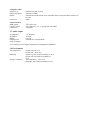
Electron Service Manual
Part no 0405001
Issue no 2
Date January 1987
© Copyright Acorn Computers Limited 1984
Neither the whole or any part of the information contained in, or the product described in, this manual may be adapted or reproduced
in any material form except with the prior written approval of Acorn Computers Limited (Acorn Computers).
The product described in this manual and products for use with it are subject to continuous development and improvement. All
information of a technical nature and particulars of the product and its use (including the information and particulars in this manual)
are given by Acorn Computers in good faith. However, it is acknowledged that there may be errors or omissions in this manual. A list
of details of any amendments or revisions to this manual can be obtained upon request from Acorn Computers Technical Enquiries.
Acorn Computers welcome comments and suggestions relating to the product and this manual.
All correspondence should be addressed to:
Technical Enquiries
Acorn Computers Limited
Fulbourn Road
Cherry Hinton
Cambridge CB1 4JN
All maintenance and service on the product must be carried out by Acorn Computers' authorised dealers. Acorn Computers can
accept no liability whatsoever for any loss or damage caused by service or maintenance by unauthorised personnel. This manual is
intended only to assist the reader in the use of the product, and therefore Acorn Computers shall not be liable for any loss or damage
whatsoever arising from the use of any information or particulars in, or any error or omission in, this manual, or any incorrect use of
the product.
This manual is for the sole use of Acorn Computers' authorised dealers and must only be used by them in connection with the product
described within. This manual remains the property of Acorn Computers at all times and must be returned to them immediately upon
the termination of the dealer's appointment.
First published 1984
Published by Acorn Computers Limited
Typeset by Bateman Typesetters, Cambridge
Contents
1 Introduction
1
2 Packaging and installation
2
3 Specification
3
3.1 Acorn Electron microcomputer
3.2 Machine operating system
3.3 BASIC
3.4 Power supply
3.5 Cassette interface
3.6 Video outputs
3.7 Audio output
3.8 Environment
3
3
4
4
4
4
4
5
5
5
5
4 Disassembly and assembly
6
5 Circuit description
7
5.1 General
5.2 PCB links
7
7
Modulated output
Composite video
Colour monitor
6 The uncommitted logic array (ULA)
7 Electron test equipment
8
9
8 Fault finding inside a dead Electron
10
8.1 Power supply
8.2 Oscillator
8.3 ULA
8.4 CPU
8.5 ROM
8.6 DRAMs
8.7 Video
8.8 Cassette interface
8.9 Keyboard
8.10 Sound
10
10
10
11
11
11
11
13
14
14
Appendix
Diagnostic flowcharts
Final assembly
Electron block diagram
Functional block diagram of the Electron ULA
Main PCB circuit diagram
Main PCB layout
Main PCB silk-screen
Electron power supply board circuit diagram
Keyboard matrix
Electron parts lists
15
25
27
29
31
33
35
37
39
41
1 Introduction
This manual is intended to provide the information required to diagnose and repair faults on the Electron microcomputer
which was designed by Acorn Computers Limited of Cambridge, England.
The information contained in this manual is aimed at service engineers and Acorn dealers who will be servicing the Electron
microcomputer on behalf of Acorn Computers Limited.
2 Packaging and installation
The Electron microcomputer is supplied in a two-part moulded polystyrene packing which is further packaged within a
cardboard sleeve. Supplied with the microcomputer is a User Guide, a book called Start Programming with the Electron,
an Introductory Cassette package, a UHF TV lead, and a mains power adapter.
The mains supply for UK models is 240V AC 50Hz. Power is delivered to the microcomputer from a separate mains power
adapter which has a built-in square pin plug. This plug cannot be changed, and if it is unsuitable for the socket outlet available
then an adapter must be used.
The output from the mains power adapter is 19V AC 50Hz at 14 watts.
The lead on the mains power adapter plugs into the microcomputer in a socket on the right side. This socket is labelled 19V.A.
C. POWER IN on the bottom of the machine.
Do not use the microcomputer in conditions of extreme heat, cold, humidity or dust or in places subject to vibration. Do not
block ventilation under or behind the computer. Ensure that no foreign objects are inserted through any openings in the
microcomputer.
2
3 Specification
3.1 Acorn Electron microcomputer
A fast, powerful, self-contained computer system generating high resolution colour graphics and capable
of synthesising music or noise. The computer is contained in a rigid injection moulded thermoplastic case.
The computer provides the following facilities.
A 56-key full travel QWERTY keyboard with ten user definable function keys, two-key rollover, and autorepeat.
The internal loudspeaker is driven from a music synthesis circuit with envelope control.
A modulated 625-line PAL A UHF colour television signal (channel E36) for connection to a normal
domestic television aerial socket is available through a phono connector.
A 6-pin DIN RGB connector supplies output for use with a colour monitor.
A phono connector supplies a video output to drive a black and white monitor.
A standard audio cassette recorder can be used to record computer programs and data files at 1200 baud
using the CUTS standard tones. The cassette recorder is under automatic motor control and is connected
to the computer via a 7-pin DIN connector.
An interrupt driven elapsed time clock enables real time control and timing of user responses.
The unit uses a 2MHz 6502 and includes 32K of read/write Random Access Memory.
A 32K Read Only Memory (ROM) integrated circuit contains an extensive and powerful machine
operating system, and an extremely powerful and fast BASIC interpreter. The interpreter includes a 6502
assembler which enables BASIC statements to be freely mixed with 6502 assembly language.
The standard television output is 625-line 50Hz, interlaced, fully encoded PAL, modulated on UHF
channel 36.
The display modes provide user definable characters in addition to the standard upper and lower case
alphanumeric font. Graphics may be freely mixed with text. Text characters can be positioned not only on,
for example, a 40 X 32 grid, but at any intermediate position in graphics modes.
Separate or overlapping text and graphics windows can be easily user defined over any area of the display.
Each of these windows may be filled and scrolled separately.
The Electron is able to support the following modes:
0 640 X 256 two-colour graphics and 80 X 32 text (20K)
1 320 X 256 four-colour graphics and 40 X 32 text (20K)
2 160 X 256 sixteen-colour graphics and 20 X 32 text (20K)
3 80 X 25 two-colour text (16K)
4 320 X 256 two-colour graphics and 40 X 32 text (10K)
5 160 X 256 four-colour graphics and 20 X 32 text (10K)
6 40 X 25 two-colour text (8K)
The installed RAM is divided between the high resolution graphics display, the user's program, and
machine operating system variables. The MOS requires 3.5K of RAM.
3.2 Machine operating system
A 32K byte ROM is used for both the MOS and the BASIC interpreter. The MOS software controls all
input/output devices using a well defined interface. The MOS supports the following interrupts:
– Event timer (used as elapsed time clock).
– Vertical sync.
3
– Keyboard and keyboard buffer.
– Serial interface, input and output, and buffers.
Many of the operating system calls are vectored to enable the user to change them if required.
3.3 BASIC
The BASIC interpreter is a fast implementation, very close to Microsoft standard but with numerous powerful extensions:
–
–
–
–
Long variable names.
Integer, floating point and string variables.
Multi-dimension integer, floating point and string arrays.
Extensive support for string handling.
—
—
–
–
–
–
–
–
–
–
–
IF...THEN...ELSE.
REPEAT...UNTIL.
Multi-line integer, floating point and string functions.
Procedures.
Local variables.
Full recursion on all functions and procedures.
Effective error trapping and handling.
Cassette loading and saving of programs and data.
Full support for the extensive colour graphics facilities.
Easy control of the built-in music generation circuits.
Built-in 6502 mnemonic assembler enabling BASIC and assembler to be mixed, or pure assembly language programs to be
produced.
3.4 Power supply
Transformer:
Maximum AC input
Minimum AC input
Rating
Supply frequency
264V AC
216V AC
14 watts
47 to 63Hz
Power supply module:
Maximum AC input
Minimum AC input
Maximum current
20.9V RMS
17.1V RMS
+5V rail – 1.5A
–5V rail – 100mA
3.5 Cassette interface
Output impedance
Input impedance
Output level
Dynamic input range
Motor control
Baud rate
Connector
Less than 1k ohms
Greater than 100k ohms
Nominal 200mV peak to peak, 70mV RMS
Nominal 50mV to 5V peak to peak, –25 to +15dB, 0dB 350mV RMS
By miniature relay within computer
Contact rating 1A at 24V DC
1200 baud using standard CUTS tones
7-pin DIN socket
3.6 Video outputs
Modulated output
Standard
Channel
Vision carrier
RF output
6db bandwidth
RF output impedance
Connector
4
625-line PAL A UHF colour television signal
E36
Nominal 591.25MHz
1.0 to 2.5mV
15 to 20MHz
75 ohms
Phono
Composite video
Output level
Output impedance
Option
Connector
Nominal 1V peak to peak
Nominal 75 ohms
Chrominance information (wire selectable) allows composite PAL monitors to
be used
Phono
Colour monitor
RGB signals
CSYNC signal
Connector
TTL type levels
TTL type level +ve/–ve going (link selectable)
6-pin DIN
3.7 Audio output
Loudspeaker
1.5" diameter
Impedance
16 ohms
Rating
0.2 watt
Output power
Nominal 0.1 watt maximum
(from computer)
Note: Sound circuit is largely independent of loudspeaker impedance.
3.8 Environment
Air temperature
Humidity
Storage conditions
System on: 0 to 35°C
System off: –20 to 70°C
System on: 85% relative humidity at 35°C
System off: 95% relative humidity at
55°C
Air temperature: –20 to 70°C
Humidity: 95% relative humidity at 55°C
5
4 Disassembly and assembly
To service the Electron, disconnect the power supply lead and undo the four fixing screws underneath, two recessed in the
front corners and two in the cutaway portion on the back edge. (The assembly diagram is given in the Appendix.) When you
split the computer the keyboard is attached to one half and the two PCBs are in the other. These two halves are connected to
each other by a short piece of ribbon cable. The ribbon cable is attached to the main PCB by a socket, which should be
unplugged before carrying out repairs. (Note however that the Electron will not run without the keyboard connected.)
The keyboard can be removed from the top case by undoing the five philips screws which hold it in place.
The bottom case contains two PCBs, the smaller one being the power supply board. This is connected to the main PCB by a
socket and two 'faston' tabs which are marked 18V AC and lead only to the expansion port. The socket connects three wires to
the main PCB: red +5V, blue —5V, black ground. The loudspeaker is also connected to the main PCB via a socket. All of
these sockets and wires may be unplugged to allow removal of the PCBs from the bottom case.
The main PCB is held in place by four philips screws, the power supply PCB by three.
6
5 Circuit description
5.1 General
The microprocessor used in the Electron is a 6502A with the clock signals provided by a 16MHz crystal oscillator (IC8) in
conjunction with divider circuitry in the ULA (IC1). The 6502 runs at three speeds depending on what is being accessed:
2MHz: The processor will run at 2MHz during an access cycle to the ROM. This is because the ROM is being accessed only
by the processor which has a maximum speed of 2MHz.
1MHz: The processor will run at 1MHz during an access cycle to the RAM. The processor and the video are competing for
access to the RAM, and the RAM can only support a bandwidth of 2MHz. In screen modes 4, 5 and 6 this is no problem since
the screen only needs 1MHz access to the RAM.
Stopped: In screen modes 0, 1, 2 and 3 the screen uses all the available memory time slots during the display period. The
processor is denied RAM access during 40 microseconds of each 64 microseconds of the 256 lines in 312 which is the display
period, and it is made to wait for RAM access until the end of the period.
Random Access (read/write) Memory on the Electron is provided by four 64Kbit dynamic memory devices (ICs 4 to 7), giving
32Kbytes in all. This means that to read a byte from memory requires two accesses. IC4 contains bit 0 and bit 1, IC5 contains
bit 2 and bit 3, IC6 contains bit 4 and bit 5, and IC7 contains bit 6 and bit 7. The mechanism for doing this is handled by the
ULA.
The timing diagram for the DRAMs is shown below.
5.2 PCB links
There are several links on the Electron PCB, most of which are hard-wired in the correct position. The action of these links can
be ascertained from the circuit diagram (see Appendix), but two are of special interest:
LK3 controls the action of CSYNC. LK3 is set to ground as standard, and setting LK3 to +5V causes CSYNC to be inverted.
The correct setting will depend on the type of RGB monitor in use.
LK4 is normally open circuit. If it is made it adds the chrominance component to the composite video output. This is useful
when debugging the video circuitry (see chapter 8) and also, of course, when using a colour composite monitor.
7
6 The uncommitted logic array
(ULA)
The ULA (IC 1) coordinates every function of the computer. It is contained in a quad in-line package, pin 1 being
marked at the top left of the chip, and the other pins following consecutively anti-clockwise around the package. (
For the method of removal of ULA from its holder see 8.3.) It has 68 pins in all. Each pin, as labelled on the
circuit diagram (see Appendix), functions as follows:
CAS OUT: Pseudo sinusoidal output to cassette circuitry. 1.8V peak to peak:
CAS RC: This is an input/output connected to an RC circuit. The RC is used to detect a continuous period of high
tone on the cassette input.
CAS MO: This output drives the transistor which operates the tape motor relay:
CAS IN: This is the input from the cassette circuitry which goes to the ULA cassette deserialiser. The input
voltage should be between 0.5V and 2V peak to peak.
SOUND 0/P• Delivers a tone to the speaker from an internal oscillator.
POR (power on reset): On power up, the RC circuit connected to this input provides a +ve edge to reset parts of
the ULA, and to cause the ULA to activate the RST line which resets the processor.
CSYNC: This output is part of the CRT control circuitry and is low during either a horizontal synchronisation
period or during a vertical synchronisation period, and is high at all other times.
RED, GREEN, BLUE: These TTL outputs are active high and give the current pixel colour.
HS: This output is part of the CRT control circuitry and is low during a horizontal synchronisation period and
high at all other times:
CLOCK IN: 16MHz clock input.
÷13 IN: Divided by 13 clock input.
RAMO . : : RAMS: Data lines to and from the RAM. Data flow is controlled by RAS, CAS and WE.
WE: The write enable line at logic 0 selects a write operation to the RAM and at logic 1 selects a read operation
from the RAM.
RAS: The row address strobe latches the row address into the RAM on a —ve edge and also controls refresh.
CAS: The column address strobe latches the column address into the RAM on a —ve edge. RAO : : : RA7: RAM
address lines which send both row and column addresses to the RAM: KBDO : : : KBD3: Direct inputs from the
keyboard.
CAPS LOCK: Output which controls the CAPS LOCK LED.
RST: Master reset for the 6502: Enabled on power up and when the
ROM select output which enables data to be read from the ROM.
BREAK
key is pressed. ROM:
AO : : : A15: Processor address lines which take memory address information from the 6502.
PDO : : : PD7: Processor data lines which send data to and receive data from the 6502:
NMI: The ULA is responsible for all RAM accesses and uses the NMI input to determine whether the processor
should have full 1MHz access to the RAM regardless of screen mode.
PHI OUT: This output provides the processor with its clock. The processor works at one of three speeds: 2MHz,
1MHz and stopped. It is derived from the 16MHz input.
IRQ: This output is used by the ULA to interrupt the processor when certain events within the ULA have
occurred:
R/W: This is an input through which the processor tells the ULA the direction of data on the data bus, logic 0 for
processor write and logic 1 for processor read:
(A functional block diagram of the ULA is given in the Appendix.)
8
7 Electron test equipment
Two test systems are available for the Electron, and can be purchased from Acorn Computers Limited: The 'PIT test' (
production inspection test) can sometimes identify the area of the Electron in which the problem lies.
The 'Electron Watchdog' is a soak testing device which is used to show up intermittent faults: Full operating
instructions are supplied with the equipment:
9
8 Fault finding inside a dead
Electron
This chapter will take you step by step through fault diagnosis inside the Electron, assuming that any part of the machine could
be faulty. If you know roughly the area in which you believe a fault lies then you can go straight to that part of the analysis.
This chapter should be studied in conjunction with the circuit diagram and block diagram of the machine and flowcharts which
are given in the Appendix. Obviously with some machines fault diagnosis will not be possible.
8.1 Power supply
Using an AC voltmeter, measure the output from the mains power adapter when it is plugged into a working Electron. (The
measurement can be made most easily across the two grey leads where they connect to the power supply PCB.) The voltage
should be at least 17V RMS. If not then replace the mains power adapter.
Next, remove the power supply connector from the right side of the Electron's main PCB. Connect a 10 ohm 2.5W resistor
across the red and black leads (the +5V supply) and measure the voltage using an oscilloscope (all measurements on the power
supply should be made with a resistive load drawing around 500mA from the +5V side). The voltage should be between +4:75
and +5.25 volts, and a maximum of 50mV noise is permissible.
If the mains power adapter works but the 5V supply is dead or the voltage is out of spec then replace the power supply PCB
and test again. The power supply PCB is easy to work on and can be repaired if you wish (see circuit diagram).
If the +5V voltage is correct then adjust the zero volts trace to the middle of the screen on the oscilloscope and test the —5V
supply across the blue and black leads (the trace should deflect in the opposite direction): The —5V supply should be tested
with a 47 ohm resistive load (and keep the 10 ohm load across the +5V red and black leads): Any fault on the —5V line will
show up as a cassette fault:
Now remove both resistors and test the current drawn by the main PCB from the +5V supply. The board should draw 700-900
mA from the +5V supply. If the +5V current is zero then at the same time measure the voltage: If the voltage is 5V then the
main PCB has gone open circuit so look at the connectors and tracks. If the voltage is 0V then the power supply has cut out
due to overload and there is a short circuit on the main PCB. The power supply is short circuit protected, and the power supply
lead must be removed from the Electron for at least 15 seconds for the power supply supply board to reset.
If the current from the +5V is higher than it should be then measure the voltage. If the voltage is greater than 5.25V then
replace the power supply PCB: If the voltage is in spec (4:75 to 5.25V) then one or more of the ICs or other components on the
main PCB is short circuiting. Disconnect the power supply and feel which of the components is abnormally hot.
The +5V supply rails are laid out in a ring around the board, and so would have to break in two places for any section to be
isolated.
Now measure the —5V current which should be approximately 25mA. If the —5V current is zero then either there is a short
circuit, or the LM324 is disconnected because of a broken track.
8.2 Oscillator
Check with the oscilloscope that a 16MHz 4V peak to peak clock pulse is reaching the ULA (pin 49 of IC 1). If this signal is
good then the oscillator is working: If not, check pin 8 of IC8; there could be a track broken between the two. Next check that
there is 5V across pin 14 (+ve) and pin 7 (ground) of IC8. If the oscillator is not working then it could be the 74S04 (IC8), the
crystal, or any of the passive components around them.
8.3 ULA
The ULA is tested before being installed in the Electron. As it is easily removed, the best way to check it is to use the machine
with a known good one (a good ULA must always be kept for Electron fault diagnosis): The method of removal and insertion
is as follows.
10
The ULA is IC 1 on the PCB, and is held in place by a square metal clip. To remove the ULA, insert a small
screwdriver between the front left corner of the clip and the plastic ULA holder as shown in the diagram below,
being extremely careful not to let it touch the PCB tracks (which are very easily damaged).
Figure 2
Twist the screwdriver until that corner unclips and then repeat the procedure for the front right corner. The clip
should then spring off altogether and the ULA can be removed by turning the Electron upside down.
Insert the good ULA, making sure that the notches cut out of the three corners are in the correct position inside
the carrier, and that the little metal spring in the remaining corner is not bent down under the ULA. When the
ULA is seated correctly, replace the clip by pressing it on to the socket with the fingers:
Check the power supply (pins 9, 43, 48 +5V; pins 51, 68, ground; see circuit diagram).
Check that the clock output is present on pin 60. In modes 4, 5 and 6 this will be varying between 1MHz and
2MHz: In modes 0, 1, 2 and 3 there is no clock output at all for some of the time (see chapter 5).
Check that the ROM line (pin 61) is wobbling (is not fixed at one logic level). Do this also for the two RAM
address strobes RAS and CAS (pin 52 and pin 53). If RAS is fixed at logic 0 then the DRAMs are very rapidly
destroyed.
For a description of ULA function see chapter 6.
8.4 CPU
Check the power supply to IC3 (pins 1 and 21 ground, pin 8 +5V). Test the clock input (pin 37) which should be
varying between 1MHz and 2MHz in modes 4, 5 and 6, and also stopped for some of the time in modes 0, 1, 2 and
3 (see chapter 5): Check that the IRQ (pin 4), NMI (pin 6), and R/W (pin 34) lines are wobbling (are not fixed at
one logic level). If these lines are fixed then test the reset line (pin 40) which should be +5V. If it is held low then
there could be a short on the PCB or the ULA could be faulty. Press BREAK while monitoring the reset and check
that it goes to 0V.
8.5 ROM
Check the power supply to IC2 (pin 28 +5V, pin 14 ground). Check that the output enable (pin 22) is wobbling (is
not fixed at one logic level), and also the address lines.
8.6 DRAMs
Check the power supply on pin 8 (+5V) and pin 16 (ground) of ICs 4, 5, 6 and 7: Check that the row and column
address strobes RAS (pin 4) and CAS (pin 15) are wobbling (see figure 1 in section 5.1): If they are not then the
DRAMs may be destroyed, and there is a track broken (assuming RAS and CAS are present at the ULA).
8.7 Video
Look at the displays from the three monitors (RGB, UHF and composite) and see which of the following, (a), (b),
(c) or (d), best describes them.
a) If none of the monitors operates (RGB, UHF and composite) then there is no signal coming from the ULA.
Replace the ULA and test again:
11
b) If the RGB works but the UHF doesn't then test the UHF modulator input voltage waveform using the oscilloscope. Set the
oscilloscope to 50mV per division, 10 microseconds per division, auto trigger, and attach the probe to the wire shown in the
diagram.
Press BREAK on the computer and check that the PAL waveform looks something like this:
Type in the following:
COLOUR129: CLS
and press RETURN .
12
The waveform should now look like this:
If these waveforms are correct and the UHF monitor does not give a display then the PAL modulator is faulty and
should be replaced.
If the colour burst part of the waveforms is missing then the fault lies in the chrominance circuitry (see below).
If any other part of the waveforms is incorrect, make link 4 temporarily (with a pair of pliers perhaps) and test the
composite video output with the oscilloscope. The waveforms should be similar to those indicated above, but of
reduced amplitude (1V peak to peak).
If the composite output waveforms are good with link 4 made (including colour burst), but the UHF output does
not work, then the fault lies in the UHF luminance circuitry (Q5, D1, D2, D3, C13 and associated resistors).
Check that diodes D1, D2 and D3 are inserted the correct way round (the PCB is marked +).
If the video output waveforms are bad then the video luminance circuitry (Q8 and associated resistors) is faulty,
and possibly chrominance circuitry also (see below).
A composite colour monitor can be used to test the video output with link 4 made. If the composite colour
monitor works in black and white only then the chrominance circuitry is faulty (see below).
c) If the RGB works and the UHF works in black and white only then the chrominance circuitry is faulty.
Test pin 6 of IC8 with a frequency counter. The measured frequency must be 17.7345MHz ± 200Hz, and can be
adjusted using VC1. If there is no signal on pin 6 then debug as for the oscillator in section 8.2.
Check that the 17.7345MHz is reaching pins 3 and 11 of IC 11. IC11 is a 74S74. A 74LS74 inserted in this
position can cause the circuit to fail. Check that there are signals from pins 9 and 6 of IC 11 (4.4336MHz), and
also signals from pins 5 (7.7kHz approx) and 9 of IC 12.
Check that L1 has not gone open circuit and that C21 has not short circuited, and check Q7. Failing all
this, test the logic circuit formed by IC 14, IC 15, IC 16, IC10 and resistors R50 to R57.
d) If the RGB picture is distorted and out of synchronisation then LK3 must be altered to invert CSYNC. LK3
must be set to suit whichever RGB monitor is being used with the computer.
8.8 Cassette interface
First test that the 16MHz clock is arriving at pin 2 of IC9.
Then test that the divided by 13 clock (812ns period) is leaving pin 11 of IC9 and is arriving at pin 55 of the ULA
(IC 1). If it is not then IC9 is not working. Check the power supply to IC9, pin 16 +5V, pin 8 ground.
Check the fixed voltage connections to the LM324 (IC 13), pin 4 +5V, pin 11 –5V.
To test the cassette output, if the Electron will accept commands then SAVE a program or section of memory (
from the ROM is best) and check that there is a synthesised sine-wave signal from pin 50 of the ULA of around 1.
8V peak to peak.
13
To test the cassette input, press BREAK and measure the quiescent voltage of each of the three amplifier outputs,
pin 7, pin 8 and pin 14 of IC 13. This voltage should not be greater than 100mV. If any of these pins is at too high
a voltage then replace the LM324. To test the input, L 0 A D a program from a cassette which is known to work
and check that a signal is arriving at pin 59 of the ULA with an amplitude of between 500mV and 2V.
8.9 Keyboard
The PIT system will test the keyboard. A manual check is possible using an ohm meter and the keyboard circuit
diagram. Check for shorts, dry joints and lifted tracks. Replace any faulty keys. Check that both ends of the
keyboard connector cable are making good contact, that the connector on the Electron end of the cable is covering
all the pins (it could be inserted with an offset and miss some of the pins), and that the cable is not damaged in any
way. Check that the diodes and resistors are correctly fitted and are of the correct value.
8.10 Sound
If the Electron will accept commands then give a SOUND command and check that there is a signal from pin 62 of
the ULA (IC1): If not then replace the ULA with a known good one and try again. Check all the connections in
the simple amplifier circuit to the loudspeaker, especially transistors Q3 and Q4 (see circuit diagram).
14
Appendix
Diagnostic flowcharts
8.1 Power supply
15
8.2 Oscillator
16
23
8.4 CPU
18
8.5 ROM
19
8.6 DRAMs
20
8.7 Video
21
8.8 Cassette interface
22
8.10 Sound
23
Final assembly
Electron block diagram
Functional block diagram of the Electron ULA
Main PCB circuit diagram
Main PCB layout
Main PCB silk-screen
Electron power supply board circuit diagram
Keyboard matrix
Electron parts lists
Electron keyboard assembly
Item
Part No
Description
Qty
1
2
3
4
5
6
7
8
9
10
11
12
13
14
15
16
17
18
19
20
21
22
23
24
25
26
27
28
29
30
205,002
201,089
105,002
201,079
Bare PCB
Keyboard support plate
Assembly drawing
Keytop set
1
1
Remarks
500,471
500,153
Resistor 470R 1/4W 10% carbon
Resistor 15K 1/4W 10% carbon
1
4
R1
R2-5
651,474
Capacitor 0.47µF disc ceramic
1
Cl
794,148
799,001
880,040
886,003
Diode IN4148
LED TIL212-2
Sleeve 10mm long
Keyboard switch
14
1
2
56
D1-14
LD1
882,972
882,121
Washer M3 shakeproof
Screw M3 X 6mm pan head posidrive
2
2
870,222
Ribbon cable assembly
1
886,000
886,001
886,002
Space Bar wire
Wire holder
Push rod
1
2
2
890,010
RTV silicon compound
A/R
1 per batch
1
Electron final assembly
Item
1
2
3
4
5
6
7
8
9
10
11
12
13
14
15
16
17
Part No
Description
Qty
005,000/A Final assembly drawing
005,000/PG Packaging assembly
105,000
Main PCB assembly
105,002
Keyboard assembly
1
1
201,080
201,081
201,112
332,002
Case top moulding
Case base moulding
Case label
PSU/PCB assembly
1
1
1
1
890,010
201,123
201,203
883,306
882,673
RTV silicon compound
Self-adhesive foam pad
Speaker
Screw M3 X 6
Screw No 4 X 5/16" flange head posidrive
A/R
1
1
12
4
Remarks
1 per works order
1 per works order
41
18
19
20
21
22
23
24
25
26
27
28
29
30
890,001
201,248
Rubber foot
4
Expansion connector cover
1
201,308
Registration label
1
Electron main PCB
Item
1
2
3
4
5
6
7
8
9
10
11
12
13
14
15
16
17
18
19
20
21
22
23
24
25
26
27
28
29
30
31
32
33
34
35
36
37
38
39
42
Part No
Description
Qty
205,000
105,000
502,100
508,240
502,470
502,680
502,101
502,471
502,681
502,821
502,102
Bare PCB
Assembly drawing
Resistor 10R ¼W 5% carbon
Resistor 24R ¼W 10% carbon
Resistor 47R ¼W 5% carbon
Resistor 68R ¼W 5% carbon
Resistor 100R ¼W 5% carbon
Resistor 470R ¼W 5% carbon
Resistor 680R W 5% carbon
Resistor 820R W 5% carbon
Resistor 1K ¼W 5% carbon
1
Remarks
2
2
1
6
1
4
2
5
7
1 per batch
R65,66
R5,58
R61
R21,45,46,47,48,49
R17
R13,38,40,53
R51,56,57
R1,2,3,4,50
R16,22,32,34,37, 39,
63
502,122
502,152
502,222
502,182
502,332
502,392
502,472
502,562
502,822
Resistor 1K2R ¼W 5% carbon
Resistor 1K5R W 5% carbon
Resistor 2K2R W 5% carbon
Resistor 1K8 1%W 5% carbon
Resistor 3K3R W 5% carbon
Resistor 3K9R W 5% carbon
Resistor 4K7R W 5% carbon
Resistor 5K6R ¼W 5% carbon
Resistor 8K2R W 5% carbon
2
1
4
1
3
3
2
1
2
R54,41
R19
R12,24,33,52
R26
R8,55,71
R14,31,42
R10,11
R15
R25,27
502,103
502,393
502,563
502,104
502,124
502,154
502,224
502,274
502,824
Resistor 10K ¼W 5% carbon
Resistor 39K W 5% carbon
Resistor 56K W 5% carbon
Resistor 100K ¼W 5% carbon
Resistor 120K ¼W 5% carbon
Resistor 150K ¼W 5% carbon
Resistor 220K W 5% carbon
Resistor 270K ¼W 5% carbon
Resistor 820K ¼W carbon
3
1
2
1
2
2
1
1
1
R18,28,64
R20
R6,7
R23
R29,30
R35,44
R36
R9
R43
685,330
631,039
Capacitor 33p plate ceramic
Capacitor 39p plate ceramic
2
1
C4,6
C18
685,470
685,101
Capacitor 47p plate ceramic
Capacitor 100p plate ceramic
1
2
C21
C3,5
40
41
42
43
44
45
46
47
48
49
50
51
52
53
54
55
56
57
58
59
60
61
62
63
64
65
66
67
68
69
70
71
72
73
74
75
76
77
78
79
80
81
82
83
84
85
86
87
88
89
90
91
92
93
94
95
96
97
685,151
685,471
633,082
630,150
629,002
634,004
680,001
685,333
651,224
Capacitor 150p plate ceramic
Capacitor 470p plate ceramic
Capacitor 820p plate ceramic
Capacitor 1n5 plate ceramic
Capacitor 2n2 plate ceramic
Capacitor 4n7 plate ceramic
Capacitor 47n/33n decoupler
Capacitor 33n ceramic multilayer
Capacitor 220n ceramic disc
1
1
2
1
1
2
18
1
2
C13
C17
C20,22
C26
C15
C14,16
A
C12
C10,19
613,100
622,330
624,100
622,100
622,470
699,004
611,470
794,148
Capacitor lu 35V tantalum
Capacitor 33u 16V electrolytic axial
Capacitor 10u 35V electrolytic axial
Capacitor 10u 16V electrolytic axial
Capacitor 47u 16V electrolytic
Capacitor variable 5.5-40p
Capacitor 47u 16V Tantalum
Diode IN4148
2
1
2
1
1
1
1
7
C8,9
C25
C11,7
C2
C1
VC 1
C23
D1-7
780,183
780,213
780,239
780,309
Transistor BC 183L
Transistor BC 213L
Transistor BC239
Transistor BC309
1
1
4
2
Q3
Q4
Q1,2,6,7
Q5,8
741,004
741,074
742,000
742,074
742,086
743,169
Integrated circuit 74S04
Integrated circuit 74S74
Integrated circuit 74LS00
Integrated circuit 74LS74
Integrated circuit 74LS86
Integrated circuit 74LS169A
1
1
2
1
2
1
IC8
IC11
IC10,16
IC12
IC14,15
IC9
770,324
704,864
706,502
201,620
201,621
800,852
800,094
Integrated circuit LM324
Integrated circuit 4164
Integrated circuit 6502A
Integrated crcuit 12CO21
Integrated circuit OS/BASIC
3-way 0.156" SIL lock right angle
3-way 0.1" SIL right angle
1
4
1
1
1
1
1
IC13
IC4,5,6,7
IC3
IC1
IC2
PL3
LK3
800,050
2-way SIL pin
1
SPKR
800,070
800,002
800,003
Shunt
6-pin DIN socket
7-pin DIN socket
1
1
1
LK3(E)
SK2
SK1
800,611
800,200
Video connector
Faston tab
1
2
800,168
IC socket 68-way
1
IC1
810,001
860,005
Relay
Coil 33uH
1
1
RL1
L1
820,177
Crystal 17.7345MHz
1
X2
SK3
18 VACIN,
RETURN
43
98
99
100
101
102
103
104
105
106
107
108
109
110
44
820,160
Crystal 16MHz
1
X1
880,040
825,000
Sleeving
UHF modulator UM1233-E36
A/R
1
Use with item 102
SK4
NOTES
NOTES