1
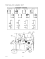
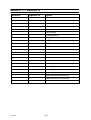
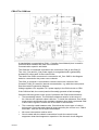
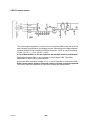
Mig 4002cw, Mig 4002c Mig 5002cw, Mig 5002c Mig 6502cw, Mig 6502c Origo Service manual 0349 300 080 101229 Valid for serial no. 740,743,741,744,742,745,801,802,803,804,806,805--xxx--xxxx READ THIS FIRST . . . . . . . . . . . . . . . . . . . . . . . . . . . . . . . . . . . . . . . . . . . . . . . . . . . . . . . . . . . . . . . . . INTRODUCTION . . . . . . . . . . . . . . . . . . . . . . . . . . . . . . . . . . . . . . . . . . . . . . . . . . . . . . . . . . . . . . . . . . . TECHNICAL DATA . . . . . . . . . . . . . . . . . . . . . . . . . . . . . . . . . . . . . . . . . . . . . . . . . . . . . . . . . . . . . . . . . WIRING DIAGRAM . . . . . . . . . . . . . . . . . . . . . . . . . . . . . . . . . . . . . . . . . . . . . . . . . . . . . . . . . . . . . . . . . Component description . . . . . . . . . . . . . . . . . . . . . . . . . . . . . . . . . . . . . . . . . . . . . . . . . . . . . . . . . . OrigoTM Mig 4002c / 5002c / 6502c block diagram . . . . . . . . . . . . . . . . . . . . . . . . . . . . . . . . . ? 230V / 400--415V / 440--460V / 500V ? . . . . . . . . . . . . . . . . . . . . . . . . . . . . . . . . . . . . . . . . . . . . Burndy 23 <--> Amphenol 19 . . . . . . . . . . . . . . . . . . . . . . . . . . . . . . . . . . . . . . . . . . . . . . . . . . . . DESCRIPTION OF OPERATION . . . . . . . . . . . . . . . . . . . . . . . . . . . . . . . . . . . . . . . . . . . . . . . . . . . . . CB0 Control circuit board . . . . . . . . . . . . . . . . . . . . . . . . . . . . . . . . . . . . . . . . . . . . . . . . . . . . . . . . CB0:1 Circuit board identity . . . . . . . . . . . . . . . . . . . . . . . . . . . . . . . . . . . . . . . . . . . . . . . . . . . . . . . . CB0:2 Power supply . . . . . . . . . . . . . . . . . . . . . . . . . . . . . . . . . . . . . . . . . . . . . . . . . . . . . . . . . . . . . . CB0:3 The CAN bus . . . . . . . . . . . . . . . . . . . . . . . . . . . . . . . . . . . . . . . . . . . . . . . . . . . . . . . . . . . . . . Terminating resistors . . . . . . . . . . . . . . . . . . . . . . . . . . . . . . . . . . . . . . . . . . . . . . . . . . . . . . . . . . . . . . CB0:4 Temperature monitoring . . . . . . . . . . . . . . . . . . . . . . . . . . . . . . . . . . . . . . . . . . . . . . . . . . . . . CB0:5 Current sensor . . . . . . . . . . . . . . . . . . . . . . . . . . . . . . . . . . . . . . . . . . . . . . . . . . . . . . . . . . . . . CB0:5.1 Calibrating the current sensor signal . . . . . . . . . . . . . . . . . . . . . . . . . . . . . . . . . . . . . . . . . CB0:6 Arc voltage input Mig/Mag . . . . . . . . . . . . . . . . . . . . . . . . . . . . . . . . . . . . . . . . . . . . . . . . . . . CB0:6.1 Calibration of the arc voltage feedback . . . . . . . . . . . . . . . . . . . . . . . . . . . . . . . . . . . . . . CB0:7 Arc voltage input in MMA process . . . . . . . . . . . . . . . . . . . . . . . . . . . . . . . . . . . . . . . . . . . . CB0 Components positions . . . . . . . . . . . . . . . . . . . . . . . . . . . . . . . . . . . . . . . . . . . . . . . . . . . . . . . . ACH10 Driver/relays board . . . . . . . . . . . . . . . . . . . . . . . . . . . . . . . . . . . . . . . . . . . . . . . . . . . . . . . ACH10:1 Circuit diagram . . . . . . . . . . . . . . . . . . . . . . . . . . . . . . . . . . . . . . . . . . . . . . . . . . . . . . . . . . ACH10:2 Power supply . . . . . . . . . . . . . . . . . . . . . . . . . . . . . . . . . . . . . . . . . . . . . . . . . . . . . . . . . . . . ACH10:3 PWM driver . . . . . . . . . . . . . . . . . . . . . . . . . . . . . . . . . . . . . . . . . . . . . . . . . . . . . . . . . . . . . ACH10:4 Pre charging voltage sense . . . . . . . . . . . . . . . . . . . . . . . . . . . . . . . . . . . . . . . . . . . . . . . ACH10:5 Mains contactor circuit, energy saving . . . . . . . . . . . . . . . . . . . . . . . . . . . . . . . . . . . . . . ACH10:6 Cooling fan . . . . . . . . . . . . . . . . . . . . . . . . . . . . . . . . . . . . . . . . . . . . . . . . . . . . . . . . . . . . . ACH10:7 Cooling liquid pump . . . . . . . . . . . . . . . . . . . . . . . . . . . . . . . . . . . . . . . . . . . . . . . . . . . . . . ACH10:8 Flow guard . . . . . . . . . . . . . . . . . . . . . . . . . . . . . . . . . . . . . . . . . . . . . . . . . . . . . . . . . . . . . . ACH10 Components positions . . . . . . . . . . . . . . . . . . . . . . . . . . . . . . . . . . . . . . . . . . . . . . . . . . . . . PF20 Suppression circuit board . . . . . . . . . . . . . . . . . . . . . . . . . . . . . . . . . . . . . . . . . . . . . . . . . . PF20:1 Circuit diagram . . . . . . . . . . . . . . . . . . . . . . . . . . . . . . . . . . . . . . . . . . . . . . . . . . . . . . . . . . . . PF20:2 Components positions . . . . . . . . . . . . . . . . . . . . . . . . . . . . . . . . . . . . . . . . . . . . . . . . . . . . . REMOTE CONTROLS . . . . . . . . . . . . . . . . . . . . . . . . . . . . . . . . . . . . . . . . . . . . . . . . . . . . . . . . . . . . . . FAULT CODES . . . . . . . . . . . . . . . . . . . . . . . . . . . . . . . . . . . . . . . . . . . . . . . . . . . . . . . . . . . . . . . . . . . . Fault log . . . . . . . . . . . . . . . . . . . . . . . . . . . . . . . . . . . . . . . . . . . . . . . . . . . . . . . . . . . . . . . . . . . . . . . . Fault code description, power source . . . . . . . . . . . . . . . . . . . . . . . . . . . . . . . . . . . . . . . . . . . . . . . . SERVICE INSTRUCTIONS . . . . . . . . . . . . . . . . . . . . . . . . . . . . . . . . . . . . . . . . . . . . . . . . . . . . . . . . . . What is ESD? . . . . . . . . . . . . . . . . . . . . . . . . . . . . . . . . . . . . . . . . . . . . . . . . . . . . . . . . . . . . . . . . . . . Service aid . . . . . . . . . . . . . . . . . . . . . . . . . . . . . . . . . . . . . . . . . . . . . . . . . . . . . . . . . . . . . . . . . . . . . . ESAB Administration Tool (ESAT) . . . . . . . . . . . . . . . . . . . . . . . . . . . . . . . . . . . . . . . . . . . . . . . . . . CAN supply service kit . . . . . . . . . . . . . . . . . . . . . . . . . . . . . . . . . . . . . . . . . . . . . . . . . . . . . . . . . . . . Antistatic service kit . . . . . . . . . . . . . . . . . . . . . . . . . . . . . . . . . . . . . . . . . . . . . . . . . . . . . . . . . . . . . . . Checking PWM signal . . . . . . . . . . . . . . . . . . . . . . . . . . . . . . . . . . . . . . . . . . . . . . . . . . . . . . . . . . . . . Checking thermal cutout . . . . . . . . . . . . . . . . . . . . . . . . . . . . . . . . . . . . . . . . . . . . . . . . . . . . . . . . . . . Checking Flow guard (only machines with Flow Guard sensor) . . . . . . . . . . . . . . . . . . . . . . . . . . . . . . . . . . . . . . . . . . . . . Checking pre charging circuit . . . . . . . . . . . . . . . . . . . . . . . . . . . . . . . . . . . . . . . . . . . . . . . . . . . . . . Checking Fan Circuit . . . . . . . . . . . . . . . . . . . . . . . . . . . . . . . . . . . . . . . . . . . . . . . . . . . . . . . . . . . . . . Checking liquid pump circuit . . . . . . . . . . . . . . . . . . . . . . . . . . . . . . . . . . . . . . . . . . . . . . . . . . . . . . . Checking the LED Indicators on board CB0 . . . . . . . . . . . . . . . . . . . . . . . . . . . . . . . . . . . . . . . . . . Checking chopper block V0 . . . . . . . . . . . . . . . . . . . . . . . . . . . . . . . . . . . . . . . . . . . . . . . . . . . . . . . . Overview test . . . . . . . . . . . . . . . . . . . . . . . . . . . . . . . . . . . . . . . . . . . . . . . . . . . . . . . . . . . . . . . . . . . . Rectifier test . . . . . . . . . . . . . . . . . . . . . . . . . . . . . . . . . . . . . . . . . . . . . . . . . . . . . . . . . . . . . . . . . . . . . Checking of output stage . . . . . . . . . . . . . . . . . . . . . . . . . . . . . . . . . . . . . . . . . . . . . . . . . . . . . . . . . . Replacing of damaged transistors . . . . . . . . . . . . . . . . . . . . . . . . . . . . . . . . . . . . . . . . . . . . . . . . . . High current aluminum leads maintenance . . . . . . . . . . . . . . . . . . . . . . . . . . . . . . . . . . . . . . . . TOCe -- 2 -- 4 4 5 8 8 9 18 19 20 20 20 20 21 22 22 23 24 25 26 28 29 30 30 30 31 32 33 33 34 34 35 36 36 36 36 37 37 38 41 41 42 42 42 43 43 46 47 48 48 49 50 51 53 53 54 55 55 INSTRUCTIONS . . . . . . . . . . . . . . . . . . . . . . . . . . . . . . . . . . . . . . . . . . . . . . . . . . . . . . . . . . . . . . . . . . . SAFETY . . . . . . . . . . . . . . . . . . . . . . . . . . . . . . . . . . . . . . . . . . . . . . . . . . . . . . . . . . . . . . . . . . . . . . . . . . INSTALLATION . . . . . . . . . . . . . . . . . . . . . . . . . . . . . . . . . . . . . . . . . . . . . . . . . . . . . . . . . . . . . . . . . . . . Placing . . . . . . . . . . . . . . . . . . . . . . . . . . . . . . . . . . . . . . . . . . . . . . . . . . . . . . . . . . . . . . . . . . . . . . . . . Assembly of components . . . . . . . . . . . . . . . . . . . . . . . . . . . . . . . . . . . . . . . . . . . . . . . . . . . . . . . . Mains power supply . . . . . . . . . . . . . . . . . . . . . . . . . . . . . . . . . . . . . . . . . . . . . . . . . . . . . . . . . . . . . OPERATION . . . . . . . . . . . . . . . . . . . . . . . . . . . . . . . . . . . . . . . . . . . . . . . . . . . . . . . . . . . . . . . . . . . . . . . Connections and control devices . . . . . . . . . . . . . . . . . . . . . . . . . . . . . . . . . . . . . . . . . . . . . . . . . Overheating protection . . . . . . . . . . . . . . . . . . . . . . . . . . . . . . . . . . . . . . . . . . . . . . . . . . . . . . . . . . Water connection . . . . . . . . . . . . . . . . . . . . . . . . . . . . . . . . . . . . . . . . . . . . . . . . . . . . . . . . . . . . . . . Water flow guard . . . . . . . . . . . . . . . . . . . . . . . . . . . . . . . . . . . . . . . . . . . . . . . . . . . . . . . . . . . . . . . . MAINTENANCE . . . . . . . . . . . . . . . . . . . . . . . . . . . . . . . . . . . . . . . . . . . . . . . . . . . . . . . . . . . . . . . . . . . . Inspection and cleaning . . . . . . . . . . . . . . . . . . . . . . . . . . . . . . . . . . . . . . . . . . . . . . . . . . . . . . . . . Topping up the coolant . . . . . . . . . . . . . . . . . . . . . . . . . . . . . . . . . . . . . . . . . . . . . . . . . . . . . . . . . . FAULT TRACING . . . . . . . . . . . . . . . . . . . . . . . . . . . . . . . . . . . . . . . . . . . . . . . . . . . . . . . . . . . . . . . . . . ORDERING OF SPARE PARTS . . . . . . . . . . . . . . . . . . . . . . . . . . . . . . . . . . . . . . . . . . . . . . . . . . . . . . NOTES . . . . . . . . . . . . . . . . . . . . . . . . . . . . . . . . . . . . . . . . . . . . . . . . . . . . . . . . . . . . . . . . . . . . . . . . . . . TOCe -- 3 -- 56 56 57 57 58 59 60 60 60 61 61 61 61 61 62 62 63 READ THIS FIRST Maintenance and repair work should be performed by an experienced person, and electrical work only by a trained electrician. Use only recommended replacement parts. This service manual is intended for use by technicians with electrical/electronic training for help in connection with fault--tracing and repair. Use the wiring diagram as a form of index for the description of operation. The circuit board is divided into numbered blocks, which are described individually in more detail in the description of operation. All component names in the wiring diagram are listed in the component description. This manual contains details of all design changes that have been made up to and including December 2010. The OrigoTM Mig 4002cw, Mig 4002c, Mig 5002cw, Mig 5002c, Mig 6502cw, Mig 6502c are designed and tested in accordance with European standard EN 60974--1 and EN 60974--10. On completion of service or repair work, it is the responsibility of the person(s) etc. performing the work to ensure that the product does not depart from the requirements of the above standard. WARNING Many parts of the power unit are at mains voltage. INTRODUCTION The OrigoTM Mig 4002cw, Mig 5002cw, Mig 6502cw are MIG/MAG welding power sources, which can also be used for MMA welding. There are two variants of the power sources: S OrigoTM Mig xx02c without cooling unit S OrigoTM Mig xx02cw with cooling unit The power sources are intended for use with the AristoTM Feed 3004 or AristoTM Feed 4804 wire feed units. All the settings are made from the wire feed unit. 1sxx02cw -- 4 -- TECHNICAL DATA OrigoTM Mig 4002cw Mains voltage 230/400--415/500 V 3∼ 50 Hz 230/440--460 V 3∼ 60 Hz Permissible load at 60 % duty cycle 100% duty cycle Setting range (DC) Mig/Mag: 400 A / 34 V; MMA: 400 A / 36 V Mig/Mag: 310 A / 30 V; MMA: 310 A / 33 V MIG/MAG MMA Mig/Mag: 16A / 8V--400 A / 34 V MMA: 16A / 8V--400 A / 36 V Open circuit voltage Mig/Mag: 62V; MMA: 68V Open circuit power with cooling unit in energy saving mode (15 min after last welding) 500 W 700 W Power factor at maximum current 0,88 Efficiency at maximum current 70 % Control voltage 42 V, 50/60 Hz Dimensions lxwxh 830 x 640 x 835 mm Weight with cooling unit 149 kg 163 kg Operating temperature --10 to +40˚C Enclosure class IP 23 60W Application classification OrigoTM Mig 5002cw Mains voltage 230/400--415/500 V 3∼ 50 Hz 230/440--460 V 3∼ 60 Hz Permissible load at 60 % duty cycle 100% duty cycle Setting range (DC) Mig/Mag: 500 A / 39 V; MMA: 500 A / 40 V Mig/Mag: 400 A / 34 V; MMA: 400 A / 36 V MIG/MAG MMA Mig/Mag: 16A / 8V--500 A / 39 V MMA: 16A / 8V--500 A / 40 V Open circuit voltage Mig/Mag: 62V; MMA: 68V Open circuit power with cooling unit in energy saving mode (15 min after last welding) 550 W 750 W Power factor at maximum current 0,90 Efficiency at maximum current 72 % Control voltage 42 V, 50/60 Hz Dimensions lxwxh 830 x 640 x 835 mm Weight with cooling unit 185 kg 199 kg Operating temperature --10 to +40˚C 1sxx02cw 60W -- 5 -- Enclosure class IP 23 Application classification OrigoTM Mig 6502cw Mains voltage 230/400--415/500 V 3∼ 50 Hz 230/440--460 V 3∼ 60 Hz Permissible load at 60 % duty cycle 100% duty cycle Setting range (DC) Mig/Mag: 650 A / 44 V; MMA: 650 A / 44 V Mig/Mag: 500 A / 39 V; MMA: 500 A / 40 V MIG/MAG MMA Mig/Mag: 16A / 8V--650 A / 44 V MMA: 16A / 8V--650 A / 44 V Open circuit voltage Mig/Mag: 62V; MMA: 68V Open circuit power with cooling unit in energy saving mode (15 min after last welding) 670 W 870 W Power factor at maximum current 0,90 Efficiency at maximum current 76 % Control voltage 42 V, 50/60 Hz Dimensions lxwxh 830 x 640 x 835 mm Weight with cooling unit 222 kg 236 kg Operating temperature --10 to +40˚C Enclosure class IP 23 60W Application classification Cooling unit Cooling power 2500 W at40˚C temp. difference and flow 1,5l/min Coolant 50 % water / 50% glycol Coolant quantity 5,5 l Maximum water flow 2,0 l/min Duty cycle The duty cycle refers to the time as a percentage of a ten--minute period that you can weld at a certain load without overloading. Enclosure class The IP code indicates the enclosure class, i. e. the degree of protection against penetration by solid objects or water. Equipment marked IP 23 is designed for indoor and outdoor use. Application class The symbol indicates that the power source is designed for use in areas with increased electrical hazard. 1sxx02cw -- 6 -- This page is left blank intentionally. 1sxx02cw -- 7 -- WIRING DIAGRAM WARNING ! STATIC ELECTRICITY can damage circuit boards and electronic components. ESD S Observe precautions for handling electrostatic sensitive devices. S Use proper static--proof bags and boxes. Component description XT1 9 pole terminal block PF20 Suppression circuit board Q01 Main ON/OFF switch K1 Main contactor M1 Fan 230V 50Hz M2 Pump motor, 230V 50Hz 0.2kW. Only machines with water cooler C1 Capacitor, 6uF 250V, for reducing the speed of fan motor M1 C2 Capacitor, 3uF 400V. Start and run capacitor for fan motor M1 C3 -- C7 Suppression capacitors, 0,1uF 250V C8 Snubber for K1 coil H2 Orange indicating lamp, Error,overheating H4 White indicating lamp, power supply ON T1 Main transformer TC1 Control power transformer TC2 Transformer for CO2 heater. (an accessory, see an accessories listed in user manual) VB1 Rectifier B1 Thermal switch. Protects the main transformer against excessive temperature B2 Thermal switch. Protects the chopper block against excessive temperature B3 Thermal switch. Controls the speed of fan motor M1 CS Current sensor R1 Resistor (pre--charging) L1 Inductor CB0 Control circuit board 1sxx02cw -- 8 -- ACH10 Driver/relays circuit board V0 Chopper module X02 Connector, r Amphenol 10 pole or Burndy 12 pole (obsolete). For connection to/from the wire feed unit OrigoTM Mig 4002c / 5002c / 6502c block diagram 1sxx02cw -- 9 -- Mig 4002cw, 5002cw, 6502cw, 400 - 415 V 1sxx02cw -- 10 -- Mig 4002cw, 5002cw, 6502cw, 400 - 415 V 1sxx02cw -- 11 -- Mig 4002c, 5002c, 6502c, 400 - 415 V 1sxx02cw -- 12 -- Mig 4002c, 5002c, 6502c, 400 - 415 V 1sxx02cw -- 13 -- Mig 4002cw, 5002cw, 6502cw, 230 - 500 V 1sxx02cw -- 14 -- Mig 4002cw, 5002cw, 6502cw, 230 - 500 V 1sxx02cw -- 15 -- Mig 4002c, 5002c, 6502c, 230 - 500 V 1sxx02cw -- 16 -- Mig 4002c, 5002c, 6502c, 230 - 500 V 1sxx02cw -- 17 -- ? 230V / 400--415V / 440--460V / 500V ? 1sxx02cw -- 18 -- Burndy 23 <--> Amphenol 19 Burndy 23 Amphenol 19 Signals A A 42V B B 42V D D 12V E E 0V F F Start contact G G Artificial ground H H Arc voltage J J +15VB K K Ref L L 0VB T T Data display U U Clock display V V Load display W M Crater fill X R Water connection monitoring Y S Water connection monitoring C M N P R S Z 1sxx02cw -- 19 -- DESCRIPTION OF OPERATION CB0 Control circuit board The processor on the control board monitors and controls the various functions of the power source. It obtains information on welding data and welding processes from the welding data board in the MMC control panel. CB0:1 Circuit board identity The control board has a machine ID, a hardware ID and a unit type number. To read this you need the ESAT service kit. The machine ID defines which type of power source the board is intended for. The hardware ID shows design and type of circuit board. The unit type is used for identification on the CAN bus. The ID numbers of the machines : S OrigoTM Mig 4002c/cw: 38 S OrigoTM Mig 5002c/cw: 39 S OrigoTM Mig 6502c/cw: 40 CB0:2 Power supply +24 V Power supply to relay board CB0 +15 V Internal power supply on CB0 --15 V Internal power supply on CB0 +5 V Internal power supply on CB0 1sxx02cw -- 20 -- CB0:3 The CAN bus A standardised communication (CAN -- Controller Area Network) bus is used for communication between the units of the machine. Communication speed is 400 kbit/s. The CAN bus is connected in parallel to the connectors CAN_A and CAN_B. The +12V_Can and 0V_Can power supply is unregulated and is galvanically isolated from other parts of the control board. The shell of the CAN--connectors is connected to 0V_Can. GND in the diagram below is connected to the power source chassis. The CAN_A connector is connected to remote control unit connector X02. Connector CAN_B is used for internal communication, e.g. with the control panel. See the machine connection diagram. Voltage regulator VR1 supplies a 5 V power supply to the CAN circuits on CB0. If the CAN bus fails, the control panel will normally generate a fault message. Check the following points in the event of problems with CAN communications: 1sxx02cw S The terminating resistor. The CAN bus resistance must lie in the range of 50--130 ohm the optimum value is 60 ohm. To check the resistance, turn off the power source and measure the resistance between pins which represents CAN H and CAN L signals in socket X02 on the back of the machine. S The connection cable between units. Check that the correct type of cable is being used. Check that each signal is being carried by the correct core. CAN H and CAN L must be carried by the twinned pair. S All screen connections must be solid. S Good contact with the chassis connections from/to the control board, suppressor board and suppressor capacitors. See the main circuit diagram. -- 21 -- Terminating resistors In order to avoid communication interference, the ends of the CAN bus must be terminated by resistive loads. One end of the CAN bus is at the control panel, which incorporates a terminating resistor. The other end is in the power source and it must be fitted with a terminating resistor. If a CAN remote control with terminating resistor is connected to the power source, the terminating resistor must be removed from the power source. The CAN remote controls and CAN adapters have a built--in terminating resistor. This resistor can be disconnected or connected by moving a jumper (See the service manual for the CAN based remote controls, filename 0740 800 170). CB0:4 Temperature monitoring Thermal cutout switch B1 is mounted under the winding of main transformer T1, and opens at a temperature of 160oC. The duty cycle is valid for 40oC. Thermal cutout switch B2 is mounted on the heat sink, beside the IGBT transistors, and opens at a temperature of 75oC. If either of the switches operates, the power source is stopped and LED D1 on the front panel lights. The power source cannot be restarted until it has cooled sufficiently for the switch(es) to close. 1sxx02cw -- 22 -- CB0:5 Current sensor The current signal supplied to contact S3 on circuit board CB0 is 200 mA at 400 A, and is linearly proportional to the welding current. Measuring the voltage between contacts S3 and S4 on circuit board CB0 must show 0.195 V at 100 A of welding current. (U = R x I --> 3.91 x 0.05 = 0.195) If circuit boards CB01 or CS are replaced, the machine must be recalibrated. Offset potentiometer R201 is not mounted on circuit board CB0. The offset adjustment is carried out by fixed resistors. At no load, there must be a voltage of 0 V ±2 mV at input S3 of circuit board CB0. If the current sensor gives an incorrect value on no load, it must be replaced. The sensor must be connected to CB0 when making the measurement. 1sxx02cw -- 23 -- CB0:5.1 Calibrating the current sensor signal 1sxx02cw 1 Connect the power source to a resistive load. 2 Connect a calibrated shunt in series with the load. 3 Set the power source to MMA mode. 4 Set a welding current of 100 A. 5 Load the power source so that the voltage across the load is 24 V. 6 Measure the shunt voltage using a calibrated multimeter. 7 Using potentiometer R21 on circuit board CB0, adjust the shunt voltage to correspond to 100 A 1 A. 8 Check the current at low values as well: 16 A at 19 -- 22 V, for which the tolerance is ± 1 A. If the current is outside the tolerance, replace current sensor CS. -- 24 -- CB0:6 Arc voltage input Mig/Mag The arc voltage input senses the welding voltage regardless of the welding polarity or welding method. If sensing via the welding filler wire is turned on, the voltage present on filler wire will be used; if not, the voltage at the power source terminals is used instead. The signal from the arc voltage input drives the welding process controller. On that basis the controller calculates in real time how much current must flow in the circuit at the next instant. The controller activates/deactivates the no--load voltage reduction function. The arc voltage signal provides data to the power source display panel. No--load voltage reduction No--load overvoltage protection This circuits normally shouldn’t operate. Voltage levels were matched to double forward converter and are much higher as in chopper topology voltages can be (maximum is rectifier voltage <70V) Methods of measuring the arc voltage Various methods of measurement are available by transferring a link among contacts Y1, Y2 and Y3. When delivered, the link is fitted between Y2 and Y3. The link must be connected between Y2 and Y3 for MMA and TIG welding. Welding with the filler wire positive: voltage sensing from the wire. This is the most common arrangement for MIG welding. Y2 -- Y3 must be linked. This method of measurement allows for the voltage drop in the supply conductor (to the welding gun). The input signal is measured between inputs X1 and W2. Amplifier IC8:14 is active. Welding with the filler wire negative: voltage sensing from the wire Y2 -- Y3 must be linked. This method of measurement allows for the voltage drop in the supply conductor. The input signal is measured between inputs X1 and W5. Amplifier IC8:8 is active. 1sxx02cw -- 25 -- Welding with the filler wire positive or negative, without external sensing from the wire or workpiece. Y2 -- Y3 must be linked. The input signal is measured between inputs W5 and W2 (the voltage at the power source terminals), as there is no connection to X1. Amplifier IC8:14 is active. Welding with the filler wire positive: voltage sensing from the wire and workpiece. Y1 and Y2 must be linked. This method allows for the voltage drop on both the supply and return conductors. The input signal is measured between X1 and X3. Amplifier IC8:14 is active. Note: If the voltage signal connection to X3 is lost, the power source loses control of the arc voltage. CB0:6.1 Calibration of the arc voltage feedback The arc voltage input can be calibrated using trimming potentiometers R87 and R103 on circuit board CB0. The board has been calibrated in the factory: further adjustment should not normally be necessary. Check that there is a short--circuiting link across connectors Y2 -- Y3: see the circuit diagram above. Connect a wire feed unit to the power source. Connect long welding current cables, to give an appreciable voltage drop in the cables. Connect a wire to the feed rollers, and connect an external voltmeter, as shown in the diagrams on next page. Set the power source to MIG short arc welding mode, and apply a resistive load to give a current of 100 A at 25 -- 30 V. Start the power source from the welding gun trigger contact and adjust the current by changing the wire feed speed setting. Adjust the voltage by varying the load resistor. Use properly calibrated external voltmeter to measure the output voltage of the machine. 1sxx02cw -- 26 -- 1. Welding with the filler wire positive: voltage sensing from the wire This is the most common arrangement of arc voltage sensing. The control panel must show the same voltage value as shown on the external voltmeter 0.6 V. Adjust the display value by means of potentiometer R87. 2. Welding with the filler wire negative: voltage sensing from the wire The control panel must show the same voltage value as shown on the external voltmeter 0.6 V. Adjust the display value by means of potentiometer R103. 1sxx02cw -- 27 -- 3. Welding with the filler wire positive or negative: no external sensing from the wire or workpiece The external voltmeter shows a value 0.2 -- 1.6 V higher than the value shown on the control panel. Do not adjust the value shown on the control panel: this is already adjusted from 1. above. CB0:7 Arc voltage input in MMA process The arc voltage input senses the welding voltage at the power source welding current terminals. Y2 -- Y3 must be linked. The signal from the arc voltage input drives the welding process controller. On that basis the controller calculates in real time how much current must flow in the circuit at the next instant. The controller activates/deactivates the no--load voltage reduction function. The arc voltage signal provides data to the power source display panel. 1sxx02cw -- 28 -- CB0 Components positions 1sxx02cw -- 29 -- ACH10 Driver/relays board That board co--operates with CB0 and realises following functions: S driving transistors in chopper module S monitoring of voltage across capacitors in chopper module S driving cooling fan, water pump, and mains relay. All function units are described below. ACH10:1 Circuit diagram ACH10:2 Power supply Power supply unit provides two stabilized voltages: +14V and --10V that supply PWM driver, voltage comparator and some of relays. LED diodes V19, V18 indicate presence of AC17V and AC13V. 1sxx02cw -- 30 -- ACH10:3 PWM driver Input stage Control board provides PWM signal that drives transistors Q01 and Q02 in chopper module. Transistors work in push--pull mode. Signal frequency on Q01 and Q02 gates is about 10kHz. Those two transistors have common load R23 on ACH10 board. In result frequency of signal that drives optocoupler V17 is 10kHz+10kHz => 20kHz. Optocoupler ensures grounds separation of CB0 and ACH10 and provides signal powerful enough to drive PWM output stage. Output stage + connections with SEMIKRON chopper type module Output stage of PWM driver is built on transistors V12,V15 -- this ensures low impedance output which is necessary for fast switching of transistors in chopper module. Resistors R20, R25, R27--R33 limit slew rate of output signal. Transil V16 eliminates over and under shots in output signal which can never exceed ±15V. 1sxx02cw -- 31 -- ACH10:4 Pre charging voltage sense For softer turning--on of main transformer T1 -- chopper module rectifier capacitors battery is pre--charged before energising contactor K1. Voltage on capacitors is sensed by comparator A:3A, and optocoupler V6 is turned on when sensed voltage is more than 44V -- this is signalized by LED diode V4. Voltage across C10 is turning down by optocoupler -- this is sensed by microcontroller on CB0 trough input G:2. Pre charging circuit Chopper module capacitors battery is pre charged by additional wounding on TC1 transformer. Resistor R1 limits charging current to safe value, and protects TC1 against overloading during welding. 1sxx02cw -- 32 -- ACH10:5 Mains contactor circuit, energy saving Mains contactor K1 is controlled by microcontroller on board CB0 via transistors Q42, Q31 and relay K1 on ACH10 board. RC snubber element C9 suppress over--voltages transients during turning--off the K1. Energy saving If welding source is not used in MIG process longer than 15 minutes, the microcontroller turns off the contactor K1 and source is in energy saving mode. Pressing switch on torch enables source for welding (K1 closed again). ACH10:6 Cooling fan Cooling fan is controlled in ON/OFF principle by microcontroller on board CB0 via transistors Q38,Q37 and relay K3 on board ACH10. Fan has two speeds hardware -- controlled. Until temperature on chopper transistor heatsink is below 80oC temperature sensor B3 is opened and fan is operating on low speed. When temperature reaches 80oC limit, sensor B3 closes, contactor K4 on ACH10 is powered, capacitor C1 is shorted by K4 contact and fan starts operating at full speed. 1sxx02cw -- 33 -- ACH10:7 Cooling liquid pump Water pump is controlled by microcontroller on board CB0 via transistors Q47,Q36, relay K2 on ACH10 board. ACH10:8 Flow guard When liquid -- cooled torch is connected to wire feeder, board CB0 senses voltage on pin B10, that pin is pulled up by R34 on board ACH10. Contact in the flow guard closes when the liquid flow rate exceeds 0.7 l/minute. If liquid is not flowing or the flow rate is smaller than 0.7 l/minute, an error is displayed and welding process is stopped. Machines without a flow guard behave as there was always proper flow rate of cooling liquid. All machines without a flow guard, even without liquid cooling system have connection between X4.1--X4.2. 1sxx02cw -- 34 -- ACH10 Components positions 1sxx02cw -- 35 -- PF20 Suppression circuit board PF20:1 Circuit diagram PF20:2 Components positions REMOTE CONTROLS Remote control M1 can be connected to the power sources, these are described in a separate service manual with filename / ordering no. xxx. 1sxx02cw -- 36 -- FAULT CODES Fault codes are used in order to indicate and identify a fault in the equipment. Fault log All faults that occur when using the welding equipment are documented as error messages in the fault log. When the fault log is full, the oldest message will automatically erase when the next fault occurs. Only the most recent fault message is displayed on the control panel. To read the entire fault log, the machine must be connected to the ESAT: see service tools on page 55. Faults are monitored/detected in two ways: by test routines that are run on initiation and by functions that can detect a fault when it occurs. The control panel displays a unit number to indicate which unit has generated the fault. The following unit numbers are used: U0 = control panel U2 = power source U3 = wire feed unit U4 = remote control unit Fault Description code Control panel Power source Wire feed unit Remote control unit x 1 Memory error, EPROM x x x 2 Memory error, RAM x x x 3 Memory error, external RAM x x 4 +5 V power supply x x 5 Intermediate DC voltage outside limits x 6 High temperature x 8 Power supply 1 9 x x x Power supply 2 x x x 10 Power supply 3 x 11 Wire feed speed servo 12 Communication error (warning) x 14 Communication error (bus off) x 15 Lost messages x 16 High open--circuit voltage 17 Lost contact with the wire feed unit x 18 Lost contact with the power source x 1sxx02cw x x x x x -- 37 -- x x x Fault Description code Control panel Power source Wire feed unit 19 Memory error in data memory x 20 Memory allocation error x 22 Transmitter buffer overflow x x x 23 Receiver buffer overflow x x x 26 Program operating fault x x 27 Out of wire 28 Stack overflow x x 29 No cooling liquid flow x x 31 No reply from the display unit x 32 No gas flow 40 Incompatible units Remote control unit x x x x x Fault code description, power source The fault codes for the control panel, wire feed unit and the remote control unit are described in the manuals for these units. This manual describes the fault codes for the power source. Fault Description code 1 EPROM check sum error -- program memory error. Check sum test of the program memory, which is run only when initiating the power source after power--up. This fault does not disable any functions. The program memory is damaged. This is a serious fault, that can have unforeseen effects. Action: Restart the machine. If the fault persists, load new software via ESAT. If the fault still persists, replace circuit board CB0, which carries the memory chip. 2 Microprocessor RAM error. The microprocessor is unable to read/write from/to a particular memory address in its internal memory. This test is preformed only on initiation after power--up. This fault does not disable any functions. Action: Restart the machine. If the fault persists, replace circuit board CB0, which carries the microprocessor chip. 3 Memory error, external RAM. The microprocessor is unable to read/write from/to a particular memory address in its external memory. This test is preformed only on initiation after power--up. This fault does not disable any functions. Action: Restart the machine. If the fault persists, replace circuit board CB0, which carriesthe microprocessor chip. 1sxx02cw -- 38 -- Fault Description code 4 5 V power supply too low. The unregulated power supply voltage is too low: the smoothing capacitors cannot keep the voltage up enough for the processor to continue to operate. The processor stops all normal activities, expecting to be shut down. Action: Turn off the mains power supply to reset the unit. If the fault persists, check the power supply to circuit board CB0. 5 Chopper’s module rectifier DC voltage to low.The DC voltage on rectifier to low -- to weak power supply (high inductance of the supply). Action: See also pre--charging circuit. 6 High temperature Thermal overload cutout B1 or B2. The power source is stopped, and cannot be restarted until the cutout has reset. Possible causes: Overloading, fan not working properly, cooling air inlets or outlets blocked or obstructed or dirt on the heat exchanger. 8 +15 V power supply on circuit board CB0 The voltage is too high or too low: it must be within the range 14.1 -- 15.9 V. This fault does not disable any functions. 9 --15 V power supply on circuit board CB0. The voltage is too high or too low: it must be within the range 14.2 -- 16.4 V. This fault does not disable any functions. 10 +24 V power supply on circuit board CB0. The voltage is too high or too low: it must be within the range 22.1 -- 26.0 V. 12 Communication error (warning) The load on the system CAN bus is temporarily too high, or there is electric noise on the bus. Action: Check the equipment to ensure that only one wire feed unit and/or remote control unit are connected. See also section CB0 ’The CAN bus’. 15 Lost messages The bus CAN controller indicates that a message has been lost. No functions are disabled by this fault. Action: Check that all units are correct connected to the CAN bus. See also section CB0 ’The CAN bus’. 16 High open--circuit voltage The open--circuit voltage has exceeded 113 V for more than one second. The power source is turned off and cannot be restarted. Turn off the mains power supply to reset the unit. Action: Turn off the mains power supply to reset the unit. 22 Transmitter buffer overflow The control board is unable to transmit information to the other units at a sufficiently high speed. Action: A break in the bus line can cause this fault. Check the CAN cabling. Turn off themains power supply to reset the unit. 1sxx02cw -- 39 -- Fault Description code 23 Receiver buffer overflow The control board is unable to process information from the other units at a sufficiently high speed. This fault is caused by abnormal loading of the microprocessor. Action: Turn off the mains power supply to reset the unit. 26 Program operating fault Something has prevented the processor from performing its normal program duties. The program restarts automatically. The current welding process will be stopped. This fault does not disable any functions. This fault should never occur. Action: Contact ESAB if the fault does occur. 28 Stack overflow The stack memory is full. This fault should never occur: the fault code is intended as an aid during development work. Action: Contact ESAB if the fault does occur. 29 No cooling liquid flow The flow monitor switch has operated. The current welding process will be stopped, and cannot be restarted. Action: Check the cooling water circuit and pump. Water flow monitoring is an option. 32 No gas flow Gas flow is less than 6 l/min. Action: Check the gas valve, hoses and connectors. Gas monitoring is fitted only to special versions of the TIG and MIG machines. 1sxx02cw -- 40 -- SERVICE INSTRUCTIONS WARNING ! STATIC ELECTRICITY can damage circuit boards and electronic components. ESD S Observe precautions for handling electrostatic sensitive devices. S Use proper static--proof bags and boxes. What is ESD? A sudden transfer or discharge of static electricity from one object to another. ESD stands for Electrostatic Discharge. How does ESD damage occur? ESD can cause damage to sensitive electrical components, but is not dangerous to people. ESD damage occurs when an ungrounded person or object with a static charge comes into contact with a component or assembly that is grounded. A rapid discharge can occur, causing damage. This damage can take the form of immediate failure, but it is more likely that system performance will be affected and the component will fail prematurely. How do we prevent ESD damage? ESD damage can be prevented by awareness. If static electricity is prevented from building up on you or on anything at your work station, then there cannot be any static discharges. Nonconductive materials (e.g. fabrics), or insulators (e.g. plastics) generate and hold static charge, so you should not bring unnecessary nonconductive items into the work area. It is obviously difficult to avoid all such items, so various means are used to drain off any static discharge from persons to prevent the risk of ESD damage. This is done by simple devices: wrist straps, connected to ground, and conductive shoes. Work surfaces, carts and containers must be conductive and grounded, use only antistatic packaging materials. Overall, handling of ESD--sensitive devices should be minimized to prevent damage. 1sxx02cw -- 41 -- Service aid We can offer a number of service tools that will simplify the service. ESAB Administration Tool (ESAT) Ordering no. 0458 847 880 ESAB Administration Tool (ESAT) is software that provides possibility of updating the software in power source. ESAT contains also service functions by which it is possible to control, change or read the different functions in the equipment. For the installation and use of ESAT a computer with operating system Windows 9x, NT4, 2000 or XP is needed. Contents: S CAN adapter MECEL PPCAN S Connection Cable between CAN adapter and power source S CAN adapter software S ESAT software S Instruction manual for Esat CAN supply service kit Ordering no. 0349 310 369 As the OrigoTM Mig 400t/500t don’t have external CAN connector and the CAN interface is not internally supplied, the CAN supply service kit is needed. Contents: S transformer 230V/9V, S cable 9 DSUB male--female To make an update of the system, you will also need an application program upgrade. This program will be sent to registered ESAT users by e--mail or be downloaded from ESAB web site. ESAT has it’s own instruction manual 0458 885 174. Assuming previous installation of ESAT software in the computer, disconnect the machine from mains and remove the left side cover to achieve connectors on the PC boards (see drawing). Connect the CAN supplying transformer to W socket and connect the 9--9 DSUB cable to CAN_A or CAN_B DSUB connector. Connect the other side of cable to the parallel port of the PC via PPCAN adapter. 1sxx02cw -- 42 -- CAN connection Antistatic service kit Ordering no. 0740 511 001 The kit makes it easier to protect sensitve components from electrostatic discharge. Contents: Conductive mat (size 610 x 610 mm) 1.5 metre long ground cable with a crocodile clip Adjustable wrist strap and cable with inbuilt protective resistor Antistatic service kit Checking PWM signal PWM signal can be checked booth on CB0 and ACH10 boards. Output signal form CB0 comes to ACH10 and can be measured on R23. If MMA process is chose -- measured signal without load on outlet, should looks similar as on below scope screen. Amplitude should be about 15V, frequency 20kHz +/ --0,5kHz. 1sxx02cw -- 43 -- Without load in MMA process duty cycle is about 90%. 1sxx02cw -- 44 -- Output PWM signal from ACH10 can be checked on V16 (condition -- no load on output). Amplitudes should be about +14V and -- 9V, frequency 20kHz ±0,5kHz, duty cycle about 90%. 1sxx02cw -- 45 -- In MIG/Mag process, without pressing the switch on the torch -- PWM signal is not generated -- output signal should be about --9V which means that chopper transistors are off. Checking thermal cutout Thermal cutouts are normally closed and form a loop. When either of the thermal cutouts opens, a fault must be indicated. If overheating error is indicated all the time (H2 led on) check connections between thermal cutouts switches, resistance of switches (should be near 0 Ohm when temperature is below limit). NOTE: Not mounted “C” connector also causes an error message. 1sxx02cw -- 46 -- Check that voltage distribution R32,R44,R54 and R172 is correct by measuring the voltage between C1--C4. U = 9.4V ± 0.5V Check that processor input P9.4 is high -- and the error message is displayed when C1--C4 is open (Led H2 is on) If direct junction between C1 and C4 don’t remove an error message -- then problem is in CB0 hardware. Check that processor input P9.4 is low when C1--C4 are shorted directly. Status of thermal cutout input can be read using ESAT software. Service function no. 16 Read thermal cutout input Argument 2 = 0; Argument 3 = 0; Response: One argument, one byte long. Value = 0 means not active, Value = 0xff means active. Checking Flow guard (only machines with Flow Guard sensor) Esab Logic Pump switch on feeder must be ”on” -- in Mig/Mag process. Turn of the plug from X4.1--X4.2 on ACH10. When switch on torch is pressed -- an error message should be displayed -- welding process is stopped. The following description refers to cooling units with a flow guard: machines without a flow guard behave as if cooling water is always flowing. All machines without flow guard, even without water cooling have connection between X4.1--X4.2. 1sxx02cw -- 47 -- Checking pre charging circuit After few second from turning the power on led diode V4 should light up, and contactor K1 should switch on. If not, an error message should be displayed (error nr 5). Check the pre--charging circuit , If voltage on chopper capacitors is more than 45V V4 should light on. Check voltage on pin A3:A in reference to GND -- should be more than 7.5V. If V4 led light on, but error is still displayed check voltage between X2.5--X2.6, should be less than 1V. Checking Fan Circuit Fan should operates during all processes. Turning on also can be done by ESAT software: Service function 13. Argument 2 = 0, Fan off Argument 2 = 0xFF, Fan full speed If fan is on the voltage between X7:4 and X7:2 should be about 24V. Be Careful! High Mains Voltage is on X8 connector. When fan is off voltage between X8:A -- X8:B should be about 230V When on -- 0V High speed is on when temperature sensor B3 closes -- working of that circuit can be checked by shorting X7:2--X7:1 -- then K4 closes and fan operates on high speed. When 1sxx02cw -- 48 -- speed is low, temperature sensor B3 is open -- voltage between X7:2--X7:1 should be about 13V. Checking liquid pump circuit Check if relay K2 on ACH10 closes when ELP switch on wire feeder is up. When K2 on ACH10 is closed voltage on diode V11 should be about 24V. Be Careful! High Mains Voltage is on X6 connector. When pump is off voltage between X8:A -- X8:C should be about 230V When on -- 0V 1sxx02cw -- 49 -- Checking the LED Indicators on board CB0 The indications are two coloured LED--indicators, red and green. One indicator can have three indication states, off, red on, and green on. Three indicators are used which means that 9 states can be indicated. The following events will be indicated: Event Indicator 1 Indicator 2 Indicator 3 Power on and boot program execution started red off off Boot program has established contact, received red red red green green green green (flashing) off off Watchdog timeout -- red -- Non recoverable communication error (CAN bus off) -- -- red off green off green (flashing) off off green green off Program Loading Failure red green off Default value set (Attribute memory reset) red green red Id--message * Application start Application initiated (operationable) (Flashing 0.25--4Hz) Program Loading started Program Loading in Progress (Flashing every 20th CANmessage) Program Loading OK * In the boot master the program load timeout will produce this indication. 1sxx02cw -- 50 -- Checking chopper block V0 Chopper is assembled form three main blocks: input rectifier, capacitors bank and output IGBT stage. Chopper module schematic diagram: There are three types of chopper modules, each one for particular power source: 4. OrigoMig 4002c/4002cw 5. OrigoMig 5002c/5002cw 6. OrigoMig 6502c/6502cw Differences lay within heatsinks dimensions, type and number of power IGBT modules, capacitance of capacitors, type of rectifier diodes. All of types have similar structure. Assembled module view 1sxx02cw -- 51 -- Views 1sxx02cw -- 52 -- Overview test Each block consist of at least two serviceable parts. The first step of control is taking overview and checking if any parts are looking abnormal. Broken parts can have marks of thermal damage, change of colors or shape. If after that checking nothing was find out next step is electrical testing. Rectifier test The first part for test is input rectifier consisted of diodes and two heatsinks (details no 15). One heatsink is on positive potential and second on negative one. For checking diodes following steps can be achieved: 1. Use measuring instrument with semiconductor conduction test possibility. Connect one terminal to one phase AC input ( detail no 9) and second to front (opposite side to AC terminals) heatsink (detail no. 15). If diode is conducting from AC to heatsink, replace measuring terminals and check if diode is blocked. If so, diode is working properly in this phase. 2. Next check second diode in this phase by opposite side conduction test. Diode can conduct from heatsink to AC terminal. If so diode in this phase is working properly. 3. If diode is short circuited or non conducted in both sides it means diode is broken and its replace is necessary. Diode is screwed into aluminum heatsink and has to be carefully removed and new one screwed with torque 10Nm/90lb.in 4. Repeat that test in other phases. Important note -- in case of damage of any diode replace both in each broken switch. 1sxx02cw -- 53 -- For easy disassembly unscrew both rectifier heatsinks from capacitors side and plastic shelf with AC terminals and disassemble two M6 screws down the heatsink on opposite side. Important note -- all diode threads have to be covered with very thin layer of No. 2 Electro Joint Compound before replacing. Also heatsink side which is connected to DC--link has to be covered with No.2 EJC. Checking of output stage Output stage is made of IGBT modules assembled on main heatsink. Each module is equipped with PCB containing gate resistors and protection diodes. For detection of transistors go in following order: 1. Check transistors’ gate resistance and if is lower than 800W it means transistor’s gate is broken. For this test use measuring instrument and measure resistance between red and black cables in pairs into control plug. If resistance of at least one pair is lower than limit value both transistors must be replaced. 2. Modules operate in parallel but electrically they act as single switches one diode and one transistor. 3. Check chopper diode -- using diode conduction tester check if between output ”minus” terminal and output ”plus” terminal diode is conducting. After passing this test check if diode is blocked (non conducting) in opposite direction. If test is positive diodes are working properly. 4. Checking chopper transistor. a. First measure resistance between output minus and battery minus terminals. If it is short circuited at least one transistor is broken. Both transistors should be replaced. b. If transistor gates are properly working and no short circuit is detected use 15V DC 100mA supply source and connect positive potential to red control cable and negative to black control cable. After supplying gate transistor switch should be detected as conducting between output minus and battery minus outputs. Battery minus is available on second heatsink and DC--capacitors link and as additional washer with connector on capacitors side. 1sxx02cw -- 54 -- Replacing of damaged transistors In order to replace damaged transistor following items have to be disassembled: S diode rectifiers S output terminal S DC--link terminals unconnected from modules Important note -- IGBT module is symmetrical except two plastic pins for positioning PCB. During replacement check if ”+” ”--” marked side of module is placed on capacitors side and ant the end is connected to DC--link terminals. Before placing new module its base plate has to be covered by thin layer of thermal conducing silicon paste. Fixing torques: S module to heatsink, screw M5x18 T=3--5Nm S terminal, screw M6x16 T=3--5Nm NOTE: Always replace all modules. High current aluminum leads maintenance NOTE: In case of disconnecting the high current aluminum leads of main transformer or rectifier bridge, the service technician must perform following actions prior to re--connecting: S mechanically remove the oxides from the contact surfaces S cover the contact surfaces with thin layer of electro--conducting paste EL/5--846 (140g tube -- Ordering No.: 0349 312 885) S re--connect the lead and tighten with torque of 10Nm 1sxx02cw -- 55 -- INSTRUCTIONS This chapter is an extract from the instructions for the OrigoTM Mig 4002c/4002cw, 5002c/5002cw and 6502c/6502cw. SAFETY Users of ESAB welding equipment have the ultimate responsibility for ensuring that anyone who works on or near the equipment observes all the relevant safety precautions. Safety precautions must meet the requirements that apply to this type of welding equipment. The following recommendations should be observed in addition to the standard regulations that apply to the workplace. All work must be carried out by trained personnel well--acquainted with the operation of the welding equipment. Incorrect operation of the equipment may lead to hazardous situations which can result in injury to the operator and damage to the equipment. 1. Anyone who uses the welding equipment must be familiar with: S its operation S location of emergency stops S its function S relevant safety precautions S welding 2. The operator must ensure that: S no unauthorised person is stationed within the working area of the equipment when it is started up. S no--one is unprotected when the arc is struck 3. The workplace must: S be suitable for the purpose S be free from draughts 4. Personal safety equipment S Always wear recommended personal safety equipment, such as safety glasses, flame--proof clothing, safety gloves. S Do not wear loose--fitting items, such as scarves, bracelets, rings, etc., which could become trapped or cause burns. 5. General precautions S Make sure the return cable is connected securely. S Work on high voltage equipment may only be carried out by a qualified electrician. S Appropriate fire extinquishing equipment must be clearly marked and close at hand. S Lubrication and maintenance must not be carried out on the equipment during operation. WARNING! Read and understand the instruction manual before installing or operating. 2sxx02cw -- 56 -- INSTALLATION The installation must be executed by a professional. WARNING! This product is intended for industrial use. In a domestic environment this product may cause radio interference. It is the user’s responsibility to take adequate precautions. Lifting instructions The power supply should be lifted by means of its lifting eye. The handle is only intended for pulling it along the ground. Placing Position the welding power source such way that its cooling air inlets and outlets are not obstructed. 2sxx02cw -- 57 -- Assembly of components WARNING! During transport, the rear wheels of the power source are in their forward position. Before use, place the wheels in their rear position. 2sxx02cw -- 58 -- Mains power supply Check that the unit is connected to the correct mains power supply voltage, and that it is protected by the correct fuse size. A protective earth connection must be made, in accordance with regulations. Rating plate with supply connection data Recommended fuse sizes and minimum cable areas 50Hz Mig 4002cw, 4002c Mig 5002cw, 5002c Mig 6502cw, 6502c Mains voltage 230/400--415/500 V 230/400--415/500 V 230/400--415/500 V 56/32(43*)/26 A 43/25/20 A 75/43(50*)/34 A 57/33/26 A 103/59(65*)/47 80/46/37 A 10/4/4 mm2 16/6/6 mm2 25/10/10 mm2 35/25(50*)/20 A 63/35(50*)/35 A 80/50(63*)/50 A Mig 4002cw, 4002c Mig 5002cw, 5002c Mig 6502cw, 6502c Mains voltage 230/440--460 V 230/440--460 V 230/440--460 V Primary current 60% duty cycle 100% duty cycle 56/32(43*)/26 A 43/25/20 A 75/43(50*)/34 A 57/33/26 A 103/59(65*)/47 80/46/37 A 10/4/4 mm2 16/6/6 mm2 25/10/10 mm2 35/25(50*)/20 A 63/35(50*)/35 A 80/50(63*)/50 A Primary current 60% duty cycle 100% duty cycle Mains cable area (4x) Fuse anti--surge 60Hz Mains cable area (4x) Fuse anti--surge * AAG (Arc Air Gouging) NB: The mains cable areas and fuse sizes as shown above are in accordance with Swedish regulations. They may not be applicable in other countries: make sure that the cable area and fuse sizes comply with the relevant national regulations. 2sxx02cw -- 59 -- OPERATION General safety regulations for the handling of the equipment appear from page 56. Read through before you start using the equipment! WARNING - TIPPING RISK! Fasten the equipment -- particularly if the ground is uneven or sloping. Connections and control devices 1 Mains supply switch 6 Control cable socket (from / to wire feeder) 2 Indicating lamp, power supply ON 7 Connection for weldng current cable (+) 3 Indicating lamp, overheating / fault 8 Connection BLUE for cooling water to the wire feed unit 4 Connection for weldng current cable (+) 9 Connection RED for cooling water from the wire feed unit 5 Connection for weldng current cable (--) 10 A24 panel -- accessory Overheating protection The power source has one thermal overload trip which operates if the internal temperature becomes too high, interrupting the welding current and lighting the orange indicating lamp on the front of the unit. It resets automatically when the temperature has fallen and the indicating lamp will go out. 2sxx02cw -- 60 -- Water connection The AristoTM/OrigoTM Feed has a sensor ELP, ESAB Logic Pump, that senses if the water hoses of the welding gun are connected. When a water cooled welding gun is connected, the water pump starts. When connecting the cooling water hoses to/from the Feed wire feed unit, the mains ON/OFF switch of the Mig must be in the OFF position. Note, if a water cooled welding gun is used when the pump is inactive, the welding gun might be damaged, therefore it is not recommended to use wire feeders not equipped with ELP. Water flow guard The water flow guard interrupts the welding current in the event of loss of coolant and an orange indicating lamp on the front of the power source lights up. The water flow guard is an accessory. Ordering number see in user manual. MAINTENANCE Regular maintenance is important for safe, reliable operation. Maintenance must be executed by a professional. Only those persons who have appropriate electrical knowledge (authorised personnel) may remove the safety plates. Note! All guarantee undertakings from the supplier cease to apply if the customer himself attempts any work in the product during the guarantee period in order to rectify any faults. Inspection and cleaning Check regularly that the power source is free from dirt. The power source should be regularly blown clean using dry compressed air at reduced pressure. More frequently in dirty environments. Otherwise the air inlet/outlet may become blocked and cause overheating. To avoid this you can use an airfilter. The airfilter is an accessory. Ordering number in user manual. Topping up the coolant ESAB ready mixed coolant is recommended for use. See accessories in user manual. S Fill with coolant. (The fluid level must not exceed the upper marking but neither must it be below the lower marking). 2sxx02cw -- 61 -- S Disconnect the coolant hose for outgoing water (welding torch blue connection) in order for any trapped air to disappear. S Connect the coolant hose again. Note! Coolant must be topped up if connecting a welding torch or connection cables that are 5 meters in length or longer. When adjusting the water level by topping up,the coolant hose does not need to be disconnected. The temperature of the coolant must not exceed 70_C. CAUTION! The coolant must be handled as chemical waste. FAULT TRACING Try these recommended checks and inspections before sending for an authorised service technican. Type of fault No arc. Actions S S S Welding current is interrupted during welding S S Check that the mains power supply switch is turned on. Check that the welding current supply and return cables are correctly connected. Check that the correct current value is set. Check whether the thermal overload trip has operated (indicated by the orange lamp on the front) Check the main power supply fuses. The thermal overload trips operate frequently S S Check to see whether the air filters are clogged. Make sure that you are not exceeding the rated data for the power source (i.e. that the unit is not being overloaded). Poor welding performance. S Check that the welding current supply and return cables are correctly connected. Check that the correct current value is set. Check that the correct welding wires are being used. Check the main power supply fuses. S S S ORDERING OF SPARE PARTS Spare parts may be ordered through your nearest ESAB dealer, see the last page of this publication. 2sxx02cw -- 62 -- NOTES notes -- 63 -- ESAB subsidiaries and representative offices Europe AUSTRIA ESAB Ges.m.b.H Vienna--Liesing Tel: +43 1 888 25 11 Fax: +43 1 888 25 11 85 BELGIUM S.A. ESAB N.V. Brussels Tel: +32 2 745 11 00 Fax: +32 2 745 11 28 THE CZECH REPUBLIC ESAB VAMBERK s.r.o. Vamberk Tel: +420 2 819 40 885 Fax: +420 2 819 40 120 DENMARK Aktieselskabet ESAB Herlev Tel: +45 36 30 01 11 Fax: +45 36 30 40 03 FINLAND ESAB Oy Helsinki Tel: +358 9 547 761 Fax: +358 9 547 77 71 FRANCE ESAB France S.A. Cergy Pontoise Tel: +33 1 30 75 55 00 Fax: +33 1 30 75 55 24 GERMANY ESAB GmbH Solingen Tel: +49 212 298 0 Fax: +49 212 298 218 GREAT BRITAIN ESAB Group (UK) Ltd Waltham Cross Tel: +44 1992 76 85 15 Fax: +44 1992 71 58 03 ESAB Automation Ltd Andover Tel: +44 1264 33 22 33 Fax: +44 1264 33 20 74 HUNGARY ESAB Kft Budapest Tel: +36 1 20 44 182 Fax: +36 1 20 44 186 ITALY ESAB Saldatura S.p.A. Mesero (Mi) Tel: +39 02 97 96 81 Fax: +39 02 97 28 91 81 THE NETHERLANDS ESAB Nederland B.V. Amersfoort Tel: +31 33 422 35 55 Fax: +31 33 422 35 44 NORWAY AS ESAB Larvik Tel: +47 33 12 10 00 Fax: +47 33 11 52 03 POLAND ESAB Sp.zo.o. Katowice Tel: +48 32 351 11 00 Fax: +48 32 351 11 20 PORTUGAL ESAB Lda Lisbon Tel: +351 8 310 960 Fax: +351 1 859 1277 SLOVAKIA ESAB Slovakia s.r.o. Bratislava Tel: +421 7 44 88 24 26 Fax: +421 7 44 88 87 41 SPAIN ESAB Ibérica S.A. Alcalá de Henares (MADRID) Tel: +34 91 878 3600 Fax: +34 91 802 3461 SWEDEN ESAB Sverige AB Gothenburg Tel: +46 31 50 95 00 Fax: +46 31 50 92 22 ESAB international AB Gothenburg Tel: +46 31 50 90 00 Fax: +46 31 50 93 60 SWITZERLAND ESAB AG Dietikon Tel: +41 1 741 25 25 Fax: +41 1 740 30 55 North and South America ARGENTINA CONARCO Buenos Aires Tel: +54 11 4 753 4039 Fax: +54 11 4 753 6313 Asia/Pacific CHINA Shanghai ESAB A/P Shanghai Tel: +86 21 2326 3000 Fax: +86 21 6566 6622 INDIA ESAB India Ltd Calcutta Tel: +91 33 478 45 17 Fax: +91 33 468 18 80 INDONESIA P.T. ESABindo Pratama Jakarta Tel: +62 21 460 0188 Fax: +62 21 461 2929 JAPAN ESAB Japan Tokyo Tel: +81 45 670 7073 Fax: +81 45 670 7001 MALAYSIA ESAB (Malaysia) Snd Bhd USJ Tel: +603 8023 7835 Fax: +603 8023 0225 SINGAPORE ESAB Asia/Pacific Pte Ltd Singapore Tel: +65 6861 43 22 Fax: +65 6861 31 95 Representative offices BULGARIA ESAB Representative Office Sofia Tel/Fax: +359 2 974 42 88 EGYPT ESAB Egypt Dokki--Cairo Tel: +20 2 390 96 69 Fax: +20 2 393 32 13 ROMANIA ESAB Representative Office Bucharest Tel/Fax: +40 1 322 36 74 RUSSIA LLC ESAB Moscow Tel: +7 095 543 9281 Fax: +7 095 543 9280 LLC ESAB St Petersburg Tel: +7 812 336 7080 Fax: +7 812 336 7060 Distributors For addresses and phone numbers to our distributors in other countries, please visit our home page www.esab.com SOUTH KOREA ESAB SeAH Corporation Kyungnam Tel: +82 55 269 8170 Fax: +82 55 289 8864 UNITED ARAB EMIRATES ESAB Middle East FZE Dubai Tel: +971 4 887 21 11 Fax: +971 4 887 22 63 BRAZIL ESAB S.A. Contagem--MG Tel: +55 31 2191 4333 Fax: +55 31 2191 4440 CANADA ESAB Group Canada Inc. Missisauga, Ontario Tel: +1 905 670 02 20 Fax: +1 905 670 48 79 MEXICO ESAB Mexico S.A. Monterrey Tel: +52 8 350 5959 Fax: +52 8 350 7554 USA ESAB Welding & Cutting Products Florence, SC Tel: +1 843 669 44 11 Fax: +1 843 664 57 48 ESAB AB SE-- 695 81 LAXÅ SWEDEN Phone +46 584 81 000 www.esab.com 081016