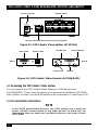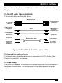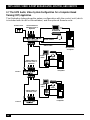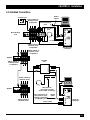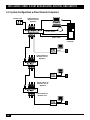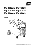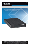
1
OCTOBER 2002
AC156A-8
AC157A-8
AC158A-REM
CAT5 Audio/Video 8-Port Broadcaster
CAT5 Audio/Video Splitter
CAT5 Audio/Video Remote
CUSTOMER
SUPPORT
INFORMATION
Order toll-free in the U.S.: Call 877-877-BBOX (outside U.S. call 724-746-5500)
FREE technical support 24 hours a day, 7 days a week: Call 724-746-5500 or fax 724-746-0746
Mailing address: Black Box Corporation, 1000 Park Drive, Lawrence, PA 15055-1018
Web site: www.blackbox.com • E-mail: [email protected]
FCC AND IC RFI STATEMENTS
FEDERAL COMMUNICATIONS COMMISSION
AND
INDUSTRY CANADA
RADIO FREQUENCY INTERFERENCE STATEMENTS
This equipment generates, uses, and can radiate radio-frequency energy, and if not
installed and used properly, that is, in strict accordance with the manufacturer’s
instructions, may cause interference to radio communication. It has been tested
and found to comply with the limits for a Class A computing device in accordance
with the specifications in Subpart B of Part 15 of FCC rules, which are designed to
provide reasonable protection against such interference when the equipment is
operated in a commercial environment. Operation of this equipment in a
residential area is likely to cause interference, in which case the user at his own
expense will be required to take whatever measures may be necessary to correct
the interference.
Changes or modifications not expressly approved by the party responsible
for compliance could void the user’s authority to operate the equipment.
This digital apparatus does not exceed the Class A limits for radio noise emission from
digital apparatus set out in the Radio Interference Regulation of Industry Canada.
Le présent appareil numérique n’émet pas de bruits radioélectriques dépassant les limites
applicables aux appareils numériques de la classe A prescrites dans le Règlement sur le
brouillage radioélectrique publié par Industrie Canada.
1
CAT5 AUDIO/VIDEO 8-PORT BROADCASTER, SPLITTER, AND REMOTE
NORMAS OFICIALES MEXICANAS (NOM)
ELECTRICAL SAFETY STATEMENT
INSTRUCCIONES DE SEGURIDAD
1. Todas las instrucciones de seguridad y operación deberán ser leídas antes de
que el aparato eléctrico sea operado.
2. Las instrucciones de seguridad y operación deberán ser guardadas para
referencia futura.
3. Todas las advertencias en el aparato eléctrico y en sus instrucciones de
operación deben ser respetadas.
4. Todas las instrucciones de operación y uso deben ser seguidas.
5. El aparato eléctrico no deberá ser usado cerca del agua—por ejemplo, cerca
de la tina de baño, lavabo, sótano mojado o cerca de una alberca, etc..
6. El aparato eléctrico debe ser usado únicamente con carritos o pedestales que
sean recomendados por el fabricante.
7. El aparato eléctrico debe ser montado a la pared o al techo sólo como sea
recomendado por el fabricante.
8. Servicio—El usuario no debe intentar dar servicio al equipo eléctrico más allá
a lo descrito en las instrucciones de operación. Todo otro servicio deberá ser
referido a personal de servicio calificado.
9. El aparato eléctrico debe ser situado de tal manera que su posición no
interfiera su uso. La colocación del aparato eléctrico sobre una cama, sofá,
alfombra o superficie similar puede bloquea la ventilación, no se debe colocar
en libreros o gabinetes que impidan el flujo de aire por los orificios de
ventilación.
10. El equipo eléctrico deber ser situado fuera del alcance de fuentes de calor
como radiadores, registros de calor, estufas u otros aparatos (incluyendo
amplificadores) que producen calor.
11. El aparato eléctrico deberá ser connectado a una fuente de poder sólo del
tipo descrito en el instructivo de operación, o como se indique en el aparato.
2
NOM STATEMENT
12. Precaución debe ser tomada de tal manera que la tierra fisica y la polarización
del equipo no sea eliminada.
13. Los cables de la fuente de poder deben ser guiados de tal manera que no
sean pisados ni pellizcados por objetos colocados sobre o contra ellos,
poniendo particular atención a los contactos y receptáculos donde salen del
aparato.
14. El equipo eléctrico debe ser limpiado únicamente de acuerdo a las
recomendaciones del fabricante.
15. En caso de existir, una antena externa deberá ser localizada lejos de las lineas
de energia.
16. El cable de corriente deberá ser desconectado del cuando el equipo no sea
usado por un largo periodo de tiempo.
17. Cuidado debe ser tomado de tal manera que objectos liquidos no sean
derramados sobre la cubierta u orificios de ventilación.
18. Servicio por personal calificado deberá ser provisto cuando:
A: El cable de poder o el contacto ha sido dañado; u
B: Objectos han caído o líquido ha sido derramado dentro del aparato; o
C: El aparato ha sido expuesto a la lluvia; o
D: El aparato parece no operar normalmente o muestra un cambio en su
desempeño; o
E: El aparato ha sido tirado o su cubierta ha sido dañada.
3
CAT5 AUDIO/VIDEO 8-PORT BROADCASTER, SPLITTER, AND REMOTE
TRADEMARKS USED IN THIS MANUAL
Any trademarks mentioned in this manual are acknowledged to be the property of the
trademark owners.
4
CONTENTS
Contents
Chapter
Page
1. Specifications . . . . . . . . . . . . . . . . . . . . . . . . . . . . . . . . . . . . . . . . . . . . . . . . . . . 6
2. Introduction . . . . . . . . . . . . . . . . . . . . . . . . . . . . . . . . . . . . . . . . . . . . . . . . . . . . 8
2.1 Description . . . . . . . . . . . . . . . . . . . . . . . . . . . . . . . . . . . . . . . . . . . . . . . . . . 8
2.2 Features. . . . . . . . . . . . . . . . . . . . . . . . . . . . . . . . . . . . . . . . . . . . . . . . . . . . . 8
2.3 Typical Applications. . . . . . . . . . . . . . . . . . . . . . . . . . . . . . . . . . . . . . . . . . . 9
2.4 What the Package Includes . . . . . . . . . . . . . . . . . . . . . . . . . . . . . . . . . . . . . 9
3. Installation . . . . . . . . . . . . . . . . . . . . . . . . . . . . . . . . . . . . . . . . . . . . . . . . . . . . 11
3.1 The Multi-Functional System . . . . . . . . . . . . . . . . . . . . . . . . . . . . . . . . . . 11
3.2 The CAT5 Audio/Video System Units . . . . . . . . . . . . . . . . . . . . . . . . . . . 11
3.3 Expanding the CAT5 Audio/Video System . . . . . . . . . . . . . . . . . . . . . . . 12
3.4 Pre-Installation Instructions . . . . . . . . . . . . . . . . . . . . . . . . . . . . . . . . . . . 12
3.5 The CAT5 Audio/Video System Cables . . . . . . . . . . . . . . . . . . . . . . . . . . 13
3.6 Power Supply . . . . . . . . . . . . . . . . . . . . . . . . . . . . . . . . . . . . . . . . . . . . . . . 13
3.7 The CAT5 Audio/Video System Configuration
for a Computer-Based Training (CBT) Application . . . . . . . . . . . . . . 14
3.8 Detailed Connections . . . . . . . . . . . . . . . . . . . . . . . . . . . . . . . . . . . . . . . . 15
3.9 System Configuration without Remote Computers. . . . . . . . . . . . . . . . . 16
4. Operation . . . . . . . . . . . . . . . . . . . . . . . . . . . . . . . . . . . . . . . . . . . . . . . . . . . . . 17
4.1 The Control Unit . . . . . . . . . . . . . . . . . . . . . . . . . . . . . . . . . . . . . . . . . . . . 17
4.1.1 Broadcast to All . . . . . . . . . . . . . . . . . . . . . . . . . . . . . . . . . . . . . . . . . 17
4.1.2 Dark All . . . . . . . . . . . . . . . . . . . . . . . . . . . . . . . . . . . . . . . . . . . . . . . 17
4.2 Adjusting the Picture Quality . . . . . . . . . . . . . . . . . . . . . . . . . . . . . . . . . . 17
Appendix. Troubleshooting . . . . . . . . . . . . . . . . . . . . . . . . . . . . . . . . . . . . . . . . . 18
A.1 Calling Black Box . . . . . . . . . . . . . . . . . . . . . . . . . . . . . . . . . . . . . . . . . . . . 18
A.2 Shipping and Packaging . . . . . . . . . . . . . . . . . . . . . . . . . . . . . . . . . . . . . . 18
5
CAT5 AUDIO/VIDEO 8-PORT BROADCASTER, SPLITTER, AND REMOTE
1.Specifications
Resolution: Up to 1600 x 1200 @ 75 Hz
Input/Output Video Signals: Analog signal red, green, blue 0.7v p-p 75 ohm
Sync: TTL compatible
Horizontal/Vertical Sync Polarity: Positive/Negative
System Cable: CAT5 shielded twisted pair (STP) cable
Maximum Distance: 360 ft. (109.7 m)
Audio: Mono
Temperature Tolerance: Operating: Up to 122°F (50°C); Storage: -40 to +158°F
(-40 to 70°C)
Connectors:
AC156A-8: VGA In: (1) HD15 male;
VGA Out: (1) HD15 female;
System Out: (8) shielded RJ-45;
Sound card: (2) 3.5-mm In/Out jacks;
Microphone/Headphone: (2) 3.5-mm In/Out jacks;
Controller: (1) 8-pin mini-DIN female;
AC157A-8: System In: (1) shielded RJ-45;
System Out: (1) shielded RJ-45;
AC158A-REM: System In: (1) shielded RJ-45;
CPU VGA: (1) HD15 male;
Screen: (1) HD15 female;
Audio In/Out: (2) 3.5-mm jacks
Cables: AC156A-8: Control unit: (1) 3-ft. (0.9-m) cable to 8-pin mini-DIN
connector;
Broadcaster unit: (1) 5-ft. (1.5-m) VGA cable with HD15 male to HD15 female,
(2) 4-ft. (1.2-m) stereo cables with 3.5-mm plug to 3.5-mm plug;
AC157A-8: No cables;
AC158A-REM: (1) 2.5-ft. (0.8-m) VGA cable with HD15 male to HD15 female
connectors, (2) audio cables with (2) 3.5-mm plugs to (1) 3.5-mm plug and
(1) 3.5-mm jack
6
CHAPTER 1: Specifications
Power: AC156A-8 and AC157A-8: 12-VDC external power adapter and power cord;
AC158A-REM: From previous unit
Size: AC156A-8: 6.9"H x 3.8"W x 1.7"D (17.5 x 9.7 x 4.3 cm);
AC157A-8: 4.6"H x 3.8"W x 1.7"D (11.7 x 9.7 x 4.3 cm);
AC158A-REM: 1.3"H x 3.1"W x 0.9"D (3.3 x 7.9 x 2.3 cm)
Weight: AC156A-8, AC157A-8: 2 lb. (0.9 kg); AC158A-REM: 0.6 lb. (0.3 kg)
7
CAT5 AUDIO/VIDEO 8-PORT BROADCASTER, SPLITTER, AND REMOTE
2. Introduction
2.1 Description
Broadcast a single audio/video source to up to 512 remote display stations. The
CAT5 Audio/Video System broadcasts high-resolution video and audio over CAT5
cable to multiple display stations in real time. You can place the remote display
stations up to 360 ft. (109.7 m) away from the source. Since the CAT5 system is a
pure hardware solution, it provides real-time screen transfer without loss of screen
quality. Broadcast the source screen at high video resolution—up to 1600 x 1200
@ 75 Hz!
The CAT5 Audio/Video System consists of these components:
• (1) CAT5 Audio/Video 8-Port Broadcaster (AC156A-8) to connect to the
audio/video source. You must have one of these.
• (1) or more CAT5 Audio/Video Splitters (AC157A-8) to expand and boost the
system. You may or may not need one of these. You can have up to 72 splitters.
• (1) CAT5 Audio/Video Remote (AC158A-REM) for each remote
screen/computer. You need at least one of these (but could have as many as
512—for 512 users, you’d also need 72 splitters).
Category 5 shielded twisted-pair (STP) cables connect the CAT5 Audio/Video
system. The CAT5 Audio/Video Remote units (AC158A-REM) can be up to 360 ft.
(109.7 m) away from the Broadcaster (AC156A-8).
2.2 Features
• Remote display and control lets you extend your information/ideas to a
distance of 360 ft. (109.7 m) without making any changes or buying new
computer equipment.
• CAT5 cable technology is plug-and-play and produces no cable clutter.
• Monitor the connection at a local unit.
• No power required at the remote unit.
• Buy only the number of remote units you need.
• Online updates and troubleshooting.
8
CHAPTER 2: Introduction
• All required cables are included, so installation is quick and easy.
• High-resolution video support of up to 1600 x 1200 @ 75 Hz makes it ideal for
display on a large screen.
2.3 Typical Applications
• Broadcast display application: An ideal solution for a wide range of multiscreen applications. Give real-time data updates at airports, train/bus stations,
stock exchanges, etc.; or broadcast entertainment/advertisements in stores,
restaurants, etc.; or for multiple-location security monitoring.
• Computer classroom application: Use the system to send a teacher’s screen
with audio to all student monitors/speakers or darken all screens. This
application works with or without computers connected to each CAT5
Audio/Video Remote (AC158A-REM).
2.4 What the Package Includes
If you ordered the CAT5 Audio/Video 8-Port Broadcaster (AC156A-8), you should
have received the following items:
• (1) CAT5 Audio/Video Broadcaster
• (1) Control unit
• (1) VGA cable
• (2) Stereo audio cables
• (1) Power supply
• (1) Power cord
• This users’ manual
If you ordered the CAT5 Audio/Video Splitter (AC157A-8), you should have
received the following items:
• (1) CAT5 Audio/Video Splitter
• (1) Power supply
• (1) Power cord
• (3) Stickers to label the STP cable
• This users’ manual
9
CAT5 AUDIO/VIDEO 8-PORT BROADCASTER, SPLITTER, AND REMOTE
If you ordered the CAT5 Audio/Video Remote (AC158-REM), you should have
received the following items:
• (1) CAT5 Audio/Video Remote
• (1) VGA cable
• (1) Audio cable
• (3) Stickers to label the STP cable
If anything is missing or damaged, please contact Black Box at 724-746-5500.
10
CHAPTER 3: Installation
3. Installation
3.1 The Multi-Functional System
You can use the CAT5 Audio/Video system in the following ways:
A. Without the control unit: The CAT5 Audio/Video Broadcaster constantly
broadcasts a computer screen with audio to all remote monitors/speakers.
B. With the control unit:
• Broadcast a computer screen with audio to all remote monitors/speakers.
• Darken all remote screens (audio broadcast is unaffected).
• Release the remote screens to allow local access (when remote computers
are connected).
The screen dark function is useful when carrying out maintenance, when
changing the broadcast program, or for grabbing students’ attention in a
classroom environment.
With both applications, you can broadcast the video at resolutions of up to 1600 x
1200 @ 75 Hz, depending on the cable length.
3.2 The CAT5 Audio/Video System Units
The following illustrations show the Broadcaster, Video Splitter, and Remote units.
Power connector
Control unit
port
System cables
Monitor
Video cable
Audio cables
Microphone and
speaker
Figure 3-1. CAT5 Audio/Video 8-Port Broadcaster (AC156A-8).
11
CAT5 AUDIO/VIDEO 8-PORT BROADCASTER, SPLITTER, AND REMOTE
Power connector
System cables
System cable from Broadcaster or previous Splitter
Figure 3-2. CAT5 Audio/Video Splitter (AC157A-8).
Video cable
Headphones
System cable
Picture adjuster
Side A
Side B
Sound card
Monitor
Figure 3-3. CAT5 Audio/Video Remote (AC158A-REM).
3.3 Expanding the CAT5 Audio/Video System
You can expand the CAT5 Audio/Video System to 512 Remote units
(AC158A-REM). This is done by having up to two levels of Splitters (AC157A-8).
Each Splitter on level 2 can have 8 Remote units connected to it (see Figure 3-5).
3.4 Pre-Installation Instructions
NOTE
In the CAT5 Audio/Video System, the CAT5 cables carry electrical
power. DO NOT connect them to any other device! To avoid this, we
recommend that you attach the provided stickers to the ends of each
CAT5 cable.
12
CHAPTER 3: Installation
Place cables away from fluorescent lights, air conditioners, and machines that are
likely to generate electrical noise.
3.5 The CAT5 Audio/Video System Cables
The included cables are illustrated below.
Broadcaster and
Remote VGA cable
To computer’s
video card
To Broadcaster
computer’s
microphone
port
Broadcaster audio
cables
To Broadcaster
computer’s
speaker port
To Broadcaster’s
or Remote’s
video In port
To Broadcaster’s
sound card
microphone port
To Broadcaster’s
sound card
speaker port
To Remote
computer’s
microphone port
Remote audio cable
To microphone
connector
To Remote’s
audio In port
To Remote
computer’s
speaker port
Figure 3-4. The CAT5 Audio/Video System cables.
THE REMOTE VIDEO AND AUDIO CABLES
The Remote video and audio cables are only used when the CAT5 Audio/Video
Remote is connected to a computer.
3.6 Power Supply
Connect the Broadcaster and Splitters to the power supply with the power adapters
and power cords provided. The Remote units do not require an external power
supply.
13
CAT5 AUDIO/VIDEO 8-PORT BROADCASTER, SPLITTER, AND REMOTE
3.7 The CAT5 Audio/Video System Configuration for a Computer-Based
Training (CBT) Application
The illustration below shows the system configuration with the control unit (which
is included with the 8-Port Broadcaster) and the optional Remote units.
Control unit
CAT5 cables to
Remote units or
Splitters
Audio cables
Video cable
Broadcaster
computer
Video
cable
Audio
cable
CAT5 cables to
Remote units or
Splitters
Remote
computer
Level 1
Video
cable
Audio
cable
CAT5 cables to
Remote units
Level 2
14
Remote
computer
CHAPTER 3: Installation
3.8 Detailed Connections
Control unit
Broadcast
to all
CAT5 cables to
Remote units
or Splitters
To microphone
port
Audio
cables
To speaker
port
Broadcaster
unit
To
mic.
port
To speaker port
CAT5 cables to
Remote units
or Splitters
Video cable
Broadcaster
computer
CAT5 cables to
Remote units
or Splitters
Splitter
Splitter
CAT5 cables to
Remote units
or Splitters
Remote
unit
CAT5 cables to
Remote units
Microphone
connector to pink
audio cable connector
Splitter
CAT5 cables to
Remote units
Pink connector to
microphone port;
Orange connector
to speaker port
Audio
cable
Video cable
Remote
computer
15
CAT5 AUDIO/VIDEO 8-PORT BROADCASTER, SPLITTER, AND REMOTE
3.9 System Configuration without Remote Computers
Control unit
CAT5 cables to
Remote unit or
Splitters
Audio cables
Video cable
Broadcaster
computer
CAT5 cables to
Remote unit or
Splitters
CAT5 cables to
Remote unit or
Splitters
CAT5 cables to
Remote unit
16
CHAPTER 4: Operation
4. Operation
Once connected, the CAT5 Audio/Video System broadcasts to all monitors/
speakers.
4.1 The Control Unit
The control unit, which is included with the 8-Port Broadcaster, is shown below.
Broadcast
to all
To Broadcaster
unit’s control port
Figure 4-1. Control unit.
With the control unit, you can carry out the following functions: Master to all or
Dark all.
4.1.1 BROADCAST TO ALL
Press the Broadcast to all button to send the Broadcaster’s screen with audio to all
remote monitors/speakers. The LED above the button will light.
Press the button again to release the remote screens.
4.1.2 DARK ALL
Press the Dark all button to darken all remote screens. The LED above the button
will light. (This does not affect audio broadcasting.)
Press the button again to release the remote screens.
4.2 Adjusting the Picture Quality
To adjust the picture quality, use a small screwdriver to turn the Picture adjuster on
the Remote unit. (See Figure 3-3 in Chapter 3.)
17
CAT5 AUDIO/VIDEO 8-PORT BROADCASTER, SPLITTER, AND REMOTE
Appendix. Troubleshooting
A.1 Calling Black Box
If you determine that any component of your CAT5 Audio/Video System is
malfunctioning, do not attempt to alter or repair the unit. It contains no userserviceable parts. Contact Black Box at 724-746-5500.
Before you do, make a record of the history of the problem. We will be able to
provide more efficient and accurate assistance if you have a complete description,
including:
• the nature and duration of the problem.
• when the problem occurs.
• the components involved in the problem.
• any particular application that, when used, appears to create the problem or
make it worse.
A.2 Shipping and Packaging
If you need to transport or ship any component of your CAT5 Audio/Video
System:
• Package it carefully. We recommend that you use the original container.
• If you are shipping any component of your CAT5 Audio/Video System for
repair, make sure you include everything that came in the original package.
Before you ship, contact Black Box to get a Return Authorization (RA)
number.
18
© Copyright 2002. Black Box Corporation. All rights reserved.
1000 Park Drive
•
Lawrence, PA 15055-1018
•
724-746-5500
•
Fax 724-746-0746