1
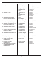
DIAGNOSTIC
SERVICE MANUAL
REVISION:
Form No. 3308058.019 8/04
(Replaces 3308058.001)
©2004 Dometic Corporation
LaGrange, IN 46761
1
Contents
PAGE NO.
WeatherPro & Oasis Elite Symptom/Cause ........................................... 3
SECTION 1- Wiring .................................................................................. 4-6
1.1
12VDC Supply Wire
................................................................. 4
1.2
Wire From Control Box To Awning ................................................... 4
1.3
Wire Inside Hardware Channel (WeatherPro Only) ......................... 4
1.4
Motor Connection & Motor ............................................................... 5
1.5
Wire To Remote Switch ................................................................... 5
1.6
Wind Sensor Cable .......................................................................... 5
1.7
Ignition Interlock wire ....................................................................... 6
SECTION 2- WeatherPro Wind Sensor ................................................... 6
2.1
Wind Sensor .................................................................................... 6
SECTION 3- Control Box ......................................................................... 6-8
3.1
Circuit Board ................................................................................... 6-8
3.2
Control Box Rocker Switch .............................................................. 8
3.3
Wind Sensor Toggle Switch ............................................................. 8
3.4
Wiring Diagram ................................................................................ 7
SECTION 4- Remote Switch .................................................................... 9
4.1
Remote Switch ................................................................................ 9
SECTION 5- Remote Key FOB ................................................................. 9
5.1
Remote Key FOB ............................................................................. 9
5.2
FOB Programming ........................................................................... 9
SECTION 6- WeatherPro Auxiliary Cable .............................................. 10
6.1
Auxiliary Cable ................................................................................ 10
SECTION 7- WeatherPro Emergency Retract Procedure ..................... 10
7.1
Emergency Retract Procedure ....................................................... 10
SECTION 8- WeatherPro Fabric, Roller Tube, Torsion Assembly
& Weathershield Replacement ............................................................. 10-15
8.1
General Instructions ....................................................................... 10
8.2
Awning Removal ........................................................................... 10-11
8.3
Left Hand Torsion Removal .......................................................... 11-12
8.4
Right Hand Drive Assembly Removal ............................................. 12
8.5
Fabric Removal From Roller Tube .................................................. 12
8.6
Weathershield Assembly Removal And Replacement .................. 12-13
8.7
Reinstall Fabric On Roller Tube ...................................................... 13
8.8
Torsion Assembly Replacement.................................................... 13-14
8.9
Left Hand Torsion Assembly Winding ........................................... 14-15
SECTION 9- Wiring Diagram ................................................................. 15-16
9.1
Wiring Diagram ............................................................................ 15-16
2
SYMPTOM
CAUSE
LOCATION
1. Awning will not open
1.
2.
3.
4.
5.
6.
7.
12VDC Supply Wire
Fuse
Ignition Interlock (WeatherPro)
Wiring/Connections
Wind (WeatherPro)
Circuit Board Wiring
Motor
Section 1.1
Section 3.1.3
Section 1.7 & 3.1.7
Section 1.2, 1.3, 1.4.1, 1.5 & 9.1
Section 2.1 & 3.3
Section 3.1-3.4
Section 1.4.2
2. Awning will not close
1.
2.
3.
4.
5.
12VDC Supply Wire
Fuse
Wiring/Connections
Circuit Board Wiring
Motor
Section 1.1
Section 3.1.3
Section 1.2, 1.3, 1.4, 1.5, & 9.1
Section 3.1-3.4
Section 1.4.2
3. Awning works with remote switch
but not key FOB (WeatherPro Only)
1. Distance
2. Key FOB Battery
3. Key FOB Programming
Section 5.1
Section 5.1
Section 5.2
4. Awning works with key FOB but not
remote switch (WeatherPro Only)
1. Circuit Board Wiring
2. Switch
Section 3.1.5 & 3.1.6
Section 4.1
5. Awning will open when ignition key is in
the on position (WeatherPro Only)
1. Wiring/Connections
2. Circuit Board
Section 1.7
Section 3.1.7
6. Awning works in opposite direction
1. Wiring/Connections
2. Circuit Board Wiring
3. Switch
Section 1.5
Section 3.1.5 & 3.1.6
Section 4.1 & 3.2
7. WeatherPro awning works when Oasis
Elite should or visa versa
1. Wiring/Connections
2. Circuit Board Wiring
Section 1.2 & 9.1
Section 3.1.4
8. Awning does not close during high wind
conditions
1. Wind Sensor Switch Off
2. Wind Sensor Wiring
3. Wind Sensor
Section 3.3
Section 1.6 & 3.1.8
Section 2.1
9. Beeping sound coming from control box
(WeatherPro Only)
1. Wind Sensor Wiring
2. Wind Sensor
Section 3.1.8 & 3.1.9
Section 2.1
10. Auxiliary Close/Open awning
(WeatherPro Only)
1. No 12VDC in RV
Section 6.1
11. Emergency Close Awning
(WeatherPro Only)
1. No 12VDC Available
2. Awning Inoperable
Section 7.1
Section 7.1
12. Fabric, Roller Tube, Torsion Assembly
and Weathershield Replacement
(WeatherPro Only)
Section 8.1- 8.9
3
SECTION 1 WIRING
3307930 & 3309114 Control Box Kit Using
Universal MATE-N-LOKR Soft Shell Connector
FIG. 1.1A
Yellow (10)
WeatherPro
Remote Switch
Brown (15)
Green (5)
Ignition
Isolator
Red 12VDC + (1)
12VDC Supply Wire
1.1.1 The 12VDC supply wire must be run from
the 12VDC supply source to the Control
Box. It is recommended that these wires
be RED+ and Black– 12 gauge wires. This
needs to be on a separate 15 amp circuit.
See FIG. 1.1A & 1.1B.
1.1.2 To ensure proper operation, the control
box must have a minimum of 12.5 VDC at
the control box during operation. Check
voltage output on the Red and Black wire
at the control box. If voltage is below 12.5,
check voltage at supply, If OK it may be
necessary to increase the wire size going
to the control box. See FIG. 1.1A.
Black 12VDC - (2)
1.1
Yellow/White (9) Oasis
Elite
Brown/White (14) Remote
Green/White (4) Switch
Pink (3)
13
14
15
10
11
12
7
8
9
4
5
6
1
2
3
Red (13)
Blue or BlK/Wh (7)
1
2
Black (8)
AMP 2-Pin
Connector
WeatherPro
Awning
Main Arm
Right Side
Red/White (12)
2
1
Oasis
Elite
FRTA
AMP UNIVERSAL MATE-N-LOK R
Soft Shell Connector
FIG. 1.1B
13
14
15
10
11
12
7
8
9
4
5
6
1
2
3
12VDC
Power Supply
Wind Sensor Switch
ENABLE (ON)
DISABLE (OFF)
+12.5
VDC
Auto Resettable Fuse
Used On Some Models
15 AMP
Breaker
Open
*FUSE LOCATED INSIDE
Close
Red +
BlackCable to Wind Sensor
18-20 Gauge
(18 Foot Maximum)
Open
Black 1
Red 2
Green 3
Yellow 4
*FUSE LOCATED INSIDE
Cable Between MATE-N-LOK
4 Pin Connectors
Customer Supplied
18-20 Gauge
(18 Foot Maximum)
Close
1.1.3 If the control is the part number 3307930
& 3309114 the voltage can be checked
on the pins (1) and (2) of the 15 pin MATEN-LOK® plug. Pin (1) is DC+ and pin (2) is
DC-. See FIG. 1.1B
1.2 Wire From Control Box to Awning. Arm Assembly (WeatherPro) and Awning Motor (Oasis Elite)
A Red and Black Wire (WeatherPro) Red/White
and Blue or Black/White wire (Oasis Elite) of
adequate size must be run between the control
box and the awning. To avoid voltage drop follow the chart below to determining the proper
size wire to be used.
Wire Length
Wire Size
10' & Under
14 Gauge
11' to 30'
12 Gauge
Over 30'
10 Gauge
FIG. 1.2
Location
Pin 1
Pin 2
Pin 3
Pin 4
Pin 5
Pin 6
Pin 7
Pin 8
Pin 9
Pin 10
Pin 11
Pin 12
Pin 13
Pin 14
Pin 15
Pig Tail
for Motor
Black
Wire Size
12 Gauge
12 Gauge
16 Gauge
16 Gauge
16 Gauge
Blue or Blk/Wh
Black
Yellow/White
Yellow
See chart in 1.2
See chart in 1.2
16 Gauge
16 Gauge
Red/White
Red
Brown/White
Brown
See chart in 1.2
See chart in 1.2
16 Gauge
16 Gauge
FIG. 1.3
Red
Cable
Black or Blue
Pig Tail to
Control Box
End
Wire Color
Red
Black
Pink
Green/White
Green
1.3 Wire Inside Hardware Channel (WeatherPro Only)
To make the connection between the wire run in
1.2 and the awning motor there is a cable run in
the hardware from the bottom to the top. Check
this wire for pinches or breaks. If wire is defective replace with new harness. See FIG. 1.3.
WeatherPro
Main Arm
Right Side
Red
Pin Functions
12+VDC
12- VDC
Ignition Isolator
Oasis Elite Remote Switch
WeatherPro Remote Switch
Blank
Oasis Elite Motor (-12VDC)
WeatherPro Motor (-12VDC)
Oasis Elite Remote Switch
WeatherPro Remote Switch
Blank
Oasis Elite Motor (+12VDC)
WeatherPro Motor (+12VDC)
Oasis Elite Remote Switch
WeatherPro Remote Switch
Black
Red/White
Red
Black
Blue or Blk/Wh
Red
Open
Oasis Elite
Motor
Right Arm
Assembly
Cable
*FUSE LOCATED INSIDE
Close
4
1.4 Motor Connection & Motor
1.4.1 The awning motor is connected to the
hardware at the top of the awning hardware front channel. Make sure connection is tight and corrosion free.
1.4.2 Disconnect the motor from the hardware
connection. See FIG. 1.4. Apply DC voltage directly to the motor wire connector.
A minimum of 12.5 VDC is required to operate the motor. If motor does not turn it is
defective and the drive assembly must be
replaced.
FIG. 1.5
Green
Brown
EXTEND
RETRACT
Yellow
Green
Motor
Arm
Brown
White
Green/ White
Pig Tail to
Remote Switch
Yellow/White
Brown/White
Pig Tail to
Remote Switch
Yellow
Brown
FIG. 1.4
WeatherPro
Remote
Switch
Green/ White
EXTEND
RETRACT
Yellow/White
Oasis Elite
Remote
Switch
WeatherPro
Motor Connection
Open
*FUSE LOCATED INSIDE
Close
FIG. 1.6A
4 Conductor
FLAT Cable
Connections
1.5 Wire To Remote Switch
1.5.1 On control 3307916.00, the remote switch
is connected to the control box with three
(3) 16 gauge wires. These are Brown,
Yellow, Green for WeatherPro and Brown/
White, Yellow/White, Green/White for
Oasis Elite. The switch end of the wire will
be connected to the switch by means of
1/4" insulated tab connectors. The control box end has a pig tail to connect the
control box to these three wires. See
switch for correct wiring. Make sure connections are tight and corrosion free. See
FIG. 1.5.
1.5.2 The 3307930 & 3309114 Control box has
three (3) 16 gauge wires coming out of a
15 pin MATE-N-LOK®. These are Brown,
Yellow, Green for WeatherPro and Brown/
White, Yellow/White, Green/White for
Oasis Elite. See FIG. 1.1B and chart for
pin location.
Pin 1
RJ-11-6C4P
Connector
1.6 Wind Sensor Cable
The wind sensor is connected to the control box
with a FLAT four (4) conductor cable terminated
on both ends with an RJ-11-6C4P telephone connector. Maximum length is 18'. This cable is polarity sensitive and must be assembled as shown.
A standard telephone cable will not work.
Cable can be checked with a Dometic
3107127.007 cable tester. If cable is found to be
defective replace with a cable no longer than 18'.
See FIG. 1.6A & 1.6B
Flat Four Conductor Cable
5
Black
Red
Green
Yellow
Black
Red
Green
Yellow
FIG. 1.6B
Note: The 3307930 & 3309114 control box uses two four
pin MATE-N-LOK® connectors in conjunction with the RJ11-6C4P plugs. If the 3107127.007 cable tester shows a
defect, check these connections for problems. See FIG.
1.1B & 3.4B
FIG. 2.1
Wind Sensor Switch
Wind Sensor
ENABLE
DISABLE
Open
ENABLE
Pink
Wind Sensor
DISABLE
1.7 Ignition Interlock Wire
1.7.1 When using the 3307916 Control box, the
ignition Interlock wire when correctly installed will prevent the awning from opening when the ignition key is in the on position. This wire is routed between the ignition isolator (Pink) wire of the control box
to the ignition isolator of the vehicle. It
should be a 16 gauge wire. Make sure
wire connections are tight and corrosion
free. See FIGS. 1.1A & 1.7.
FIG. 1.7
Control Box
Note: Dometic uses two different control box configurations for the WeatherPro Awnings. The first is part number
3307916 and has 6 molded rubber plug harnesses coming out of a strain relief. See FIG. 3.4A. The second is part
numbers 3307930 & 3309114 and has one (1) 15 pin
MATE-N-LOK® with 13 wires going to the strain relief and
it has a 4 pin connector used in the wind sensor cable.
See FIG. 1.1B & 3.4B.
3.1 Circuit Board
The circuit board can be checked out by the process of elimination. Make sure there is 12.5 VDC
going into the circuit board.
3.1.1 Disconnect all pig tails coming out of the
(3307916) control box. Control box
3307930 & 3309114 with 15 wire plug
must remain connected.
3.1.2 Check for 12.5 VDC (minimum) at T1 (red
+) and T3 (black –) on circuit board.
3.1.3 Check for 12.5 VDC (minimum) on each
leg of fuse. Place the negative lead of the
volt meter on T3 and check each leg of
the fuse with the positive lead. This should
read 12.5 VDC on each leg. Replace if
defective.
Note: Some control boxes contain an auto-reset fuse.
3.1.4 Check for voltage at the WeatherPro output to motor pigtail on control box 3307916
(Red & Black wire), and on the 15 pin connector on control box 3307930 & 3309114
check for voltage at Red (pins 8) and Black
(pin 13).
First, press and hold the rocker switch in
the open position. Place the negative lead
of the digital volt meter on the Black wire
position of the pigtail and the positive lead
of the volt meter on the Red wire position
of the pigtail. The meter should read (–)
negative 12.5 VDC (minimum). Do not
move the volt meter leads and press and
hold the rocker switch in the close position. The meter should read (+) positive
12.5 VDC (minimum).
+ Ignition
Isolator
*FUSE LOCATED INSIDE
Close
1.7.2 When the 3307930 & 3309114 control box
is used the pink wire is routed from the 15
pin connector to the ignition isolator of the
vehicle. It should be a 16 gauge wire.
Make sure wire connections are tight and
corrosion free. See FIGS. 1.1B & 3.4B.
SECTION 2 Wind Sensor
2.1 The wind sensor monitors the wind speed (1422 MPH) and sends a signal to the control box if
wind speeds exceeds the preset setting. The correct position of the winds sensor is critical. It
should be within 3 feet of the right side top mounting bracket and away from other objects. To check
out the wind sensor, open the awning and place
the wind sensor switch in the ENABLE (ON) position. You can create sufficient amount of wind
by placing a standard hair dryer approximately 6
inches away from the wind sensor with the dryer
set on HIGH and NO HEAT. The awning should
close automatically. See FIG. 2.1.
SECTION 3 Control Box
The control box is the heart of the system and
contains a fuse, rocker switch, wind sensor toggle
switch & circuit board.
6
Cable to Wind Sensor
(18 Foot Maximum)
WeatherPro
Rocker Switch
T11
T14 T15
T12 T13
Open
Yellow
Green
T18
T16 T17
Green
Brown
Blue
Brown White
FUSE
15 AMP
Blue
T19 T20
Green/White
T10
Yellow/White
WeatherPro
Remote
Switch
Pink
3307916 Control Box
FIG. 3.4A
Oasis Elite
Remote
Switch
Close
Yellow
Brown
T1
T2
T3
T4
T5
T6
Red/White
WeatherPro
Output To
Motor
12 VDC
Supply
T9
Blue Or Blk/Wh
Red
Black
Red 12VDC +
Wind Sensor Switch
ENABLE (ON)
DISABLE (OFF)
T8
T7
Oasis Elite
Output To
Motor
Black 12VDC -
15 Pin MATE-N-LOK® Connector
FIG. 3.4B
Location
Pin 1
Pin 2
Pin 3
Pin 4
Pin 5
Pin 6
Pin 7
Pin 8
Pin 9
Pin 10
Pin 11
Pin 12
Pin 13
Pin 14
Pin 15
AMP UNIVERSAL MATE-N-LOK R
Soft Shell Connector
3307930 & 3309114
Control Box
Plug ID Tab
13
14
15
10
11
12
7
8
9
4
5
6
1
2
3
Cable Between Two
MATE-N-LOK 4 Pin
Connectors Customer
Supplied
1
2
3
4
Cable to Wind
Sensor
(18 Foot Maximum)
WeatherPro
Rocker Switch
Pin Functions
12+VDC
12- VDC
Ignition Isolator
Oasis Elite Remote Switch
WeatherPro Remote Switch
Blank
Oasis Elite Motor (-12VDC)
WeatherPro Motor (-12VDC)
Oasis Elite Remote Switch
WeatherPro Remote Switch
Blank
Oasis Elite Motor (+12VDC)
WeatherPro Motor (+12VDC)
Oasis Elite Remote Switch
WeatherPro Remote Switch
Wire Color
Red
Black
Pink
Green/White
Green
Blue or Blk/Wh
Black
Yellow/White
Yellow
Red/White
Red
Brown/White
Brown
4 Pin MATE-N-LOK®
Connector
Location
Wire Color
Pin 1
Pin 2
Pin 3
Pin 4
1
2
T16 T17
T19 T20
Plug ID Tab
Brown
Green
Blue
15 AMP
FUSE
Blue
T1
T2
T3
T4
T6
T7
Red
Black 12VDC -
T5
All Plugs Shown From
Wire Or Back Side
T8
Blue Or BlK/Wh
Black
Yellow
Brown
Red/White
Red/White
Close
Wind Sensor
Switch
ENABLE (ON)
DISABLE (OFF)
T18
Blue
T15
Grn/Wh
T14
Yel/Wh
T13
T12
Pink
T11
Blue
T10
Brn/Wh
Green
Yellow
Red 12VDC +
Open
3
4
T9
Auto-Reset Fuse
On Some Control
Boxes
7
Black
Red
Green
Yellow
3.1.5
WeatherPro Remote Switch
a. To check the WeatherPro (3307916
Control Box) remote switch connection (Brown, Green, & Yellow) wires
in a 3 pin black molded plug, use a
jumper wire and connect the Yellow
to Brown. You should hear the relay
click. Then connect the Green to
Brown and you should hear another
click.
b. To check the 3307930 & 3309114
control box remote switch use a
jumper wire and connect the yellow
(pin 10) to Brown (pin 15). The relay
should click inside the control box.
Then connect the Brown (pin 15) to
Green (pin 5) and another click will
be heard.
3.1.6 Oasis Elite Remote Switch
a. Check the Oasis Elite (3307916 control box) remote switch (wire in a 3
pin black molded plug), and the output to motor wire (in a 2 pin black
molded plug) at the same time. The
remote switch wires are Brown/White,
Green/White and Yellow/White. The
output to motor wire is Red/White and
Blue or Black/White. Connect the
positive lead of the digital volt meter
to the Red/White wire position of the
pigtail and the negative to the Blue or
Black/White wire position of the pigtail. Jump across the Yellow/White
and brown/White wire. You should
hear the relay click and the voltage
meter should read (–) negative 12.5
VDC (minimum). Jump across the
Green/White and the Brown/White
wire. You should hear another relay
click and the volt meter should read
(+) positive 12 VDC (minimum).
b. Check the Oasis Elite 3307930 &
3309114 control box remote switch
and the output to the motor at the
same time. The remote switch wires
are Brown/White (pin 14), Green/
White (pin 4) and Yellow/White (pin
9). The output wires to the motor are
Red/White (pin 12) and Blue or Black/
White (pin 7). Connect the positive
lead of the digital volt meter to the
Red/White (pin 12) wire position of the
pigtail and the negative to the Blue or
Black/White (pin 7) wire position of the
pigtail. Jump across the Yellow/White
(pin 9) and brown/White (pin 14) wire.
You should hear the relay click and
the voltage meter should read (–)
negative 12.5 VDC (minimum). Jump
across the Green/White (pin 4) and
the Brown/White (pin 14) wire. You
should hear another relay click and
the volt meter should read (+) positive 12 VDC (minimum).
3.1.7 Ignition Interlock Function
a. To check the ignition interlock function on control box 3307916
(WeatherPro Only), apply (+) positive
12 VDC to the Pink ignition interlock
wire. Redo test in Step 3.1.4. There
should be no readings or relay clicks
when the rocker switch is placed in
the open position or the key FOB open
button is pressed.
b. To check the ignition interlock function on control box 3307930 &
3309114 (WeatherPro Only), apply (+)
positive 12 VDC to the Pink ignition
interlock wire (pin 3). Redo test in
3.1.4. There should be no readings
or relay clicks when the rocker switch
is placed in the open position or the
key FOB open button is pressed.
3.1.8 The circuit board contains an audible
alarm to alert the user when there is a
problem with the wind sensor or wind
sensor cable. To test this alarm disconnect the FLAT four (4) conductor wind
sensor cable from the side of the control
box. Place the wind sensor switch in the
ENABLE (ON) position. The alarm should
beep from inside the control box. If this
occurs under normal operation this would
indicate a problem with the wind sensor
wire or the connection between the wire
and the circuit board or the wire and the
wind sensor.
3.1.9 Temperature Sensing
a. If the temperature is 30° F or less and
the wind sensor switch is in the ENABLE (ON) position the alarm will
sound. The awning will not open and
if it is in the open position it will automatically close. Moving the switch to
the DISABLE (OFF) position will stop
the alarm from sounding. See Section 1.6 and Section 2.1.
b. If the temperature exceedes the 105°
high range the wind sensor will continue to function. The alarm will not
sound. High winds (over 18- 22 MPH)
will close the canopy.
3.2
Control Box Rocker Switch
The awning can be operated at the control box
by using the rocker switch located on the cover
of the control box. To test the switch, press open
or close and you should hear a relay click. If after
all other circuit board checks are made and no
8
click is present switch is defective. Replace
switch.
3.3 Wind Sensor Toggle Switch
The toggle switch turns the wind sensor feature
on and off. When the switch is in the DISABLE
(OFF) position the awning will not automatically
retract if threatening winds are present. When in
the ENABLE (ON) position the awning will automatically retract if the wind exceeds the preset
setting.
If one or more of the above tests do not perform
properly the circuit board is probably defective.
Replace the control box assembly.
3.4 Wiring Diagram (See Page 7, FIG. 3.4A & 3.4B)
SECTION 5 Remote Key FOB
5.1
The remote key FOB is powered by a 12 VDC
type 23A battery. The operational range is up to
30 feet. This distance will vary depending on the
battery condition. To change the battery, remove
screw in back of key FOB and replace it with a
type 23A 12VDC battery. See FIG. 5.1.
FIG. 5.1
EXTEND
PATIO
RETRACT
EXTEND
DOOR
Battery
RETRACT
23A 12V
SECTION 4 Remote Switch
4.1 If awning does not work using the remote switch,
disconnect both the WeatherPro and the Oasis
Elite pigtail. Check for 12VDC on the control box
end of the pig tail. See Section 3.1.4 and 3.1.6. If
there is 12 VDC at this point depress the remote
switches and listen for the relays to click. If no
clicking is heard replace appropriate remote
switch. See FIG. 4.1.
5.2
FIG. 4.1
EXTEND
RETRACT
Programming Key FOB
The electronic board is susceptible to static
charge. Do not insert metal object inside control box. Damage to electronic board will occur if a short is created. Use only a nonconductive material to depress programming
button inside control box.
5.2.1 Remove four (4) screws from control box
cover and lift cover to expose circuit board.
See FIG 5.2.
5.2.2 Press and release programming button .
Programming indicator light will illuminate.
5.2.3 Press and hold the key FOB patio awning
open button for four (4) seconds.
5.2.4 Release the key FOB patio awning open
button. This completes the programming
process.
5.2.5 Place control box cover on control box and
secure with four (4) screws .
5.2.6 Test awning operation.
FIG. 5.2
Programming
Indicator Light
Patio Awning
Open Button
Programming
Indicator Light
Programming
Button
Programming
Button
9
SECTION 6 Auxiliary Cable
FIG. 7.1
In Case Of Coach 12VDC Power Failure:
6.1. The WeatherPro hardware provides an auxiliary
power cable to connect the awning motor to an
external 12 VDC power source in case of power
failure in the coach. A good external 12 VDC
power source would be an automobile battery.
Access the motor and hardware cable connection located behind the wire cover at the top of
the right hand arm. Gently squeeze the sides together to remove. Unplug the connection. See
FIG. 6.1.
Bolt
SECTION 8 WeatherPro Fabric, Roller
Tube, Torsion Assembly &
Weathershield Replacement
FIG. 6.1
8.1. General Instructions
8.1.1 The fabric roller tube assembly (referred
to in the instructions as a FRTA) consists
of a vinyl or acrylic fabric, roller tube, torsion assembly and weathershield. These
instructions will aid the service technician
to make repairs quickly and correct. The
repairs must be made by a qualified service technician. Read instructions ENTIRELY before attempting to make repairs
on the product.
Motor
Connector
10' Auxiliary
Cable
Hardware
Connector
Wire
Cover
These instructions must be read and understood before installation, adjustment, service
or maintenance is performed. This unit must
be installed by a qualified service technician.
Modification of this product can be extremely
hazardous and could result in personal injury
or property damage.
Connect the supplied 10 ft. harness directly to
the motor plug. Not the one in the hardware. Connect the other end of the 10 ft. harness to a 12
VDC battery source. The red wire goes to + and
the black to –. This will retract the awning. To
avoid motor damage disconnect battery source
immediately after awning is fully retracted. The
awning can be extended by reversing the polarity. Place the red wire on the – and the black wire
on the +. Again, remove wires immediately after
awning is fully extended.
8.2 Awning Removal
8.2.1 In all instances of fabric, roller tube or
weather shield replacement, it is necessary to unroll the fabric. A large clean and
smooth work area is required to prevent
damage to the fabric.
Note: If replacement of either torsion assembly is required
awning removal from the coach is not necessary. Proceed
to Sections 8.3 and 8.4.
8.2.2 Remove the TEK screws securing the awning fabric at each end of the awning rail.
See FIG. 8.2.2.
SECTION 7 Emergency Retract Procedure
To Manually Close Awning:
7.1 Slide the pull strap (provided) into the utility slot
of the FRTA. See FIG. 7.1.
While one person is holding onto the pull strap,
remove the bolt in the top of the right top casting.
The FRTA will roll in once the bolt is removed.
Walk the awning to the closed position. See FIG.
7.1.
Align hole where bolt was removed and drive bolt
back into top casting to secure awning.
FIG. 8.2.2
TEK Screw
Bolt must be reinstalled to prevent awning from
opening during travel. Have awning serviced by a
Dometic Service Center or a qualified service technician before attempting to open awning after this
procedure has been performed.
Remove from
Both Ends
Awning Rail
10
8.2.3
Extend or open the awning two revolutions of the FRTA. This will allow for removal of top brackets and the FTRA.
8.2.4 Pin the left hand torsion. See Section 8.3.
8.2.5 Disconnect the wire harness at the plug
by the lower mounting bracket of the right
arm assembly. In some installations the
harness may be run through a hole in the
side wall of the coach. If the hole is sealed,
use a screw driver to dig out the sealant.
Be careful not to damage wires, wall, or
the harness assembly out of the coach.
8.3
Left Hand Torsion Removal
Use extreme care. Springs under tension are
dangerous. If not controlled they will unwind
quickly. Keep hands and clothing clear of top
casting, as personal injury may result.
Note: If the awning is installed on a coach, complete the
following steps on a step ladder with the FRTA extended
two turns from the awning rail.
Note: In some installations the wind sensor wire is routed
behind the right arm assembly. Be careful not to damage.
Severe injury can result from the rapid spinof of the top casting. NEVER use bare hands
to handle a top casting under spring tension.
Arms under tension from the gas strut are
dangerous. Use extreme care. If not controlled the arms will extend quickly. Keep
hands and clothing clear of awning arms, as
personal injury may result.
8.2.6
8.3.1 Before the left arm assembly is removed
the torsion must be pinned to prevent uncontrolled unwinding of the spring.
8.3.2. Turn top casting or FRTA until the pin is
parallel with the two slots in the end cap.
See FIG. 8.3.2.
8.3.3 To pin the left hand torsion insert a 7/64"
x 2-3/4" cotter pin through the end cap
and torsion rod. Put a piece of tape over
the head of the cotter pin to prevent it from
dropping out. See FIG. 8.3.2.
The next two steps require three people.
Loosen the lag bolts holding the top and
bottom mounting brackets to the coach.
Push the arm assemblies closed and wrap
two heavy nylon wire ties around each arm
assembly to prevent them from extending during removal of the FRTA. One
should be 8 inches above the front channel cover, and the other 8 inches below
the top mounting bracket. Do both arm
assemblies. See FIG. 8.2.6.
FIG. 8.3.2
Turn FRTA Or Top Casting To
Align Slots In End Cap With Pin
Note: Bottom brackets and back channel may be riveted.
FIG. 8.2.6
Wire Tie 8”
Below Top
Bracket
Front Channel
Cover
Left Hand Torsion Shown
Slots In
End Cap
Top Bracket
Wire Tie 8”
Above Front
Channel Cover
Bottom Bracket
Cotter Pin
Insert Cotter Pin All The
Way Through End Cap
And Hole In Torsion Rod
8.2.7 While lifting the arm assemblies to support the FRTA, remove the lag bolts holding the top and bottom mounting brackets to the side wall of the coach. Slowly
walk the awning fabric out of the awning
rail.
8.2.8 Lay the FRTA on a large clean work area
to prevent damage.
8.2.9 Before removing the arm assemblies, you
must read and understand Sections 8.3
and 8.4.
Pin
Note: Do step 8.3.4 if FRTA is installed on coach. If not
installed on coach proceed to step 8.3.5.
8.3.4 Insert a wood block, between front and
back channel to space the FRTA 2 - 3
inches from the coach. Push arm assembly closed. Wrap a nylon wire tie around
arm to keep it from extending.
11
8.3.5 Remove Hex Head 1/4"-20 x 1/2" screw
that attaches arm assembly to top casting. Lift casting out of arm assembly.
8.3.6 Clamp a Vice-Grip® firmly to the top casting. See FIG. 8.3.6.
FIG. 8.3.6
8.5.2 Remove both torsions. See Sections 8.3
and 8.4 for drive assembly removal.
8.5.3 Roll the awning completely out on a clean
smooth surface.
8.5.4 With the awning laying flat, slide the roller
tube out from fabric.
Left Hand Torsion Shown
Note: Use needle nose pliers to remove the poly rope from
the groove(s) of the roller tube before removing fabric.
Top Casting
End Cap
8.6
Cotter Pin
WEATHERSHIELD ASSEMBLY REMOVAL
AND REPLACEMENT
8.6.1 Remove the two screws (one on each
side) that lock slat "A" to first slat "B". See
FIG. 8.6.1 & 8.6.3.
FIG. 8.6.1
Clamp Vise Grip®
Firmly To Top
Casting
5/16” Channel
Both Ends
8.3.7 Keep a tight hold onto the Vise Grip® while
the cotter pin is pulled out of the end cap.
8.3.8 Slowly unwind the spring tension, do not
allow rapid spin off.
8.3.9 Use the electric drill with a 3/16" drill to
remove the 3 pop rivets that secure the
end cap to the roller tube. Pull the torsion
out of the tube and remove any burrs or
rivet bodies.
Note: If the awning is installed on a coach, complete the
following steps on a step ladder with the FRTA extended
two turns from the awning rail.
8.4
Top Slat “A”
Slat “B”
5/16” Channel
Install Toward
Canopy
Sla
t“
Sla
A”
t“
Sla
B”
t“
Sla
B”
t“
B”
1s
“B t . S l
at
”
Right Hand Drive Assembly Removal
8.4.1 When the removal of the Right Hand Drive
Assembly is necessary, the left hand must
be pinned, or the FRTA will unroll and the
spring tension will be lost. See Section 8.3
1/4” Channel
Install Toward
Awning Rail
FIG. 8.6.3
Note: Do step 8.4.2 if FRTA is installed on coach. If not
installed on coach proceed to step 8.4.3.
8.5
8.4.2 Insert a wood block, between front and
back channel to space the FRTA 2 - 3
inches from the coach. Push arm assembly closed. Wrap a nylon wire tie around
arm to keep it from extending.
8.4.3 Remove Hex Head 1/4-20 x 1/2" screw
that attaches arm assembly to top casting. Remove arm assembly.
8.4.4 Use the electric drill with a 3/16" drill to
remove the 3 pop rivets that secure the
end cap to the roller tube. Pull the drive
assembly out of the tube and remove any
burrs or rivet bodies.
Fabric Removal From Roller Tube
8.51 Remove awning from coach. See Section 8.2.
Open Crimps With
Remove Screw
Screw Driver
Both Ends
Check Both Ends Of FRTA
8.6.2 Use "O" ring pliers to spread open the
crimp in the slats Slide the top slat "A" off
slat "B" (toward canopy) to allow the slat
assembly to slide off fabric. Keep for reinstall in Step 8.6.5 (unless new slat assembly is being installed). If new fabric is being
installed, lay new fabric over old one.
Check for correct size and color.
8.6.3 The new replacement weathershield/fabric will be installed as shown in FIG. 8.6.3.
Place connected slat assembly on top of
fabric.
12
Note: Make sure the 1/4" groove on all “B” slats are toward
awning rail. If new weathershield assembly is being installed, it is shipped with 6 slats. Remove the first slat "B",
it is not needed.
8.7
Note: When changing the fabric, it is vital that the same
groove(s) be used. This eliminates the need to drill any
holes. On a new roller tube, the fabric rope is placed in the
channel with the notch in its’ edge (opposite the notch in the
roller tube). See FIG. 8.7.1.
8.6.4 Use a small file and round ends of the
groove in the 5/16" end of first slat "B" and
"A". See FIG. 8.6.1 & 8.6.3.
8.6.5 Slide first slat "B" of the connected
weathershield assembly (if slat "A" was
removed in Step 8.6.2, it should be replaced) onto the poly rope in fabric located approximately 12" from awning rail
end; and, at the same time, slide slat "A"
onto poly rope located 1" from awning rail.
See FIG. 8.6.1 & 8.6.3. Slide the
weathershield onto both ropes at the same
rate.
8.6.6 Crimp both channels of the weathershield
about 3" from end of slats onto poly rope
to secure the weathershield assembly to
the fabric. It is only necessary to crimp
weathershield on one end of the FRTA.
See FIG. 8.6.3.
Re-Install Fabric On Roller Tube
8.7.1 Unfold the new fabric and lay it on top of
the existing fabric in the exact same
position. Be sure the new fabric is the
correct size and color. If roller tube is being
replaced, make sure it is the correct length
and position it with the notch located as
shown in FIG. 8.7.1.
FIG. 8.7.1
Roller
Tube
Fabric Rope
Channel
8.7.3 Guide the roller tube over the poly rope(s)
of the fabric. Be careful not to damage the
roller tube or the fabric.
8.7.4 Center the fabric on the roller tube and
hand-roll the entire assembly in the same
direction as the original fabric.
8.7.5 See Section 8.6 for weathershield replacement Steps 8.6.3 to 8.6.6. and Section
8.8, Replacing torsion assemblies.
8.8 Torsion Assembly Replacement
8.8.1 The poly ropes must be properly trimmed
and secured to the roller tube; as it can
interfere with the torsion and allow shifting
of the fabric.
8.8.2 Use pliers to pull the fabric rope toward the
center of the roller tube and push it back to
lock it in the notch on the edge of the
channel. Cut fabric rope 1" below channel.
See FIG. 8.8.2.
View
Shows Right
FIG. 8.8.2
End Of Roller Tube
Place End Cap Guide
On End Of Roller Tube
Stretch Fabric Rope
And Lock In Notch.
Trim To 1"
Trim Valance
Rope Even With
Tube
Slide Fabric and
Valance Ropes
Through Guide
Valance
Rope
Channel
8.8.3 Trim valance rope even with the edge of
roller tube. See FIG. 8.8.2.
8.8.4 Install left hand torsion
a. Slide left hand torsion assembly into
left end of roller tube. Turn end cap till
locating tabs are in place in the notch
on the roller tube. This should align
the open channel with the slot in the
end cap.
b. Secure the end cap to the roller tube
using three (3/6" x 3/8") pop rivets.
See Section 8.9; winding left hand
torsion.
Open
Channel
Notch
End Cap Guide
8.7.2 Dometic requires the use of the end cap
guide to prevent damage to the fabric,
when replacing the fabric/roller tube. Place
the end cap guide (supplied with the replacement fabric/roller tube) on the end of
the roller tube. The locating tab on the end
cap guide is placed in the open (unused)
channel of the roller tube. See FIG. 8.7.1.
13
8.8.5 Install right hand drive torsion
a. New right hand drive torsions are
shipped with the top casting and the
stabilizer positioned for installation. If
the torsion has been pre-installed it
must be aligned before it is put into the
FRTA.
b. Apply DC power directly to the drive
assembly with the emergency harness or the control box. Allow the
stabilizer to turn until one of the stabilizer slots is centered on the round slot
in the motor casting. See FIG. 8.8.5.
Motor Slot Must
Go Under Fabric
Rope Channel
Of Roller Tube
Severe injury can result from the rapid spin-of
of the top casting. NEVER use bare hands to
handle a top casting under spring tension.
8.9.1 Clamp the Vise Grip® tightly to the top
casting on the left hand torsion assembly.
See FIG. 8.9.2.
8.9.2 Start with the Vise Grip® in the 6 o-clock
position. Keep a firm hold on the Vise
Grip®. Slowly wind in the direction of the
arrow 9 complete turns. See FIG. 8.9.2.
FIG. 8.8.5
Mo
to
Wind In Direction Of Arrow
r
Center Round Slot
In Motor Casting With
One Of The Slots On
The Stabilizer
End Cap
Top Casting
Pull Cotter Pin
c.
When motor drive assembly is properly aligned as indicated in step 8.8.5b,
it is placed in the roller tube with the
motor slot positioned under the channel with the fabric rope. See FIG.
8.8.2.
d. Turn the end cap on the motor drive
torsion until the rivet hole match the
holes in the roller tube. Install the
three 3/16" x 3/8" pop rivets to secure
the torsion to the roller tube.
Clamp Vise Grip®
Firmly To Top Casting
Note: If Awning is fully extended; wind the spring tension
a total of 17 turns.
8.9.3 Turn top casting or FRTA until the pin is
parallel with the two slots in the end cap.
See FIG. 8.9.3. Insert a 7/64" x 2-3/4" cotter pin through the end cap and torsion
rod. Put a piece of tape over the head of
the cotter pin to prevent it from dropping
out. See FIG. 8.9.3.
Note: FRTA’s installed on the coach will require the motor
drive torsion assembly to be operated till the top casting will
slip easily into the arm assembly. This will align the top
casting of the motor drive to the left hand top castings. The
left and right arms must be parallel to each other.
FIG. 8.9.3
8.9
FIG. 8.9.2
Left Hand
Torsion Shown
Stabilizer
Left Hand Torsion Assembly Winding
Left Hand Torsion Shown
Turn Top Casting To Align Slots
In End Cap With Pin
Slots In
End Cap
Use extreme care. Springs under tension are
dangerous. If not controlled they will unwind
quickly. Keep hands and clothing clear of top
casting, as personal injury may result.
NOTE: If the awning is installed on a coach, complete the
following steps on a step ladder with the FRTA extended
two turns from the awning rail.
Cotter Pin
Insert Cotter Pin All The
Way Through End Cap
And Hole In Torsion Rod
14
Pin
8.9.4 Remove Vise Grip® from top casting and
insert into arm assembly. Replace Hex
Head 1/4"-20 x 1/2" screw and tighten.
Note: If awning is not installed on coach. Install per the
WeatherPro installation instructions.
8.9.5 Remove 2-3/4" cotter pin and check operation of the awning.
Section 9
9.1
Wiring Diagram
Wiring Diagram
FIG. 9.1A
3307916
Control Box
Main
Arm- Awning
Right Side
Red
Black
Pig Tail
for Motor
Remote
Switch
Pig Tail to
Control Box
End
Red
Black
Green
Brown
Yellow
EXTEND
RETRACT
Red
Black
Pig Tail to
Remote Switch
Pig Tail to
Ignition
Isolator
Yellow
Brown Green
Pink
Yellow/White
12 Gauge
Black 12VDC 12 VDC
Red 12VDC +
Supply
Open
Brown/White
Green/ White
Red/White
For Oasis
Elite Awning
Only
Blue Or Blk/Wh
*FUSE LOCATED INSIDE
Close
Wind Sensor Switch
ENABLE (ON)
DISABLE (OFF)
Flat Four Conductor
Cable to Wind Sensor
(18 Foot Maximum)
15
Yellow (10)
WeatherPro
Remote Switch
Brown (15)
Green (5)
Ignition
Isolator
Red 12VDC + (1)
Black 12VDC - (2)
FIG. 9.1B
3307930 &
3309114
Control Box
Oasis
Elite
Remote
Green/White (4) Switch
Yellow/White (9)
Brown/White (14)
Pink (3)
13
14
15
10
11
12
7
8
9
4
5
6
Red (13)
Blue or BlK/Wh (7)
1
2
WeatherPro
Awning
Main Arm
Right Side
1
Black (8)
3
2
AMP 2-Pin
Connector
Red/White (12)
2
1
Oasis
Elite
FRTA
AMP UNIVERSAL MATE-N-LOK R
Soft Shell Connector
13
14
15
10
11
12
7
8
9
4
5
6
1
2
3
Wind Sensor Switch
ENABLE (ON)
DISABLE (OFF)
Auto Resettable Fuse
Used On Some Models
Open
*FUSE LOCATED INSIDE
Close
Cable to Wind Sensor
18-20 Gauge
(18 Foot Maximum)
Black 1
Red 2
Green 3
Yellow 4
Cable Between MATE-N-LOK
4 Pin Connectors
Customer Supplied
18-20 Gauge
(18 Foot Maximum)
16