1
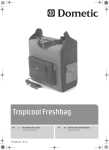
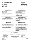
RECORD THIS INFORMATION FOR FUTURE REFERENCE: FRTA Model Number FRTA Serial Number Hardware Model Number Hardware Serial Number Date Purchased Retailer / Qualified Installer USA SERVICE OFFICE Dometic Corporation 2320 Industrial Parkway Elkhart, IN 46516 CANADA Dometic Corporation 46 Zatonski, Unit 3 Brantford, ON N3T 5L8 CANADA For Service Center Or Dealer Locations Please Visit: POWER PATIO AWNING HARDWARE 8952(X)(X)1.4(X)0(#) BASEMENT 8952(X)(X)2.4(X)0(#) STANDARD FRTA FABRIC ROLLER TUBE ASSEMBLY 91(X)(XX)(YY).(XXX)(#) 91(X)(XX)(YY).(XXX)(#)L www.eDometic.com OR www.RV.com HARDWARE OPERATING INSTRUCTIONS REVISION Form No. 3312736.048 02/13 (Replaces 3312736.030) (French 3312739.042) ©2013 Dometic Corporation LaGrange, IN 46761 3312736.048 8952(X)(X)(X).4(X)0(#) FRTA 91(X)(XX)(YY).(XXX)(#) 91(X)(XX)(YY).(XXX)(#)L Read these instructions carefully. These instructions MUST stay with this product. INTRODUCTION This awning (hereinafter referred to as “awning,” or “product”) is designed and intended for use on RVs with straight sides. For curved sides, please see the separate Hardware List in the Dealer Service Manual for the appropriate model. Use these instructions to ensure correct operation of product. Dometic Corporation reserves the right to modify appearances and specifications without notice. TABLE OF CONTENTS INTRODUCTION.....................................................................................................................................................................2 DOCUMENT SYMBOLS.........................................................................................................................................................2 IMPORTANT SAFETY INSTRUCTIONS.................................................................................................................................3 A. Recognize Safety Information....................................................................................................................................3 B. Understand Signal Words...........................................................................................................................................3 C. Supplemental Directives.............................................................................................................................................3 D. General Safety Messages..........................................................................................................................................3 PROCEDURE..........................................................................................................................................................................4 A. Open Awning..............................................................................................................................................................4 B. LED Light Strip (If Equipped)......................................................................................................................................4 C. Adjust Awning Pitch (Optional)...................................................................................................................................4 D. Prepare Awning To Shed Water..................................................................................................................................5 E. Close Awning..............................................................................................................................................................6 F. Prepare Awning For Travel.........................................................................................................................................6 CLOSE AWNING MANUALLY (POWER FAILURE)................................................................................................................7 A. Auxiliary Power Method..............................................................................................................................................7 B. Pull Strap Method.......................................................................................................................................................8 GENERAL CARE AND USE....................................................................................................................................................8 A.Precautions.................................................................................................................................................................8 B. Hardware Maintenance..............................................................................................................................................9 C. Fabric Maintenance....................................................................................................................................................9 D. When To Get More Help.............................................................................................................................................9 DOCUMENT SYMBOLS Indicates additional information that is NOT related to physical injury. Indicates step-by-step instructions. 2 IMPORTANT SAFETY INSTRUCTIONS D. General Safety Messages This manual has safety information and instructions to help you eliminate or reduce the risk of accidents and injuries. Failure to obey the following warnings could result in death or serious injury: A. Recognize Safety Information This is the safety alert symbol. It is used to alert you to potential physical injury hazards. Obey all safety messages that follow this symbol to avoid possible injury or death. ●● This product MUST be [installed / serviced] by a qualified service technician. ●● Do NOT modify this product in any way. Modification can be extremely hazardous. B. Understand Signal Words ●● Frequently examine product for imbalance (uneven fit / sagging / loose parts); and signs of wear or damage to wiring (if applicable) and other critical parts. Do NOT use product if adjustments or repairs are necessary. A signal word will identify safety messages and property damage messages, and will indicate the degree or level of hazard seriousness. indicates a hazardous situation that, if NOT avoided, could result in death or serious injury. Critical parts may include awning fabric, cables, arm assemblies, etc. indicates a hazardous situation that, if NOT avoided, could result in minor or moderate injury. ●● Disconnect product from power supply (if applicable), and do NOT operate product when maintenance (such as window cleaning) is being carried out in the vicinity. is used to address practices NOT related to physical injury. ●● Do NOT allow anyone (including children) with reduced physical, sensory or mental capabilities, or lack of experience and knowledge to use this product, unless they have been given supervision or instruction (concerning use of this product) by a person responsible for their safety. C. Supplemental Directives Read and follow all safety information and instructions to avoid possible injury or death. Read and understand these instructions before [installing / using / servicing / performing maintenance] on this product. ●● Do NOT allow children to play with product or with fixed controls (if applicable). Keep remote controls (if applicable) away from children. Incorrect [installation / operation / servicing / maintaining] of this product can lead to serious injury. Follow all instructions. ●● IMPACT OR CRUSH HAZARD. NEVER leave an open awning unattended. Keep awning stowed (closed) when snow, heavy rain, wind, and severe weather conditions are expected. The installation MUST comply with all applicable local and national codes, including the latest edition of the following standards: ●● IMPACT OR CRUSH HAZARD. Do NOT allow water to pool, snow to accumulate, or heavy debris on awning fabric. Do NOT hang or place anything on awning. The awning will become unstable, and could bend or collapse. U.S.A. ●● ANSI/NFPA70, National Electrical Code (NEC) ●● FIRE HAZARD. Keep sources of heat and fire (barbecue grills, portable heater, etc.) away from awning. ●● ANSI/NFPA 1192, Recreational Vehicles Code CANADA ●● CSA C22.1, Parts l & ll, Canadian Electrical Code PINCH HAZARD. Maintain a horizontal distance of at least 16″ between fully open awning and any permanent object. Failure to obey this caution could result in injury. ●● CSA Z240 RV Series, Recreational Vehicles Do NOT face awning toward permanent objects that may interfere with awning operation. 3 PROCEDURE A. Open Awning FIG. 2 1. PINCH HAZARD. Maintain a horizontal distance of at least 16″ between fully open awning and any permanent object. Failure to obey this caution could result in injury. Wrong Position. Awning Is OverExtended With Valance Rope Behind Roller Tube. Press and hold toggle to extend (ON) position on (fixed/wired) remote awning switch until awning is fully extended. See (FIG. 1). Awning will automatically stop when button is released no matter how far awning is extended/retracted. FIG. 1 ON Stop Correct Position. Awning Is Extended Correctly With Valance Rope At Top Of Roller Tube. ON Switch Appearance May Vary B. LED Light Strip (If Equipped) 2. IMPACT OR CRUSH HAZARD. Do NOT allow awning to remain in over-extended position as this could trap heavy debris, or could cause water to pool or snow to accumulate on awning fabric. This weight will cause awning to become unstable, and bend or collapse. Failure to obey this warning could result in death or serious injury. LED switch operation and appearance may vary depending on application. 1. Turn LED switch to ON position to illuminate LED light strip. LED light strip may be used while awning is open or closed. 2. Turn LED switch to OFF position when LED light strip is not in use. Verify valance is in correct position, and adjust if necessary. If awning is over-extended, press toggle down (retract) briefly on (fixed/wired) remote awning switch until valance is in correct position. See (FIG. 1) & (FIG. 2). C. Adjust Awning Pitch (Optional) The FRTA (fabric roller tube assembly) will be lower than RV’s awning rail when hardware is fully extended. This pitch (slope) will help accommodate water runoff. If a steeper pitch is desired, the FRTA must be lowered. To lower FRTA: 1. With awning fully extended, loosen adjustable knob on adjustable pitch arm assembly (bottom arm). See (FIG. 3). 4 PROCEDURE FIG. 3 3. While holding top arm assembly in place, tighten adjustable knob to set pitch (slope). See (FIG. 3) & (FIG. 4). Front Channel Adjustable Knob 4. IMPACT OR CRUSH HAZARD. ALWAYS place one side of hardware in water shed position when adjusting awning pitch (slope). Otherwise, water could pool on awning fabric. Failure to obey this warning could result in death or serious injury. Adjustable Pitch Arm Assembly Repeat steps (1) through (3) for opposite side. Make sure the top arm assembly that’s farthest from entry door is lowered more than the other. See subsection, “D. Prepare Awning To Shed Water” on page (5). D. Prepare Awning To Shed Water 2. PINCH HAZARD. Keep CLEAR of openings around adjustable pitch arm assembly while adjusting awning pitch (slope). Adjustable pitch arm assembly (bottom arm) will telescope. Failure to obey this caution could result in injury. IMPACT OR CRUSH HAZARD. Do NOT allow water to pool or snow to accumulate on awning fabric. The awning will become unstable, and could bend or collapse. Whenever heavy rain or snow is expected, place awning in stowed (closed) position. Failure to obey this warning could result in death or serious injury. Do NOT allow corner of entry door to contact awning fabric. Otherwise, premature wear or tearing of awning fabric could occur. Lowering one arm assembly into water shed position (to create a slope from other arm assembly) will allow water run-off during light rain. 1. With awning fully extended, verify top arm assembly nearest entry door is fully extended, and that adjustable knob is tightened. See (FIG. 3). Pull top arm assembly down to lower FRTA to desired height. See (FIG. 4). FIG. 4 2. IMPACT OR CRUSH HAZARD. NEVER disengage adjustable knob with water pooled or snow accumulated on awning fabric. This will cause the awning to collapse. Failure to obey this warning could result in death or serious injury. Top Arm Assembly Do NOT allow corner of entry door to contact awning fabric. Otherwise, premature wear or tearing of awning fabric could occur. Loosen adjustable knob on adjustable pitch arm assembly (bottom arm) that’s farthest from entry door. See (FIG. 3). Lowering the arm assembly that’s nearest entry door could allow door to contact fabric. If awning pitch was previously adjusted lower, raising arm nearest entry door will provide more fabric clearance. Adjustable Pitch Arm Assembly 5 PROCEDURE 3. PINCH HAZARD. Keep CLEAR of openings around adjustable pitch arm assembly while adjusting awning pitch (slope). Adjustable pitch arm assembly (bottom arm) will telescope. Failure to obey this caution could result in injury. FIG. 6 Top Arm Assembly Pull top arm assembly (farthest from entry door) down until awning slopes approximately 10°, or 9″ minimum from other arm assembly. See (FIG. 4) & (FIG. 5). Pinch Points Pinch Point This slope requirement is in addition to the slope from RV’s awning rail. FIG. 5 10° Slope (Or 9″ Minimum) Back Channel Awning Rail Front Channel Adjustable Arm Assembly Pinch Points Arm Assembly F. 4. While holding top arm assembly in place, tighten adjustable knob to set in place. See (FIG. 3) & (FIG. 4). E. Prepare Awning For Travel 1. IMPACT OR CRUSH HAZARD. Verify ignition interlock is working correctly before traveling with RV. If awning responds to switch with ignition in ON position, accidental operation during transit could occur. The awning MUST be disabled and serviced by a qualified service technician. Failure to obey this warning could result in death or serious injury. Close Awning 1. Loosen adjustable knobs to allow awning to reset to original position. Then lightly tighten knobs on both arm assemblies to help ensure rattle-free travel. See (FIG. 3). Pull top arm assembly down to verify knob is NOT too tight. Adjustable pitch arm assembly MUST still slide as normal. See (FIG. 4). 2. PINCH HAZARD. Keep CLEAR of arm assemblies while closing awning. Arm assemblies will [fold / close] against back channel. Failure to obey this warning could result in death or serious injury. Press and hold toggle to retract (ON) position on (fixed/wired) remote awning switch until awning is fully closed. See (FIG. 1) & (FIG. 6). Awning will automatically stop when button is released no matter how far awning is extended/retracted. 6 With awning fully closed, Test ignition interlock system: a. With vehicle ignition in ON position, attempt to open awning. b. If awning does NOT respond (remains closed), the ignition interlock is functioning. Skip to step (3). c. If awning responds to switch (awning opens), there is a problem with the ignition interlock system. Proceed to step (2). 2. Disable awning for travel to service center: a. Close awning and remove fuse for power source to awning. b. Retest ignition interlock. See step (1). c. If awning does NOT respond (remains closed), the awning is now disabled. Skip to step (f). PROCEDURE d. If awning still operates, pull motor connector from hardware connector to disconnect motor wiring. See (FIG. 7). f. Have awning repaired by a qualified service technician. 3. Turn LED light strip (if equipped) OFF before travel. See “B. LED Light Strip (If Equipped)” on page (4). 4. Verify awning is secure for travel. The motor connector may be hard to reach when awning is closed. Pull wiring at RH top casting until wires disengage. Look for loose parts, and any sign of instability. e. Repeat step (1) to verify motor is disabled. CLOSE AWNING MANUALLY (POWER FAILURE) In case of power failure, it may be necessary to close awning manually. There are two methods to close awning manually: Perform procedure under, “A. Auxiliary Power Method” on page (7) first. If this fails, perform procedure under, “B. Pull Strap Method” on page (8). FIG. 7 Rule out simple causes for power failure (RV disconnected from power, blown fuse, low/discharged battery, ignition interlock, etc.) before attempting to close awning manually. After awning is closed manually, it will require service by a qualified service technician. Motor Connector Hardware Connector The LED light strip (if equipped) is on a separate circuit from awning motor. If LED lights work, but awning motor does not, check awning motor’s fuse (at fuse panel or converter) before closing awning manually. 4. Connect 16 Gauge (minimum) wire leads (user supplied) to motor connector, and tape in place (with electrical tape). A. Auxiliary Power Method Do NOT connect to hardware connector. When awning is in open position and 12 Vdc power has been lost, the awning may be closed by supplying auxiliary power (from external source) to awning motor. Match wire lead colors to motor wire colors (black to black, red to red). 5. Disconnect power IMMEDIATELY after awning retracts. Otherwise, damage to awning motor could occur. A 12 Vdc automobile battery may be used as an external power source. 1. Loosen adjustable knobs to allow awning to reset to original position. Then lightly tighten knobs on both arm assemblies to help ensure rattle-free travel. See (FIG. 3). Connect other end of wire leads to the 12 Vdc external power source, until awning retracts to its closed position: a. Connect red wire to positive (+) terminal. 2. ELECTRICAL SHOCK HAZARD. Disconnect power from product before accessing wiring connections. There may be issues mimicking a power failure with electric current still present, or power may return unexpectedly. Failure to obey this warning could result in death or serious injury. The lead wire connected to positive (+) terminal MUST have a (3 A) in-line fuse installed. b. Connect black wire to negative (-) terminal. c. Disconnect wire leads from power source once awning fully retracts. The awning will extend if wire leads are reversed (reversed polarity). Disconnect 120 Vac power from RV, and 12 Vdc power to awning. 3. Unplug motor connector from hardware connector (located in upper part of RH arm assembly). See (FIG. 7). 7 6. If awning does not move (after confirming connections and charge on external power source), the motor may be defective. Proceed to subsection, “B. Pull Strap Method” on page (8) for alternative method. CLOSE AWNING MANUALLY (POWER FAILURE) B. Pull Strap Method 4. IMPACT OR PINCH HAZARD. Hold pull strap firmly before removing screw(s) at top casting. The fabric roller tube is under spring tension, which will attempt to close the awning quickly and unexpectedly. Failure to obey this warning could result in death or serious injury. Use this procedure if prior method failed to close awning. This procedure requires a 5/32″ hex key, and help from at least one other person. 1. Make sure adjustable knobs are only lightly tightened on both arm assemblies. See (FIG. 3). 2. Make sure motor connector from hardware connector (located in upper part of RH arm assembly is unplugged. See (FIG. 7). 3. Insert pull strap (provided) into utility slot of FRTA, and slide to center (of FRTA). See (FIG. 8). While one person grasps pull strap firmly, remove the (2) screws at top and back of RH top casting. Save for reinstallation later. See (FIG. 8). 5. PINCH HAZARD. Keep CLEAR of arm assemblies while closing awning. Arm assemblies will [fold / close] against back channel. Failure to obey this warning could result in death or serious injury. FIG. 8 Move pull strap diagonally (to left or right) as awning rolls up. Otherwise, awning fabric may crease or form a bulge, and could permanently stretch fabric. Carefully and slowly allow awning to roll up (close). 6. IMPACT OR CRUSH HAZARD. Reinstall screw(s) at top casting BEFORE transporting RV. Otherwise, awning could extend quickly and unexpectedly during transit. Failure to obey this warning could result in death or serious injury. (2) Screws In Top Casting Align holes in RH top casting (where screws were removed), and reinstall the (2) screws to secure awning for travel. Do NOT reattach wiring. Awning will require service by a qualified service technician. GENERAL CARE AND USE A. Precautions ●● NEVER close awning (for storage) when wet. The combination of moisture and dirt could result in mildew, discoloration, and stains. Failure to obey the following notices could damage product or property: If it is necessary to roll up awning (temporarily) while it’s wet, make sure you roll it out and let it dry (as soon as conditions allow) before rolling it up again. ●● Do NOT use insecticides or other sprays near awning fabric. These could cause stains, and could adversely affect fabric’s ability to repel water. ●● Do NOT allow dirt, leaves, or other debris to accumulate on awning, which could cause abrasion and stains. Mildew could grow on dirt and organic debris causing permanent discoloration, stains, and odors to awning fabric. ●● Do NOT expose awning to adverse environmental conditions, corrosive agents, or other harmful conditions. ●● Do NOT allow corner of entry door to contact awning fabric. Otherwise, premature wear or tearing of awning fabric could occur. 8 GENERAL CARE AND USE B. Hardware Maintenance 2. To repair a pinhole, or if a spot of coating flakes off from top layer of vinyl fabric: a. Apply a very small dab of VLP (Vinyl Liquid Patch) on tip of cotton swab. 1. Do NOT use strong chemicals or abrasives to clean parts, as their protective surfaces will be damaged. VLP is available from Dometic Corporation. Reference part number 3314216.000 when ordering. Clean awning hardware (as needed) with a mild surface cleaner. 2. Do NOT use silicone sprays near labels. Otherwise, the label’s adhesive bond to product surfaces could weaken. b. Gently roll cotton swab around pinhole. The VLP will melt the coating (on fabric) and that will quickly fill in pinhole and blend with all colored vinyls. Apply silicone spray lubricant as needed to keep the fabric roller tube assembly’s moving parts operating smoothly. 3. Lubricate all sliding surfaces of arm assemblies with silicone spray as needed. c. NEVER close (roll up) awning when vinyl liquid patch is wet. Otherwise, damage to other parts of awning fabric (melting through layers) will occur. Allow VLP to dry thoroughly before stowing (rolling up) awning. C. Fabric Maintenance Vinyl fabric offers the advantage of durability and water resistance. D. When To Get More Help Wrinkling is a normal characteristic of vinyl. Wrinkling may be more noticeable when retracted, and after prolonged periods of stowage (rolled up). Leave awning open during warm weather to minimize the wrinkling over a period of time. If malfunctions occur (that cannot be corrected by reviewing these instructions), contact a qualified service technician. A slight “travel line” may appear where door roller (if installed) contacts awning fabric. This is considered normal and does NOT affect the integrity of awning fabric. 1. To clean: a. Mix 1/4 cup dish soap and 1/4 cup bleach to 5 gallons of fresh water to use as cleaning solution. b. Do NOT use abrasive or corrosive cleaners, mildew removers, or hard bristle brushes on awning fabric. Liberally drench open awning fabric with cleaning solution. c. Close awning, let it soak for 5 minutes, then open awning again. d. Remove solution COMPLETELY from awning fabric. Bleach will degrade awning fabric if NOT completely rinsed off. Thoroughly hose off top and bottom of fabric with clean water. Repeat as necessary to completely remove solution. e. NEVER close awning (for storage) when wet. The combination of moisture and dirt could result in mildew, discoloration, and stains. Allow awning to dry thoroughly before stowing (rolling up). 9