1
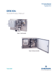
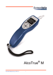
Operations & Service Manual
DOPSM2091X012
July 2015
TESCOM 50-4X Series
Safety, Installation & Start-Up Procedures
Do not attempt to select, install, use
or maintain this product until you have
read and fully understood this manual.
50-4X Series
Table of Contents
DOPSM2091X012
July 2015
Contents
Section 1: Symbols. . . . . . . . . . . . . . . . . . . . . . . . . . . . . . . . . . . . . . . . . . . . . . . . . . . . . . . . . . . .
4
Section 2: S
afety, Installation and Operations Precautions. . . . . . . . .
2.1
2.2
4
Installation. . . . . . . . . . . . . . . . . . . . . . . . . . . . . . . . . . . . . . . . . . . . . . . . . . . . . . . . . . . 6
Repair Service . . . . . . . . . . . . . . . . . . . . . . . . . . . . . . . . . . . . . . . . . . . . . . . . . . . . . . . . 6
Section 3: Installation . . . . . . . . . . . . . . . . . . . . . . . . . . . . . . . . . . . . . . . . . . . . . . . . . . . . . . . .
3.1
3.2
3.3
3.4
Introduction. . . . . . . . . . . . . . . . . . . . . . . . . . . . . . . . . . . . . . . . . . . . . . . . . . . . . . . . . .
Specifications. . . . . . . . . . . . . . . . . . . . . . . . . . . . . . . . . . . . . . . . . . . . . . . . . . . . . . . . .
Installation Diagram. . . . . . . . . . . . . . . . . . . . . . . . . . . . . . . . . . . . . . . . . . . . . . . . . . .
Installation. . . . . . . . . . . . . . . . . . . . . . . . . . . . . . . . . . . . . . . . . . . . . . . . . . . . . . . . . . .
7
7
7
8
8
Section 4: Start-up Procedures. . . . . . . . . . . . . . . . . . . . . . . . . . . . . . . . . . . . . . . . . . . . . .
4.1
4.2
Table of Contents
10
Manual Override Start-up Procedure. . . . . . . . . . . . . . . . . . . . . . . . . . . . . . . . . . . . . . 10
Non-Manual Override Start-up Procedure. . . . . . . . . . . . . . . . . . . . . . . . . . . . . . . . . . . . . 11
3
Section 1: Symbols
July 2015
50-4X Series
DOPSM2091X012
Section 1: Symbols
WARNING
aragraphs highlighted by the CAUTION icon contain information that must be followed to
P
maintain a safe and successful operating environment.
CAUTION
aragraphs highlighted by the WARNING icon contain information about practices or
P
circumstances that can lead to personal injury or death, property damage or economic loss.
Section 2: Safety, Installation and
Operations Precautions
WARNING
Do not attempt to select, install, use, or maintain this regulator, valve, or accessory
until you have read and fully understand these instructions.
Be sure this information reaches the operator and stays with the product
after installation.
Do not permit untrained persons to install, use, or maintain this regulator, valve,
or accessory.
Improper selection, improper installation, improper maintenance, misuse, or abuse
of regulators, valves, or related accessories can cause death, serious injury, and/or
property damage.
Oxygen service requires special expertise and knowledge of system design and
material compatibility in order to minimize the potential for death, serious injury, and/
or property damage.
Possible consequences include but are not limited to:
• High velocity fluid (gas or liquid) discharge
• Parts ejected at high speed
• Contact with fluids that may be hot, cold, toxic or otherwise injurious
• Explosion or burning of the fluid
• Lines/hoses whipping dangerously
• Damage or destruction to other components or equipment in the system
4
Section 1: Symbols
50-4X Series
Section 2: Safety, Installation and Operations Precautions
DOPSM2091X012
July 2015
CAUTION
Safety Precautions
1. Inspect the regulator, valve, and accessories before each use.
2. Never connect regulators, valves, or accessories to a supply source having a pressure
greater than the maximum rated pressure of the regulator, valve, or accessory.
3. Refer to product label (model specific) for maximum inlet pressures. If this rated
pressure cannot be found, contact your local TESCOM representative for the rated
pressure prior to installation and use. Verify the designed pressure rating of all
equipment (e.g., supply lines, fittings, connections, filters, valves, gauges, etc.) in your
system. All must be capable of handling the supply and operating pressure.
4. Clearly establish flow direction of the fluid before installation of regulators, valves,
and accessories. It is the responsibility of the user to install the equipment in the
correct direction.
5. Remove pressure from the system before tightening fittings, gauges or components.
6. Never turn regulator or valve body. Instead hold regulator or valve body and turn
fitting nut.
7. If a regulator or valve leaks or malfunctions, take it out of service immediately.
8. Do not modify equipment or add attachments not approved by the manufacturer.
9. Apply pressure to the system gradually, avoiding a sudden surge of fluid or pressure
shock to the equipment in the system.
10. Regulators are not shut-off devices. Install a pressure relief device downstream of the
regulator to protect the process equipment from overpressure conditions. Shut off the
supply pressure when the regulator is not in use.
11. Periodic inspection and scheduled maintenance of your equipment is required for
continued safe operation.
12. The frequency of servicing is the responsibility of the user based on the application.
Positive seal/tied diaphragm regulators require the downstream pressure vented before
turning the hand knob counterclockwise to reduce the outlet pressure. Damage may
occur to the regulator if this procedure is not followed.
13. Never allow problems or lack of maintenance to go unreported.
14. Read and follow precautions on compressed gas cylinder labels.
15. It is important that you analyze all aspects of your application and review all available
information concerning the product or system. Obtain, read, and understand the
Material Safety Data Sheet (MSDS) for each fluid used in your system.
16. Never use materials for regulators, valves, or accessories that are not compatible with
the fluids being used.
17. Users must test components for material compatibility with the system operating
conditions prior to use in the system.
18. Vent fluids to a safe environment, and in an area away from employees. Be sure
that venting and disposal methods are in accordance with Federal, State, and
Local requirements. Locate and construct vent lines to prevent condensation or
gas accumulation. Make sure the vent outlet is not obstructed by rain, snow, ice,
vegetation, insects, birds, etc. Do not interconnect vent lines; use separate lines if more
than one vent is needed.
Section 2: Safety, Installation and Operations Precautions
5
Section 2: Safety, Installation and Operations Precautions
July 2015
50-4X Series
DOPSM2091X012
19. Do not locate regulators, valves, or accessories controlling flammable fluids near open
flames or any other source of ignition.
20. Some fluids when burning do not exhibit a visible flame. Use extreme caution when
inspecting and/or servicing systems using flammable fluids to avoid death or serious
injury to employees. Provide a device to warn employees of these dangerous conditions.
21. Many gases can cause suffocation. Make certain the area is well ventilated. Provide a
device to warn employees of lack of Oxygen.
22. Never use oil or grease on these regulators, valves, or accessories. Oil and grease are
easily ignited and may combine violently with some fluids under pressure.
23. Have emergency equipment in the area if toxic or flammable fluids are used.
24. Upstream filters are recommended for use with all fluids.
25. Do not bleed system by loosening fittings.
26. Prevent icing of the equipment by removing excess moisture from the gas.
27. Always use proper thread lubricants and sealants on tapered pipe threads.
2.1Installation
CAUTION
Do not open packaging until ready for installation or in a clean environment. Product
is cleaned in accordance with CGA 4.1 and ASTM G93, Verification Type 1, Test 1 and
Test 2. With periodic verification of cleaning process to MIL-STD-1330D.
WARNING
Make sure that the components and materials used in the fluid handling system are
compatible with the fluid and have the proper pressure rating. Failure to do so can
result in death, serious injury, and/or property damage.
Inspect the regulator, valve, and accessories for physical damage and contamination. Do not
connect the regulator, valve, or accessory if you detect oil, grease, or damaged parts. If the
regulator, valve, or accessory is damaged, contact your local TESCOM representative to have
the regulator cleaned or repaired.
2.2
Repair Service
If a regulator or valve leaks or malfunctions, take it out of service immediately. You must have
instructions before doing any maintenance. Do not make any repairs you do not understand.
Have qualified personnel make repairs. Return any equipment in need of service to your
equipment supplier for evaluation and prompt service. Equipment is restored to the original
factory performance specifications, if repairable. There are flat fee repair charges for each
standard model. The original equipment warranty applies after a complete overhaul.
6
Section 2: Safety, Installation and Operations Precautions
50-4X Series
Section 3: Installation
DOPSM2091X012
July 2015
CAUTION
Proper Component Selection
1. Consider the total system design when selecting a component for use in a system.
2. The user is responsible for assuring all safety and warning requirements of the
application are met through his/her own analysis and testing.
3. TESCOM may suggest material for use with specific media upon request. Suggestions
are based on technical compatibility resources through associations and manufacturers.
TESCOM does NOT guarantee materials to be compatible with specific media -- THIS IS
THE RESPONSIBILITY OF THE USER!
4. Component function, adequate ratings, proper installation, operation, and
maintenance are the responsibilities of the system user.
WARNING
Do not modify equipment or add attachments not approved by the manufacturer.
Failure to do so can result in death, serious injury, and/or property damage.
ASSEMBLY/INSTALLATION DRAWINGS & BILLS OF MATERIAL drawings and parts lists for your product may
be obtained by contacting TESCOM. TESCOM will provide these by email, fax or mail. Your local TESCOM
representative can provide additional assistance. Be sure to have your complete model number ready.
Section 3: Installation
3.1Introduction
50-4X Series pressure reducing regulators are specifically designed for extended life operation
in high pressure hydraulic applications. The 50-4X Series is designed with an integrated bypass
valve which controls large variations in flow rates at pressures up to 15,000 psig / 1034 bar.
Applications include hydraulic power units for production, wellhead control panels (WHCP)
and intervention work over control systems (IWOCS), where start-up requires high flow rates at
large differentials and operate at high pressures with precise control.
3.2Specifications
Maximum Inlet Pressure:
10,000 & 15,000 psig / 690 & 1034 bar
Maximum Outlet Pressure:
5500-15,000, 3000-10,000, 3000-6000, 3000-4000 psig
380-1034, 207-690, 207-414, 207-275 bar
Operating Temperature:
-15°F to 165°F / -26°C to 73°C
Flow Capacity:
Cv = 0.12 (Control Regulator)
Cv = 1.9 (Integrated Bypass)
Weight:
Approximately 14 lbs / 6.4 kg
Section 3: Installation
7
Section 3: Installation
50-4X Series
July 2015
3.3
DOPSM2091X012
Installation Diagram
Letter call-outs are referenced in the Installation and Start-Up Procedures section of
this manual.
50-4X
A
SERIES
F
15,000
B
C
G
6000
psig
psig
INLET
OUTLET
VALVE
VALVE
E
VENT LINE
D
3.4Installation
WARNING
Failure to follow these instructions or to properly install and maintain this equipment
could result in an explosion, fire and/or chemical contamination causing property
damage and personal injury or death.
TESCOM regulators must be installed, operated, and maintained in accordance with
federal, state, and local codes, rules and regulations.
If the regulator vents gas or a leak develops in the system, service to the unit may be
required. Failure to correct trouble could result in a hazardous condition.
Installation, operation, and maintenance procedures performed by unqualified
personnel may result in improper adjustment and unsafe operation. Either condition
may result in equipment damage or personal injury. Call qualified personnel when
installing, operating, and maintaining the 50-4X Series regulator.
8
Section 3: Installation
50-4X Series
Section 3: Installation
DOPSM2091X012
July 2015
WARNING
Personal injury, equipment damage, or leakage due to escaping fluid may result
if needle valves are used to isolate the pressure reducing regulator. It is strongly
recommended that block valves be used to properly isolate the regulator from system.
Confirm with gauges that there is zero pressure in the system prior to installation:
Note: Refer to the Installation Diagram for additional information.
1. Confirm both the inlet (A) and outlet (C) block and bleed valves are closed prior
to installation.
2. Install the regulator with inlet port connected to the supply or inlet piping of the system
and connect the outlet port to the downstream piping in the system.
3. Connect the vent port of the regulator to the vent line (D) (return line to reservoir).
Note: Skip Step 4 if the regulator does not have the manual override external
hex (E) option.
4. For units with the manual override external hex remove cap (E).
a. Rotate external hex clockwise until a metal stop occurs (hand tight)
5. Confirm all pipe fittings are torqued to manufacturer’s recommended rating.
WARNING
Personal injury, equipment damage, or leakage due to escaping accumulated fluid or
bursting of pressure-containing parts may result if this regulator is:
• Over-pressured
• Used with incompatible process fluid
• Installed where service conditions could exceed the limits given in the
specifications section and on the appropriate nameplate
• Where conditions exceed any ratings of adjacent piping or piping connections.
To avoid such injury or damage, provide pressure-relieving or pressure-limiting
devices to prevent service conditions from exceeding those limits
Section 3: Installation
9
Section 4: Start-up Procedures
50-4X Series
July 2015
DOPSM2091X012
Section 4: Start-up Procedures
4.1
Manual Override Start-up Procedure
The manual override option allows operators to manually turn off the bypass valve in the
event that their final control pressure would need to be below the bypass valve setpoint.
WARNING
To avoid possible personal injury, equipment damage, or leakage due to escaping fluid,
make certain the regulator is installed as instructed in the Installation section. Pressure
gauges must always be used to monitor downstream pressure during Start-up.
Note: For airload units follow the same process except instead of adjusting the handknob
adjust the pressure on the airloader appropriately.
Note: Refer to the Installation Diagram for additional information. Page 8.
1. Begin with the manual override external hex under the cap (E) fully engaged.
2. Rotate regulator hand knob (B) counterclockwise until it stops turning. This will change
the regulator’s setpoint to 0 psi / 0 bar which will effectively close the regulator.
3. Leave the inlet (A) and outlet (C) block and bleed valves surrounding the regulator
closed and pressurize the supply side or inlet side of the system.
4. Slowly open the inlet block valve (A) to apply pressure to the inlet of the 50-4X regulator (B).
5. Verify the regulator’s inlet pressure (F).
6. Verify the regulator’s outlet pressure (G) to determine if there is any leakage. If there is
any leakage, remove regulator for inspection and repair. If no leakage occurs move on to
Step 7.
7. Check the vent line (D) for any sign of leakage. If leakage occurs remove regulator for
inspection and repair. If no leakage occurs move on to step 8.
8. Slowly adjust the regulator hand knob (B) clockwise to increase the outlet pressure (G)
until the pressure is above the bypass valve setpoint and verify pressure is stable (not
increasing or decreasing).
9. Slowly open the bypass valve by adjusting the manual override hex (E)
counterclockwise (CCW) until a metal stop occurs.
10. Verify outlet pressure (G). It should not change.
11. Fully open outlet valve (C) to fill downstream volume.
12. Verify and record flow rate and pressure over time.
13. Adjust the outlet pressure to the desired pressure setting above the bypass
valve setpoint.
Note: If the desired control pressure is below the bypass valve setpoint, the manual
override must be closed using the external hex under the cap (E).
14. Pressure will be vented off as the pressure setting is adjusted to a lower setpoint.
10
Section 4: Start-up Procedures
50-4X Series
Section 4: Start-up Procedures
DOPSM2091X012
4.2
July 2015
Non-Manual Override Start-up Procedure
WARNING
To avoid possible personal injury, equipment damage, or leakage due to escaping fluid,
make certain the regulator is installed as instructed in the Installation section. Pressure
gauges must always be used to monitor downstream pressure during Start-up.
Note: For airload units follow the same process except instead of adjusting the handknob
adjust the pressure on the airloader appropriately.
Note: Refer to the Installation Diagram for additional information. Page 8.
1. Prior to opening the supply or inlet block valve (A), rotate the hand knob of the
regulator (B) clockwise until it stops turning. This will verify the regulator (B) is set at its
maximum setpoint.
2. Pressurize the system upstream of the closed inlet block and bleed valve (A).
3. Slowly open the inlet block valve (A) to apply pressure up to the inlet of the 50-4X
regulator (B).
4. Verify inlet pressure (F).
5. Verify the regulator’s outlet pressure (G) is stable and not increasing at its maximum
setpoint to determine if there is any leakage. If there is any leakage, remove regulator
for inspection and repair. If no leakage occurs, move on to Step 6.
6. Check the vent line (D) for any sign of leakage. If leakage occurs remove regulator for
inspection and repair. If no leakage occurs move on to Step 7.
7. Turn the hand knob of the regulator (B) counterclockwise to decrease outlet pressure
to below the desired outlet pressure setting. Pressure will be vented off through the
vent return line (D) as the pressure setting is adjusted to a lower setpoint but it must be
above the bypass valve setpoint.
8. Turn the hand knob clockwise to increase outlet pressure to the desired outlet pressure
setting that is above the bypass valve setpoint.
9. Verify pressure is stable (G) (not increasing or decreasing).
10. Fully open outlet valve (C) to fill downstream volume.
11. Verify and record flow rate and pressure over time.
Note: If the desired pressure is below the bypass setpoint, the regulator will need the
manual override option.
Section 4: Start-up Procedures
11
Emerson Process Management
Regulator Technologies Inc.
TESCOM
AMERICAS
12616 Industrial Blvd.
Elk River, MN 55330 USA
T +1 800 447 1250
+1 763 241 3238
F +1 763 241 3224
[email protected]
www.tescom.com
ASIA PACIFIC
3/F, Building #2 No. 1277
Xin Jin Qiao Road Jinqiao E.P.Z.
Pudong Shanghai 201206 China
T +86 21 2892 9970
F +86 21 2892 9001
[email protected]
www.tescom.com
EUROPE
An der Trave 23-25
23923 Selmsdorf, Germany
T +49 (0) 3 88 23/31-287
F +49 (0) 3 88 23/31-140
[email protected]
www.tescom-europe.com
MIDDLE EAST & AFRICA
PO Box 17033 Jebel Ali Free Zone-South
(Zone 2)
Dubai, UAE
T +971 4 811 8443
F +971 4 886 5465
[email protected]
www.tescom.com
Brandon House
23-25 Brandon Street
Hamilton ML3 6DA
South Lanarkshire, UK
T +44 1698 424 254
F +44 1698 459 299
[email protected]
www.tescom.com
DOPSM2091X012 ©TESCOM Corporation, 2015; All Rights Reserved.
TESCOM is a business unit of Emerson Process Management Regulator
Technologies, Inc. Trademarks are property of divisions of Emerson
Process Management.
The contents of this publication are presented for information purposes
only, and while effort has been made to ensure their accuracy, they are not
to be construed as warranties or guarantees, express or implied, regarding
the products or services described herein or their use or applicability.
All sales are governed by our terms and conditions, which are available
on request. We reserve the right to modify or improve the designs or
specifications of our products at any time without notice.