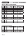
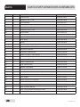
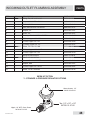
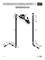
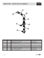
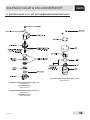
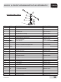
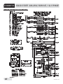
1
TEMPSTAR SERIES
UPRIGHT DOOR
DISHMACHINES
INSTALLATION, OPERATION,
AND SERVICE MANUAL
FOR JACKSON MODEL(S):
TEMPSTAR
TEMPSTAR LT
TEMPSTAR NB
TEMPSTAR
WITH VENTLESS
AND ENERGY RECOVERY
STEAM HEATED MODELS:
TEMPSTAR S
TEMPSTAR/LT/NB/ VENTLESS/S Technical Manual • Rev S • P/N 7610-003-61-42 • Issued: 11-11-2008 • Revised: 11-30-2015
MANUFACTURER'S WARRANTY
ONE YEAR LIMITED PARTS AND LABOR WARRANTY
ALL NEW JACKSON DISHWASHERS ARE WARRANTED TO THE ORIGINAL PURCHASER TO BE FREE FROM DEFECTS IN
MATERIAL OR WORKMANSHIP, UNDER NORMAL USE AND OPERATION FOR A PERIOD OF (1) ONE YEAR FROM DATE OF
PURCHASE, BUT IN NO EVENT TO EXCEED (18) EIGHTEEN MONTHS FROM DATE OF SHIPMENT FROM THE FACTORY.
Jackson WWS agrees under this warranty to repair or replace, at its discretion, any original part which fails under normal use
due to faulty material or workmanship during the warranty period, providing the equipment has been unaltered, and has been
properly installed, maintained, and operated in accordance with the applicable factory instruction manual and failure is reported
to an authorized service agency within the warranty period. This includes the use of factory-specified genuine replacement parts,
purchased directly from a Jackson-authorized parts distributor or service agency. Use of generic replacement parts may create a
hazard and void warranty certification.
The labor to repair or replace such failed part will be paid by Jackson WWS, within the continental United States, Hawaii, and Canada,
during the warranty period provided a Jackson WWS authorized service agency, or those having prior authorization from the factory,
performs the service. Any repair work by persons other than a Jackson WWS authorized service agency is the sole responsibility of
the customer. Labor coverage is limited to regular hourly rates; overtime premiums and emergency service charges will not be paid
by Jackson WWS.
Accessory components not installed by the factory carry a (1) one year parts warranty only. Accessory components such as table limit
switches, pre-rinse units, etc. that are shipped with the unit and installed at the site are included. Labor to repair or replace these
components is not covered by Jackson WWS.
This warranty is void if failure is a direct result from shipping, handling, fire, water, accident, misuse, acts of God, attempted repair by
unauthorized persons, improper installation, if serial number has been removed or altered, or if unit is used for a purpose other than
originally intended.
TRAVEL LIMITATIONS
Jackson WWS limits warranty travel time to (2) two hours and mileage to (100) one-hundred miles. Jackson WWS will not pay for
travel time and mileage that exceeds this, or any additonal fees—such as those for air or boat travel—without prior authorization.
WARRANTY REGISTRATION
To register your product, go to www.jacksonwws.com or call 1-888-800-5672. Failure to register your product will void the warranty.
REPLACEMENT PARTS WARRANTY
Jackson replacement parts are warranted for a period of (90) ninety days from date of installation or (180) one-hundred-eighty
days from the date of shipment from the factory, whichever occurs first.
PRODUCT CHANGES AND UPDATES
Jackson WWS reserves the right to make changes in design and specification of any equipment as engineering or necessity
requires.
THIS IS THE ENTIRE AND ONLY WARRANTY OF JACKSON WWS. JACKSON’S LIABILITY ON ANY CLAIM OF ANY KIND,
INCLUDING NEGLIGENCE, WITH RESPECT TO THE GOODS OR SERVICES COVERED HEREUNDER, SHALL IN NO CASE
EXCEED THE PRICE OF THE GOODS OR SERVICES OR PART THEREOF WHICH GIVES RISE TO THE CLAIM.
THERE ARE NO WARRANTIES, EXPRESSED OR IMPLIED, INCLUDING FOR FITNESS OR MERCHANTABILITY, THAT ARE
NOT SET FORTH HEREIN, OR THAT EXTEND BEYOND THE DURATION HEREOF. UNDER NO CIRCUMSTANCES WILL
JACKSON WWS BE LIABLE FOR ANY LOSS OR DAMAGE, DIRECT OR CONSEQUENTIAL, OR FOR DAMAGES IN THE
NATURE OF PENALTIES, ARISING OUT OF THE USE OR INABILITY TO USE ANY OF ITS PRODUCTS.
ITEMS NOT COVERED
THIS WARRANTY DOES NOT COVER CLEANING OR DELIMING OF THE UNIT OR ANY COMPONENT SUCH AS, BUT NOT
LIMITED TO, WASH ARMS, RINSE ARMS, OR STRAINERS AT ANYTIME. NOR DOES IT COVER ADJUSTMENTS SUCH
AS, BUT NOT LIMITED TO, TIMER CAMS, THERMOSTATS, OR DOORS BEYOND (30) THIRTY DAYS FROM THE DATE OF
INSTALLATION. IN ADDITION, THE WARRANTY WILL ONLY COVER REPLACEMENT WEAR ITEMS SUCH AS CURTAINS,
DRAIN BALLS, DOOR GUIDES, OR GASKETS DURING THE FIRST (30) THIRTY DAYS AFTER INSTALLATION. ALSO,
NOT COVERED ARE CONDITIONS CAUSED BY THE USE OF INCORRECT (NON-COMMERICAL) GRADE DETERGENTS,
INCORRECT WATER TEMPERATURE OR PRESSURE, OR HARD WATER CONDITIONS.
REVISION HISTORY
Revision
Letter
Revision
Date
Made By
Applicable ECNs
A
11/11/08
ARL
8045
Release to Production
B
04/22/09
ARL
8094
Added new NSF rating.
C
06/22/09
JC
8114
Removed NSF Rating from steam heated unit.
D
07/24/09
ARL
8104
Added information regarding electrical field conversion.
E
02/02/10
RLC
PENDING
Added information about Fused Universal Timer (pg 19)
F
01/10/13
RLC
8252
Updated schematic and control box assembly for rotary
switch/Removed EnergyStar Logo.
G
03/07/13
RLC
QOF NDB-219
H
12/17/13
MHH
N/A
I
05/28/14
MHH
8287
J
11/17/14
KAP
N/A
Updated Drain Quench Image on pg. 45
Added Drain Quench Miscellaneous Parts on pg. 55
K
01/06/15
KAP
N/A
Updated part number for O-Ring & Diaphragm on pg. 39
P/N 06401-003-07-42 was replaced by P/N 4810-200-03-18.
Details
Updated Jackson logo and company name.
Corrected part number for “right false panel kit,” pg. 43.
Removed “STOP” warning page, pg. 3.
New bearing & part # on rinse arm assy, pg. 41
L
01/14/15
KAP
QOF-386
Removed regulator, and added Y-Strainer to the assemblies
on pg. 4, 36 & 38.
Paragraph content was changed on pg. 7.
Changes the PSI flow on pg. 15
M
03/02/15
KAP
QOF-386
Updated wire colors on schematic pg’s 49, 50, 51, 52, & 53.
N
04/06/15
KAP
N/A
Inserted note pertaining to corner installation pg. 5
P
05/08/15
KAP
N/A
Added Ventless Operating Capacities on pg. 2
Added Pressure Regulator Option Dimensions on pg. 5
Added Ventless Machine Dimensions on pg. 6
Added Ventless pipe line size on pg. 9
Added Door interlock items on pg. 23
Updated Tub & Tub Assembly Thermostats on pg’s. 25-28
Added thermister to Rinse Tank Assembly on pg. 30
Added Ventless Plumbing pg’s. 41 & 42
Added Ventless and Energy Recovery Assembly pg. 46
Updated Schematic pg’s. 54 & 55
Added Solid State BB/LT Schematic on page 58 & 60
Q
06/25/15
KAP
N/A
Updated Schematic pages 65 & 67.
-
08/25/15
KAP
N/A
Updated P/N for item #5, on pg. 25
-
10/13/15
KAP
N/A
Updated part number for solenoid valve #8 on pg. 40
Changed P/N from 04820-002-01-32 to 04820-002-01-56
R
11/09/15
JH
N/A
Corrected part number for item #33 on pg. 34.
S
11/30/15
JH
N/A
Added delime instructions.
i
NOMENCLATURE
TEMPSTAR
Electrically-heated, high-temp, hot-water sanitizing, with
booster heater; door-type dishmachine
TEMPSTAR LT
Electrically-heated, low-temp, chemical sanitizing,
no rinse booster; door-type dishmachine
TEMPSTAR NB
Electrically-heated, high-temp, hot-water sanitizing,
no rinse booster; door-type dishmachine
TEMPSTAR
with Ventless and Energy Recovery
Electrically-heated, high-temp, hot-water sanitizing, with booster
heater and ventless heat recovery system;
door-type dishmachine
TEMPSTAR S
Steam-heated, high-temp, hot-water sanitizing;
door-type dishmachine
Model:
Serial No.:
Jackson WWS, Inc. provides
technical support for all of
the dishmachines detailed
in this manual. We strongly
recommend that you refer to
this manual before making a call
to our technical support staff.
Please have this manual with
you when you call so that our
staff can refer you, if necessary,
to the proper page. Technical
support is not available
on holidays.
Contact technical
support toll free at
1-888-800-5672.
Technical support is available
for service personnel only.
Installation Date:
Service Rep. Name:
Phone Number:
ii
TABLE OF CONTENTS
SPECIFICATIONS
Dimensions................................................................................................................................. 1
Table Dimensions ....................................................................................................................... 4
Operating Capacities .................................................................................................................. 5
Electrical Requirements ............................................................................................................. 6
INSTALLATION/OPERATION INSTRUCTIONS
Installation Instructions ............................................................................................................... 8
Electrical Installation Instructions ............................................................................................. 10
False Panel Installation ............................................................................................................ 11
Operating Instructions .............................................................................................................. 13
Detergent Control ..................................................................................................................... 15
Delime Instructions ................................................................................................................... 17
MAINTENANCE
Preventative Maintenance ........................................................................................................ 18
TROUBLESHOOTING
Common Problems................................................................................................................... 20
DRAWING/PARTS SECTION
Top Mounted Control Box Assembly (Universal Timer) ............................................................ 22
Hood Assembly (Bolted Single Support Design) ...................................................................... 27
Cantilever Arm/Door Assemblies .............................................................................................. 28
Tub Assembly ........................................................................................................................... 31
Steam Tub Assembly................................................................................................................ 34
Frame Assembly....................................................................................................................... 37
Rinse Tank Assembly ............................................................................................................... 38
Coil Assembly ........................................................................................................................... 40
Incoming Steam Plumbing Assembly ....................................................................................... 41
Wash Motors ............................................................................................................................ 43
Motor & Pump Assembly .......................................................................................................... 44
Wash Heaters/Rinse Heaters ................................................................................................... 45
Incoming/Outlet Plumbing Assembly ........................................................................................ 47
Tempstar - Ventless Plumbing .................................................................................................. 53
1/2” Solenoid Valve & 1/2” NPT Vacuum Breaker Repair Parts Kits ........................................ 56
Wash and Rinse Arm/Manifold Assemblies .............................................................................. 57
Tempstar Ventless System Assembly....................................................................................... 59
Tempstar Ventless Door Interlock Assembly ............................................................................ 60
Door Interlock, Exhaust Fan, Transformer Box ........................................................................ 62
GO*BOX Components ............................................................................................................. 63
Drain Quench Assembly ........................................................................................................... 64
iii
TABLE OF CONTENTS
SCHEMATICS
Solid State 208 - 230V, 50/60 Hz, single/three phase .............................................................. 67
Tempstar (UT w/Cycle Switches) 208 - 230V, 50/60 Hz, single/three phase .......................... 68
Solid State 460V, 60 Hz, three phase....................................................................................... 69
Tempstar (UT w/Cycle Switches) 460V, 60 Hz, three phase ................................................... 70
Solid State Tempstar LT & NB 208 - 230V, 50/60 Hz, single/three phase ............................... 71
Tempstar LT & NB 208 - 230V, 50/60 Hz single/three phase ................................................... 72
Tempstar LT & NB (UT w/Cycle Switches) 460V, 60 Hz, three phase ..................................... 73
Tempstar S (Universal Timer) 208 - 230V, 60 Hz, single/three phase ...................................... 74
SCHEMATIC OPTIONS
SDI Options .............................................................................................................................. 75
Drain Quench Options .............................................................................................................. 76
ADDENDUM
Jackson Technical Manual Addendum ..................................................................................... 77
iv
SPECIFICATIONS
Y-STRAINER MACHINE DIMENSIONS
LEGEND
A- WATER INLET (1/2” NPT)
B- ELECTRICAL CONNECTION POINT
C- DRAIN (1 1/2” NPT)
D- STANDARD CLEARANCE BETWEEN
MACHINE AND WALL (WITH DISH TABLE) IS 4” (10.2 cm)
1
07610-003-61-42-S
PRESSURE REGULATOR MACHINE DIMENSIONS
SPECIFICATIONS
LEGEND
A- WATER INLET (1/2” NPT)
B- ELECTRICAL CONNECTION POINT
C- DRAIN (1 1/2” NPT)
D- STANDARD CLEARANCE BETWEEN
MACHINE AND WALL (WITH DISH TABLE) IS 4” (10.2 cm)
D
D
4 7/8” (12.4 cm)
B
25 1/4” (64.1 cm)
32” (81.3 cm)
B
A
17 1/2”
(44.5 cm)
MACHINE
OPENING
76” (193 cm)
W/ DOOR OPEN
60 5/8”
(154 cm)
61 3/4”
(156.8 cm)
WATER
INLET TO
FLOOR
34” (86.4 cm)
TABLE
HEIGHT
64 3/8”
(163.5 cm)
14”
(35.6 cm)
DRAIN
TO
FLOOR
C
15 1/2” (39.4 cm)
07610-003-61-42-S
2
VENTLESS MACHINE DIMENSIONS
SPECIFICATIONS
LEGEND
A- DRAIN (1 1/2" IPS)
B- WATER INLET (3/4") MIP
C- ELECTRICAL CONNECTIONS
ALL VERTICAL DIMENSIONS ARE ± 1/2" DUE TO ADJUSTABLE BULLET FEET
514 (134mm)
412 (114mm)
B
2541 (642mm)
2514 (641mm)
514 (134mm)
32 (813mm)
B
3 (79mm)
17 (432mm)
C
2414 (616mm)
C
82 (2083mm)
77 (1956mm)
60 (1527mm)
5734 (1468mm)
4
1314 (335mm)
A
3
A
434 (120mm)
1512 (394mm)
07610-003-61-42-S
TABLE DIMENSIONS
SPECIFICATIONS
4” (10.2 cm)
MINIMUM
25 1/4”
(64.1 cm)
20 1/2” (52.1 cm)
OPENING
2 1/2”
(6.4 cm)
NOTE: Please remove the front dress panel from the dishmachine if mounting dishmachine for a
corner installation and attaching side tables. Corner installation will trap panel making it difficult to
remove.
TABLE DIMENSIONS
CORNER INSTALLATION
2 1/2” (6.4 cm)
20 1/2” (52.1 cm)
OPENING
25 1/4”
(64.1 cm)
4” (10.2 cm)
MINIMUM
3/4” (1.9 cm)
1 1/2” (3.81 cm) ROLL
07610-003-61-42-S
4” (10.2 cm)
MINIMUM
2 1/2”
(6.4 cm)
25 1/4”
(64.1 cm)
20 1/2” (52.1 cm)
OPENING
2
(52 0 1/2
.1 c ”
m)
TABLE DIMENSIONS
STRAIGHT THROUGH INSTALLATION
TABLE DIMENSIONS
CONNECTION TO DISHMACHINE
25 1/4” (64.1 cm)
4
OPERATING CAPACITIES
SPECIFICATIONS
Model Designation:
PERFORMANCE/CAPABILITIES
Operating Capacity:
High Temperature
Racks per Hour
Dishes per Hour
Glasses per Hour
TEMPSTAR
Electrical Loads (as applicable):
Wash Motor HP
Wash Heater KW
Rinse Heater KW
58
1450
1450
Low Temperature
Racks per Hour
Dishes per Hour
Glasses per Hour
50
1250
1250
Operating Cycle (SECONDS):
Minimum (other cycle times are available)
High Temperature
Wash Time
Rinse Time
Dwell Time
Total Cycle Time
40
13
4
57
High Temperature Ventless
Wash Time
Rinse Time
Dwell Time
Condensate Removal
Total Cycle Time
40
13
4
30
87
Low Temperature
Wash Time
Rinse Time
Dwell Time
Total Cycle Time
45
11
10
66
Tank Capacity (Gallons):
Wash Tank
Rinse Tank (TEMPSTAR)
8.0
3.0
Tank Capacity (Liters):
Wash Tank
Rinse Tank (TEMPSTAR)
30.3
11.4
Steam Requirements:
Coil Size
Steam Flow Pressure (P.S.I)
Consumption @ 15 P.S.I. ( Lbs/Hr)
5
3/4"
10-20
45
3/4
4
4
WATER REQUIREMENTS
TEMPSTAR & VENTLESS:
Wash Temperature (Minimum)(°F)
Wash Temperature (Minimum)(°C)
Rinse Temperature (Minimum)(°F)
Rinse Temperature (Minimum)(°C)
Inlet Water Temperature:
12KW Rinse Heater (°F)
12KW Rinse Heater (°C)
14KW Rinse Heater (°F)
14KW Rinse Heater (°C)
Ventless (°F)
Ventless (°C)
Flow Pressure (PSI)
Water Line Size (NPT) (Vented)
Water Linse Sze (Ventless)
Drain Line Size (NPT)
150
66
180
83
140
60
110
44
40-70
4.4-21
10
1/2”
3/4"
1 1/2”
TEMPSTAR LT:
Wash Temperature (Minimum)(°F)
Wash Temperature (Minimum)(°C)
Rinse Temperature (Minimum)(°F)
Rinse Temperature (Minimum)(°C)
Inlet Water Temperature (°F)
Inlet Water Temperature (°C)
Flow Pressure (PSI)
Water Line Size (NPT)
Drain Line Size (NPT)
Minimum Chlorine Required (PPM)
130
55
130
55
130
55
10
1/2”
1 1/2”
50
TEMPSTAR NB/ TEMPSTAR S:
Wash Temperature (Minimum)(°F)
Wash Temperature (Minimum)(°C)
Rinse Temperature (Minimum)(°F)
Rinse Temperature (Minimum)(°C)
Inlet Water Temperature (°F)
Inlet Water Temperature (°C)
Flow Pressure (PSI)
Water Line Size (NPT)
Drain Line Size (NPT)
150
66
180
83
180
83
10
1/2”
1 1/2”
NOTE: Always refer to the machine data plate for specific electrical and water requirements.
The material provided on this page is for reference only and is subject to change without notice.
07610-003-61-42-S
ELECTRICAL REQUIREMENTS
SPECIFICATIONS
NOTE: Typical Electrical Circuit is based upon (1) 125% of the full amperage load of the machine and (2) typical
fixed-trip circuit breaker sizes as listed in the NEC 2002 Edition. Local codes may require more stringent protection
than what is displayed here. Always verify with your electrical service contractor that your circuit protection is
adequate and meets all applicable national and local codes. These numbers are provided in this manual simply for
reference and may change without notice at any given time.
TEMPSTAR Electrical Characteristics:
VOLTS
PHASE
HZ
RINSE HEATER
RATINGS
TOTAL
AMPS
TYPICAL
ELECTRICAL CIRCUIT
208
1
50
12KW@240V
71 A
90 AMP
208
1
50
14KW@240V
78 A
100 AMP
230
1
50
12KW@240V
78 A
100 AMP
230
1
50
14KW@240V
86 A
110 AMP
208
3
50
12KW@240V
45 A
60 AMP
208
3
50
14KW@240V
49 A
70 AMP
230
3
50
12KW@240V
48 A
60 AMP
230
3
50
14KW@240V
53 A
70 AMP
380
3
50
12KW@380V
29A
40 AMP
380*
3
50
14KW@208V
34A
45 AMP
415
3
50
12KW@415V
26 A
35 AMP
415
3
50
14KW@415V
29 A
40 AMP
440
3
50
12KW@460V
21 A
30 AMP
440
3
50
14KW@460V
25 A
35 AMP
208
1
60
12KW@240V
69 A
90 AMP
208
1
60
14KW@240V
76 A
100 AMP
230
1
60
12KW@240V
76 A
100AMP
230
1
60
14KW@240V
84 A
110 AMP
208
3
60
12KW@240V
43 A
60 AMP
208
3
60
14KW@240V
47 A
60 AMP
230
3
60
12KW@240V
46 A
60 AMP
230
3
60
14KW@240V
51 A
70 AMP
460
3
60
12KW@480V
22 A
30 AMP
460
3
60
14KW@480V
25 A
35 AMP
* This model is wired in a wye configuration for the heaters.
07610-003-61-42-S
6
ELECTRICAL REQUIREMENTS
SPECIFICATIONS
TEMPSTAR LT/TEMPSTAR NB Electrical Characteristics:
VOLTS
PHASE
HZ
RINSE HEATER
RATINGS
TOTAL
AMPS
TYPICAL
ELECTRICAL CIRCUIT
208
1
50
N/A
28 A
35 AMP
230
1
50
N/A
30 A
100 AMP
208
3
50
N/A
20A
25 AMP
230
3
50
N/A
21 A
30 AMP
380
3
50
N/A
10 A
15 AMP
415
3
50
N/A
10 A
15 AMP
440
3
50
N/A
8A
15 AMP
208
1
60
N/A
26 A
35 AMP
230
1
60
N/A
28 A
35 AMP
208
1
60
N/A
26 A
35 AMP
230
1
60
N/A
28 A
35 AMP
208
3
60
N/A
18 A
25 AMP
230
3
60
N/A
28 A
35 AMP
460
3
60
N/A
8A
15 AMP
TEMPSTAR S Electrical Characteristics:
VOLTS
PHASE
HZ
RINSE HEATER
RATINGS
TOTAL
AMPS
TYPICAL
ELECTRICAL CIRCUIT
208
1
60
N/A
6A
15 AMP
230
1
60
N/A
6A
15 AMP
208
3
60
N/A
6A
15 AMP
230
3
60
N/A
6A
15 AMP
7
07610-003-61-42-S
INSTRUCTIONS
VISUAL INSPECTION
DO NOT THROW AWAY
CONTAINER IF DAMAGE
IS EVIDENT!
UNPACKING THE
MACHINE:
LEVEL THE
DISHMACHINE
INSTALLATION
Before installing the unit, check the container and machine for damage. A damaged
container is an indicator that there may be some damage to the machine. If there is
damage to both the container and machine, do not throw away the container. The
dishmachine has been inspected and packed at the factory and is expected to arrive
to you in new, in undamaged condition. However, rough handling by carriers or others
may result in there being damage to the unit while in transit. If such a situation occurs,
do not return the unit to Jackson; instead, contact the carrier and ask them to send a
representative to the site to inspect the damage to the unit and to complete an inspection
report. You must contact the carrier within 48 hours of receiving the machine. Also,
contact the dealer that sold you the unit.
Once the machine has been removed from the container, ensure that there are no
missing parts from the machine. This may not be obvious at first. If it is discovered that
an item is missing, contact Jackson immediately to have the missing item shipped to
you.
The dishmachine is designed to operate while being level.
This is important to prevent any damage to the machine
during operation and to ensure the best results when
washing ware. The unit comes with adjustable bullet feet,
which can be turned using a pair of channel locks or by
hand if the unit can be raised safely. Ensure that the unit is
level from side to side and from front to back before making
any connections.
Raise
Lower
Frame with Adjustable Foot
PLUMBING THE
DISHMACHINE
All plumbing connections must comply with all applicable local, state, and national
plumbing codes. The plumber is responsible for ensuring that the incoming water line
is thoroughly flushed prior to connecting it to any component of the dishmachine. It
is necessary to remove all foreign debris from the water line that may potentially get
trapped in the valves or cause an obstruction. Any valves that are fouled as a result of
foreign matter left in the water line, and any expenses resulting from this fouling, are
not the responsibility of the manufacturer.
CONNECTING THE
DRAIN LINE
The drain for the Tempstar models covered in this manual are gravity discharge drains.
All piping from the 1 1/2” FNPT connection on the wash tank must be pitched (1/4”
per foot) to the floor or sink drain. All piping from the machine to the drain must be a
minimum 1 1/2” I.P.S. and shall not be reduced. There must also be an air gap between
the machine drain line and the floor sink or drain. If a grease trap is required by code, it
should have a flow capacity of 5 gallons per minute. Units equipped with Drain Quench
Option,see page 60.
07610-003-61-42-S
8
INSTALLATION
WATER SUPPLY
CONNECTIONS
Take care not to confuse
static pressure with
flow pressure!
INSTRUCTIONS
Ensure that you have read the section entitled “PLUMBING THE DISHMACHINE”
above before proceeding. Install the water supply line (1/2” pipe size minimum)
(3/4" pipe ventless) to the dishmachine line strainer using copper pipe. It is
recommended that a water shut-off valve be installed in the water line between the
main supply and the machine to allow access for service. Units equipped with Drain
Quench Option,see page 60.
The water supply line is to be capable of 10 PSI “flow” pressure at the recommended
temperature indicated on the data plate.
Jackson recommends the installation of a water pressure regulator in the incoming
water line of all Tempstar models to ensure proper
flowrate at all times. Jackson does provide such devices
as options. Please contact your dealer with any questions
you may have.
Do not confuse static pressure with flow pressure. Static
pressure is the line pressure in a “no flow” condition
(all valves and services are closed). Flow pressure is
the pressure in the fill line when the fill valve is opened
during the cycle.
Incoming Plumbing Y-strainer
Connection
It is also recommended that a shock absorber (not supplied with the Tempstar model)
be installed in the incoming water line. This prevents line hammer (hydraulic shock),
induced by the solenoid valve as it operates, from causing damage to the equipment.
STEAM LINE
CONNECTION
The steam machines come with lines by which the source steam needs to be
connected. Connect all steam lines to the machine as all applicable codes provide.
See machine data plate for information concerning steam flow pressure.
CHEMICAL
DISPENSING
EQUIPMENT
The Tempstar LT machine requires that a separate chemical feeder be connected
to it to provide the required detergent and sanitizer. This feeder needs to be able to
operate against a head of 25 PSI and provide 1.79 ml of a 10% Chlorine sanitizer per
minute.
PLUMBING CHECK
Slowly turn on the water supply to the machine after the incoming fill line and the drain
line have been installed. Check for any leaks and repair as required. All leaks must be
repaired prior to placing the machine in operation.
9
07610-003-61-42-S
INSTRUCTIONS
ELECTRICAL POWER
CONNECTIONS
DISCONNECT ELECTRICAL
POWER SUPPLIES & TAG
OUT IN ACCORDANCE
WITH APPROPRIATE
PROCEDURES & CODES
AT THE DISCONNECT
SWITCH TO INDICATE
THE CIRCUIT IS BEING
SERVICED.
VOLTAGE CHECK
07610-003-61-42-S
INSTALLATION
Electrical and grounding connections must comply with the applicable portions of the
National Electrical Code ANSI/NFPA 70 (latest edition) and/or other electrical codes.
Disconnect electrical power supply and place a tag at the disconnect switch to indicate
that you are working on the circuit.
The dishmachine data plate is located on the right side and to the front of the machine.
Refer to the data plate for machine operating requirements, machine voltage, total
amperage load and serial number.
Power Block
To install the incoming power lines, open
the control box. This will require taking
a phillipshead screwdriver and removing
the four (4) screws on the front cover of
the control box. Install 3/4” conduit into
the pre-punched holes in the back of
the control box. Route power wires and
connect to power block and grounding
lug. Install the service wires (L1, L2, and
L3 (3 phase only)) to the appropriate
terminals as they are marked on the
terminal block. Install the grounding
wire into the lug provided. Tighten the
connections. It is recommended that
“DE-OX” or another similar anti-oxidation
agent be used on all power connections.
Ground Lug
Incoming Power Connection
Ensure that the power switch is in the OFF position and apply power to the dishmachine.
Check the incoming power at the terminal block and ensure it corresponds to the
voltage listed on the data plate. If not, contact a qualified service agency to examine
the problem. Do not run the dishmachine if the voltage is too high or too low. Shut
off the service breaker and mark it as being for the dishmachine. Advise all proper
personnel of any problems and of the location of the service breaker. Replace the
control box cover and tighten down the screws.
10
INSTALLATION
FALSE PANEL INSTALLATION
Rack rail removed & repositioned
for a corner operation.
False panel positioned in unit.
Insert this
side first.
11
07610-003-61-42-S
FALSE PANEL INSTALLATION
INSTALLATION
1. Remove the rack assembly from the unit.
2. False panel will mount inside the dishmachine.
3. Position panel in unit on side to be closed.
4. Hold panel against side of dishmachine and push up.
5. Panel will clip in at the top, inside unit.
6. Holes in false panel will line up with rack assembly holes.
7. Re-install screws for rack assembly which will secure false panel to unit.
8. Re-assemble the rack track in an “L” shape for a corner operation.
07610-003-61-42-S
12
OPERATION
PREPARATION
OPERATING INSTRUCTIONS
Before proceeding with the start-up of the unit, verify the following:
1. The pan strainer and pump suction strainer are in place and are clean.
2. The overflow tube and o-ring are installed.
3. That the wash and rinse arms are screwed securely into place and that
their endcaps are tight. The wash and rinse arms should rotate freely.
13
POWER UP
To energize the unit, turn on the power at the service breaker. The voltage should
have been previously verified as being correct. If not, the voltage will have to be
verified.
FILLING THE
WASH TUB
Ensure that the delime switch is in the NORMAL position, and place the power switch
into the ON position. The Tempstar should fill automatically and shut off when the
appropriate level is reached (just below the pan strainer). Verify that the drain stopper
is preventing the wash tub water from leaking excessively. There may be some slight
leakage from the drain hole. Verify that there are no other leaks on the unit before
proceeding any further. The wash tub must be completely filled before operating the
wash pump to prevent damage to the component. Once the wash tub is filled, the unit
is ready for operation.
WARE
PREPARATION
Proper preparation of ware will help ensure good results and less re-washes. If not
done properly, ware may not come out clean and the efficiency of the dishmachine will
be reduced. It is important to remember that a dishmachine is not a garbage disposal
and that simply throwing unscraped dishes into the machine simply defeats the
purpose altogether of washing the ware. Scraps should be removed from ware prior
to being loaded into a rack. Pre-rinsing and pre-soaking are good ideas, especially
for silverware and casserole dishes. Place cups and glasses upside down in racks
so that they do not hold water during the cycle. The dishmachine is meant not only
to clean, but to sanitize as well, to destroy all of the bacteria that could be harmful
to human beings. In order to do this, ware must be properly prepared prior to being
placed in the machine.
DAILY MACHINE
PREPARATION
Refer to the section entitled “PREPARATION” at the top of this page and follow the
instructions there. Afterwards, check that all of the chemical levels are correct and/or
that there is plenty of detergent available for the expected workload.
07610-003-61-42-S
OPERATING INSTRUCTIONS
OPERATION
WARM-UP CYCLES
For a typical daily start-up, it may be necessary to run the machine through 3 cycles
to ensure that all of the cold water is out of the system and to verify that the unit is
operating correctly. To cycle the machine, ensure that the power is on and that the tub
has filled to the correct level. Lift the doors and the cycle light will illuminate. When the
light goes out, close the doors, the unit will start, run through the cycle, and shut off
automatically. Repeat this two more times. The unit should now be ready to proceed
with the washing of ware.
WASHING A RACK
OF WARE
To wash a rack, open the doors completely (being careful for hot water that may drip
from the doors) and slide the rack into the unit.
Close the doors and the unit will start automatically. Once the cycle is completed,
open the door (again watching for the dripping hot water) and remove the rack of
clean ware. Replace with a rack of soiled ware and close the doors. The process will
then repeat itself.
OPERATIONAL
INSPECTION
SHUTDOWN &
CLEANING
07610-003-61-42-S
Based upon usage, the pan strainer may become clogged with soil and debris as
the workday progresses. Operators should regularly inspect the pan strainer to
ensure it has not become clogged. If the strainer does, it will reduce the washing
capability of the machine. Instruct operators to clean out the pan strainer at regular
intervals or as required by work load.
At the end of the workday, close the doors. When the unit completes the cycle,
turn the power switch to the OFF position and open the doors. Remove and clean
the pan strainer. Remove the drain stopper from the tub and allow the tub to drain
(NOTE: the wash tank water will be hot so caution is advised). Once the wash tub is
drained, remove the pump suction strainer. Remove soil and debris from the strainer
and set to the side. Unscrew the wash and rinse arms from their manifolds. Remove
the endcaps and flush the arms with water. Use a brush to clean out the inside of
the arms. If the nozzles appear to be clogged, use a toothpick to remove the obstruction. Wipe the inside of the unit out, removing all soil and scraps. Reassembly
the wash and rinse arms and replace them in the unit. The arms only need to be
hand tight, do not use tools to tighten them down. Reinstall the drain stopper and
strainers and close the doors.
14
DETERGENT CONTROL
OPERATION
DETERGENT
CONTROL
Detergent usage and water hardness are two factors that contribute greatly to how
efficiently your dishmachine will operate. Using detergent in the proper amount can
become, in time, a source of substantial savings. A qualified water treatment specialist
can tell you what is needed for maximum efficiency from your detergent, but you should
still know some basics so you’ll understand what they are talking about.
First, you must understand that hard water greatly effects the performance of the
dishmachine. Water hardness is the amount of dissolved calcium and magnesium in the
water supply. The more dissolved solids in the water, the greater the water hardness.
Hard water works against detergent, thereby causing the amount of detergent required for
washing to increase. As you use more detergent, your costs for operating the dishmachine
will increase and the results will decrease. The solids in hard water also may build-up as a
scale on wash and rinse heaters, decreasing their ability to heat water. Water temperature
is important in removing soil and sanitizing dishes. If the water cannot get hot enough,
your results may not be satisfactory. This is why Jackson recommends that if you have
installed the machine in an area with hard water, that you also install some type of water
treatment equipment to help remove the dissolved solids from the water before it gets to
the dishmachine.
Second, hard water may have you adding drying agents to your operating cycle to prevent
spotting, when the real problem is deposited solids on your ware. As the water evaporates
off of the ware, the solids will be left behind to form the spotting and no amount of drying
agent will prevent this. Again, using treated water will undoubtedly reduce the occurrences
of this problem.
Third, treated water may not be suitable for use in other areas of your operation. For
instance, coffee made with soft water may have an acid or bitter flavor. It may only be
feasible to install a small treatment unit for the water going into the dishmachine itself.
Discuss this option with your qualified water treatment specialist.
Even after the water hardness problems have been solved, there still must be proper
training of dishmachine operators in how much detergent is to be used per cycle. Talk
with your water treatment specialist and detergent vendor and come up with a complete
training program for operators. Using too much detergent has as detrimental effects
as using too little. The proper amount of detergent must be used for job. It is important
to remember that certain menu items may require extra detergent by their nature and
personnel need to be made aware of this. Experience in using the dishmachine under a
variety of conditions, along with good training in the operation of the machine, can go a
long way in ensuring your dishmachine operates as efficiently as possible.
15
07610-003-61-42-S
DETERGENT CONTROL
DETERGENT
CONTROL
(CONTINUED)
OPERATION
Certain dishmachine models require that chemicals be provided for proper operation
and sanitization. Some models even require the installation of third-party chemical
feeders to introduce those chemicals to the machine. Jackson does not recommend or
endorse any brand name of chemicals or chemical dispensing equipment. Contact your
local chemical distributor for questions concerning these subjects.
Some dishmachines come equipped with integral solid detergent dispensers. These
dispensers are designed to accommodate detergents in a certain sized container. If
you have such a unit, remember to explain this to your chemical distributor upon first
contacting them.
As explained before, water temperature is an important factor in ensuring that your
dishmachine functions properly. The data plate located on each unit details what the
minimum temperatures must be for either the incoming water supply, the wash tank
and the rinse tank, depending on what model of dishmachine you have installed.
These temperatures may also be followed by temperatures that Jackson recommends
to ensure the highest performance from you dishmachine. However, if the minimum
requirements are not met, the chances are your dishes will not be clean or sanitized.
Remember, a dish can look clean, but it may not be sanitized. Instruct your dishmachine
operators to observe the required temperatures and to report when they fall below the
minimum allowed. A loss of temperature can indicate a much larger problem such as a
failed heater or it could also indicate that the hot water heater for your operation is not
up to capacity and a larger one may need to be installed.
There are several factors to consider when installing your dishmachine to ensure that
you get the best possible results from it and that it operates at peak efficiency for many
years. Discuss your concerns with your local chemical distributor and water treatment
specialist before there is a problem.
07610-003-61-42-S
16
DELIME INSTRUCTIONS
OPERATION
DELIME
INSTRUCTIONS
To proceed with the delime operation, fill the dishmachine with the correct amount of
delime solution as recommended by the chemical manufacturer. The tank capacities
of the machine can be found in the Specifications section of this manual.
After the chemicals are added, perform the following steps:
1. Disconnect or turn off chemical feeder pumps.
2. Close the door.
3. Flip the Auto/Manual Switch to Manual.
4. Run the machine for the length of time required by the chemical solution
manufacturer.
5. Flip the Auto/Manual Switch to Auto to shut the unit off.
6. Open the door and step away for 5 minutes.
7. Inspect the inside of the unit to determine if your expectations have been met. If
not, you may need to run the delime solution through the unit again.
8. Once clean, place the Auto/Manual switch in Auto and turn the Power Switch off.
9. Drain the machine completely.
10. Close the door.
11. Place the Power Switch in the ON position to refill the unit.
12. Run the unit in Manual for 10 minutes.
13. Press the Power Switch to turn the unit off.
14. Open the door.
15. Drain the unit.
16. Flip the Auto/Manual Switch to Auto.
17. Your machine is ready to use.
Auto/Manual Switch
Power Switch
This equipment is not recommended for use with deionized water or other
aggressive fluids. Use of deionized water or other aggressive fluids will result
in corrosion and failure of materials and components. Use of deionized water
or other aggressive fluids will void the manufacturer’s warranty.
17
07610-003-61-42-S
PREVENTATIVE MAINTENANCE
PREVENTATIVE
MAINTENANCE
MAINTENANCE
The dishmachines covered in this manual are designed to operate with a minimum of
interaction with the operator. However, this does not mean that some items will not wear
out in time. Jackson highly recommends that any maintenance and repairs not specifically
discussed in this manual should be performed by QUALIFIED SERVICE PERSONNEL
ONLY. Performing maintenance on your dishmachine may void your warranty if it is still
in effect, so if you have a question or concern, do not hesitate to contact a QUALIFIED
SERVICE AGENCY.
There are many things that operators can do to prevent catastrophic damage to the
dishmachine. One of the major causes of component failure has to do with prescrapping
procedures. A dishmachine is not a garbage disposal; any large pieces of material that
are put into the machine shall remain in the machine until they are either broken up (after
spreading out on your ware!) or physically removed. Strainers are installed to help catch
debris, but they do no good if they are clogged. Have operators regularly inspect the pan
strainers to ensure (1) that they are free of soil and debris and (2) they are laying flat in
the tub.
When cleaning out strainers, do NOT beat them on waste cans. The strainers are made
of metal and can be forgiving; but once severe damage is done, it is next to impossible for
the strainer to work in the way it was designed to. Wipe out strainers with a rag and rinse
under a faucet if necessary. For stubborn debris, a toothpick should be able to dislodge
any obstructions from the perforations. Always ensure that strainers are placed back in
the machine before operation and that they lay flat in the tub.
You may wish to learn more about how your water hardness will effect the performance
of your machine. Hard water makes dishmachines work harder and decreases efficiency.
Again, it is important to remind operators that trying to perform corrective maintenance
on the dishmachine could lead to larger problems or even cause harm to the operator. If
a problem is discovered; secure the dishmachine using proper shut down procedures as
listed in this manual and contact a QUALIFIED SERVICE AGENCY.
Some problems, however, may having nothing to do with the machine itself and no
amount of preventative maintenance is going to help. A common problem has to do
with temperatures being too low. Verify that the water temperatures coming to your
dishmachine match the requirements listed on the machine data plate. There can be a
variety of reasons why your water temperature could be too low and you should discuss
it with a QUALIFIED SERVICE AGENCY to determine what can be done.
07610-003-61-42-S
18
PREVENTATIVE MAINTENANCE
MAINTENANCE
PREVENTATIVE
MAINTENANCE
(CONTINUED)
By following the operating and cleaning instructions in this manual, you should get the
most efficient results from your machine. As a reminder, here are some steps to take to
ensure that you are using the dishmachine the way it was designed to work:
1. Ensure that the water temperatures match those listed on the machine data plate.
2. Ensure that all strainers are in place before operating the machine.
3. Ensure that all wash and/or rinse arms are secure in the machine before operating.
4. Ensure that drains are closed/sealed before operating.
5. Remove as much soil from dishes by hand as possible before loading into racks.
6. Do not overfill racks.
7. Ensure that glasses are placed upside down in the rack.
8. Ensure that all chemicals being injected to machine have been verified as being at the
correct concentrations.
9. Clean out the machine at the end of every workday as per the instructions in the manual.
10. Always contact a QUALIFIED SERVICE AGENCY whenever a serious problem
arises.
11. Follow all safety procedures, whether listed in this manual or put forth by local, state
or national codes/regulations.
19
07610-003-61-42-S
COMMON PROBLEMS
TROUBLESHOOTING
WARNING: Inspection, testing and repair of electrical equipment should only be performed by a qualified service
technician. Many of the tests require that the unit have power to it and live electrical components be exposed.
USE EXTREME CAUTION WHEN TESTING THE MACHINE.
PROBLEM
POSSIBLE CAUSE
Dishmachine will not fill
after the door is close.
Power “ON” light is
illuminated.
1. Faulty rinse solenoid valve.
REMEDY
1. Repair or replace valve as required.
2. Faulty door switch.
3. Fouled/faulty high level probe.
Dishmachine will not fill
after the door is closed.
Power “ON” light is
NOT illuminated.
1. Service breaker tripped.
2. Machine not connected to
power source.
3. Faulty power source.
Dishmachine will not
run after the door is
closed. Power “ON”
light is illuminated and
the unit is filling.
Rinse water not
reaching required
temperature.
07610-003-61-42-S
2. Verify that the machine has been properly connected to
the power source.
3. Verify the wiring of the switch; if correct, replace switch.
2. Wash motor faulty/damaged.
2. Verify that the wash motor is getting power. If so,
replace the motor.
3. Wash motor contactor faulty.
3. Check for continuity; if contacts are open, replace the
contactor.
2. Timer motor is faulty.
1. Faulty heater element.
Dishmachine fill slowly
and/or the rinse is
weak.
1. Reset. If the breaker trips again, contact an electrician to
verify the amp draw of the machine.
1. Check to see that the timer is receiving power. If so,
replace the timer assembly.
3. Cam timer jammed by
obstruction.
Wash or rinse heater
does not work
3. Clean probe if fouled. If clean, and still not working,
replace.
1. Timer is faulty.
1. Machine is in Delime mode.
Dishmachine runs
continuously in the wash
cycle.
2. Verify the wiring of the switch; if correct, replace the
switch.
2. Faulty heater contactor.
3. Misadjusted/faulty
thermostat(s).
1. Clogged or obstructed rinse
arms.
1. Flip NORMAL/DELIME switch to NORMAL mode.
2.Verify that the timer is rotating. If not, check to see that
the motor is receiving power. If so, replace the motor
and/or timer assembly.
3. Remove obstruction.
1. Check element for continuity; if open, replace the heater.
2. Replace the contactor.
3. Verify operation and setting of thermostats, replace if
necessary.
1. Remove and clean the rinse arms.
2. Low incoming water pressure.
2. Adjust the water pressure regulator to ensure that there
is 10A5 PSI flow.
3. Y-strainer is clogged
3. Clean out the Y-strainer.
1. Faulty rinse heater.
1. Check element for continuity; if open, replace heater.
2. Misadjusted/faulty
thermostat(s).
2. Verify operation and setting of thermostats, replace if
necessary.
3. Rinse thermometer is
defective.
3. Replace thermometer.
20
COMMON PROBLEMS
TROUBLESHOOTING
WARNING: Inspection, testing and repair of electrical equipment should only be performed by a qualified service
technician. Many of the tests require that the unit have power to it and live electrical components be exposed.
USE EXTREME CAUTION WHEN TESTING THE MACHINE.
PROBLEM
POSSIBLE CAUSE
REMEDY
Machine doesn’t
drain when power
button is pressed.
1. Drain clogged.
1. Remove obstruction.
2. Standpipe not removed prior to
drain.
2. Remove standpipe and run drain cycle again.
3. Replace.
3. Defective drain valve.
No indication of
pressure.
1. Water turned off.
1. Turn water on.
2. Transducer disconnected.
2. Verify wiring.
3. Pressure transducer defective.
3. Replace pressure transducer.
1. Check element for continuity; if open, replace the heater.
1. Faulty wash heater.
Wash water is not
reaching required
temperature.
Doors will not close
completely.
2. Misadjusted/faulty thermostat(s).
2. Verify operation and setting of thermostats, replace if
necessary.
3. Wash thermometer is defective.
3. Replace thermometer.
1. Improper spring tension.
1. Adjust spring tension as required by loosening (not
removing) spring bolt nuts and adjusting the tension.
Tighten nuts back when done.
2. Obstruction in door channel.
2. Remove the obstruction.
3.Doors are not square with frame.
3. Adjust the frame to accommodate the doors.
1. Wash pump seal defective.
1. Replace the seal.
Water leaks at the
wash pump.
2. Petcock or pump drain (if
equipped) not shut/tight.
3. Loose hoses (hose clamps) on
the wash pump.
1. Defective rinse solenoid.
Will not rinse during
autocycle.
Dishes are not
coming clean.
2. Faulty timer.
Tighten the hose clamps.
1. Repair or replace the rinse solenoid as required.
2. Replace timer.
3.No water to the machine.
3. Verify that there is water at 10 PSI connected to the
machine.
1. Machine temperatures are not up
to the minimum requirements.
1. Verify that incoming water, rinse water, and wash
water match the required temperatures as listed on the
machine data plate.
2. No detergent/too much
detergent.
3. Solid dispenser canister is empty.
21
2. Close or tighten.
2. Adjust detergent concentration as required for the
amount of water held by the machine.
3. Replace the canister.
07610-003-61-42-S
TOP CONTROL BOX ASSEMBLY
PARTS
TOP CONTROL BOX ASSEMBLY WITH UNIVERSAL TIMER
4
6
16
4
23
31
6
6
6
24
32
5
6
7
6
17
2
6
18
37
20
39
6
8
07610-003-61-42-S
22
TOP CONTROL BOX ASSEMBLY
PARTS
(Continued)
11
14
12
15
27
13
41
9
40
10
42
25
22
22
23
21
21
21
07610-003-61-42-S
TOP CONTROL BOX ASSEMBLY
PARTS
(Continued)
26
30
36
1
34
33
28
29
07610-003-61-42-S
24
TOP CONTROL BOX ASSEMBLY
PARTS
(Continued)
ITEM
QTY
DESCRIPTION
PART NUMBER
1
1
Control Box Weldment
05700-003-30-14
2
1
Timer Bracket
05700-003-02-08
3
2
Lock Nut 6-32
05310-373-03-00
4
2
Heater Contactor
05945-109-01-69
5
1
Terminal Block
05940-011-48-27
6
17
Lock Nut 10-24
05310-373-01-00
7
1
Contactor,Wash Motor
05945-002-74-20
8
1
Relay
05945-111-47-51
1
Relay, (415V, 3PH, 5 Wire Only)
05945-111-89-75
9
1
Light, Green
05945-111-44-43
10
1
Light, Red
05945-111-44-45
11
1
Temperature Gauge, Wash 96” Lead
06685-111-68-49
12
1
Temperature Gauge, Rinse 48” Lead
06685-111-68-48
13
1
Light, Yellow
05945-111-44-44
14
1
Decal,Wash 150F Min
09905-002-97-61
15
1
Decal,Rinse 180F Min
09905-002-97-62
16
1
Ground Lug
05940-200-76-00
17
1
Bracket,Liquid Level Control Board
05700-002-13-22
18
1
Liquid Level Control Board
06680-200-08-21
19
6
Tricnut, 6-32
05340-118-04-00
20
3
Screw,6-32 X 5/8”
05305-011-39-85
21
3
Plug, 1/2”
05975-011-47-81
22
2
Grommet, 7/8” Split
05975-200-40-00
23
1
Bushing Snap
05975-210-05-00
24
1
Clamp,Hose .25-.312
05975-002-61-43
25
1
Decal,Warning-Disconnect Power
09905-100-75-93
26
1
Cover,Top Mount Control Box
05700-002-23-03
27
1
Decal,Control Box
09905-003-97-67
28
4
Lockwasher, Int. Tooth #10
05311-273-03-00
29
4
Screw, 10-32X3/8” Phillips Truss Head
05305-173-12-00
30
1
Decal,Copper Conductors
09905-011-47-35
25
07610-003-61-42-S
TOP CONTROL BOX ASSEMBLY
PARTS
(Continued)
ITEM
QTY
DESCRIPTION
PART NUMBER
31
1
Decal,Ground
09905-011-86-86
32
1
Decal,L1, L2
09905-002-78-67
33
1
Bracket, Fuse Strip
05700-002-42-03
34
1
Fuse Holder, 6 pole
05920-002-42-13
35
2
Screw, 6-32 x 3/8” W/Ext Tooth Washer
05305-002-25-91
36
1
Decal, Dispenser Connection
09905-003-34-09
37
1
Timer, Universal
05945-003-33-09
Timer,Universal Fused(Alternate)
05945-003-75-23
38
4
Locknut, 10-32
05310-373-02-00
39
4
Screw 10-32X1”
05305-002-19-42
40
1
Switch, Rotary Selector
05930-003-97-61
41
1
Switch, Operation
05930-301-53-00
42
1
Switch, Power
05930-011-49-55
07610-003-61-42-S
26
HOOD ASSEMBLY
PARTS
1
3
4
5
2
ITEM
QTY
DESCRIPTION
PART NUMBER
1
1
Hood Weldment (Tempstar/Tempstar LT/Tempstar NB)
05700-002-29-79
2
2
Hood Support
05700-002-78-99
3
6
Bolt, 1/4”-20 x 1/2” Lon
05305-274-21-00
4
6
Washer, Flat, SS, 1/4”-20 ID
05311-174-01-00
5
4
Spacer, Sleeve Hood
05700-003-55-15
6
6
Locknut, 1/4”-20 with Nylon Insert (Not Shown)
05310-374-01-00
27
07610-003-61-42-S
CANTILEVER ARM/DOOR ASSEMBLIES
PARTS
3
11 12
10
24
18
1
14
2
4
16
15
23 18
5
6
7
8
18
17
12
20
19
19
11
11
12
22
3e
3a
3d
3c
3b
3f
07610-003-61-42-S
28
CANTILEVER ARM/DOOR ASSEMBLIES
PARTS
ITEM
QTY
DESCRIPTION
PART NUMBER
1
1
Cantilever Arm
05700-031-50-67
2
2
Spring Pin, 1/4" x 1 1/8"
05315-407-06-00
3
2
Yoke Assembly
05700-000-75-77
3a
1
Cotter Pin
05315-207-01-00
3b
1
Yoke
05700-000-75-78
3c
1
Clevis Pin, 5/16” x 1 3/8”
05315-700-01-00
3d
2
Nylon Washer
05311-369-03-00
3e
1
Bushing
03120-100-03-00
3f
2
Locknut, 3/8”-16 S/S Hex Center
05310-256-04-00
4
2
Rod, Spring
05700-002-29-38
5
2
Spring
05340-109-02-00
6
2
Bolt, Cantilever Hanger Eye 3/8"-16
05306-956-05-00
7
2
Washer, 3/8" ID x 7/8" OD S/S
05311-176-02-00
8
4
Nut, 3/8"-16 S/S Hex
05310-276-01-00
9
2
Connector, Cantilever Arm
05700-011-90-99
10
2
Screw, 1/4"-20 x 1 1/2" Long S/S
05305-274-23-00
11
4
Washer, 1/4" S/S
05311-174-01-00
12
4
Locknut, 1/4"-20 S/S Hex with Nylon Insert Low Profile
05310-374-02-00
13
2
Sleeve, Cantilever Arm
05700-000-85-69
14
2
Plug, Cantilever Arm
05340-011-35-00
15
1
Magnet, Reed Switch
05930-111-51-68
16
2
Locknut, 8-32 S/S Hex with Nylon Insert
05310-272-02-00
17
1
Door, Right Side (Complete Assembly)
05700-002-30-88
17A
1
Right Door Weldment with Studs
05700-002-29-85
18
6
Door, Guides
05700-111-33-59
19
2
Screw, 1/4"-20 x 1/2" Long S/S
05305-274-02-00
20
2
Spacer, PB Bolt
05700-000-29-40
21
4
Locknut, 1/4"-20 S/S Hex with Nylon Insert
05310-374-01-00
22
2
Door Connector Bracket
05700-021-33-39
23
1
Door, Front (Complete Assembly) w/ Decal
05700-002-30-89
1
Door Only, Front
05700-002-29-83
29
07610-003-61-42-S
CANTILEVER ARM/DOOR ASSEMBLIES
PARTS
(Continued)
ITEM
QTY
DESCRIPTION
PART NUMBER
24
1
Door, Left Side (Complete Assembly)
05700-002-30-87
1
Door, Left Side (Complete Assm) (Door Interlock) (not shown)
05700-004-24-32
1
Door Only, Left Side
05700-002-29-86
1
Door Only, Left Side (Door Interlock) (not shown)
05700-004-24-34
1
Door Interlock Bracket (not shown)
05700-004-23-17
25
1
Door Connecting Plate (Not Shown)
05700-002-20-78
26
1
Bracket, Cantilever Arm Support (Not Shown)
05700-031-88-00
27
1
Wear Button, 1/2" Dia. UHMW (Not Shown)
05700-011-88-01
28
1
Decal, Jackson LOGO (Not Shown)
09905-004-03-02
1
Door Interlock Bracket (Not Shown)
05700-004-23-14
24A
Bracket, Cantilever Arm Support
09515-003-15-64
Wear Button, 1/2" Dia. UHMW
05700-011-88-01
07610-003-61-42-S
30
TUB ASSEMBLY
PARTS
8
7
6
2
12
3
10
5
11
SOLID STATE THERMOSTAT
13
14
40
11
15
34
37
36 33
39
26
1
3
38
35
16
17
32
16
31 30
18
19
25
22
20
21
4
Nut, 1/4”-20 Serrated Nut
05310-011-66-49
23
24
27
28
29
Bracket, Motor Support Weldment
05700-002-68-31
Pump Support Adjustable Bracket
Complete Assembly
05700-002-20-46
Pump Support Adjustable Bracket
05700-002-20-41
31
07610-003-61-42-S
TUB ASSEMBLY
PARTS
ITEM
QTY
DESCRIPTION
PART NUMBER
1
1
Tub Weldment
05700-002-12-59
2
1
Rack Assembly
05700-002-01-00
3
2
Bulk Head Plug
04730-609-05-00
4
1
See Page Entitled “Wash Motors”
N/A
5
1
Gasket
05700-111-35-03
6
1
O-ring
05330-400-05-00
7
4
Bolt, Hex 3/8”-16 x 1 1/4" Long
05305-276-10-00
8
1
Lower Wash Manifold Weldment
05700-031-46-00
9
1
Suction Strain Weldment
05700-001-22-23
10
1
Suction Strain Bracket
05700-001-22-24
11
8
Locknut, 1/4"-20 with Nylon Insert
05310-374-02-00
12
1
Strainer Weldment
05700-021-50-07
13
1
Wash Overflow Weldment
05700-001-25-69
*
1
Support, Ball Stop Lift
05700-002-91-55
*
1
Ball Stop Lift
05700-002-91-54
*
1
Shim, Overflow Support
05700-002-96-48
14
1
Overflow Support Bracket
05700-001-27-55
15
1
O-Ring
05330-400-05-00
16
2
Clamp, Hose 1 5/16” to 2 1/4”
04730-719-01-37
17
1
Discharge Hose
05700-011-88-24
18
1
Nipple
05700-021-34-84
19
1
Pump Support Bracket Assembly
05700-002-00-46
20
1
Clamp, Hose 5 5/8" to 6"
04730-011-34-90
21
1
Connector, 1/2” 90B
05975-111-01-00
22
4
Nut, 3/8"-16 S/S Hex
05310-276-01-00
23
4
Lockwasher 3/8”
05311-276-01-00
24
1
See Page Entitled “Wash Heaters/Rinse Heaters”
N/A
See page 43 to order phase conversion kits for heater.
25
5
Probe, High Water
06680-200-02-68
26
1
Locknut, 6-32 with Nylon Insert
05310-373-03-00
Lockwasher, 5/16", S/S, Split
05311-275-01-00
27
07610-003-61-42-S
32
TUB ASSEMBLY
PARTS
(Continued)
ITEM
QTY
DESCRIPTION
PART NUMBER
27
4
Lockwasher, 5/16", S/S, Split
05311-275-01-00
28
4
Nut, Hex, 5/16"-18, S/S
05310-275-01-00
29
4
Locknut, 10-24 with Nylon Insert
05310-373-01-00
30
1
Cover, Wash Heater
05700-031-47-57
31
1
Decal, Warning-Disconnect Power
09905-100-75-93
32
1
Decal, High Limit
09905-011-84-32
33
1
Thermostat Bracket
05700-011-81-64
34
1
Wash Heater Gasket
05330-011-47-79
35
1
Thermostat, Regulating
05930-510-02-79
1
Kit, Wash Thermostat Replacement
(Includes: thermostat, brass fitting, 2 jumper wires & instructions)
06401-003-18-22
36
1
Thermostat, High Limit
05930-011-49-43
37
1
Fitting, 1/4" Imperial Brass
05310-924-02-05
38
1
Probe, Thermister 4” LG
06685-004-17-26
39
1
Thermostat Mounting Bracket
05700-004-22-17
40
1
Thermostat, Elan Electric Dual
05585-004-17-27
33
07610-003-61-42-S
STEAM TUB ASSEMBLY
PARTS
8
7
2
12
6
3
10
11
5
14
13
11
15
24
1
30
26
3
16
SOLID STATE THERMOSTAT
17
16
18
33
25
27
19
22
21
20
23
28
29
32
31
4
Nut, 1/4”-20 Serrated Nut
05310-011-66-49
Bracket, Motor Support Weldment
05700-002-68-31
Pump Support Adjustable Bracket
Complete Assembly
05700-002-20-46
Pump Support Adjustable Bracket
05700-002-20-41
07610-003-61-42-S
34
STEAM TUB ASSEMBLY
PARTS
ITEM
QTY
DESCRIPTION
PART NUMBER
1
1
Tub Weldment
05700-002-12-59
2
1
Rack Assembly
05700-002-01-00
3
2
Bulk Head Plug
04730-609-05-00
4
1
See Page Entitled “Wash Motors”
N/A
5
1
Gasket
05700-111-35-03
6
1
O-ring
05330-400-05-00
7
4
Bolt, Hex 3/8”-16 x 1 1/4" Long
05305-276-10-00
8
1
Lower Wash Manifold Weldment
05700-031-46-00
9
1
Suction Strain Weldment
05700-001-22-23
10
1
Suction Strain Bracket
05700-001-22-24
11
8
Locknut, 1/4"-20 with Nylon Insert
05310-374-02-00
12
1
Strainer Weldment
05700-021-50-07
13
1
Wash Overflow Weldment
05700-001-25-69
*
1
Support, Ball Stop Lift
05700-002-91-55
*
1
Ball Stop Lift
05700-002-91-54
*
1
Shim, Overflow Support
05700-002-96-48
14
1
Overflow Support Bracket
05700-001-27-55
15
1
O-Ring
05330-400-05-00
16
2
Clamp, Hose 1 5/16” to 2 1/4”
04730-719-01-37
17
1
Discharge Hose
05700-011-88-24
18
1
Nipple
05700-021-34-84
19
1
Pump Support Bracket Assembly
05700-002-00-46
20
1
Clamp, Hose 5 5/8" to 6"
04730-011-34-90
21
1
Connector, 1/2” 90B
05975-111-01-00
22
4
Nut, 3/8"-16 S/S Hex
05310-276-01-00
23
4
Lockwasher 3/8”
05311-276-01-00
24
1
Fitting, 1/4" Imperial Brass
N/A
35
07610-003-61-42-S
STEAM TUB ASSEMBLY
PARTS
(Continued)
ITEM
QTY
DESCRIPTION
PART NUMBER
25
1
Probe, High Water
06680-200-02-68
26
1
Thermostat, Regulating
05930-510-02-79
1
Kit, Wash Thermostat Replacement
(Includes: thermostat, brass fitting, 2 jumper wires & instructions)
06401-003-18-67
27
1
Cover, Wash Heater
05700-031-47-57
28
1
Decal, Warning-Disconnect Power
09905-100-75-93
29
2
Locknut, 10-24 with Nylon Insert
05310-373-01-00
30
1
Steam Coil
05700-031-41-37
31
1
Probe, Thermister 4” LG
06685-004-17-26
32
1
Thermostat Mounting Bracket
05700-004-22-17
33
1
Thermostat, Elan Electric Dual
06685-004-17-27
07610-003-61-42-S
36
FRAME ASSEMBLY
PARTS
1
2
3
4
5
6
ITEM
QTY
DESCRIPTION
PART NUMBER
1
4
Bolt, 1/4”-20 x 1/2”
05305-274-02-00
2
4
Locknut, 1/4”-20 S/S Hex with Nylon Insert
05310-374-02-00
3
1
Front Panel
05700-002-36-65
4
1
Frame Weldment
05700-031-48-01
5
4
Bullet Foot
05340-108-01-03
6
4
Flanged Bullet Foot
05340-002-34-86
37
07610-003-61-42-S
RINSE TANK ASSEMBLY
PARTS
2
3
10
1
11
6
5
4
13
12
9
7
8
See page entitled
“WASH HEATERS/RINSE HEATERS”.
ITEM
QTY
DESCRIPTION
PART NUMBER
1
1
Booster Tank Weldment
05700-001-22-02
2
2
Locknut, 10-24 with Nylon Insert
05310-373-01-00
3
2
Washer, #10 S/S Flat
05311-173-01-00
4
1
Decal, Warning - Disconnect Power
09905-100-75-93
5
1
Booster Tank Cover Weldment
05700-001-29-30
6
6
Nut, Hex, 5/16"-18
05310-275-01-00
7
4
Locknut, 1/4"-20 with Nylon Insert
05310-374-01-00
8
4
Washer, 1/4" ID, S/S, Flat
05311-174-01-00
9
1
Thermostat, Rinse
05930-510-03-79
1
Kit, Rinse Thermostat Replacement
(Includes: thermostat, brass fitting, 2 jumper wires & instructions)
06401-011-66-55
10
6
Washer, 5/16” I.D.
05311-175-01-00
11
1
Gasket, Rinse Heater
05330-200-02-70
12
1
Fitting, 1/4" Imperial Brass
05310-924-02-05
13
1
Probe, Thermistor 4" LG
06685-004-17-26
07610-003-61-42-S
38
RINSE TANK & ROUND FLANGE HEATER ASSM
PARTS
2
3
10
1
11
6
13
5
4
12
9
7
8
See page entitled
“WASH HEATERS/RINSE HEATERS”.
ITEM
QTY
DESCRIPTION
PART NUMBER
1
1
Booster Tank Weldment
05700-003-58-41
2
2
Locknut, 10-24 with Nylon Insert
05310-374-01-00
3
2
Washer, #10 S/S Flat
05311-174-01-00
4
1
Decal, Warning - Disconnect Power
09905-100-75-93
5
1
Booster Tank Cover Weldment
05700-001-29-30
6
6
Nut, Hex, 5/16"-18
05310-274-01-00
7
4
Locknut, 1/4"-20 with Nylon Insert
05310-374-01-00
8
4
Washer, 1/4" ID, S/S, Flat
05311-174-01-00
9
1
Thermostat, Rinse
05930-510-03-79
1
Kit, Rinse Thermostat Replacement
(Includes: thermostat, brass fitting, 2 jumper wires & instructions)
06401-011-66-55
10
6
Washer, 5/16” I.D.
05311-174-01-00
11
1
Gasket, Rinse Heater
05330-200-02-70
12
1
Fitting, 1/4" Imperial Brass
05310-924-02-05
13
1
Washer, 1/4” Split Lock
05311-274-01-00
39
07610-003-61-42-S
COIL ASSEMBLY
PARTS
2
1
3
8
7
4
6
ITEM
QTY
5
DESCRIPTION
PART NUMBER
Complete Steam Coil Assembly
05700-002-08-62
1
1
Steam Coil Weldment
05700-021-41-38
2
1
Stand C, Steam Coil Support
05700-002-08-52
3
1
Stand D, Steam Coil Support
05700-002-08-53
4
4
Gasket, Steam Coil
05700-001-17-86
5
2
Washer, Steam Coil
05700-001-17-87
6
2
Adapter, Steam Coil Nut
05310-011-17-85
7
1
Stand A, Steam Coil Support
05700-002-08-50
8
1
Stand B, Steam Coil Support
05700-002-08-51
07610-003-61-42-S
40
INCOMING STEAM PLUMBING ASSEMBLIES
PARTS
1
2
3
5
4
ITEM
QTY
DESCRIPTION
PART NUMBER
Complete Assembly
05700-002-01-55
1
1
Union, 3/4’’ NPT, Black Iron
04730-912-01-00
2
1
Bushing, Reducing, 3/4’’ to 1/2’’
04730-911-02-34
3
2
Elbow, 3/4” 90° Street
04730-011-87-37
4
1
Nipple, Close, 3/4’’ NPT, Black Iron
04730-907-01-00
5
1
Steam Trap, 3/4” NPT F&T
06680-500-02-77
41
07610-003-61-42-S
INCOMING STEAM PLUMBING ASSEMBLIES
PARTS
1
10
2
9
8
7
6
3
5
4
ITEM
QTY
DESCRIPTION
PART NUMBER
Complete Assembly
05700-002-01-60
1
1
Bushing, Reducing, 3/4’’ to 1/2’’
04730-911-02-34
2
2
Union, 3/4’’ NPT, Black Iron
04730-912-01-01
3
1
Elbow, 90B 3/4” NPT Black Iron
04730-906-10-34
4
4
Nipple, Close, 3/4’’ NPT, Black Iron
04730-907-01-00
5
1
Gate Valve, 3/4” NPT
04820-100-19-00
6
1
Y-Strainer, 3/4” NPT Black Iron
04730-217-01-32
7
1
Bracket, Steam Plumbing Support
05700-002-01-63
8
1
Solenoid Valve, Steam Plumbing, 220V
04820-002-01-56
9
1
3/4” NPT Black Iron Pipe
05700-002-20-83
10
1
Elbow, 3/4” 90° Street
04730-011-87-37
07610-003-61-42-S
42
WASH MOTORS
PARTS
The Tempstar models covered in this manual come supplied with various wash motor assemblies (a wash motor assembly
includes the wash motor and the pump end), depending on the characteristics of the machine. To ensure that you order
the correct wash motor assembly for the model you are servicing, please refer to the following table:
MODEL
VOLTS HZ
PHASE
WASH MOTOR ASSEMBLY
Tempstar/Tempstar NB
208
50
1
06105-002-19-87
Tempstar/Tempstar NB
208
50
3
06105-002-19-87
Tempstar/Tempstar NB
208
60
1
06105-002-69-78
Tempstar/Tempstar NB
208
60
3
06105-002-69-78
Tempstar/Tempstar NB
230
50
1
06105-002-19-87
Tempstar/Tempstar NB
230
50
3
06105-002-19-87
Tempstar/Tempstar NB
230
60
1
06105-002-69-78
Tempstar/Tempstar NB
230
60
3
06105-002-69-78
Tempstar/Tempstar NB
380
50
3
06105-002-41-24
Tempstar/Tempstar NB
415
50
3
06105-002-41-24
Tempstar/Tempstar NB
440
50
3
06105-002-41-24
Tempstar/Tempstar NB
460
60
3
06105-121-64-21
MODEL
VOLTS HZ
PHASE
WASH MOTOR ASSEMBLY
Tempstar LT
208
50
1
06105-002-19-87
Tempstar LT
208
50
3
06105-002-19-87
Tempstar LT
208
60
1
06105-002-69-78
Tempstar LT
208
60
3
06105-002-69-78
Tempstar LT
230
50
1
06105-002-19-87
Tempstar LT
230
50
3
06105-002-19-87
Tempstar LT
230
60
1
06105-002-69-78
Tempstar LT
230
60
3
06105-002-69-78
Tempstar LT
380
50
3
06105-002-41-24
Tempstar LT
415
50
3
06105-002-41-24
Tempstar LT
440
50
3
06105-002-41-24
Tempstar LT
460
60
3
06105-121-64-21
Important note: When servicing a wash motor, it is important to refer to the wiring schematic found on the motor, to ensure
that the motor is wired correctly. Different manufacturers of motors may not use the same wire color codes and therefore,
your new motor, which may have been built by someone different than who built your original motor, may not connect using
the same wires. Always refer to the wiring diagrams on the motor you are installing. If the motor you are installing has had the
schematic removed, contact Jackson WWS,INC. immediately for technical support.
43
07610-003-61-42-S
MOTOR & PUMP ASSEMBLY
Pump Only Assembly, 50HZ
(Area indicated within box, Casing is
included)
05700-002-85-38
PARTS
Complete Pump & Motor Assembly, 50HZ
06105-002-19-87
1
Complete Pump & Motor Assembly, 60HZ
06105-002-69-78
Pump Only Assembly, 60HZ
(Area indicated within box, Casing is
included)
05700-002-79-51
Pump Casing (Not shown), 50HZ
05700-002-41-50
6
7
5
Other parts not shown
2
Drain Plug, 60HZ
04730-002-81-89
3
Bracket, 50HZ
05700-002-06-22
Shaft Adapter, 50HZ
05700-011-95-49
4
ITEM
QTY
DESCRIPTION
PART NUMBER
1
1
Motor Only, 50HZ
06105-002-85-36
Motor Only, 60HZ
06105-002-79-61
Case O-Ring, 60HZ
05330-002-81-83
Seal Plate, 60HZ
05700-002-81-87
Gasket, 50HZ
05330-002-41-48
Mechanical Seal, 60HZ
05330-002-34-22
Seal, 50HZ
05330-002-06-21
2
3
1
1
4
1
Case Capscrew, 60HZ
05305-002-81-88
5
1
Pump Casing 60HZ
05700-002-85-01
6
1
Shim Kit, 60HZ
05700-002-82-58
7
1
Impeller Assembly, 50HZ
05700-002-41-49
Impeller Assembly, 60HZ
05700-002-81-86
07610-003-61-42-S
44
WASH HEATERS/RINSE HEATERS
PARTS
Model
Volts
HZ
PHASE
Tempstar
208
50
1
Tempstar
208
50
Tempstar
208
Tempstar
Tempstar
Rinse Heater (12 KW)
Rinse Heater (14 KW)
04540-121-47-39
04540-121-47-40
04540-121-63-38
3
04540-121-47-39
04540-121-47-40
04540-121-63-38
60
1
04540-121-47-39
04540-121-47-40
04540-121-63-38
208
60
3
04540-121-47-39
04540-121-47-40
04540-121-63-38
230
50
1
04540-121-47-39
04540-121-47-40
04540-121-63-38
Tempstar
230
50
3
04540-121-47-39
04540-121-47-40
04540-121-63-38
Tempstar
230
60
1
04540-121-47-39
04540-121-47-40
04540-121-63-38
Tempstar
230
60
3
04540-121-47-39
04540-121-47-40
04540-121-63-38
Tempstar
380
50
3
04540-002-44-31
04540-002-44-32
04540-121-63-38
Tempstar
415
50
3
04540-002-43-09
04540-002-43-10
04540-002-77-24
Tempstar
440
50
3
04540-121-65-99
04540-100-01-15
04540-121-63-39
Tempstar
460
60
3
04540-121-65-99
04540-100-01-15
04540-121-63-39
Volts
HZ
PHASE
Tempstar LT
208
50
1
04540-121-47-39
Tempstar LT
208
50
3
04540-121-47-39
Tempstar LT
208
60
1
04540-121-47-39
Tempstar LT
208
60
3
04540-121-47-39
Tempstar LT
50
1
04540-121-47-39
50
3
04540-121-47-39
60
1
04540-121-47-39
60
3
04540-121-47-39
50
3
04540-002-44-31
50
3
04540-121-65-99
Tempstar LT
230
230
230
230
380
440
460
60
3
04540-121-65-99
Model
Volts
HZ
Tempstar NB
208
50
1
04540-121-47-39
Tempstar NB
208
50
3
04540-121-47-39
Tempstar NB
208
60
1
04540-121-47-39
Tempstar NB
208
60
3
04540-121-47-39
Tempstar NB
230
50
1
04540-121-47-39
Tempstar NB
230
50
3
04540-121-47-39
Tempstar NB
230
60
1
04540-121-47-39
Tempstar NB
230
60
3
04540-121-47-39
Tempstar NB
380
50
3
04540-002-44-31
Tempstar NB
415
50
3
04540-002-43-09
Tempstar NB
440
50
3
04540-121-65-99
Tempstar NB
460
60
3
04540-121-65-99
Model
Tempstar LT
Tempstar LT
Tempstar LT
Tempstar LT
Tempstar LT
45
PHASE
Wash Heater
Wash Heater
HEATER CONVERSION KITS
1 to 3 Phase, 208-230V/50hz
Conversion Kit: 06401-003-15-59
3 to 1 Phase, 208-230V/50hz
Conversion Kit: 06401-003-16-60
1 to 3 Phase, 208-230V/60hz
Conversion Kit: 06401-003-16-61
3 to 1 Phase, 208-230V/60hz
Conversion Kit: 06401-003-16-62
Wash Heater
07610-003-61-42-S
ROUND FLANGED RINSE HEATER
Model
Volts
HZ
Tempstar
208
50
1
04540-003-58-27
04540-003-58-28
Tempstar
208
50
3
04540-003-58-27
04540-003-58-28
Tempstar
208
60
1
04540-003-58-27
04540-003-58-28
Tempstar
208
60
3
04540-003-58-27
04540-003-58-28
Tempstar
230
230
230
230
50
1
04540-003-58-27
04540-003-58-28
50
3
04540-003-58-27
04540-003-58-28
60
1
04540-003-58-27
04540-003-58-28
60
3
04540-003-58-27
04540-003-58-28
Tempstar
Tempstar
Tempstar
07610-003-61-42-S
PHASE
Wash Heater
Rinse Heater (12 KW)
PARTS
Rinse Heater (14 KW)
46
PARTS
INCOMING/OUTLET PLUMBING ASSEMBLY
Y - STRAINER OPTION
TEMPSTAR Incoming Plumbing
(Complete Assembly)
05700-003-60-74
TEMPSTAR Outlet Plumbing
(Complete assembly)
05700-003-60-75
16
5
17
6
Tube Length Chart
18
Item #
8
9
10
12
13
19
Length (inches)
1/2” x 2 1/2” Long
1/2” x 37” Long
1/2” x 3” Long
1/2” x 2 1/8” Long
1/2” x 3 1/2” Long
1/2” x 30 3/4” Long
5
19
5
17
5
7
47
07610-003-61-42-S
INCOMING/OUTLET PLUMBING ASSEMBLY
ITEM
QTY
DESCRIPTION
PART NUMBER
1
1
Fitting, Tee, 1/2” x 1/2” x 1/4”
04730-411-25-01
2
2
Adapter, 1/2” MNPT x CU Male
04730-011-59-53
3
1
Strainer, Y 1/2”
04730-217-01-10
4
1
Vave, Ball Test Cock 1/4” Bronze
04810-011-72-67
5
6
Adapter, 1/2”
04730-401-03-01
6
3
Union, 1/2”
04730-412-05-01
7
1
Bushing, HEX 3/4 MNPT-1/2 FNPT Brass
04730-002-56-27
8
3
F-Tube, Copper 1/2” x 2.5”
05700-002-17-38
9
2
F-Tube, Copper 1/2” x 37”
05700-003-60-80
10
1
F-Tubing, Copper 1/2” x 3”
05700-001-05-21
11
3
Elbow, 1/2" CU x CU, 90B
04730-406-01-01
12
2
F-Tube, Copper 1/2” x 2.406”
05700-003-60-79
13
1
F-Tube, Copper 1/2” x 3.5
05700-003-60-78
14
1
Gauge 0-100# Pressure
06685-111-88-34
15
1
Valve, 1/2” 208-240 Red
04810-100-09-18
16
1
Vacuum Breaker, 1/2" NPT
04820-003-06-13
17
1
Adapter, Male
04730-401-03-01
18
1
F-Tube, Copper 1/2” x 30.75”
05700-003-60-81
19
1
Elbow, 1/2” NPT 90 Brass
04730-011-42-96
PARTS
WPRK KIT OPTION
Y - STRAINER & PRESSURE REULATOR OPTIONS
Water Arrestor, 1/2”
06685-100-05-00
Tee, 1/2” x 1/2” x 1/2”
04730-211-27-00
Nipple, 1/2” NPT, Close, Brass
04730-207-15-00
07610-003-61-42-S
48
INLET PLUMBING
PARTS
Y - STRAINER OPTION TEMPSTAR LT & TEMPSTAR NB INCOMING PLUMBING ASSEMBLY
8
2
11
6
10
4
9
5
7
2
1
2
3
ITEM
QTY
DESCRIPTION
PART NUMBER
Complete Assembly
05700-003-60-73
1
1
Tee, Brass, 1/2" x 1/2" x 1/4" NPT
04730-411-25-01
2
3
Adapter, 1/2” MNPT x Cu Male
04730-011-59-53
3
1
Strainer, Y 1/2”
04730-217-01-10
4
1
Valve, Ball, Bronze, 1/4" NPT
04810-011-72-67
5
1
Adapter, 1/2” Male/Cu to MSPS
04730-401-03-01
6
1
Pressure Gauge, 0-100 PSI
06685-111-59-66
7
1
Valve, Solenoid, 1/2" NPT 208-240V
04810-100-09-18
8
1
Vacuum Breaker, 1/2" NPT
04820-003-06-13
9
1
Tube, Copper 1/2” x 5.75
05700-002-91-03
10
1
Union, 1/2”
04730-412-05-01
11
1
Elbow, 1/2” 90º Cu to MSPS
04730-406-32-01
49
07610-003-61-42-S
INCOMING/OUTLET PLUMBING ASSEMBLY
PARTS
PRESSURE REGULATOR OPTION
11
3
18
14
2
8
17
12
12
5
9
17
4
8
9
1
10
15
12
11
13
19
16
8
12
19
12
7
17
12
11
07610-003-61-42-S
50
7
INCOMING/OUTLET PLUMBING ASSEMBLY
PARTS
ITEM
QTY
DESCRIPTION
PART NUMBER
1
1
Water Pressure Regulator, 1/2" NPT
05700-100-04-07
2
1
Valve, Ball, 1/4" NPT
04810-011-72-67
3
1
Gauge, Pressure, 0-100 PSI
06685-111-88-34
4
1
Tee, Brass, 1/2" NPT x 1/2" x 1/4"
04730-411-25-01
5
1
Valve, Solenoid, 1/2" NPT
04730-100-09-18
6
2
Bracket, Booster Plumbing 1/2” (Not Shown)
05700-003-60-90
7
2
Bushing, HEX 3/4 MNPT-1/2 FNPT Brass
04730-002-56-27
8
3
Union, 1/2”
04730-406-01-01
9
2
Adapter, 1/2” MNPT x CU Male
04730-011-59-53
10
1
Tube, Copper
See Chart pg. 46
11
3
Elbow, 1/2" CU x CU, 90B
04730-406-01-01
12
6
Adapter, 1/2”
04730-401-03-01
13
1
Tube, Copper
See Chart pg. 46
14
1
Vacuum Breaker, 1/2" NPT
04820-003-06-13
15
1
Tube, Copper
See Chart pg. 46
16
1
Elbow, 1/2" NPT, 90B, Brass
04730-011-42-96
17
3
Tube, Copper
See Chart pg. 46
18
1
Tube, Copper
See Chart pg. 46
19
2
Tube, Copper
See Chart pg. 46
When servicing plumbing components, take care not to damage the threads of each individual item. Damaged threads can
cause leaks and loss of pressure, which could adversely effect the performance of the Tempstar dishmachine. It is strongly
recommended that teflon thread tape, used in conservative amounts, be applied to threads when joining components
together. It is not advised to use thread sealing compounds, sometimes referred to as “pipe dope”. Compounds can be
ejected from the threads during the tightening process and become lodged in key components, thereby rendering them
useless. Some of the components include the solenoid valve and the pressure gauge isolation ball valve.
51
07610-003-61-42-S
INLET PLUMBING - PRESSURE REGULATOR
PARTS
8
2
11
6
10
4
9
5
7
2
1
2
3
ITEM
QTY
DESCRIPTION
PART NUMBER
1
1
Tee, Brass, 1/2" x 1/2" x 1/4" NPT
04730-411-25-01
2
3
Adapter, 1/2” MNPT x Cu Male
04730-011-59-53
3
1
Water Pressure Regulator, 1/2" NPT
04820-100-04-07
4
1
Valve, Ball, Bronze, 1/4" NPT
04810-011-72-67
5
1
Adapter, 1/2” Male/Cu to MSPS
04730-401-03-01
6
1
Pressure Gauge, 0-100 PSI
06685-111-59-66
7
1
Valve, Solenoid, 1/2" NPT 208-240V
04810-100-09-18
8
1
Vacuum Breaker, 1/2" NPT
04820-003-06-13
9
1
Tube, Copper 1/2” x 5.75
05700-002-91-03
10
1
Union, 1/2”
04730-412-05-01
11
1
Elbow, 1/2” 90º Cu to MSPS
04730-406-32-01
07610-003-61-42-S
52
TEMPSTAR - VENTLESS PLUMBING
PARTS
1
2
RINSE INJECTOR
09515-004-22-73
5
3
HOSE PAC, ASSEMBLY (TEMPSTAR) 05700-004-20-01
6
HOSE PAC, ASSEMBLY (TEMPSTAR HH) 05700-004-20-02
7
4
ITEM
QTY
DESCRIPTION
PART NUMBER
1
1
Vac Breaker 1/2 Brass
04820-003-06-13
2
1
Elbow, 90 Degree 1/2 Street Brass
04730-206-08-00
3
1
W-Plumbing, Rinse Injector
05700-004-19-83
4
1
A-Plumbing, Outlet w/ Heat Exc.
05700-004-19-12
5
1
Hose, 1/2" ID X 24" LG Red
05700-004-19-89
6
1
Hose, 1/2" ID X 60" LG Red
05700-004-19-90
7
1
Hose, 1/2" ID X 58" LG Blue
05700-004-19-91
53
07610-003-61-42-S
TEMPSTAR - VENTLESS PLUMBING
PARTS
2
3
1
2
6
4
2
5
ITEM
QTY
DESCRIPTION
PART NUMBER
1
1
Bushing, Hex 3/4"M to 1/2" Brass
04730-002-56-27
2
3
Nipple, Brass 1/2" X 3" NPT
04730-004-20-10
3
1
Elbow, 1/2 NPT 90 Brass
04730-011-42-96
4
1
Tee, 1/2 FNPT X 1/2 FNPT 1/4 FNPT
04730-002-22-56
5
1
Union, 1/2" X 1/2" Brass
04730-003-62-44
6
1
Fitting, 1/4 Barb 1/4 MNPT Swivel
04730-011-95-41
7
1
Hose, 1/2" ID X 58" LG Blue
05700-004-19-91
07610-003-61-42-S
54
TEMPSTAR - VENTLESS PLUMBING
PARTS
3
2
5
2
6
1
4
7
ITEM
QTY
DESCRIPTION
PART NUMBER
1
1
Bushing, Hex 3/4"M to 1/2" Brass
04730-002-56-27
2
3
Elbow, 3/4 Street Brass 90 Degress
04730-206-04-34
3
1
Regulator, Pressure 3/4
06685-011-58-22
4
1
Nipple, 3/4 NPT X 1-3/8 Closed Brass
04730-207-34-00
5
1
Valve, 3/4" - 220V Solenoid
04810-100-03-18
6
1
Nipple, 1/2 Closed Brass
04730-207-15-00
7
1
Elbow, 90 Degree 1/2 Street Brass
04730-206-08-00
55
07610-003-61-42-S
SOLENOID VALVE & VACUUM BREAKER
PARTS
1/2” SOLENOID VALVE & 1/2” NPT VACUUM BREAKER REPAIR PARTS KITS
4810-200-03-18
Complete Vacuum Breaker Assembly, 1/2” NPT
04820-003-06-13
Complete 110 Volt Solenoid Valve Assembly, 1/2”
04810-100-12-18
Coil & Housing only
06401-003-07-43
Complete 240 Volt Solenoid Valve Assembly, 1/2”
04810-100-09-18
Coil & Housing only
06401-003-07-44`
07610-003-61-42-S
56
WASH & RINSE ARM/MANIFOLD ASSEMBLIES
PARTS
DETAIL “A”
FINAL RINSE ARMS & MANIFOLD
11
10
18
13
10
20
15
14
Rinse Injector Weldment
1 per machine
05700-002-56-75
Plug, 1/8” NPT, Brass
3 per Rinse Injector
04730-209-07-37
10
10
DETAIL “B”
WASH ARMS & MANIFOLD
2
Rinse Injector Gasket
2 per machine
05330-111-42-81
3
4
1
5
1
7
17
9
17
6
17
10
9
7
8
9
6
17
5
2
57
3
19
16
07610-003-61-42-S
WASH & RINSE ARM/MANIFOLD ASSEMBLIES
PARTS
(Continued)
9
EXPLODED VIEW OF ITEM 17
17c
17a
17b
17f
17e
1 or 16
17d
ITEM
QTY
DESCRIPTION
PART NUMBER
1
1
Upper Manifold
05700-031-34-82
2
4
Nut, 3/8"-16 S/S Hex
05310-276-01-00
3
4
Lockwasher,3/8
05311-276-01-00
4
2
Bolt, Hex 3/8”-16 x 7/8" Long
05306-011-36-95
5
2
O Ring
05330-111-35-15
6
1
Positioning Bracket, Manifold Tube
05700-011-34-63
7
1
Tube, Wash Manifold
05700-131-15-07
8
2
Gasket, Manifold
05700-111-35-03
9
2
Wash Arm
05700-021-35-93
10
5
Locknut, 1/4"-20 S/S Hex with Nylon Insert
05310-374-01-00
11
2
Clip, Retaining, Rinse Head Bushing
05340-112-01-11
12
4
Rinse Arm Washer
05330-011-42-10
13
2
Bushing, Rinse Head
05700-021-33-84
14
2
Rinse Arm
05700-003-58-94
15
4
Plug, Rinse Arm
04730-609-04-00
16
1
Lower Wash Manifold
05700-031-46-00
17
2
Bearing Assembly
05700-021-35-97
17a
1
Hub Nut
05700-011-35-94
17b
1
Hub Bushing
05700-011-35-96
17c
1
Hub Spindle
05700-011-35-95
17d
1
Ring, Retainer
05340-011-37-81
17e
15
3/16" Stainless Steel Ball
03120-100-02-00
17f
20
1/8" Stainless Steel Ball
03120-011-37-82
18
1
Rinse Manifold Assembly
05700-021-47-61
19
2
Bolt, Hex 3/8”-16 x 1 1/4" Long
05305-276-10-00
20
2
Bearing, Rinse Head
03120-004-12-13
07610-003-61-42-S
58
PARTS
59
TEMPSTAR VENTLESS SYSTEM ASSEMBLY
07610-003-61-42-S
TEMPSTAR VENTLESS SYSTEM ASSEMBLY
PARTS
(Continued)
ITEM
QTY
DESCRIPTION
PART NUMBER
1
1
Coil, Heat Exchanger
04420-004-19-61
2
1
Inlet, Cold Water
05700-004-19-01
3
1
Ring, Water Inlet
05700-004-19-24
4
1
Plate, Fan Mounting
05700-004-18-07
5
1
Upper Shroud
05700-004-18-06
6
1
Exhaust Box
05700-004-18-04
7
1
Gasket, Heat Exchanger
05330-004-18-22
8
1
Gauge
06680-011-86-42
9
1
Coil Box Back
05700-004-18-03
10
12
Bolt, 1/4-20 X 3/8 Hex
05305-274-20-00
11
1
Bracket, Vacuum Breaker
05700-004-18-91
12
1
Shroud, Hear Exchanger
05700-004-18-92
13
6
Nut, Lock 10-24 S/S Hex w/ Nylon
05310-373-01-00
14
6
Washer, Flat
05311-173-02-00
15
2
Fan, 3.62 Square, 85-236V AC Corrosion Resistant
05999-004-19-46
16
8
Screw, 6-32 X 1 1/2 Long
05305-003-11-33
17
4
Nut, Lock 1/4-20 Hex Nylon Insert
05310-374-01-00
07610-003-61-42-S
60
TEMPSTAR VENTLESS DOOR INTERLOCK
PARTS
ITEM
QTY
DESCRIPTION
PART NUMBER
Door Interlock Assembly
05700-004-23-06
1
1
Guide Block, Door Lock
09330-004-22-72
2
1
F-Cover, Door Lock Mounting
05700-004-22-80
3
1
W-Rod, Interlock Weldment
05700-004-23-15
4
1
Soleniod, Horizontal 1" Push
04820-004-24-11
5
1
Spring, Comp.
05935-004-24-10
6
1
W-Base, Door Interlock Box
05700-004-24-25
7
8
Screw 3/8 Pan Head
05305-171-02-00
8
8
Washer, Flat #10
05311-173-02-00
9
2
Locknut, 1/4-20
05310-374-01-00
10
2
Washer, S/S 1/4-20 I.D.
05311-174-01-00
11
1
Fitg, 3216 Liqtite Blk
05975-011-59-50
12
2
Connector, 2-Conductor
05935-004-03-49
13
1
Cord, SJ 55" LG
05700-004-24-31
61
07610-003-61-42-S
DOOR INTERLOCK, EXHAUST FAN, TRANSFORMER BOX
PARTS
DOOR INTERLOCK (SDI) /EXHAUST FAN CONTROL/TRANSFORMER MOUNTING BOX
Door Interlock Box Bottom
05700-001-21-26
Door Interlock Box Cover
05700-001-21-27
OTHER DOOR INTERLOCK (SDI) COMPONENTS (NOT SHOWN):
DESCRIPTION
PART NUMBER
Pipe Clamp (found on the side of the machine)
05700-000-35-05
Solenoid, Electrical Interlock Option
04810-100-61-33
Relay
05945-111-47-51
Transformer Mounting Bracket
05700-031-62-82
Exhaust Fan Control
2” Din Rail
05700-002-36-09
Transformer Mounting Box
05700-002-10-01
Transformer Mounting Box Top
(not shown)
05700-000-78-53
Exhaust Fan Control
Delay Timer
05945-011-65-44
415/440/460V Transformer
05950-111-65-93
07610-003-61-42-S
380V Transformer
05950-111-64-17
2 Amp Circuit Breaker
05925-111-64-18
62
GO*BOX COMPONENTS
PARTS
A GO*BOX is a kit of the most needed parts for a particular model or model family to successfully effect a repair in the first
call 90% or more of the time.
The following components may be ordered together using the following Mfg. No.: 06401-003-62-04
ITEM
QTY
DESCRIPTION
PART NUMBER
1
1
Contactor, Rinse/Wash Heater
05945-109-01-69
2
1
Contactor, Wash Motor
05945-002-74-20
3
1
Gauge, Pressure, 0-100 PSI
06685-111-88-34
4
1
Thermometer, 96" Capillary
06685-111-68-49
5
1
Thermometer, 48" Capillary
06685-111-68-48
6
1
Thermostat, Rinse Operating
06401-140-00-33
7
1
Thermostat, Wash Operating
06401-140-00-32
8
1
Thermostat, Hi-Limit
05930-011-49-43
9
1
Liquid Level Control
06680-200-08-21
10
1
Probe, water level sensing
06680-200-02-68
11
1
Magnet,Door
05930-111-51-68
12
6
Glide, Door Edge
05700-111-33-59
13
2
O-Ring Wash Manifold
05330-111-35-15
14
1
Relay,Control 240V 50/60Hz
05945-111-47-51
15
1
Seal, Mechanical Pump (S/S Pumps)
05330-002-34-22
16
1
O-Ring, Wash Pump Gasket
05330-002-81-83
17
1
Switch, Door, Magnetic Reed
05930-111-51-69
18
2
Snap Ring, Retaining, Rinse Arm
05340-112-01-11
19
1
Bearing Assembly, Wash Arm
05700-021-35-97
20
1
Switch, Power Push Button
05930-002-29-13
21
1
Timer, Universal
05945-003-33-09
22
4
Washer, Rinse Arm Nylatron
05330-011-42-10
23
1
Vacuum Breaker 1/2" Brass
04820-003-06-13
24
1
Valve, Solenoid, 1/2", 208-220V
04810-100-09-18
*
1
Pump & Motor Assembly, S/S
06105-002-69-78
Special pricing available when purchased with above GO*BOX. Call for details.
63
07610-003-61-42-S
DRAIN QUENCH ASSEMBLY
PARTS
1
14
2
13
12
11
3
5
4
10
6
7
9
8
ITEM
QTY
DESCRIPTION
PART NUMBER
1
1
Nipple, 1/4 NPT x 3 Brass
04730-004-08-07
2
1
Nipple, 1/4 NPT x 3 Brass
04730-004-08-07
3
1
Reducer, 1-1/2 x 1/2 Hex Brass
04730-002-55-75
4
1
Nipple, 1-1/12 Brass Close
04730-207-40-00
5
1
Tee, 1-1/2 Brass
04730-011-69-93
6
1
Reducer, 1-1/2 x 1/4 Hex Brass
04730-002-55-76
7
1
Union,1/4 Modified
05700-001-16-52
8
1
Nipple, 1-1/12 Brass Close
04730-207-40-00
9
1
Tee, 1-1/2 Brass
04730-011-69-93
10
1
Elbow, 1-1/2 NPT, Female
04730-206-32-00
11
1
Nipple, 1/2 Close Brass
04730-207-15-00
12
1
Valve, Check 1/2
04820-002-55-77
13
1
Reducer, 1/2 x 1/4 Brass
04730-003-62-16
14
1
Solenoid Valve, 1/4, 240V
04810-002-31-09
07610-003-61-42-S
64
DRAIN QUENCH ASSEMBLY
PARTS
(Continued)
4
1
2
5
7
3
6
ITEM
QTY
DESCRIPTION
PART NUMBER
1
1
Wash Heater Cover
05700-004-07-92
2
1
Liquid Tight Fitting (Large)
05975-011-65-51
3
1
Conduit Fitting, 45°-1/2"
05975-011-45-23
4
2
Lock Nut, 6-32 Hex
05310-373-03-00
5
1
Thermostat
05930-003-13-65
6
1
Conduit Fitting, 90°-1/2"
05975-011-45-14
7
1
Liquid Tight Fitting (Small)
05975-011-49-03
65
07610-003-61-42-S
DRAIN QUENCH ASSEMBLY
PARTS
(Continued)
Connect 1 1/2” drain plumbing
(elbow can be removed if not needed)
07610-003-61-42-S
Connect 1/4” cold water line
66
SCHEMATICS
SOLID STATE 208-230V, 50/60 HZ, 1 & 3 PHASE
TEMPSTAR (TOP MOUNT W/ CYCLE SWITCHES)
67
07610-003-61-42-S
TEMPSTAR 208-230V, 50/60 HZ, 1 & 3 PHASE
SCHEMATICS
TEMPSTAR (TOP MOUNT W/ CYCLE SWITCHES)
07610-003-61-42-S
68
SCHEMATICS
SOLID STATE 460 V, 60 HZ, 3 PHASE
TEMPSTAR (TOP MOUNT W/ CYCLE SWITCHES)
69
07610-003-61-42-S
TEMPSTAR 460 V, 60 HZ, 3 PHASE
SCHEMATICS
TEMPSTAR (TOP MOUNT W/ CYCLE SWITCHES)
70
SCHEMATICS
SOLID STATE LT & NB 208-230V, 50/60HZ,1 & 3 PHASE
TEMPSTAR (TOP MOUNT W/ CYCLE SWITCHES)
71
07610-003-61-42-S
TEMPSTAR LT & NB 208-230V, 50/60HZ, 1 & 3 PHASE
SCHEMATICS
TEMPSTAR (TOP MOUNT W/ CYCLE SWITCHES)
72
SCHEMATICS
TEMPSTAR NB & LT 460V, 50/60 HZ, 3 PHASE
TOP MOUNT UNIVERSAL TIMER
73
07610-003-61-42-S
TEMPSTAR S 208-230V, 50/60 HZ, 1 & 3 PHASE
SCHEMATICS
TOP MOUNT UNIVERSAL TIMER
TEMPSTAR STEAM
ELCTRICAL DIAGRAM
208/230 VOLT 50/60 Hz 1/3 PHASE
07610-003-61-42-S
74
SCHEMATICS
75
SDI OPTIONS
07610-003-61-42-S
DRAIN QUENCH OPTIONS
07610-003-61-42-S
SCHEMATICS
76
ADDENDUM
SERIAL NUMBER:
MODEL: Tempstar
208-230-460 Volt/60 Hz/3 Phase
40F RISE BOOSTER
WASH MOTOR
WASH HEATER
RINSE HEATER
TOTAL LOAD
208V
3/4 HP 5.7 A
4.1 KW 11.4 A
9 KW 25.0 A
42.1 A
70F RISE BOOSTER
Jackson Technical
Manual Addendum
WASH MOTOR
WASH HEATER
RINSE HEATER
TOTAL LOAD
460V
230V
3/4 HP 5.7 A
5 KW 12.6 A
11 KW 27.2 A
45.5 A
208V
3/4 HP 1.8 A
5 KW
6.3 A
11 KW 13.8 A
21.9 A
460V
230V
3/4 HP 5.7 A 3/4 HP
4.1 KW 11.4 A
5 KW
10.5 KW 29.1 A 12.9 KW
46.2 A
5.7 A 3/4 HP
12.6 A
5 KW
32.4 A 12.9 KW
50.7 A
1.8 A
6.3 A
16.2 A
24.3 A
Intertek
4000897
Conforms to UL Std 921
Conforms to CSA
Std C22.2 No.168
208-230 Volt/60 Hz/1 Phase
40F RISE BOOSTER
WASH MOTOR
WASH HEATER
RINSE HEATER
TOTAL LOAD
70F RISE BOOSTER
WASH MOTOR
WASH HEATER
RINSE HEATER
TOTAL LOAD
208V
3/4 HP 5.7 A
4.1 KW 19.7 A
9 KW 43.3 A
68.7 A
230V
3/4 HP 5.7 A
5 KW 21.7 A
11 KW 47.8 A
75.2 A
208V
230V
3/4 HP 5.7 A 3/4 HP
4.1 KW 19.7 A
5 KW
10.5 KW 50.4 A 12.9 KW
75.8 A
5.7 A
21.7 A
56.1 A
83.6 A
OPERATING PARAMETERS
MINIMUM WASH TEMPERATURE
MINIMUM RINSE TEMPERATURE
150F
180F
MINIMUM INCOMING WATER TEMPERATURE
70FRISE BOOSTER
110F
40FRISE BOOSTER
140F
Made in the USA
Jackson WWS, Inc.
P.O. Box 1060
Barbourville, KY. 40906
(606) 523-9795
09905-003-69-11D
WASH CYCLE TIME
RINSE CYCLE TIME
FLOW PRESSURE
45 SEC
11 SEC
10 PSI
Tempstar units that are manufactured with the above referenced data plate are able to be fieldconverted to different phases and voltages. To accomplish this, your unit should have shipped
with the Tempstar Phase Conversion Kit, part number 06401-003-71-71. This kit contains the
appropriate decals and schematics to apply to your unit once the conversion is complete.
All work should be performed only by Authorized Jackson Service Agents.
Steps:
1. Perform the appropriate wiring and component changes as necessary to achieve
the desired result. Reference Jackson technical manuals or contact technical service for
assistance.
2. Verify the Schematic is correct. If not, replace with the correct one from the kit.
3. At the power inlet, remove the “Wired For” decal and replace with the one that matches the
configuration of your machine.
77
07610-003-61-42-S
Jackson WWS, Inc. • 6209 N. US Hwy 25E • Gray, KY 40734 USA
1.888.800.5672 • www.jacksonwws.com
79
TEMPSTAR/LT/NB/ VENTLESS/S Technical Manual • Rev S • P/N 7610-003-61-42 • Issued: 11-11-2008 • Revised: 11-30-2015