1
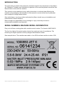
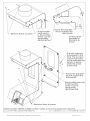
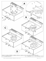
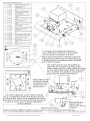
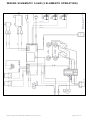
Jet 6 SERVICE MANUAL Marco Beverage Systems Ltd. 63d Heather Road, Sandyford Industrial Estate, Dublin 18, Republic of Ireland Service Manual 1000850# 1000851# 20-08-14.doc Ireland Tel: (01) 295 2674 Ireland Fax: (01) 295 3715 UK Tel: (0207) 274 4577 UK Fax: (0207) 978 8141 Page 1 of 15 CONTENTS PAGE INTRODUCTION 3 SERIAL NUMBER & MACHINE MODEL INFORMATION 3 GENERAL DESCRIPTION 4 ASSEMBLY & PARTS DRAWINGS FRONT PANEL REMOVAL TOP PANEL & BACK PANEL REMOVAL ELEMENT REMOVAL SPARE PARTS LOWER & DESCALING SPARE PARTS UPPER & DISPENSE VALVE REMOVAL 5 6 7 8 9 TROUBLESHOOTING –LCD DIAGNOSTIC GUIDE 10 TROUBLESHOOTING –GENERAL DIAGNOSTIC GUIDE 12 WIRING DRAWINGS WIRING SCHEMATIC 5.6kW (2 ELEMENTS OPERATING) WIRING SCHEMATIC 2.8kW (1 ELEMENT OPERATING) 13 14 GENERAL SPARE PARTS LIST 15 Service Manual 1000850# 1000851# 20-08-14.doc Page 2 of 15 INTRODUCTION The information provided in this manual is intended to assist in the maintenance of the Marco Jet 6 Brewers. For basic user information & operation of the machine please consult the User Manual which comes with the machine. This manual is not a substitute for any safety instructions or technical data affixed to the machine or its packaging. All information in this manual is current at the time of publication and is subject to change without notice. Only technicians or service providers authorised by Marco should carry out installation and maintenance of these machines. Marco accepts no responsibility for any damage or injury caused by incorrect or unreasonable installation and operation. SERIAL NUMBER & MACHINE MODEL INFORMATION Every unit will have a rating plate with a machine serial number. The format is MMYYXXXX The first four digits of the serial number denote the month and year of manufacture. The remaining four digits represent a factory assigned identification number. See example below. This machine was made in June 2014 and was machine number 1234. Service Manual 1000850# 1000851# 20-08-14.doc Page 3 of 15 GENERAL DESCRIPTION 1000850# Jet 6 5.6kW Electrical Connection Plumbing Fittings Pressure Dimensions Performance Height Width Depth (no plumbing or driptray) Depth (including plumbing fitting, no driptray) Depth (including plumbing fitting & including driptray) Tap Height to counter Tap Height to driptray Hot Water (if tap is installed): Immediate Draw Off Total Recovery rate at 5.6KW 1000851# Jet 6 2.8kW Electrical Connection Plumbing As above Dimensions Performance As above Hot Water: Immediate Draw Off Total Recovery rate at 2.8KW Service Manual 1000850# 1000851# 20-08-14.doc 5.6kW,230Vac c/w 1.5m flex 0.75” BSP Food grade inlet hose supplied 5-50 psi (35-345 kPa) Standard inlet hose protrudes out 47mm measured from the flat back panel. 840mm 310mm 410mm 445mm 490mm 162mm 132mm Approx. 5L + 0.9 litres/minute 0.9 litres/minute 2.8kW,230Vac c/w 1.5m flex & moulded plug Approx. 5L + 0.45 litres/minute 0.45 litres/minute Page 4 of 15 Service Manual 1000850# 1000851# 20-08-14.doc Page 5 of 15 Service Manual 1000850# 1000851# 20-08-14.doc Page 6 of 15 Service Manual 1000850# 1000851# 20-08-14.doc Page 7 of 15 RRANGEMENT Service Manual 1000850# 1000851# 20-08-14.doc Page 8 of 15 Service Manual 1000850# 1000851# 20-08-14.doc Page 9 of 15 TROUBLESHOOTING – LCD DIAGNOSTIC GUIDE: The Jet 6 uses an electronic diagnostic system to help determine faults. If an error is detected a message is displayed through the LCD screen. THERMISTOR ERROR Electronic check: This indicates that the thermistor is possibly measuring such a large resistance that it assumes the thermistor circuit is open. This indicates that the thermistor is possibly measuring zero resistance. It assumes the thermistor has failed sort circuit. The element and inlet valve are turned OFF when this error is detected This is a recoverable error. When the correct range of resistance is measured, normal operation resumes Probable causes: 1. The thermistor probe is unplugged from the 4way connector on the PCB or the thermistor has failed open circuit. 2. The thermistor has failed in a closed circuit manner. Action required: 1. Check that the thermistor is plugged in to the PCB correctly. If it is, replace the thermistor. OVERFILL ERROR Electronic check: This indicates that the overflow water level probe has been reached The element and inlet valve are turned OFF when this error is detected This is a recoverable error. When the water drops off the overflow water level probe, normal operation resumes. Probable causes: 1. The machine is wired incorrectly, e.g. the high level probe wire is connected to the overflow probe. 2. The tank has overfilled since the inlet solenoid has failed or is “weeping”. If the machine is turned off for a long time but still plumbed in this can cause it to fill. 3. The high level probe may have become coated in limescale and is allowing too much water in before it registers to stop. 4. If a brew is cancelled water circulating in the plumbing will return to the tank and possibly cause it to reach the low level probe (this is also more likely if the high level probe is scaled up) 5. Bubbles from the element can cause splashing inside the small tank which can trigger the overflow probe momentarily. Action required: 1. Dispense some water via the hot water outlet and see if the problem recurs. 2. Descale the tank paying special attention to the high level probe. 3. Check water pressure, if it is too low the solenoid may allow small amounts of water in. 4. Check the solenoid for debris which may cause it to jam partially open. Service Manual 1000850# 1000851# 20-08-14.doc Page 10 of 15 PROBES ERROR Electronic check: This indicates that the high level probe has been reached but the low level probe has not been detected. The element and inlet valve are turned OFF when this error is detected This is a recoverable error. If the low level probe is detected, normal operation resumes. Probable causes: 1. The low level probe is disconnected or has a faulty wiring connection. The probe will not function and so the machine will fill until the high level probe is reached. 2. The probes are connected incorrectly, so the water reaches the first/lowest probe but it is incorrectly wired as the high level probe. 3. The low level probe may have become coated in limescale and is not being detected so water continues to fill the machine until the high level probe is detected. Action required: 1. Re-wire the probes correctly. 2. Repair the faulty probe/connectors/wiring 3. Descale the low level probe. HEATER ERROR Electronic check: This indicates that the tank temperature has not risen in 20mins Probable causes: 1. The element is disconnected or has failed. Action required: 1. Replace the element. 2. Re-wire the elements correctly, 2.8kW machines should have the lower element connected. WAIT LOW PRESSURE Electronic check: This indicates that the tank temperature has not dropped in 6mins while the inlet solenoid is trying to allow in water. This is a recoverable error. When water is allowed in a temperature drop will occur and normal operation resumes Probable causes: 1. The water supply has been cut off or is lower than 2L/min. This could be a temporary event if some other appliances on the same water line is taking in a lot of water. 2. The inlet solenoid may have failed or is has a wiring error. Action required: 1. Replace the solenoid. 2. Check incoming the water supply. Service Manual 1000850# 1000851# 20-08-14.doc Page 11 of 15 TROUBLESHOOTING –GENERAL DIAGNOSTIC GUIDE: The Jet 6 may have problems which the electronics are unable to detect. LOW WATER OUTPUT The brew water should exit the sprayhead at approximately 2.1L/minute. During water calibration it should discharge 1000-1200g of hot water (960-1150ml). Probable causes: 1. The hose exiting the pump is kinked which restricts flow. 2. Other hoses exiting the upper circulation chamber are kinked which can effect flow. 3. The pump is faulty or is clogged/jammed. 4. Incorrectly calibrated. Action required: 1. Check for kinks in all hoses. 2. Check pump operation. Although the pump may function it may not be outputting an adequate supply. During calibration it should output 1000-1200g of water, or if dispensing using the hot water dispense outlet it should be approximately 2L per minute. The tube coming from the pump may be temporarily removed from the metal Y piece and fed directly into the basket, this can rule out any plumbing issues, a higher flow rate of 4-6L/min will be expected from the pump when operated in this way. 3. Recalibrate the water dispense. If a faulty scales is used the volume will be incorrect. HIGH WATER OUTPUT The brew water should exit the sprayhead at approximately 2.1L/minute. During most brew cycles the solenoid valve feeding the sprayhead should close at which time no water should exit the sprayhead after a draining time of approx. 10 seconds after the solenoid closes. Probable causes: 1. The valve feeding the sprayhead is faulty. The valve mounts onto a metal tube with some silicone tube. If too much tube is used it can rise up over the top of the metal mounting tube and cause the valve’s plunger to be forced into an open position. As both the valve and silicone tube are transparent it may be possible to see if the silicone tube is past the top of the metal tube. 2. Kinks in any tubes can cause flow problems in the machine which could cause unusually high flowrates. 3. Incorrectly calibrated. Action required: 1. Check the valve and remove and reseat it if necessary. 2. Check for kinks in all hoses. 3. Recalibrate the water dispense. If a dry basket is used during calibration then some water may be retained in the basket giving a lower estimate. If hot water is left to stand then some may evaporate giving a lower weight when weighed, so the machine will dispense too much as it thinks it has a lower flowrate than it actually has. GRINDER OUTPUT The grinder works on a timed basis, estimating how many grams are dispensed per second. During calibration if the grinder is empty and clean then grinds will cling to the grinder components and the 10 second calibration grind will dispense a lower weight than if the machine was in normal operation running for 10 seconds. So before calibrating a small amount of beans should be passed through the grinder. Adjusting bean type, roast, humidity, grinder settings etc. can also result in higher/lower weights than expected. Service Manual 1000850# 1000851# 20-08-14.doc Page 12 of 15 WIRING SCHEMATIC 5.6kW (2 ELEMENTS OPERATING) Service Manual 1000850# 1000851# 20-08-14.doc Page 13 of 15 WIRING SCHEMATIC 2.8kW (1 ELEMENT OPERATING) Service Manual 1000850# 1000851# 20-08-14.doc Page 14 of 15 GENERAL SPARE PARTS LIST (refer to earlier drawings for further parts listing) Part Number 1500985 1600691 1502260 1502158 1502151 1502171 1800301 1800690 1501559A 1600201 1600200C 1501182 1500840 1800770 2300024 2300277 1800402 2301338 1700169 8000151 8000240 Description ELEMENT 2.8kW 230V Thermistor Assembly Solenoid 24VDC Basket Lock Valve 12mm Bore 230V 30E Vent Vend VALVE DUMP 240Vac Valve Inlet 90 Deg 220V - 2L/min Gasket Sprayhead 186x146x6mm Water Inlet Hose WRC Pump Topsflo 24V DC P.C.B Jet Control P.C.B. Touchscreen 3.2inch Complete Cable Ribbon IDC 10way to 16Way 1m CONTACTOR B&J 240V AC O RING 4" RED SILICONE Basket Complete 233x136mm Driptray Complete JET Grommet Silicone 4mmID 7mmPanel dia Probe Triple 120mm/65mm/no tab Insulated Urn 6L Filter Paper Jet 380-152 (52gsm) Urn Cleanser (800g Tub) Service Manual 1000850# 1000851# 20-08-14.doc Page 15 of 15