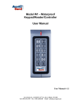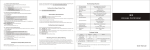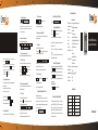
1
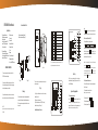
Technical Specification 3.1.1 To Add User card Press: 1 read card user ID number (000 to 999). # ( Press * if you want to save and exit) Reliable. Durable. Affordable Note: The user ID must be a unique 3 digit number. This is not the access password, it is just a ID number for the card, and the ID number must be different for each card. To add more than 1 card at a time: Enter the programming mode then press: 1 read card 1 user ID number read card 2 user ID number read card n user ID number(000 to 999) # 3.1.2 Use the card to release the door Simply swipe the card on the reader window, and the door will open. (Note: 1. All the steps below(from 3-7) are done in the Programming mode, that is * Master code # . 2. In each step when you finished the operation, if you want to save and exit from the programming mode, just press * ;; if you want to continue the programming, just go ahead to the next step directly until you finished, last press * to save and exit. ) finished, last press * to save and exit. ) 3. User Operation Mode for access There are 3 different options: Card only, card and password, Card or Password The optioned used is common to all users. (Note: you can only choose one of them) 3.1.3 To delete the card There are 3 options to delete the user, in engineering mode. a.) Press: 2 Read card # to delete individual user b.) Press: 2 user ID number # to delete individual user c.) Press: 2 0 0 0 0 # to delete all user (Note this is a dangerous option so please use with care) 3.1 Valid Card Mode (300 #) ( In this mode, the user can only open the door by the card) .6. 3.3 Valid card or password Mode (302 #) (In this mode, the user can only open the door by either the card or the password) 3.3.1 To Add User First add the card as for a card user in 3.1.1: Second, press * to exit from the programming mode, then alocate the card a Password as follows Press: * read card 1234 # Password # Re-enter Password # (Password is any four digits between 0000 - 9999 with the exception of 1234 which is reserved.) To add the multi users, please repeat the former step. 3.3.2 To release the door Read Card , the door will open. Password # , the door will open. 3.2 Valid card and password Mode (301#) (In this mode, the user can only open the door by the card and password together) 3.2.1 To Add User 1. Valid card only, Press: 3 0 0 # 2. Valid card and password, Press: 3 0 1 # 3. Valid card or password, Press: 3 0 2 # 3.2.2 To release the door Card + Password + # , and the door will open. 3.2.3 To delete a user Carry out the same procedure as 3.1.3 First add the card as for a card user in 3.1.1: Second, press * to exit from the programming mode, then alocate the card a Password as follows Press: * read card 1234 # Password # Re-enter Password # (Password is any four digits between 0000 - 9999 with the exception of 1234 which is reserved.) To add the multi users, please repeat the former step. .7. 3.3.3 To delete the user Carry out the same procedure as 3.1.3 Setting Alarm Signal Output Time Press: 5 new time from 00-99 minutes # Setting Door Open Detection Press: 6 0 0 # to disable this function (factory setting) Press: 6 0 1 # to enable this function. In order for this feature to work, door contacts must be connected. There are 2 programming functions that work together in this mode. a.)If door is not closed after opening, the keypad buzzer sounds. b.)If the door is forced open, keypad buzzer sounds and activates the alarm signal output. Specifications DC Supply Voltage: Low voltage input 12Vdc unregulated Current Consumption: 100mA @ quiescent maximum Door Relay: 3Amp 12Vdc Alarm output load: 150mA pull current Memory: Non volatile EPROM memory Codes: Keypad: 1 Master, 1000 cards and 1000 codes Card Types: EM or EM compatible Induction Distance: 3-7cm Wiring Connections: .8. Resetting To Factory Default Setting To reset the flash memory (see figure 3), turn off the power, press the RESET key(K2) on the PCB, hold it and re-power the device, keep holding it for around 5 seconds until hear beeps, means reset to factory default setting successfully. Note: Reset to factory default, the users information enrolled will lose, so use with care. .9. Remote Request to Exit Door open detection External A larm Tamper Protection: Negative loop, normally closed Keypad Housing: Metal Operating Temperature: -15 Nest Weight: Gross Weight: 500g 700g to 60 (5 oF to 140oF) Package Listing Setting Door Output Relay Strike Time (Default setting: 6 seconds) The door relay operating duration time can be set from 0 seconds to a maximum of 99 seconds. The factory default setting is 6 seconds and can be changed by programming the desired relay operation time. Press: 4 new time from 00-99 seconds # CFX-SKR -3500 Stand Alone Keypad & Proximity Reader Electric lock Setting Security A rrangement There are two levels of keypad security available for the SRK-3500. Press: 7 0 1 # to read 10 invalid cards or enter 4 wrong passwords in succession, the keypad is locked for 10 minutes. Press: 7 0 2 # to read 10 invalid cards or enter 4 wrong passwords in succession, the keypad activates buzzer and alarm signal output. To disable this feature: Press: 7 0 0 # factory default setting. 12 keys, 3 LED status indicators Reliable. Durable. Affordable Name Digital Keypad SKR-3500 Quantity User Manual 1 Screwdriver 1 Pastern Stopper Self Tapping Screws Remark 1 6*27mm, used for fixing 4 3.5*27mm, used for fixing 4 Please ensure that all the above contents are correct. If any are missing please notify the supplier. .10. User manual CFX-SRK-3500 Users Manual Internal Interface Circuit NOTE: please read these instructions carefully before attempting to install the SRK-3500 ALARM 12V GND D_IN OPEN NC +5V NC 20K NO ALARM 2K Tamper Switch 4.7R Alarm Switched negative when active 7 Yellow To Door EXIT Request Button Then Negative White 6 OPEN D_IN Brown To Door Contact Then To Negative 5 12V Red (+) 12Vdc Positive Regulated Power Input 4 GND Black (-) Negative Regulated Power Input 3 NO Blue Door Strike Relay N/O 2 COM Purple Door Strike Relay Com 1 NC Orange Door Strike Relay N/C Grey ALARM Yellow OPEN Brown D_IN R e d +12V Black GND Open door button Door Status Inspector +12V GND +V -V Blue NO Purple COM Orange NC Power on the locks keep opening +V -V Figure 4 COM Power Up In4148 The front cover can be permanently secured by using the short screw supplied GND Green Wiring 1.Attach the rear plate to a single or double gang electrical box or secure to the wall firmly with at least three flat head screws. 2.When wiring has been completed, attach the front cover to the rear plate. White Annunciator 1.Unplug the cable harness and connect the necessary cables, (See Figure 3). 2.Tape any wires that are unused. 3.Plug in the cable harness on the PCB , (See Figure 3) 4.attach the front cover(See Figure 4) Power on the locks keep opening +V + - Off p o wer th e locks k e ep o p ening + - OPEN Brown D_IN R e d +12V Black GND Engineer Programming Mode Blue NO 1. To enter programming mode Press: * 9999 # quickly and within 5 seconds, The red and green LED will flash rapidly then slowly. If no key is pressed in 30 seconds the unit will exit programming mode. Purple COM (Note: * button is the same as door bell Orange NC V+ V- .4. .3. ALARM Yellow Door Status Inspector Terminal Wire Connector 1 Function .2. Grey Open door button -V .1. 1.After all wiring is complete and the unit face plate is attached to the back plate, apply 12Vdc power to the unit. The red LED will be flashing. Special Power Supply PUSH Figure 2 +12V Figure 1 2. Master code: (Default code 9999) To change Master code: In programming mode Press: 0 new master code # re-enter new code # * Upon acceptance the red & green (yellow) LED lights and stops flashing. After pressing the * button the keypad will exit programming mode and the red LED will flash. Note: the master code must be 4-8 digit number. Off power the locks keep opening Figure 3 In4148 Grey Green Annunciator SW13 RELAY In4148 8 ALARM Note Press: * to save changes and exit from the engineer programming, when all programming has been completed, otherwise changes will not be saved. Do not plug the power supply or transformer into the mains until all wiring has been completed and the front cover secured. Mounting Every effort has been made to provide accurate information, however slight variations can occur. We also reserve the right K2 White GND If holes are to be drilled before mounting onto a wall, check for hidden cables and/or pipes before drilling. Use safety goggles when drilling or hammering in cable clips. RESET 9 NC There are no user serviceable parts contained with in the SRK-3500 access control keypad. NVM Reset Pin Green NO IMPORTANT INFORAMTION Wiring Cable Hamess 1.Alarm output interface (See Figure 1) 2.Electric lock interface (See Figure 2) NO 3:Wiring Connections Electric lock External bell External Push Switch Magnetic Contacts Alarm 2:Programmable Timers 4:Keypad Door relay time 00-99 seconds Door open detection 00-99 seconds 12 keys with backlight Alarm time 00-99 minutes 5:Programming memory: Non volatile EPROM memory COM 1:Programmable Functions Relay latching or momentary Relay strike time Change Codes 1 master, 1000 users & 1000 proximity cards Door open detection Common power s upply connection 10 Common(12V/3A) Specifications .5. (Note: 1. All the steps below(from 3-7) are done in the Programming mode, that is * Master code # . 2. In each step when you finished the operation, if you want to save and exit from the programming mode, just press * ;; if you want to continue the programming, just go ahead to the next step directly until you finished, last press * to save and exit. ) 3. User Operation Mode for access There are 3 different options: Card only, card and password, Card or Password The optioned used is common to all users. (Note: you can only choose one of them) 1. Valid card only, Press: 3 0 0 # 2. Valid card and password, Press: 3 0 1 # 3. Valid card or password, Press: 3 0 2 # symbol button) .6.