1
ER2-I&S-04
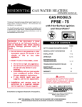
INSTALLATION AND SERVICE MANUAL
Swimming Pool Heaters
150,000 - 399,999 Btu/hr Models
equipment and is not covered under the manufacturer's
warranty (See Facts About Water Chemistry).
IMPORTANT:
This is a gas appliance and should be installed by a
licensed electrician and/or certified gas supplier. Service
must be performed by a qualified service installer, service
agency or the gas supplier.
2. Excessive pitting and erosion on the inside of the copper tube
may be caused by too much water velocity through the tubes
and is not covered by the manufacturer's warranty (See Water
Connections, Maximum Flow Rates for flow requirements).
WARNING
SPECIAL INSTRUCTIONS TO OWNER
If the information in these instructions is not
followed exactly, a fire or explosion may result
causing property damage, personal injury or death.
NOTE:
Retain this manual for future reference.
This pool heater MUST NOT be installed in any
location where gasoline or flammable vapors are
likely to be present, unless the installation is such to
eliminate the probable ignition of gasoline or
flammable vapors.
This manual supplies information for the installation, operation
and servicing of the appliance. It is strongly recommended that
this manual be reviewed completely before proceeding with an
installation.
WARNING
WHAT TO DO IF YOU SMELL GAS
Improper installation, adjustment, alteration,
service or maintenance can cause injury or property
damage. Refer to this manual for assistance or
additional information, consult a qualified installer,
service agency or the gas supplier.
• Do not try to light any appliance.
• Do not touch any electric switch; do not use any phone in your
building.
• Immediately call your gas supplier from a neighbors phone.
Follow the gas supplier's instructions.
CHECKING EQUIPMENT
Upon receiving equipment, check for signs of shipping damage.
Pay particular attention to parts accompanying the pool heater
which may show signs of being hit or otherwise being
mishandled. Verify total number of pieces shown on packing
slip with those actually received. In case there is damage or a
shortage, immediately notify the carrier.
• If you cannot reach your gas supplier, call the fire department.
Installation and service must be performed by a qualified
installer, service agency or the gas supplier.
WARRANTY
Do not use this pool heater if any part has been under water.
The possible damage to a flooded pool heater can be
extensive and present numerous safety hazards. Any pool
heater that has been under water must be replaced.
Factory warranty (shipped with unit) does not apply to units
improperly installed or improperly operated.
Experience has shown that improper installation or system
design, rather than faulty equipment, is the cause of most
operating problems.
OWNER WARNING
The information contained in this manual is intended for use by
qualified professional installers, service technicians or gas
suppliers. Consult your local expert for proper installation
or service procedures.
1. Improper maintenance of pool water chemistry resulting
high water hardness and high alkalinity that results in a lime
scale build up in the copper tube is not the fault of the
1
MNL 7012
CONTENTS
Warranty . . . . . . . . . . . . . . . . . . . . . . . . . . . . . . . . . . .1
Safety Warnings . . . . . . . . . . . . . . . . . . . . . . . . . . . . .1
Spa and Hot Tub Safety . . . . . . . . . . . . . . . . . . . . . . .2
Codes . . . . . . . . . . . . . . . . . . . . . . . . . . . . . . . . . . . . .3
Location . . . . . . . . . . . . . . . . . . . . . . . . . . . . . . . . . . .3
Combustible Floor Kits . . . . . . . . . . . . . . . . . . .4
Clearances . . . . . . . . . . . . . . . . . . . . . . . . . . . . . . . . . .5
Combustion/Ventilation Air . . . . . . . . . . . . . . . . . . . .5
Vent System Options . . . . . . . . . . . . . . . . . . . . . . . . .8
Outdoor Installation . . . . . . . . . . . . . . . . . . . . .8
Installation of Vent Kits . . . . . . . . . . . . . . . . .10
Conventional Venting . . . . . . . . . . . . . . . . . . .11
Vent Terminations . . . . . . . . . . . . . . . . .12
Vent Clearances . . . . . . . . . . . . . . . . . . .13
Vertical DirectAire . . . . . . . . . . . . . . . . . . . . .14
Powered Sidewall Venting . . . . . . . . . . . . . . .17
Horizontal DirectAire . . . . . . . . . . . . . . . . . . .19
E-Rite Sidewall Venting . . . . . . . . . . . . . . . . .21
Gas Supply . . . . . . . . . . . . . . . . . . . . . . . . . . . . . . . .25
Gas Supply Pressures . . . . . . . . . . . . . . . . . . . . . . . .25
Net Manifold Pressure . . . . . . . . . . . . . . . . . .25
Gas Pipe Sizing . . . . . . . . . . . . . . . . . . . . . . . .26
LP Gas Installations . . . . . . . . . . . . . . . . . . . .26
Gas Line Connection . . . . . . . . . . . . . . . . . . . .27
Manifold Pressure Adjustment . . . . . . . . . . . .28
Supply Pressure Measurement . . . . . . . . . . . .30
Water Connections . . . . . . . . . . . . . . . . . . . . . . . . . .30
Minimum Flows . . . . . . . . . . . . . . . . . . . . . . . . . . . .31
Auxiliary Bypass . . . . . . . . . . . . . . . . . . . . . . . . . . .31
Automatic Chlorinators/Chemical Feeders . . . . . . .32
Relief Valve . . . . . . . . . . . . . . . . . . . . . . . . . . . . . . .32
Gas Valve . . . . . . . . . . . . . . . . . . . . . . . . . . . . . . . . .32
Electrical Requirements . . . . . . . . . . . . . . . . . . . . . .33
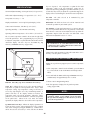
Digital Temperature Control . . . . . . . . . . . . . . . . . . .33
Adjusting Setpoints . . . . . . . . . . . . . . . . . . . . .34
Temperature Adjustment Procedure . . . . . . . .34
Error Messages . . . . . . . . . . . . . . . . . . . . . . . .35
Temperature Limit Control . . . . . . . . . . . . . . . . . . . .36
Water Pressure Switch . . . . . . . . . . . . . . . . . . . . . . .36
Lighting Instructions . . . . . . . . . . . . . . . . . . . . . . . . .36
Ignition System . . . . . . . . . . . . . . . . . . . . . . . . . . . . .37
Operation & Diagnostic Lights . . . . . . . . . . . . . . . .38
Ignition & Control Timings . . . . . . . . . . . . . . . . . . .39
Energy Saving Recommendations . . . . . . . . . . . . . .39
Maintenance . . . . . . . . . . . . . . . . . . . . . . . . . . . . . . .39
Flame Patterns . . . . . . . . . . . . . . . . . . . . . . . . .39
Burner Cleaning . . . . . . . . . . . . . . . . . . . . . . .40
Heat Exchanger Removal and Cleaning . . . . .41
HSI Replacement . . . . . . . . . . . . . . . . . . . . . .42
Combustion Air Adjustment . . . . . . . . . . . . . .43
Gas Train . . . . . . . . . . . . . . . . . . . . . . . . . . . . .44
Terminal Strip / Remote Controls . . . . . . . . . .44
Water Chemistry . . . . . . . . . . . . . . . . . . . . . . . . . . . .45
Heat Exchanger Inspection . . . . . . . . . . . . . . . . . . . .46
Freeze Protection . . . . . . . . . . . . . . . . . . . . . . . . . . .46
Draining the Heat Exchanger . . . . . . . . . . . . .46
IMPORTANT:
Consult and follow all local Building and Fire
Regulations and other Safety Codes that apply to this
installation. Consult local gas utility company to
authorize and inspect all gas and flue connections.
Your conventionally vented gas unit must have a supply of fresh
air circulating around it during burner operation for proper gas
combustion and proper venting.
WARNING
Should overheating occur or the gas supply fail to
shut off, do not turn off or disconnect the electrical
supply to the pump. Instead, turn off the manual
gas control valve to the appliance at a location
external to the appliance.
PREVENTION OF FREEZING
Heat exchangers and headers damaged by freezing are not
covered by warranty.
Refer to the WINTERIZING section.
SPA AND HOT TUB SAFETY
The following safety rules must be observed while operating a
spa or hot tub.
1. Spa or hot tub water temperatures should never exceed 104ºF
(40ºC). A temperature of 100ºF (38ºC) is considered safe for
a healthy adult. Special caution is suggested for young
children.
2. Drinking of alcoholic beverages before or during spa or hot
tub use can cause drowsiness which could lead to
unconsciousness and subsequently result in drowning.
3. Pregnant women beware! Soaking in water above 102ºF
(39ºC) can cause fetal damage during the first three months
of pregnancy (resulting in birth of brain-damaged or a
deformed child). Pregnant women should observe the 100ºF
(38ºC) maximum rule.
4. Before entering the spa or hot tub, users should check the
water temperature with an accurate thermometer; spa or hot
tub thermostats may err in regulating water temperatures by
as much as 4º Fahrenheit (2ºC).
5. Persons with a medical history of heart disease, circulatory
problems, diabetes or blood pressure problems should obtain
their physician's advice before using spas or hot tubs.
2
6. Persons taking medications which induce drowsiness, such as
tranquilizers, antihistamines or anticoagulants, should not
use spas or hot tubs.
INSTALLATION PROCEDURE
WARNING
To minimize the possibility of serious personal
injury, fire, or damage to your pool heater, never
violate the following safety rules.
1.
Pool heaters are heat producing appliances. To
avoid damage or injury, do not store materials
against the pool heater or the vent-air intake
system. Use proper care to avoid unnecessary
contact (especially children) with the pool
heater and vent-air intake components.
2.
Never cover your pool heater, lean anything
against it, store trash or debris near it, stand on
it or in any way block the flow of fresh air to
your pool heater.
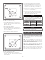
3.
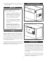
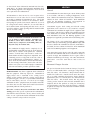
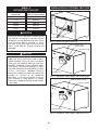
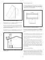
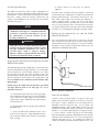
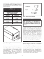
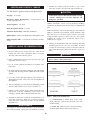
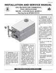
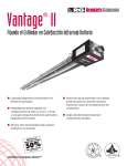
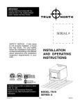
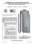
FIG. 1 Front View 150,000 - 399,999 Btu/hr Models
UNDER NO CIRCUMSTANCES must
flammable materials such as gasoline or paint
thinner be used or stored in the vicinity of this
pool heater, vent-air intake system or any
location from which fumes could reach the pool
heater or vent-air intake system.
CODES
The pool heater shall be installed in accordance with those
installation regulations in force in the local area where the
installation is to be made. These shall be carefully followed in
all cases. Authorities having jurisdiction shall be consulted
before installations are made. In the absence of such
requirements, the installation shall conform to the latest edition
of the National Fuel Gas Code, ANSI Z223.1 and/or
CAN/CGA-B149 Installation Code.
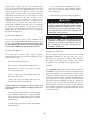
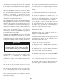
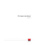
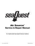
FIG. 2 Rear View 150,000 - 399,999 Btu/hr Models
As an option, all pool heaters may be ordered with heat
exchanger construction that conforms to the latest edition of the
ASME Boiler and Pressure Vessel Code, Section IV, Part HLW.
See Note on page 31 for additional information.
LOCATION OF UNIT
1. Locate the pool heater so that if water connections should
leak, water damage will not result in damage to the area
adjacent to the pool heater or to the structure. When such
locations cannot be avoided, it is recommended that a suitable
drain pan, adequately drained, be installed under the pool
heater. The pan must not restrict combustion air flow. Under
no circumstances is the manufacturer to be held responsible
for water damage in connection with this pool heater, or any
of its components.
2. The indoor pool heaters must be installed so that the ignition
system components are protected from water (dripping,
spraying, rain, etc.) during appliance operation and service
(fan adjustment, control replacement, etc.).
3
3. Pool heaters located in a residential garage and in adjacent
spaces that open to the garage and are not part of the living
space of a dwelling unit must be installed so that all burners
and burner ignition devices have a minimum clearance of not
less than 18” (46cm) above the floor. The pool heater must
be located or protected so that it is not subject to physical
damage by a moving vehicle.
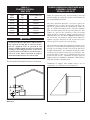
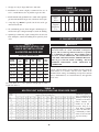
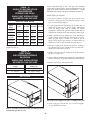
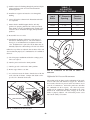
TABLE - A
COMBUSTIBLE FLOOR KITS
Input Btu/hr
Kit Number
150,000
CFK3300
199,999
CFK3300
4. DO NOT install this pool heater in any location where
gasoline or flammable vapors are likely to be present.
250,000
CFK3301
300,000
CFK3301
5. The pool heater must be installed on a level, non-combustible
floor. Concrete over wood is not considered a non-combustible
floor. Maintain required clearances from combustible surfaces.
399,999
CFK3302
8.Outdoor models require the use of the factory supplied
outdoor vent cap assembly. The outdoor vent cap is mounted
on the flue outlet of the pool heater as shipped. Outdoor
models must not be installed directly on the ground. The
outdoor unit must be installed on a concrete, brick, block or
other non-combustible pad. Outdoor models have additional
special location and clearance requirements. These are
specifically addressed in the Venting Section under Outdoor
Installation. Do not install in locations where rain from
building runoff drains or sprinkler systems will spill onto the
pool heater. A windproof cabinet protects the unit from weather.
6. The pool heater must not be installed on carpet or other
combustible material.
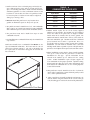
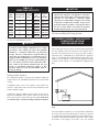
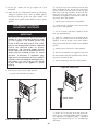
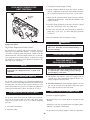
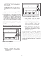
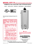
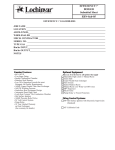
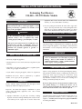
7. For installation on a combustible floor only when installed on
a special base:
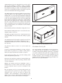
Pool heaters installed over a combustible floor MUST use the
Special Combustible Floor Base. The heater must be centered
on the base as shown in Figure 3. The correct part number for
the required base is noted on the rating plate of each unit and
listed in Table A.
9.Indoor installations require that the factory installed outdoor
vent cap be removed from the pool heater to allow the
installation of a flue pipe. Specific instructions for the
removal of the outdoor cap are addressed in the venting
section. Indoor installations require adequate supplies of
clean combustion air for proper operation. Optional venting
arrangements may allow direct pipe connection from the unit
to the outside for combustion air. See the "Venting Options"
section of this manual.
10.This pool heater must be installed at least five feet from the
inside wall of a pool unless separated from the pool by a solid
fence, wall or permanent barrier.
11. When a pool heater is installed within the pool structure, the
structure shall be designed such that in the event of a fuel gas
leak, the leaking gas is vented to the exterior of the pool structure.
Combustible Floor Base
FIG. 3 Special Combustible Floor Base
4
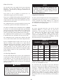
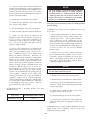
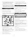
CLEARANCES FROM
COMBUSTIBLE CONSTRUCTION
COMBUSTION AND VENTILATION
AIR REQUIREMENTS FOR
CONVENTIONALLY VENTED APPLIANCES
AND SIDEWALL VENTED APPLIANCES
24" Service Clearance
Provisions for combustion and ventilation air must be in
accordance with Section 5.3, Air for Combustion and
Ventilation, of the latest edition of the National Fuel Gas Code,
ANSI Z223.1, in Canada CAN/CGA-B149 Installation Code
for Gas Burning Appliances and Equipment, or applicable
provisions of the local building codes.
The equipment room MUST be provided with properly sized
openings to assure adequate combustion air and proper
ventilation when the unit is installed with conventional venting
or sidewall venting and drawing combustion air from the room.
3" Combustible Clearance
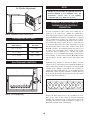
FIG. 4 Clearances from Combustible Construction (Front)
6"
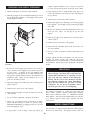
Indoor
models
FIG. 4a Clearances from Combustible Construction (Back)
Clearances from Combustible Construction:
Right Side - 3" (7.6 cm)(24" (0.61m) suggested for service)
Rear (Outdoor) - 3" (7.6 cm) (3" minimum from any surface)
Rear (Indoor) - 6" (15.2 cm) (6" minimum from any surface)
Left Side - 3" (7.6 cm)
Front - ALCOVE* (24" (0.61m) suggested for service)
Top - 3" (7.6 cm) (24" (0.61m) suggested for service)
Flue - 6" (15.2 cm)
Hot Water Pipes - 1" (25.4mm)
*An ALCOVE is a closet without a door.
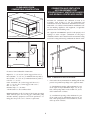
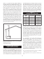
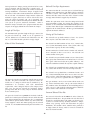
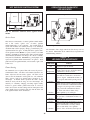
FIG. 5 Combustion Air Direct from Outside
1. If air is taken directly from outside the building with no duct,
provide two permanent openings to the equipment room:
(a) Combustion air opening, with a minimum free area
of one square inch per 4000 Btu/hr input (5.5 cm2 per
kW). This opening must be located within 12" (30 cm)
of the bottom of the enclosure.
Maintain minimum specified clearances for adequate operation.
Allow sufficient space for servicing pipe connections, pump
and other auxiliary equipment, as well as the pool heater. See
rating plate for specific service clearance requirements.
(b) Ventilation air opening, with a minimum free area
of one square inch per 4000 Btu/hr input (5.5cm2 per
kW). This opening must be located within 12" (30cm)
of the top of the enclosure.
5
FIG. 8 Combustion Air from Outside - Single Opening
FIG. 6 Combustion Air Through Ducts
2. If combustion and ventilation air is taken from the outdoors
using a duct to deliver the air to the equipment room, each of
the two openings should be sized based on a minimum free
area of one square inch per 2000 Btu/hr (11cm2 per kW).
4. If a single combustion air opening is provided to bring
combustion air in directly from the outdoors, the opening
must be sized based on a minimum free area of one square
inch per 3000 Btu/hr (7cm2 per kW). This opening must be
located within 12" (30cm) of the top of the enclosure.
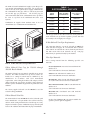
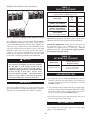
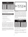
TABLE - B
MINIMUM RECOMMENDED COMBUSTION
AIR SUPPLY TO EQUIPMENT ROOM
Combustion Air Source
FIG. 7 Combustion Air from Interior Space
3. If air is taken from another interior space, each of the two
openings specified above should have a net free area of one
square inch for each 1000 Btu/hr (22cm2 per kW) of input,
but not less than 100 square inches (645cm2).
Boiler
Input
Outside Air*
2 Openings
Outside Air*
1 Opening
Inside Air
2 Openings
150,000
37.5 in2
(242 cm2)
50.0 in2
(323 cm2)
150 in2
(968 cm2)
199,999
50.0 in2
(323 cm2)
66.7 in2
(430 cm2)
200 in2
(1290 cm2)
250,000
62.5 in2
(403 cm2)
83.3 in2
(537 cm2)
250 in2
(1613 cm2)
300,000
75.0 in2
(484 cm2)
100 in2
(645 cm2)
300 in2
(1935 cm2)
399,999
100 in2
(645 cm2)
133 in2
(858 cm2)
400 in2
(2581 cm2)
*Outside air openings shall directly communicate with the
outdoors. When combustion air is drawn from the outside
through a duct, the net free area of each of the two openings
must have twice (2 times) the free area required for Outside
Air/2 Openings. The above requirements are for the pool heater
only, additional gas fired appliances in the equipment room will
require an increase in the net free area to supply adequate
combustion air for all appliances. Combustion air requirements
6
are based on the latest edition of the National Fuel Gas Code,
ANSI Z223.1, in Canada CAN/CGA-B149 Installation Code
for Gas Burning Appliances and Equipment. Check all local
code requirements for combustion air.
VENTING
General
Vent installations for connection to gas vents or chimneys must
be in accordance with Part 7, "Venting of Equipment," of the
latest edition of the National Fuel Gas Code, ANSI Z223.1, in
Canada, the latest edition of CAN/CGA - B149 Installation
Codes for Gas Burning Appliances and Equipment or
applicable provisions of the local building codes.
All dimensions are based on net free area in square inches.
Metal louvers or screens reduce the free area of a combustion
air opening a minimum of approximately 25%. Check with
louver manufacturers for exact net free area of louvers. Where
two openings are provided, one must be within 12" (30 cm) of
the ceiling and one must be within 12" (30 cm) of the floor of
the mechanical room. Each opening must have net free area as
specified in Table B. Single openings shall be installed within
12" (30 cm) of the ceiling.
Conventional negative draft venting and sidewall venting
applications, where outside air is used, must have adequate
combustion and ventilation air supplied to the equipment room
in accordance with the latest edition of the National Fuel Gas
Code, ANSI Z223.1, in Canada, the latest edition of CAN/CGA B149 Installation Codes for Gas Burning Appliances and
Equipment, or applicable provisions of the local building codes.
CAUTION
Under no circumstances should the mechanical room
ever be under a negative pressure. Particular care
should be taken where exhaust fans, attic fans,
clothes dryers, compressors, air handling units, etc.,
may take away air from the unit.
The distance of the vent terminal from adjacent buildings,
windows that open and building openings MUST comply with
the latest edition of the National Fuel Gas Code, ANSI Z223.1,
in Canada, the latest edition of CAN/CGA - B149 Installation
Codes for Gas Burning Appliances and Equipment.
The combustion air supply must be completely free of
any flammable vapors that may ignite or chemical fumes
which may be corrosive to the pool heater. Common
corrosive chemcial fumes which must be avoided are
fluorocarbons and other halogenated compounds, most
commonly present as refrigerants or solvents, such as
Freon, trichlorethylene, perchlorethylene, chlorine, etc.
These chemicals, when burned, form acids which attack
the heat exchanger finned tubes, headers, flue collectors,
and the vent system. The result is improper combustion
and a non-warrantable, premature pool heater failure.
Vent connection is made directly to the flue outlet connection
on the unit. No additional draft diverter or barometric damper is
required on single unit installations when a negative draft is
maintained within the specified range. The connection from the
pool heater's vent to the stack must be made as direct as
possible.
Barometric Damper Location
The preferred location for the barometric damper (if required)
is in a tee or collar installed in the vertical pipe, rising from the
unit’s flue outlet. The barometric damper MUST NOT be
installed in a bull head tee installed on the unit’s flue outlet.
The tee or collar containing the barometric damper should be
approximately three feet vertically above the connection to the
unit’s flue outlet. This location ensures that any positive
velocity pressure from the unit’s internal combustion fan is
dissipated and the flue products are rising due to buoyancy
generated from the temperature of the flue products. Adjust the
weights on the damper to ensure that draft is maintained within
the specified range.
EXHAUST FANS: Any fan or equipment which exhausts air
from the equipment room may deplete the combustion air
supply and/or cause a downdraft in the venting system.
Spillage of flue products from the venting system into an
occupied living space can cause a very hazardous condition that
must be immediately corrected. If a fan is used to supply
combustion air to the equipment room, the installer must make
sure that it does not cause drafts which could lead to nuisance
operational problems with the pool heater.
DirectAire Vertical, DirectAire Horizontal and E-Rite
Venting systems have specific requirements for combustion air
ducts from the outside which are directly connected to the pool
heater. See the requirements for this combustion air duct in the
venting section for each specialized vent system.
7
IMPORTANT:
OUTDOOR INSTALLATION
Examine the venting system at least once a year.
Check all joints and vent pipe connections for
tightness. Also check for corrosion or deterioration.
Immediately correct any problems observed in the
venting system.
Units are self venting and can be used outdoors when installed
with the factory supplied Outdoor Vent Cap. The outdoor vent
cap is mounted directly to the rear of the pool heater as shipped
from the manufacturer and covers the flue outlet and
combustion air inlet openings on the jacket. No additional vent
piping is required.
VENT SYSTEM OPTIONS
WARNING
This pool heater has six venting options. They are: (1)
Conventional Negative Draft Venting with vertical rooftop
flue termination and combustion air supplied from the
equipment room, (2) Vertical DirectAire Venting with a
vertical conventional vent for flue products and a combustion
air pipe from either the sidewall or roof top, (3) Powered
Sidewall Venting to exhaust flue products out a sidewall with
a powered vent assembly and combustion air supplied from the
equipment room (4) Horizontal DirectAire Venting with a
powered vent assembly to exhaust the flue products out a
sidewall and a combustion air pipe from the sidewall, (5) ERite Sidewall Venting which uses the internal combustion air
fan to exhaust the flue products out a sidewall vent termination
with a limited vent length. Combustion air for an E-Rite
Sidewall vent must be supplied with a combustion air pipe from
the sidewall, (6) Outdoor Venting using the factory supplied
air inlet/vent cap installed on the unit. All pool heaters are
shipped from the factory equipped for Outdoor Installation. All
other optional vent systems require the removal of the outdoor
vent cap and installation of specific vent kits and venting
materials. The following is a detailed explanation of the
installation requirements for each venting system, components
used and part numbers of vent kits for each model.
The flue products discharged from the flue outlet on
the outdoor vent cap may be very hot. Avoid
touching or other direct contact with the flue gases
or the vent cap assembly. These components are
HOT and direct contact can result in burns.
WARNING
Outdoor models MUST be installed outdoors and
MUST use the outdoor vent cap assembly supplied
by the manufacturer. Personal injury or product
damage may result if any other cap is used or if an
outdoor model is used indoors. All covers, doors and
jacket panels must be properly installed to insure
proper operation and prevent a hazardous
condition.
CAUTION
Pool heaters which are shut down or will not operate
may experience freezing due to convective air flow in
the outdoor vent cap installed on the unit. If
operated in cold climates, continuous pump
operation is recommended to help prevent freezing
of pool water in an outdoor installation. Proper
freeze protection must be provided. A pool heater
that is not in use in the winter season must be
properly drained and winterized. See Freeze
Protection.
The Outdoor Vent System
Combustion air supply must be free of contaminants (See
Combustion and Ventilation Air). To prevent recirculation of
the flue products into the combustion air inlet, follow all
instructions in this section.
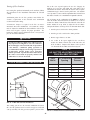
Outdoor Vent/Air Inlet Location
The venting areas must never be obstructed. Keep area clean and
free of combustible and flammable materials. Maintain a minimum
clearance of 3" (76 mm) to combustible surfaces and a minimum
of 3" (76 mm) clearance to the air inlet. To avoid a blocked air inlet
or blocked flue condition, keep the outdoor cap air inlet, flue outlet
and drain slot clear of, leaves, debris, snow, ice, etc.
FIG. 9 Outdoor Installation Illustration
8
A unit should not be located so that high winds can deflect off of
adjacent walls, buildings or shrubbery causing recirculation.
Recirculation of flue products may cause operational problems,
bad combustion or damage to controls. The unit should be located
at least 3 feet (0.19m) from any wall or vertical surface to prevent
adverse wind conditions from affecting performance.
The outdoor pool heater must not be installed in an area that is
enclosed by walls or a fence that will block free wind movements
around the unit. Free movement of wind around the outdoor unit
is required to carry away the flue products and provide combustion
air. The flue outlet/combustion air inlet cap of an outdoor pool
heater must not be installed closer than 10 feet (3.05m) from an
inside corner of an L-shaped structure. Walls or enclosed fencing
may cause eddy currents which can re-circulate the flue products
into the combustion air inlet. Recirculation of flue products may
cause operational problems, bad combustion or non-warrantable
damage to controls.
FIG. 10 Outdoor Vent Cap (Outside View)
Do not install the pool heater with outdoor venting under a deck.
Do not install an outdoor pool heater in a well, stairwell, alcove,
courtyard or other recessed area.
The outdoor cap must be located 4 feet (1.22m) below and 4 feet
(1.22m) horizontally from any window, door, walkway or gravity
air intake.
The combustion air inlet of the outdoor cap must be located at least
one foot (0.30m) above grade and above normal snow levels.
The pool heater must be at least 10 feet (3.05m) away from any
forced air inlet.
FIG. 11 Outdoor Vent Cap Installed on Unit
The pool heater must be at least 3 feet (0.91m) outside any
overhang.
The Outdoor Vent Cap Kit
The required outdoor cap part numbers are listed by unit size.
The venting kit must be furnished by the manufacturer in
accordance with CSA International requirements. An outdoor
vent cap kit is mounted on the pool heater as shipped from the
factory. The kit includes the flue outlet/combustion air inlet
assembly and gasket. Since the outdoor vent cap assembly is
supplied with each pool heater, the following part numbers are
provided for service part information.
Clearances around outdoor installations can change with time.
Do not allow the growth of trees, shrubs or other plants to
obstruct the proper operation of the outdoor vent system.
Do not install in locations where rain from building runoff
drains will spill onto the pool heater.
Do not locate the pool heater so that water from sprinklers may
spray directly on the unit. Water may damage controls or other
electrical components.
Multiple unit outdoor pool heater installations require a
minimum of 4 feet (1.22 m) clearance between the vent cap and
air inlet of adjacent heater to prevent recirculation of flue
products.
Flue gas condensate can freeze on exterior walls or on the vent
cap of a pool heater operated in the winter months. Frozen
condensate on the vent cap can result in a blocked flue
condition. Some discoloration to exterior building or unit
surfaces can be expected. Adjacent brick or masonry surfaces
should be protected with a rust resistant sheet metal plate.
9
TABLE - C
OUTDOOR VENT CAP KITS
Input Btu/hr
Outdoor Cap Kit Number
150,000
ODK3040
199,999
ODK3040
250,000
ODK3041
300,000
ODK3042
399,999
ODK3042
INSTALLATION OF OPTIONAL VENT KITS
CAUTION
Pool heaters which are shut down or will not operate
may experience freezing due to convective air flow
through the vent cap installed on the unit. Proper
freeze protection must be provided, see Freeze
Protection. A pool heater that is not in use in the
winter season must be properly drained and
winterized.
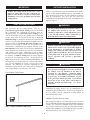
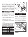
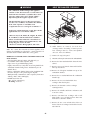
REMOVE MOUNTING SCREWS
FIG. 12 Removal of Outdoor Vent Cap
GREY SPONGE GASKET
ROUND GASKET
INLET AIR COLLAR
CAUTION
An Outdoor Installation, DirectAire Vent or an
E-Rite Vent into dead air spaces such as alleys,
atriums and inside corners can cause recirculation
of flue gases. Recirculation of flue gases will cause
incomplete combustion, sooting, premature failure
of the jacket, vent and heat exchanger as well as
icing of the combustion air intake during operation
in severe cold weather. Minimum clearances
between the combustion air intake and exhaust vent
terminal are specified in the installation
instructions. To prevent recirculation of the flue
gases, maintain as much distance as possible
between the combustion air intake and the exhaust
vent terminal.
FLUE ADAPTER
FIG. 13 Installation of Flue Adapter and Air Inlet Collar
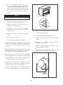
GREY SPONGE GASKET
INLET AIR COVER
FLUE ADAPTER
FIG. 14 Installation of Flue Adapter and Inlet Air Cover
10
No additional draft diverter or barometric damper is required on
single unit installations with a dedicated stack and a negative
draft within the specified range of a negative 0.02 to 0.08
inches water. If the draft in a dedicated stack for a single unit
installation exceeds the maximum specified draft, a barometric
damper must be installed to control draft. Multiple unit
installations with combined venting or common venting of this
pool heater with other Category I negative draft appliances
requires that each pool heater must have a barometric damper
installed to regulate draft within the proper range.
Whenever a vent option other than outdoor installation is
desired, the outdoor vent cap assembly MUST be removed and
an optional vent kit must be installed on the pool heater. The
vent kit allows connection of the flue and/or a combustion air
pipe. The vent kit includes the flue adapter and an air inlet collar
to allow connection of an air inlet pipe or an air inlet cover
when combustion air is drawn from the equipment room.
Remove the screws surrounding the outdoor vent cap and the
two screws in the divider between the flue outlet and air inlet
chambers on the vent cap. Use the screws removed from the
outdoor vent cap to secure the components in the vent kit.
Mount the flue adapter on the back of the pool heater over the
flue outlet. Mount the air inlet collar or air inlet cover over the
combustion air inlet opening on the rear of the jacket. Seal the
flue adapter and air inlet collar with the gaskets provided in the
kit. The flue adapter transitions the rectangular flue outlet to a
round flue pipe connection and turns the flue outlet vertical for
ease of installation. Vent pipe connection is made directly to the
outlet of the flue adapter. The air inlet collar allows connection
of a round pipe to the pool heater to supply combustion air. The
inlet air cover provides a grill to limit the entrance of foreign
matter into the pool heater’s air inlet.
TABLE - D
CONVENTIONAL VENT DATA
Input
Btu/hr
Conventional
Vent Flue Size
Conventional
Vent Kit Number
150,000
5"
CVK3000
199,999
5"
CVK3000
250,000
5"
CVK3000
300,000
5"
CVK3001
399,000
6"
CVK3002
The negative draft in a conventional vent installation must be
within the range of a negative 0.02 to 0.08 inches water to
insure proper operation. All draft readings are made while unit
is in stable operation (approximately 2 to 5 minutes).
Remember that the draft in a conventional negative draft vent
may vary seasonally. A pool heater with a high draft when
operating in the winter months may have a much lower draft in
the summer. Initial set-up of a vent system with a draft of not
more than a negative 0.05 inches water will generally insure
that increased draft in the winter months will not exceed the
specified maximum. Maximum draft can not exceed a negative
0.08 inches of water.
On a conventionally vented, negative draft pool heater, the
connection from the vent to the stack or vent termination
outside the building MUST be made with listed Type "B"
double wall (or equivalent) vent connectors and must be direct
as possible with no reduction in diameter. Use the National
Fuel Gas Code venting tables for double wall vent to properly
size all vent connectors and stacks. The Type "B" vent and
accessories, such as firestop spacers, thimbles, caps, etc.,
MUST be installed in accordance with the manufacturers
instructions. The vent connector and firestop must provide
correct spacing to combustible surfaces and seal to the vent
connector on the upper and lower sides of each floor or ceiling
through which the vent connector passes.
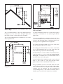
FIG. 15 Conventional Negative Draft Vertical Venting with
Combustion Air Louvers
Conventional Venting
A CONVENTIONAL NEGATIVE
DRAFT VENTING SYSTEM
The outdoor vent cap assembly MUST be removed before any
connection to a conventional negative draft vent system can be
made. A conventional vent adapter kit MUST be installed on
the pool heater's flue outlet. The conventional vent kit includes
the flue adapter and an air inlet cover. Mount the air inlet cover
over the combustion air inlet opening on the rear of the jacket.
Any vent materials specified must be listed by a nationally
recognized test agency for use as vent material.
Locate the pool heater as close as practicable to chimney or gas
vent.
11
Avoid long horizontal runs of the vent pipe, 90° elbows,
reductions and restrictions. Horizontal portions of the venting
system shall be supported to prevent sagging. Horizontal runs
must slope upwards not less than 1/4 inch per foot (21 mm/m)
from the appliance to the vent terminal. Follow manufacturers
instructions.
properly vents when tested as above, return doors,
windows, exhaust fans, fireplace dampers and other
gas burning appliances to their previous conditions of
use.
(g) Any improper operation of the common venting
system should be corrected so that the
installation conforms to the latest edition of the
National Fuel Gas Code, ANSI Z223.1, in Canada, the
latest edition of CAN/CGA - B149 Installation Codes
for Gas Burning Appliances and Equipment. When
resizing any portion of the common venting system,
the common venting system should be resized to
approach the minimum size as determined using
the appropriate tables in the latest edition of the
National Fuel Gas Code, ANSI Z223.1, in Canada, the
latest edition of CAN/CGA - B149 Installation Codes
for Gas Burning Appliances and Equipment.
Do not use an existing chimney as a raceway for a flue pipe if
another appliance or fireplace is vented through the chimney.
The weight of the venting system must not rest on the unit.
Adequate support of the venting system must be provided in
compliance with local codes and other applicable codes. All
connections should be secured with rustproof sheet metal screws.
Vent connectors serving appliances vented by natural draft
MUST NOT be connected to any portion of a mechanical draft
system operating under positive pressure. Connection to a
positive pressure stack may cause flue products to be
discharged into the living space causing serious health injury.
VERTICAL VENTING TERMINATION
Common venting systems may be too large when an existing
unit is removed. At the time of removal of an existing
appliance, the following steps shall be followed with each
appliance remaining connected to the common venting system
placed in operation, while other appliances remaining
connected to the common venting system are not in operation.
(a) Seal any unused opening in the common venting
system.
(b) Visually inspect the venting system for proper size
and horizontal pitch and determine there is no
blockage or restriction, leakage, corrosion and other
unsafe condition.
(c) Insofar as is practical, close all building doors and
windows and all doors between the space in which the
appliances remaining connected to the common
venting system are located and other spaces of the
building. Turn on clothes dryers and any other
appliances not connected to the common venting
system. Turn on any exhaust fans, such as range hoods
and bathroom exhausts, so they will operate at
maximum speed. Do not operate a summer exhaust
fan. Close fireplace dampers.
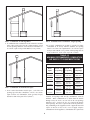
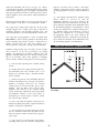
FIG. 16 Vent Termination from Peaked Roof - 10' or Less
From Ridge
(d) Place in operation the appliance being inspected.
Follow the lighting instructions. Adjust thermostat so
appliance will operate continuously.
(e) Test for spillage at the draft hood/relief opening
after five minutes of main burner operation. Use the
flame of a match or candle, or smoke from a cigarette,
cigar or pipe.
(f) After it has been determined that each appliance
remaining connected to the common venting system
12
FIG. 17 Vent Termination from Peaked Roof More Than
10' From Ridge
FIG. 19 Vent Termination from Flat Roof More Than 10'
from Parapet Wall
The vent terminal should be vertical and exhaust outside the
building at least 2 feet (0.61m) above the highest point of the
roof within a 10 foot (3.05m) radius of the termination.
A vertical termination less than 10 feet (3.05m) from a parapet
wall must be a minimum of 2 feet (0.61m) higher than the
parapet wall.
The vertical termination must be a minimum of 3 feet (0.91m)
above the point of exit.
The vent cap should have a minimum clearance of 4 feet
(1.22m) horizontally from and in no case above or below, unless
a 4 foot (1.22m) horizontal distance is maintained from electric
meters, gas meters, regulators and relief equipment.
The venting system shall terminate at least 3 feet (0.9m) above
any forced air inlet within 10 feet (3.05m).
The venting system shall terminate at least 4 feet (1.2m) below,
4 feet (1.2m) horizontally from, or 1 foot (30cm) above any
door, window or gravity air inlet into any building.
Do not terminate the vent in a window well, stairwell, alcove,
courtyard or other recessed area. The vent cannot terminate
below grade. The bottom of the vent terminal shall be located
at least 12 inches (30cm) above grade.
To avoid a blocked flue condition, keep the vent cap clear of
snow, ice, leaves, debris, etc. Flue gases will form a white
plume in winter. Plume could obstruct window view.
Flue gas condensate can freeze on exterior surfaces or on the
vent cap when a pool heater is operated in the winter months.
Frozen condensate on the vent cap can result in a blocked flue
condition. Flue gas condensate can cause discoloration of
exterior building surfaces. Adjacent brick or masonry surfaces
should be protected with a rust resistant sheet metal plate.
FIG. 18 Vent Termination from Flat Roof 10' or Less from
Parapet Wall
13
outlet and direct air inlet adapters are installed. No additional
draft diverter or barometric damper is required on single unit
installations with a dedicated stack and a negative draft
maintained between 0.02 to 0.08 inches water. The flue may be
combined with the vent from any other negative draft, Category
I appliances. Multiple unit installations common vented with
other negative draft appliances require that each pool heater
MUST have a barometric damper installed to regulate draft
within the proper range. The common vent and connectors from
multiple pool heaters must be sized per the requirements of the
venting tables for Type "B" double wall vents in the latest
edition of the National Fuel Gas Code, ANSI Z223.1 or in
Canada, CAN/CGA - B149 Installation Codes.
MASONRY CHIMNEY INSTALLATION
A masonry chimney must be properly sized for the installation
of a high efficiency gas fired appliance. Venting of a high
efficiency appliance into a cold or oversized masonry chimney
can result in operational and safety problems. Exterior masonry
chimneys, with one or more sides exposed to cold outdoor
temperatures, are more likely to have venting problems. The
temperature of the flue products from a high efficiency
appliance may not be able to sufficiently heat the masonry
structure of the chimney to generate proper draft. This will
result in condensing of flue products, damage the masonry
flue/tile, insufficient draft and possible spillage of flue products
into an occupied living space. Carefully inspect all chimney
systems before installation. If there is any doubt about the
sizing or condition of a masonry chimney, it must be relined
with a properly sized and approved chimney liner system.
The sidewall or vertical rooftop DirectAire combustion air
supply system has specific vent material and installation
requirements. The air inlet pipe connects directly to the pool
heater to supply combustion air. In most installations, the
combustion air inlet pipe will be a dedicated system with one air
inlet pipe per pool heater. Multiple air inlets for DirectAire
systems may be combined if the guidelines in "Combined Air
Inlet Points" are followed. The air inlet pipe will be connected
to a combustion air inlet cap as specified in this section.
Inspection of a Masonry Chimney
A masonry chimney must be carefully inspected to determine its
suitability for the venting of flue products. A clay tile lined
chimney must be structurally sound, straight and free of
misaligned tile, gaps between liner sections, missing sections of
liner or any signs of condensate drainage at the breaching or
clean out. If there is any doubt about the condition of a
masonry chimney, it must be relined. An unlined masonry
chimney must not be used to vent flue products from this high
efficiency appliance. An unlined chimney must be relined with
an approved chimney liner system when a new appliance is
being attached to it. Metallic liner systems (Type "B" doublewall or flexible or rigid metallic liners) are recommended.
Consult with local code officials to determine code
requirements or the advisability of using or relining a masonry
chimney.
Combustion air supplied from outdoors must be free of
contaminants (See Combustion and Ventilation Air).
The Vertical DirectAire Vent System
A CONVENTIONAL VERTICAL NEGATIVE
DRAFT VENTING
SYSTEM WITH A COMBUSTION
AIR PIPE FROM A SIDEWALL
OR ROOFTOP INLET CAP
FIG. 20 Vertical / Horizontal Installation Illustration
Follow all requirements in the General Venting section and
Conventional Negative Draft Venting for venting flue products
to the outdoors and general installation instructions.
Sidewall Air Inlet
The Vertical DirectAire vent system requires the installation of
two vent pipes directly to the unit, one vertical pipe with a roof
top termination for the flue products and one pipe for
combustion air. The combustion air pipe may terminate
horizontally with a sidewall air inlet or vertically with a rooftop
air inlet. Vent connection is made directly to the unit after the
outdoor vent cap assembly is removed and the conventional flue
The Sidewall Air Inlet Cap Kit is supplied as one of the
DirectAire Vent Kits which must be ordered from the
manufacturer. This sidewall cap will supply combustion air for
a single pool heater only.
14
Vertical Rooftop Air Inlet
The air inlet cap for the vertical roof top air inlet is supplied in
the Vertical DirectAire Roof Top Air Kit which must be
ordered from the manufacturer. This roof top cap will supply
combustion air for a single unit only.
FIG. 21 Air Inlet Cap for Sidewall Termination
Locate units as close as possible to sidewall where the
combustion air supply system will be installed.
To prevent recirculation of flue products from an adjacent vent
cap into the combustion air inlet, follow all applicable clearance
requirements in the latest edition of the National Fuel Gas Code
and instructions in this manual.
FIG. 23 Air Inlet Cap for Rooftop Termination
The point of termination for the combustion air inlet cap MUST
be at least 3 feet (0.91m) below the point of flue gas termination
(vent cap) if it is located within 10 feet (3.05m) of the flue
outlet.
The combustion air inlet cap must be installed at least one foot
(0.30m) above ground level and above normal snow levels.
The combustion air inlet cap must not be installed closer than
10 feet (3.05m) from an inside corner of an L-shaped structure.
The air inlet point for the combustion air inlet cap must be
installed at least one foot (0.30m) above the roof top and above
normal snow levels.
Incorrect installation and/or location of the air inlet cap can
allow the discharge of flue products to be drawn into the
combustion process on the pool heater. This can result in
incomplete combustion and potentially hazardous levels of
carbon monoxide in the flue products. This will cause
operational problems with the pool heater and possible spillage
of flue products which can cause personal injury, death or
property damage.
Combined Air Inlet Points
FIG. 22 Vertical DirectAire Installation with Rooftop
Combustion Air
The air inlet pipes from multiple pool heaters installed with the
DirectAire venting system can be combined to a single common
connection. The common air inlet pipe must have a cross
sectional area equal to or larger than the total area of all air inlet
pipes connected to the common air inlet pipe. [Example: two 5"
air inlet pipes (19.6 in2 area each) have a total area of 39.2 in2
15
and will require a single 8"(50.3 in2 area) common air inlet
pipe.] The air inlet point for multiple pool heater air inlets must
be provided with an exterior opening which has a free area
equal to or greater than the total area of all air inlet pipes
connected to the common air inlet. This exterior opening for
combustion air must connect directly to the outdoors. The total
length of the combined air inlet pipe must not exceed a
maximum of 50 (15.3m) equivalent feet. Subtract 5 feet
(1.52m) for each elbow in the air inlet pipe. You must deduct the
restriction in area provided by any screens, grills or louvers
installed in the common air inlet point. These are common on
the sidewall air inlet openings. Screens, grills or louvers
installed in the common air inlet can reduce the free area of the
opening from 25% (metal louvers) to 75% (wood louvers)
based on the materials used.
(c) Secure all joints with a minimum of three sheet
metal screws or pop rivets. Apply aluminum foil duct
tape or silicone sealant to all screws or rivets installed
in the air inlet pipe.
(d) Ensure that the air inlet pipe is properly supported.
CAUTION
Using other vent or air intake materials, failure to
properly seal all seams and joints or failure to follow
vent pipe manufacturer’s instructions can result in
personal injury, death or property damage. Mixing
of venting materials will void the warranty and
certification of the pool heater.
Air Inlet Pipe Materials
NOTE:
The use of double wall vent material for the
combustion air inlet pipe is recommended when the
pool heater is operated in cold climates to prevent
the condensation of airborne moisture in the
incoming combustion air.
The Vertical DirectAire system requires installation of a
separate pipe to supply combustion air from outdoors directly to
the unit. The following air inlet pipe materials and sealing
recommendations apply whenever an optional venting system
is used to duct combustion air directly to the pool heater.
Air Inlet Pipe Materials
Length of Air Inlet Pipe
The air inlet pipe(s) must be sealed. Choose acceptable
combustion air inlet pipe materials from the following specified
materials in this section.
The total equivalent length of the sidewall or vertical rooftop
DirectAire combustion air inlet pipe must not exceed a
maximum of 50 equivalent feet (15.3m) in length. Subtract 5
feet (1.52m) for each elbow in the air intake system. Do not
exceed limits for the combustion air inlet piping lengths.
PVC, CPVC or ABS (4"or 5" I.D.)*
Dryer Vent (not recommended for rooftop air inlet)
Vent Kits
Galvanized steel vent pipe with joints and seams
sealed as specified below.
The Vertical DirectAire Vent Kit for sidewall or rooftop air
inlet MUST be ordered from the pool heater manufacturer for
single unit installations. The part number for each kit is listed
by unit size. Each kit includes the flue outlet adapter air inlet
collar and in sidewall air kits, a sidewall combustion air inlet
cap to supply air to a single pool heater. Each kit includes
instructions for proper installation. The flue pipe, rooftop vent
cap for the flue, vertical air inlet cap and air inlet pipe are
purchased locally. You must specify if the air inlet cap is for a
vertical rooftop termination or a sidewall termination. The air
inlet cap for the combined air supply from multiple boilers must
be purchased locally.
Type "B" double wall vent with joints and seams
sealed as specified below.
* Plastic pipe requires an adapter (not provided) to
transition between the air inlet and cap.
Sealing of single wall galvanized or Type "B" double wall
vent material used for combustion air supply in a DirectAire
Vent System
(a) Seal all joints and seams of the air inlet pipe using
either Aluminum Foil Duct Tape meeting UL Standard
723 or 181A-P or a high quality UL Listed silicon
sealant such as those manufactured by Dow Corning or
General Electric.
(b) Do not install seams of air inlet pipe on the bottom
of horizontal runs.
16
TABLE - E
DIRECTAIRE VENT KITS
Input
Btu/hr
CAUTION
Pool heaters which are shut down or will not
operate may experience freezing due to convective
air flow in the air inlet pipe connected to the unit. If
operated in cold climates, continuous pump
operation is recommended to help prevent freezing
of pool water on DirectAire systems. Proper freeze
protection must be provided. A pool heater that is
not in use in the winter season must be properly
drained and winterized. See Freeze Protection.
Conventional Air Inlet Vert./Hor. Vertical
Air
Air
Vent Flue Size Pipe*
Inlet Kit Inlet Kit
150,000
5"
4"
VDK3020 VDK3017
199,999
5"
4"
VDK3020 VDK3017
250,000
5"
4"
VDK3020 VDK3017
300,000
5"
5"
VDK3021 VDK3018
The Powered Sidewall Venting System
6"
5"
399,999
VDK3022 VDK3019
*Minimum diameter, installer may increase diameter one pipe
size for ease of installation if needed.
POWERED SIDEWALL VENTING WITH
COMBUSTION AIR FROM
THE EQUIPMENT ROOM
CAUTION
The air inlet cap supplied in the Vertical DirectAire
Vent Kit is used to supply combustion air to a single
pool heater. The rooftop vent cap for flue products
should be a standard commercial cap purchased
locally. The use of a sidewall or rooftop air inlet cap
other than the manufacturers recommended cap for
single pool heater installations or use of a common air
inlet cap for multiple pool heaters with insufficient
free area and/or protection from wind and weather
may result in operational problems with the pool
heater or potentially hazardous spillage of flue
products which can cause personal injury, death or
property damage.
This venting system uses a powered vent assembly which pulls
the flue products from the pool heater and exhausts out a
sidewall. The fan in the powered vent cap generates a negative
draft at the unit. Combustion air is drawn from the equipment
room (see Combustion and Ventilation Air Requirements). The
outdoor vent cap must be removed and the optional Sidewall
Vent Kit must be installed. See Installation of Optional Vent
Kits.
Venting of Flue Products
For venting flue products vertically to the outdoors, follow all
requirements in the installation instructions for conventional
venting.
Termination point for the flue products must follow the
clearance requirements in the Vertical Vent Termination section
of Conventional Venting.
A barometric damper is NOT required in the flue on Vertical
DirectAire installations if the draft is within the 0.02 to 0.08
inches water negative required for proper operation. If the draft
exceeds this range, a barometric damper MUST be installed.
FIG. 24
Cap
Sidewall Venting Installation with Powered Vent
The sidewall fan is mounted in a vent cap which is installed on
an exterior wall. The sidewall fan and accessories are included
in a venting kit which must be furnished by the manufacturer in
accordance with CSA International requirements. This venting
kit includes a flue adapter, an air inlet cover, the sidewall
17
fan/cap, barometric damper, proving switch and all necessary
relays to interlock with the pool heater’s control system. A
barometric damper is required in the flue on Powered Sidewall
Venting installations. A barometric damper is supplied with
each Powered Sidewall Vent Kit and MUST be installed in the
flue of each unit. The barometric damper must be adjusted to
maintain a negative draft between 0.02 to 0.05 inches water
when the powered sidewall vent cap is operating. The
barometric damper controls draft and provides dilution air to the
vent system to prevent condensate formation. When a
barometric damper is installed, the equipment room must have
adequate air to supply dilution air to the barometric damper.
Sidewall Vent Pipe Requirements
The connection from the vent to the powered sidewall fan/cap
MUST be made with listed type "B" double wall (or equivalent)
vent and accessories. There shall be no reduction in vent size
from the units flue outlet to the inlet of the sidewall vent fan.
Vent pipe material must be supplied by the installer.
Follow all requirements in the General Venting and Sidewall
Vent Termination sections for venting flue products to the
outdoors. See the Combustion and Ventilation Air Requirements
section to insure that adequate combustion and ventilation air is
supplied to the mechanical room. All other general installation
requirements must be followed.
Length of Flue Pipe
The maximum total equivalent length of flue pipe connected to
the powered sidewall cap cannot exceed 75 equivalent feet
(22.9m). Subtract 5 feet (1.52m) for each elbow in the vent. Do
not exceed the limit for total equivalent vent pipe length.
Venting of Flue Products
Sidewall Vent Termination
The sidewall vent shall terminate at least 4 feet (1.22m) below,
4 feet (1.22m) horizontally from or 1 foot (0.30m) above any
door, window or gravity air inlet to the building.
The sidewall vent cap shall terminate at least 3 feet (0.91m)
above any forced air inlet within 10 feet (3.05m).
Do not terminate the sidewall vent in a window well, stairwell,
alcove courtyard or other recessed area. The sidewall vent
cannot terminate below grade.
The sidewall vent system shall terminate at least 1 foot (0.30m)
above grade, above normal snow levels and at least 7 feet (2.13m)
above grade when located adjacent to public walkways. The
sidewall vent shall not terminate directly above a public walkway.
The sidewall vent terminal shall not be installed closer than 10
feet (3.05m) from an inside corner of an L-shaped structure.
The sidewall vent cap should have a minimum clearance of 4
feet (1.22m) horizontally from and in no case above or below,
unless a 4 foot (1.22m) horizontal distance is maintained from
electric meters, gas meters, regulators and relief equipment.
FIG. 25 Powered Sidewall Vent Cap
The powered sidewall vent cap must be installed on an exterior
sidewall. The powered sidewall vent cap and accessories are
included in a venting kit which must be furnished by the
manufacturer in accordance with CSA International
requirements. This venting kit includes a flue adapter, an air
inlet cover, the powered sidewall cap, barometric damper,
proving switch and all necessary relays to interlock with the
heaters control system.
Flue gas condensate can freeze on exterior walls or on the vent
cap. Frozen condensate on the vent cap can result in a blocked
flue condition. Some discoloration to exterior building surfaces
can be expected. Adjacent brick or masonry surfaces should be
protected with a rust resistant sheet metal plate.
Powered Sidewall Vent Kits
The powered sidewall vent cap MUST be interlocked with the
pool heater’s control system to start the fan on a call for heat and
prove fan operation before the pool heater fires. Terminal strip
connections are provided on the unit for easy connection of the
factory supplied vent kit and control package for the sidewall
vent fan. See the installation instructions provided with the vent
kit.
The Powered Sidewall Vent Kit MUST be ordered from the
pool heater manufacturer. The part number for each kit is listed
by unit size. Each kit includes a flue adapter, an air inlet cover,
a powered sidewall fan/cap assembly, barometric damper,
control relay, proving switch and instructions for proper
installation. The outdoor vent kit, installed on the pool heater
as shipped from the factory, must be removed to install the
Powered Sidewall Vent Kit.
18
TABLE - F
POWERED SIDEWALL
VENT KITS
Input
Btu/hr
Flue
Size
Powered Sidewall
Kit
150,000
4"
SVK3031
199,999
4"
SVK3031
250,000
5"
SVK3032
300,000
5"
SVK3033
399,999
5"
SVK3033
POWER HORIZONTAL DIRECTAIRE WITH
A SIDEWALL FLUE AND
SIDEWALL AIR INLET
Follow all requirements in the General Venting section and
Sidewall Venting for venting flue products to the outdoors and
general installation instructions.
The Power Horizontal DirectAire vent system requires the
installation of two vent pipes directly to the pool heater, one
pipe for flue products and one for combustion air. Both vent
pipes are installed horizontally with a sidewall termination
point. Vent connection is made directly to the pool heater. Flue
products are carried to the sidewall by a powered sidewall
cap/fan assembly. A barometric damper is supplied with each
Horizontal DirectAire Vent Kit and MUST be installed in the
flue of each unit. The barometric damper must be adjusted to
maintain a negative draft between 0.02 to 0.05 inches water
when the powered sidewall vent cap is operating.
CAUTION
Pool heaters which are shut down or will not operate
may experience freezing due to convective air flow
into the equipment room. If operated in cold
climates, continuous pump operation is recommended
to help prevent freezing of pool water. Proper freeze
protection must be provided. A pool heater that is
not in use in the winter season must be properly
drained and winterized. See Freeze Protection.
The Power Horizontal DirectAire combustion air supply system
has specific vent material and installation requirements. The air
inlet pipe uses an adapter to connect directly to the pool heater
to supply combustion air. The combustion air inlet pipe will be
a dedicated system with one air inlet pipe per pool heater. The
air inlet pipe must be connected to a combustion air inlet cap as
specified in this section. Combustion air supply pipes for
multiple pool heater installations can NOT be combined into a
single pipe and inlet termination point.
The Powered Horizontal DirectAire Vent System
Combustion air supplied from outdoors must be free of
contaminants (See Combustion and Ventilation Air).
FIG. 26
Power Horizontal DirectAire Installation
Illustration
FIG. 27 Air Inlet Cap for Sidewall Termination
19
Sidewall Air Inlet
NOTE:
The use of double wall vent material for the
combustion air inlet pipe is recommended when the
pool heater is operated in cold climates to prevent
the condensation of airborne moisture in the
incoming combustion air.
The sidewall air inlet cap is supplied in the Power Horizontal
DirectAire Vent Kit which must be ordered from the
manufacturer. This sidewall cap will supply combustion air for
a single unit only.
Locate units as close as possible to sidewall where the
combustion air supply system will be installed.
Length of Air Inlet Pipe
To prevent recirculation of flue products from an adjacent vent
cap into the combustion air inlet, follow all applicable clearance
requirements in the latest edition of the National Fuel Gas Code
and instructions in this manual.
The total equivalent length of the Power Horizontal DirectAire
combustion air inlet pipe must not exceed a maximum of 75
(22.9m) equivalent feet in length. Subtract 5 feet (1.52m) for
each elbow in the air intake system. Do not exceed limits for
the combustion air inlet piping lengths.
The combustion air inlet cap must be installed at least one foot
(0.30m) above ground level and above normal snow levels.
Vent Kits
The point of termination for the combustion air inlet cap MUST
be at least 3 feet (0.91m) below the point of flue gas termination
(powered vent cap) if it is located within 10 feet (3.05m) of the
flue outlet from the powered vent cap. Use care to insure that the
air inlet cap assembly is properly installed on the air inlet pipe.
The combustion air inlet cap and the powered vent cap MUST
be installed on the same wall and in the same pressure zone.
The Power Horizontal DirectAire Vent Kit for sidewall
installation MUST be ordered from the pool heater
manufacturer. The part number for each kit is listed by unit
size. Each kit has a flue adapter, inlet air collar, sidewall
powered vent cap, barometric damper, proving switch,
controls, and combustion air inlet cap to supply air to a single
pool heater and instructions for proper installation. The flue
pipe and air inlet pipes are purchased locally.
The combustion air inlet cap must not be installed closer than
10 feet (3.05m) from an inside corner of an L-shaped structure.
TABLE - G
POWERED HORIZONTAL DIRECTAIRE
VENT KITS
Incorrect installation and/or location of the air inlet cap can
allow the discharge of flue products to be drawn into the
combustion process on the pool heater. This can result in
incomplete combustion and potentially hazardous levels of
carbon monoxide in the flue products. This will cause
operational problems with the pool heater and possible spillage
of flue products which can cause personal injury, death or
property damage.
Air Inlet Pipe Materials
The Power Horizontal DirectAire system requires installation of
a separate pipe to supply combustion air from outdoors directly
to the pool heater. See the air inlet pipe materials specified in
the DirectAire venting section for material requirements and
sealing recommendations for the air inlet pipe in a Horizontal
DirectAire system.
Input
Btu/hr
Flue
Size
150,000
4"
4"
SVK3034
199,999
4"
4"
SVK3034
250,000
5"
4"
SVK3035
300,000
5"
5"
SVK3036
399,999
5"
5"
SVK3036
DirectAire Power Horizontal
Inlet Pipe*
DirectAire Kit
*Minimum diameter, installer may increase diameter one pipe
size for ease of installation if needed.
WARNING
The sidewall air inlet cap supplied in the Power Horizontal
DirectAire Vent Kit is used to supply combustion air to a single
pool heater. Combustion air supply pipes from multiple units
can NOT be combined into a single air inlet pipe and inlet
point. The use of a sidewall air inlet cap other than the
manufacturers recommended cap may result in operational
problems with the boiler or potentially hazardous spillage of
flue products which can cause personal injury, death or property
damage.
Using other vent or air intake materials, failure to
properly seal all seams and joints or failure to follow
vent pipe manufacturer's instructions can result in
personal injury, death or property damage. Mixing
of venting materials will void the warranty and
certification of the pool heater.
20
flue to the vent cap and requires the use of a Category IV
stainless steel vent pipe with joints and seams fully sealed.
Combustion air must be drawn from the outside with a separate
combustion air pipe connected to the pool heater. The outdoor
vent cap must be removed and the optional E-Rite Sidewall Vent
Kit must be installed. See Installation of Optional Vent Kits.
Venting of Flue Products
For venting flue products horizontally to the outdoors, follow
all requirements in the installation instructions for sidewall
venting.
Termination point for the flue products must follow the
clearance requirements in the Sidewall Vent Termination
section of Sidewall Venting.
The air shutter on the combustion air fan MUST be adjusted
when the E-Rite Sidewall Vent Kit is installed. Use a rule to
measure the distance from the base of the fan to the end of the air
shutter. Follow the steps below to adjust the fan air shutter.
Compare this distance to the specified "A" dimension for the unit.
A barometric damper is required in the flue on Power
Horizontal DirectAire installations. The barometric damper
must be adjusted to maintain the draft within the 0.02 to 0.05
inches water negative required for proper operation. The
barometric damper provides dilution air to the vent system to
prevent condensate formation.
1. Turn the power switch to the "OFF" position.
2. Turn the gas valve switch to the "OFF" position
3. Remove upper front access door.
CAUTION
4. Use a ruler or the spacer supplied in the vent kit to
measure the distance from the base of the fan to the end
of the air shutter. Compare this distance to the specified
"A" dimension for the E-Rite Sidewall Vent System.
Pool heaters which are shut down or will not operate
may experience freezing due to convective air flow in
the air inlet pipe connected to the unit. If operated in
cold climates, continuous pump operation is
recommended to help prevent freezing of pool water
on DirectAire systems. Proper freeze protection
must be provided. A pool heater that is not in use in
the winter season must be properly drained and
winterized. See Freeze Protection.
TABLE - H
AIR SHUTTER ADJUSTMENT OPENING
FOR E-Rite VENT SYSTEMS
Input
Btu/hr
“A” Dimension
Opening
Chamber
Pressure
150,000
1 1/4"
1.4"
199,999
1 1/4"
1.3"
250,000
1 3/8"
1.3"
300,000
1 9/16"
1.3"
399,999
1 3/4"
1.3"
E-RITE SIDEWALL VENTING SYSTEM
FIG. 28 E-Rite Sidewall Vent Installation
"A"
This venting system uses the internal combustion air fan to
force the flue products out of a sealed vent pipe to a sidewall
vent cap assembly. The fan generates a positive pressure in the
FIG. 29 Combustion Air Fan with Air Shutter "A" Dimension
21
The E-Rite Sidewall combustion air supply system has specific
vent material and installation requirements. The air inlet pipe
connects directly to the pool heater to supply combustion air.
The combustion air inlet pipe will be a dedicated system with
one air inlet pipe per pool heater. The air inlet pipe, its
connection and location of the combustion air inlet cap will be
the same as specified in the Horizontal DirectAire Vent
Systems.
TABLE - I
E-RITE SIDEWALL VENT KITS
Combustion air supplied from outdoors must be free of
contaminants (See Combustion and Ventilation Air).
Input
Btu/hr
Inlet & Outlet
Vent Diameter
E-Rite Sidewall
Vent Kit
150,000
4"
HDK3024
199,999
4"
HDK3024
250,000
4"
HDK3024
300,000
5"
HDK3025
399,999
5"
HDK3025
The flue pipe from the flue outlet on the side of the pool heater
to the sidewall vent cap is under a positive pressure and must
use a totally sealed Category IV vent pipe.
E-Rite Sidewall Vent Pipe Requirements
The connection from the vent to the sidewall cap MUST be
made with listed Category IV vent material and accessories.
There shall be no reduction in vent size from the pool heater's
flue outlet to the inlet of the sidewall vent cap. Vent pipe
material may be purchased locally by the installer.
AIR INLET CAP
Flue Pipe Materials
FLUE OUTLET CAP
Select venting material from the following specified vent
materials:
FIG. 30 E-Rite Sidewall Vent Caps Illustration
E-Rite Sidewall Vent Cap for 150,000 through
399,999 Btu/hr Models
Protech Systems Inc. Fas N Seal Vent with AL29-4C
stainless steel
(Call 1-800-766-3473 for nearest distributor)
The E-Rite Sidewall vent caps must be installed on an exterior
sidewall. The E-Rite Sidewall vent cap and accessories are
included in a venting kit which must be furnished by the
manufacturer in accordance with CSA International
requirements. This venting kit includes a flue adapter, air inlet
collar, sidewall vent cap, air inlet cap and necessary adapters to
install a separate combustion air pipe from the pool heater to the
outdoors.
Z-Flex Z-Vent with AL29-4C stainless steel
(Call 1-800-654-5600 for nearest distributor)
Heat-Fab Inc. Saf-T CI Vent with AL29-4C stainless
steel (Call 1-800-772-0739 for nearest distributor)
Flex-L International Inc. StaR 34 Vent with AL29-4C
stainless steel
(Call 1-800-561-1980 for nearest distributor)
The factory supplied sidewall vent kit MUST be used for
sidewall venting installation.
Metal-Fab Inc. Corr/Guard Vent with AL29-4C
stainless steel
(Call 1-800-835-2830 for nearest distributor)
E-Rite Sidewall Vent Kits
The E-Rite Sidewall Vent Kit MUST be ordered from the pool
heater manufacturer. The part number for each kit is listed by
unit size. Each venting kit includes the sidewall caps, necessary
adapters to install a separate combustion air pipe from the pool
heater to the outdoors and instructions for proper installation.
Or other listed Category IV vent systems suitable for
a positive pressure gas fired appliance.
22
(d) Ensure that the air inlet pipes are properly
supported.
Air Inlet Pipe Materials
The E-Rite Sidewall Vent system requires installation of a
separate pipe to supply combustion air from outdoors directly to
the pool heater. See the air inlet pipe materials specified in the
DirectAire venting section for material requirements and
sealing recommendations for the air inlet pipe on an E-Rite
Sidewall Vent system.
The PVC, CPVC or ABS air inlet pipe should be cleaned and
sealed with the pipe manufacturers recommended solvents and
standard commercial pipe cement for the material used. The
PVC, CPVC, ABS or Dryer Vent air inlet pipe should use a
silicone sealant to insure a proper seal at the pool heater
connection and the air inlet cap connection. Dryer vent should
use a screw type clamp to seal the vent to the boiler and air inlet
cap. Proper sealing of the air inlet pipe insures that combustion
air will be free of contaminants and supplied in proper volume.
NOTE
The use of double wall vent material for the
combustion air inlet pipe is recommended when the
pool heater is operated in cold climates to prevent
the condensation of airborne moisture in the
incoming combustion air.
Sealing of vent material for use with the E-Rite
Sidewall Vent System
The vent materials, Heat-Fab Saf-T CI Vent, Z-Flex Z-Vent,
Protech Systems Fas N Seal Vent, Flex-L Star-34 Vent, MetalFab Corr/Guard Vent or listed AL29-4C vent systesm suitable
for positive pressure, must be installed and sealed per the vent
manufacturers installation instructions.
WARNING
Using other vent or air intake materials, failure to
properly seal all seams and joints or failure to follow
vent pipe installation instructions can result in
personal injury, death or property damage.
Improper sealing of venting materials will void the
warranty and certification of the pool heater.
Length of Flue Pipe and Air Inlet Pipe for an E-Rite
Sidewall Vent System
The maximum total equivalent length of the sidewall flue or the
sidewall combustion air inlet pipe must not exceed a maximum
of 20 equivalent feet (6.1m) in length. Subtract 5 feet (1.52m)
for each elbow in the flue pipe or the air intake system. The
transition adapter mounted to the flue outlet on the pool heater
does not count as one of the elbows in the venting system. Do
not exceed limits for the combustion air inlet and flue outlet
piping lengths.
Sealing of Type "B" double wall vent material or galvanized
vent pipe material used for air inlet pipe on a E-Rite
Sidewall Vent System:
TO SUITABLE DRAIN
FIG. 31 Drain Tee Installation
(a) Seal all joints and seams of the air inlet pipe using
either Aluminum Foil Duct Tape meeting UL Standard
723 or 181A-P or a high quality UL Listed silicon
sealant such as those manufactured by Dow Corning
or General Electric.
Drain Tee Installation
A drain tee must be installed in the vent pipe to collect and
dispose of any condensate that may occur in the vent system.
The drain tee must be installed as the first fitting after the
horizontal ell on the top of the unit. See the typical vent
installation drawings. Plastic drain tubing, sized per the vent
manufacturers instructions, shall be provided as a drain line
from the tee. The drain tubing must have a trap provided by a
3" (7.6cm) diameter circular trap loop in the drain tubing.
Prime the trap loop by pouring a small quantity of water into the
drain hose before assembly to the vent. Secure the trap loop in
position with nylon wire ties. Use caution not to collapse or
restrict the condensate drain line with the nylon wire ties. The
(b) Do not install seams of vent pipe on the bottom of
horizontal runs.
(c) Secure all joints with a minimum of three sheet
metal screws or pop rivets. Apply aluminum foil duct
tape or silicone sealant to all screws or rivets installed
in the vent pipe.
23
condensate drain must be routed to a suitable drain for disposal
of condensate that may occur in the direct vent system. Refer
to the condensate drain installation instructions as supplied by
the manufacturer of the vent material.
The sidewall vent system shall terminate at least 1 foot (0.30m)
above grade, above normal snow levels and at least 7 feet
(2.13m) above grade when located adjacent to public walkways.
The sidewall vent shall not terminate directly above a public
walkway.
When an E-Rite Sidewall vent system is disconnected for any
reason, the flue must be reassembled and resealed according to
the vent manufacturers instructions to insure that flue products
will not be discharged into the equipment room or other
occupied spaces in the building. The air inlet pipe must also be
resealed to insure that combustion air will be free of
contaminants and supplied in proper volume.
The sidewall vent terminal shall not be installed closer than 10
feet (3.05m) from an inside corner of an L-shaped structure.
The sidewall vent cap should have a minimum clearance of 4
feet (1.22m) horizontally from and in no case above or below,
unless a 4 foot (1.22m) horizontal distance is maintained from
electric meters, gas meters, regulators nd relief equipment.
The connection from the vent to the vent termination outside the
building MUST be made with one of the specified vent materials
and must be direct as possible with no reduction in diameter. The
vent accessories not otherwise provided, such as firestop spacers,
thimbles, caps, etc., MUST be from the same vent material
manufacturer and installed in accordance with the manufacturers
listing. The vent connection through the sidewall must provide
correct spacing to combustible surfaces. The vent pipe
connection to the sidewall vent cap MUST have a gas-tight seal
to prevent the leakage of flue products.
Flue gas condensate can freeze on exterior walls or on the vent
cap. Frozen condensate on the vent cap can result in a blocked
flue condition. Some discoloration to exterior building surfaces
can be expected. Adjacent brick or masonry surfaces should be
protected with a rust resistant sheet metal plate.
Combustion Air Inlet
Combustion air supply pipes can NOT be combined into a
single pipe for multiple unit installations.
Installation of an E-Rite Sidewall Vent System requires that
each pool heater in a multiple unit installation have a dedicated
flue pipe and sidewall vent cap. The flue discharge or air inlet
from multiple pool heaters installed with the E-Rite Sidewall
Vent System may NOT be combined to a single common vent.
Combustion air supplied from outdoors must be free of
contaminants (See Combustion and Ventilation Air). To prevent
recirculation of flue products into the combustion air inlet,
follow all instructions in this section.
DANGER
To help prevent recirculation of flue products:
Failure to properly seal all joints and seams as
required in the flue piping may result in flue gas
recirculation, spillage of flue products and carbon
monoxide emissions causing severe personal injury
or death.
The combustion air inlet cap MUST NOT be installed above
the flue outlet cap.
Follow all requirements in the General Venting and Sidewall
Vent Terminations sections for venting flue products to the
outdoors. See the Combustion and Ventilation Air
Requirements section to insure that adequate combustion and
ventilation air is supplied to the mechanical room. All other
general installation requirements must be followed.
The combustion air inlet cap and vent cap for flue outlet MUST
be located on the same sidewall and in the same pressure zone.
The combustion air inlet cap must be installed horizontally or
below the flue outlet and MUST maintain a minimum 3 foot
(0.91m) radius clearance from the flue outlet cap.
The combustion air inlet cap must not be installed closer than
10 feet (3.05m) from an inside corner of an L-shaped structure.
The combustion air inlet cap must be installed at least one foot
(0.30m) above ground level and above normal snow levels.
E-Rite Sidewall Vent Termination
The sidewall vent cap shall terminate at least 3 feet (0.91m)
above any forced air inlet within 10 feet (3.05m).
The sidewall vent shall terminate at least 4 feet (1.22m) below,
4 feet (1.22m) horizontally from or 1 foot (0.30m) above any
door, window or gravity air inlet to the building.
Do not terminate the sidewall vent in a window well, stairwell,
alcove courtyard or other recessed area, The sidewall vent can
not terminate below grade.
24
Multiple E-Rite Sidewall Vent Installations
TABLE - J
INLET GAS PRESSURE
3' MIN.
Measured at the inlet pressure tap located
upstream of the combination gas valve.
Nat.
Gas
LPG
150,000 - 399,999 Btu/hr
Max. (Inches-Water Column)
10.5" w.c.
13" w.c.
150,000 - 300,000 Btu/hr
Min. (Inches-Water Column)
4.5" w.c.
4.5" w.c.
399,999 Btu/hr
Min. (Inches-Water Column)
5.0" w.c.
5.0" w.c.
Btu/hr Input
3' MIN.
FIG. 32 Installation of Multiple E-Rite Sidewall Vent Caps
Maximum inlet gas pressure must not exceed the value specified.
Minimum value listed is for the purposes of input adjustment.
The combustion air inlet caps for multiple unit installations
must maintain the minimum 3 foot (0.91m) radius clearance
below or horizontally from the closest flue outlet. Multiple flue
outlet caps may be installed side by side and multiple air inlet
caps may be installed side by side but the 3 foot (0.91m) radius
minimum clearance between air inlet and flue outlet must be
maintained. All clearance and installation requirements in this
section and the applicable portions of the general venting
section must be maintained on multiple unit installations.
MANIFOLD PRESSURE: Measured at the pressure tap on
the downstream side of the combination gas valve. If
adjustment of regulator pressure is required, see Manifold
Adjustment Procedure. Do not increase regulator pressure
beyond specified pressure setting.
TABLE - K
NET MANIFOLD PRESSURE
CAUTION
Pool heaters which are shut down or will not operate
may experience freezing due to convective air flow in
the flue pipe or from negative pressure in the
equipment room. If operated in cold climates,
continuous pump operation is recommended to help
prevent freezing of pool water. Proper freeze
protection must be provided. A pool heater that is
not in use in the winter season must be properly
drained and winterized. See Freeze Protection.
Btu/hr Input
Natural and LP Gas
Regulator Setting
150,000 - 399,999
1.8” w.c. Net for the
Referenced gas valve
GAS PRESSURE TEST
1. The pool heater and its individual shutoff valve must be
disconnected from the gas supply piping system during any
pressure testing of that system at a test pressure in excess of
1/2 PSIG (3.5kPa).
GAS SUPPLY
Verify unit is supplied with the type gas specified on the rating
plate. This unit is orificed for operation up to 2000 feet altitude.
Consult factory for installations above 2000 feet elevation.
2. The pool heater must be isolated from the gas supply piping
system by closing its individual manual shutoff valve during
any pressure testing of the gas supply piping system at test
pressures equal to or less than 1/2 PSIG (3.5kPa).
3. The pool heater and its gas connection must be leak-tested
before placing the heater in operation.
GAS CONNECTION
Safe operation of the unit requires properly sized gas supply
piping. See the following data:
25
1. Gas pipe size may be larger than heater connection.
TABLE - M
FITTINGS TO EQUIVALENT STRAIGHT
PIPE
2. Installation of a union is highly recommended for ease of
service. Install union as close as possible to gas valve inlet.
Diameter
Pipe
3/4"
(inches)
Equivalent
length of
Straight Pipe
2'
(feet)
3. Install a manual main gas shutoff valve, outside of the appliance
gas connection and before the gas valve, when local codes require.
4. A trap (drip leg) MUST be provided in the inlet of the gas
connection to the unit.
5. The combination gas valve has an integral vent limiting device
and does not require venting to atmosphere, outside the building.
6. Optional gas controls may require routing of bleeds and vents
to the atmosphere, outside the building when required by local
codes.
1"
2'
1 1/4" 1 1/2" 2"
3'
4'
5'
3"
4"
5"
10' 14' 20'
LP GAS INSTALLATIONS
WARNING
TABLE - L
LOW PRESSURE NATURAL GAS
SINGLE UNIT INSTALLATIONS
SUGGESTED GAS PIPE SIZE
LP (propane) gas is heavier than air and will remain at
floor level if there is a leak. Basements, crawl spaces,
alcoves, and areas below ground level will serve as pockets
for accumulation of leaking gas. Before lighting, sniff at
floor level. IF YOU SMELL GAS, follow instructions on
PAGE ONE of INSTALLATION & SERVICE MANUAL.
Shut off gas at LP tank outside of building. DO NOT
OPERATE APPLIANCE UNTIL LEAKAGE IS
CORRECTED.
DISTANCE FROM METER
Input
Btu/hr
0-50’
51’100’
101’200’
201’300’
301’500’
150,000
3/4"
1"
1 1/4"
1 1/4"
1 1/2"
199,999
1"
1"
1 1/4"
1 1/2"
2"
250,000
1"
1 1/4"
1 1/2"
1 1/2"
2"
300,000
1 1/4"
1 1/4"
1 1/2"
1 1/2"
2"
399,999
1 1/4"
1 1/4"
1 1/2"
2"
2"
LP gas cylinders shall be located outdoors and away from the
pool structure in accordance with the latest edition of the
Standard for the Storage and Handling of Liquefied Petroleum
Gases, ANSI/NFPA 58, or CAN/CSA B149.2, and applicable
local codes.
For each elbow or tee, add equivalent straight pipe to total
length from Table N.
TABLE - N
MULTIPLE UNIT INSTALLATIONS GAS PIPING SIZE CHART
226
26
Maximum Capacity of
Pipe in Thousands of
Btu/hr per hour for gas
pressures of 14 Inches
Water Column (0.5
PSIG) or less and a
pressure drop of 0.5
Inch Water Column
(Based on NAT GAS,
1025 Btu/hr per Cubic
Foot of Gas and 0.60
Specific Gravity)
All gas connections must be made with pipe joint compound
resistant to the action of liquefied petroleum and natural gasses. All
piping must comply with local codes and ordinances. Tubing
installations must comply with approved standards and practices.
TABLE - O
SINGLE OR SECOND STAGE
LOW PRESSURE
PROPANE GAS PIPING
SINGLE UNIT INSTALLATIONS
SUGGESTED GAS PIPE SIZE
Install Piping to Control
1. The gas line should be a separate line direct from the meter
unless the existing gas line is of sufficient capacity. Verify
pipe size with your gas supplier.
DISTANCE FROM METER
Input
Btu/hr
0-50'
51'-100'
150,000
3/4"
1"
1"
1"
199,999
3/4"
1"
1"
1 1/4"
250,000
1"
1"
1 1/4"
1 1/4"
300,000
1"
1 1/4"
1 1/4"
1 1/2"
2. Use new, properly threaded black iron pipe free from chips. If
tubing is used, make sure the ends are square, deburred and
clean. All tubing bends must be smooth and without
deformation. Avoid flexible gas connections. Internal diameter
of flexible lines may not provide unit with proper volume of gas.
101'-200' 201’-300'
3. Install a manual main gas shutoff valve at the pool heater's
gas inlet, outside of the pool heater and before the gas valve.
When the pool heater is installed in, under or directly
attached to the pool or spa structure, the manual main gas
shutoff valve must be located outside the pool structure.
399,999
1"
1 1/4"
1 1/4"
1 1/2"
For each elbow or tee, add equivalent straight pipe to total
length from Table N.
4. Run pipe or tubing to the pool heater's gas inlet. If tubing is
used, obtain a tube to pipe coupling in order to connect the
tubing to the pool heater's gas inlet.
TABLE - P
FIRST STAGE
HIGH PRESSURE PROPANE
GAS PIPING
SINGLE UNIT INSTALLATIONS
SUGGESTED GAS PIPE SIZE
Length
Tubing Size
0 - 70 Feet
1/2” Copper Tubing
5. Install a sediment trap in the supply line to the pool heater's
gas inlet (see Figure 33).
6. Apply a moderate amount of good quality pipe compound (DO
NOT use Teflon tape) to pipe only, leaving two end threads bare.
7. Remove seal over gas inlet to pool heater.
71 - 250 Feet
5/8” Copper Tubing
Capacity based on 5 PSIG inlet with 1 PSIG pressure drop.
GAS PIPING
FIG. 34 Wrench to Support Gas Valve for Piping Connection
8. Connect gas pipe to inlet of unit. Use a wrench to support
the gas manifold on the unit.
FIG. 33 Gas Line Connection to unit w/sediment trap and
manual main gas shut-off valve
27
(b) Locate the air pressure switch located to the right
of the combustion air fan. Trace the hose from the air
pressure switch to the barb located in the top right
front corner of the upper chamber. Remove the hose
from this barb and connect the hose from the
manometer or magnahelic to this barb to measure the
air pressure in the front chamber.
9. For LP gas, consult your LP gas supplier for expert
installation.
10. Ensure that all air is properly bled from the gas line before
starting the ignition sequence. Start up without properly
bleeding air from the gas line may require multiple reset
functions of the ignition control module to achieve proper
ignition.
(c) Turn the power switch to the "ON" position.
(d) Ensure that the "ON/OFF" switch on the smart
valve is in the "ON" position.
GAS MANIFOLD PRESSURE
ADJUSTMENT PROCEDURE
(e) Set the electronic temperature control to call for
heat. The fan should start.
IMPORTANT:
(f) While the combustion air fan is running for the
pre-purge cycle and the pressure in the front chamber
stabilizes, record the pressure in the front chamber.
This pressure will be used to calculate the net manifold
pressure.
The gas valve is referenced to the fan pressurized
chamber by a hose connected from the vent of the
gas valve regulator to the chamber pressure tap
located on the front inside portion of the jacket.
Reference the drawings in this section for component
location and connection points for pressure
measurement. The referenced chamber pressure
must be subtracted from the manifold pressure to
obtain actual net manifold pressure for normal
operation. A manometer or magnahelic gauge
legible in 0.1" increments up to 10" water column is
required to check and adjust the manifold pressure.
The regulator cover screw on the gas valve must be
in place and tight for the appliance to operate
properly.
(g) Turn the power switch to the "OFF" position.
(h) Remove the manometer or magnahelic hose from
the front chamber barb and reinstall the hose from the
air pressure switch to the barb.
(i) Turn the manual gas cock to the "OFF" position.
Regulator Adjustment
1. Turn the power switch to the "OFF" position.
(a) Remove the top front jacket panels.
FIG. 36 Manifold Gas Pressure Measurement
(j) Remove the 1/8" hex plug, located on "outlet" side
of the gas valve and install a fitting suitable to connect
to a manometer or magnahelic gauge.
Minimum
range of scale should be up to 5" w.c. for natural gas
and LP gas.
FIG. 35 Front Chamber Pressure Measurement
28
(k) A reference pressure hose is factory installed from
the barbed connection on the gas valve regulator to the
fan pressurized front chamber. All manifold pressure
measurements made with the reference hose in place
will be the sum of the net manifold pressure and the air
pressure in the front chamber.
NOTE:
The front chamber pressure must be subtracted from
the gross regulator pressure to obtain actual net
manifold pressure for normal operation. The front
chamber pressure may vary based on elevation, vent
length and model. For information on chamber
pressure, see Combustion Air Adjustment.
(l) Turn the power switch to the "ON" position.
(m) Ensure that the "ON/OFF" switch on the smart
valve is in the "ON" position.
Do not increase net manifold pressure beyond the specified
pressure setting.
(n) Turn the manual gas cock to the "ON" position.
If adjustment is necessary, remove the regulator cover screw on
the gas valve.
(o) Set the electronic temperature control to call for heat.
(r) Turn regulator adjustment screw clockwise to raise
regulator gas pressure, counter clockwise to lower the
regulator gas pressure. Turn regulator adjustment
screw ¼ turn in the desired rotation and cycle the
burners on in the sequence listed below and record the
observed chamber and regulator settings. Subtract to
determine the net manifold pressure setting. Repeat as
necessary to achieve the specified net manifold
pressure setting.
(p) Before the valve opens, the manometer or
magnahelic gauge will read a positive air pressure of
1.3" w.c. to 1.5" w.c. in the jacket as supplied by the
combustion air fan on high speed in the pre-purge
cycle. There is no gas flow at this point. This air
pressure reading is normal.
(q) The gas valve will open at the end of the trial for
ignition stage and remain open as the burners fire.
Observe the gas manifold pressure when the valves
open. If insufficient gas pressure is supplied to the
burners, the burners will not fire. Record the gas
pressure indicated on the manometer or magnahelic.
Subtract the air pressure in the front chamber (as
recorded in step 7) from the gross manifold pressure
observed at the end of trial for ignition and when the
burners are firing. The gross manifold pressure will
typically be within the range of 3.1" w.c to 3.5" w.c.
for Natural Gas and LP Gas. The difference in the
gross manifold pressure and the front chamber
pressure is the net manifold pressure setting of the gas
valve's regulator. Compare the net setting to the
setting specified for the type of gas used. Adjust the
regulator as required. Set the electronic temperature
control or thermostat to a setting lower than the unit's
water temperature to turn the burners off. Allow unit
to run through the post purge sequence. Turn the
power switch to the "OFF" position.
(s) Replace cover screw on the regulator and turn the
power switch to the "ON" position. Set the electronic
temperature control or thermostat to call for heat.
Observe gas regulator pressure again at the burner
"ON" stages. Repeat this sequence until the proper
regulator setting has been obtained.
NOTE:
If the regulator cover screw is not in place and tight,
the unit will not function properly.
(t) Turn the power switch to the "OFF" position.
(u) Turn manual gas cock knob to the "OFF" position.
(v) Remove the gas pressure fitting from the gas valve
and replace with the 1/8" hex plug (that was previously
removed) and tighten.
Net Manifold Pressure = Regulator Pressure Less Front
Chamber Pressure:
Type of Gas
Net Manifold Pressure Setting
Natural Gas or LP Gas
1.8" w.c.
(w) Ensure that the chamber pressure reference hose
is properly connected to the gas valve.
(x) Turn the manual gas cock to the "ON" position.
(y) Turn the power switch to the "ON" position and
replace the jacket panels. The appliance is now ready
to operate.
If manifold pressure can not be properly maintained, check gas
supply pressure with a manometer connected to the inlet
pressure tap on the gas control.
29
supplier, qualified installer or service agency to determine
necessary steps to provide proper gas pressure to the control.
CHECKING GAS SUPPLY PRESSURE
1. Turn the main power switch to the "OFF" position.
10. If gas supply pressure is within normal range, proceed to
remove gas manometer and replace pressure tap fittings in
the gas control.
2. Shut off gas supply at the field installed manual gas cock in
the gas piping to the appliance. If fuel supply is LP gas, shut
off gas supply at the tank.
11. Turn the power switch to the "OFF" position.
12. Shut off gas supply at the manual gas cock in the gas piping
to the appliance. If fuel supply is LP gas, shut off gas supply
at the tank.
Supply Pressure Measurement
13. Remove the manometer and related fittings from "inlet" side
of the gas valve, replace 1/8" hex plug in gas valve and
tighten.
14. Turn on gas supply at the manual valve, turn on LP gas at
tank if required.
15. Turn the power switch to the "ON" position.
16. Ensure that the "ON/OFF" switch on the smart valve is in
the "ON" position..
17. Set the electronic temperature control or thermostat to call
for heat.
If proper ignition and burner operation is not achieved after
checking gas supply pressure and setting the correct net
manifold pressure, see the Maintenance section for Combustion
Air Adjustment. Follow the procedure to adjust the combustion
air fan.
FIG. 37 Gas Supply Pressure Measurement at Combination
Gas Valve
3. Remove the 1/8" hex plug, located on "inlet" side of the gas
valve. An inlet pressure tapping is located on the top side of
the valve body. A tapping on the field installed main
manual gas cock may also be used. Install a fitting in the
inlet pressure tapping suitable to connect to a manometer or
magnahelic gauge. Range of scale should be 14" w.c. or
greater to check inlet pressure.
IMPORTANT:
Upon completion of any testing on the gas system,
leak test all gas connections with a soap and water
solution while main burners are operating. Do not
spray soap and water solution on the SmartValve
housing. The use of an excessive amount of soap and
water solution can damage the control. Immediately
repair any leak found in the gas train or related
components. Do Not operate an appliance with a
leak in the gas train, valves or related piping.
4. Turn on gas supply at the manual gas cock, turn on LP gas at
tank if required.
5. Turn the power switch to the "ON" position.
Check burner performance by cycling the system while you
observe burner response. Burners should ignite promptly.
Flame pattern should be stable, see "Maintenance-Normal
Flame Pattern." Turn system off and allow burners to cool, then
cycle burners again to insure proper ignition and flame
characteristics.
6. Ensure that the "ON/OFF" switch on the smart valve is in the
"ON" position.
7. Set the electronic temperature control to call for heat.
8. Observe the gas supply pressure as all burners are firing.
Ensure that inlet pressure is within the specified range.
Minimum and Maximum gas supply pressures are specified
in the Gas Supply Section.
WATER CONNECTIONS
This pool heater is equipped with an automatic, built-in bypass
located in the front header. This bypass is flow actuated to
9. If gas pressure is out of range, contact gas utility, gas
30
maintain proper flow through the pool heater at flow rates of
less than 100 GPM. If the water flow rate to the pool heater
exceeds 100 GPM, an auxiliary bypass MUST be installed in
the piping to the pool heater. See auxiliary bypass section for
piping and adjustment.
TABLE - Q
MINIMUM WATER FLOW REQUIREMENTS
Minimum water flow rates to insure
proper operation are as follows:
Input Btu/hr
Minimum Flow
150,000
15 GPM
199,999
20 GPM
250,000
25 GPM
300,000
30 GPM
399,999
40 GPM
FIG. 39 Alternate Piping Connections
NOTE:
The pool heater installation may require a 3/4” drain
pipe. Check with your local code authorities. In
these applications, install a 3/4” threaded connection
in the piping, located immediately downstream of the
inlet/outlet connection on the front header for system
drainage.
A metallic pipe heat sink is not required on pool heater
installation. PVC, CPVC or other high temperature plastic
piping may be used to pipe directly to the pool heater if
permitted by local codes. When the pool heater is used with a
spa or therapy pool, CPVC or metallic pipe is recommended. A
silicon type sealant with a high elasticity must be used at
flanged connections to prevent leakage. This helps to
compensate for the large differences in expansion and
contraction of the materials used in piping and the flanged
connections. The filtration pump must operate simultaneously
when the heater is in service to ensure that there is no damage
to PVC piping connected directly to the pool heater. A check
valve should be installed in the piping to the heater if there is
the possibility of "back siphoning" when the pump stops.
AUXILIARY BYPASS
FIG. 38 Typical Piping for Water Connections
When water flow rates to the pool heater exceed 100 GPM, a
portion of this high water flow MUST be diverted with an
external bypass. High performance pumps can provide flows in
excess of 100 GPM. An auxiliary bypass as shown in the
attached drawing MUST be installed when the maximum flow
is exceeded. The bypass must have a valve installed between
the connections to the pool heater to allow a portion of the
excess flow to be diverted to the pool. The bypass allows the
proper volume of water to be supplied to the pool heater to
prevent sweating and condensate. The bypassed water prevents
needless pressure drop and reduction in flow rates.
Inlet and Outlet Connections
Connection to the pool heater can be made with either 2"
threaded pipe or a slip connection with 1 1/2" or 2" pipe. Two
inch threaded pipe may be directly screwed into the flanged
header connections for both inlet and outlet piping. Each pool
heater is supplied with two sets of gaskets to allow a flanged
compression attachment of either 2" or 1 1/2" copper pipe
directly to the front header. Ensure that the correct gasket is
used to match the pipe diameter used. Minimum pipe size for
installation of the pool heater is 1 1/2" diameter.
31
IMPORTANT:
High chemical concentrations from improperly
adjusted feeders and chlorinators can cause rapid
corrosion to the heat exchanger. This damage is nonwarrantable.
RELIEF VALVE
An optional temperature and pressure relief valve may be field
installed in the front header if required by local codes. Open the
upper side jacket panel above the water connections to access
the mounting point. Remove the 3/4" NPT plug in the outlet
side of the front header to install the relief valve. The relief
valve should be properly sized based on local code
requirements. In the absence of local code requirements, the
relief valve should be sized in accordance with ASME Boiler
and Pressure Vessel Code, Section IV ("Heating Boilers"). The
relief valve is installed in the vertical position and mounted in
the front header on the hot water outlet of the pool heater.
Remove the plug from the rear jacket panel to route the
discharge pipe to the outside of the jacket. Water damage to the
controls may occur if discharge piping is not properly installed
to route relief valve discharge water to the exterior of the jacket.
No valve is to be placed between the relief valve, and the unit.
To prevent water damage, the discharge from the relief valve
shall be piped to a suitable floor drain for disposal when relief
occurs. No reducing couplings or other restrictions shall be
installed in the discharge line. The discharge line shall allow
complete drainage of the valve and line. Relief valves should
be manually operated at least once a year.
FIG. 40 Auxiliary Bypass Piping
ADJUSTMENT OF
AUXILIARY BYPASS
1. Backwash and clean pool filters.
2. Start with bypass valve in half open position.
3. Start the pool heater.
4. Check the temperature of the outlet piping from the pool
heater. It should be slightly warm to the touch.
5. If the pipe is hot, close the bypass to increase flow to the pool
heater. If the pipe is cold, open the valve to decrease flow to
the pool heater and increase temperature rise.
CAUTION
6. High water flow can cause condensate and operational
problems which are non-warrantable.
Avoid contact with hot discharge water.
AUTOMATIC CHLORINATORS
AND CHEMICAL FEEDERS
SmartValve COMBINATION
GAS VALVE
All chemicals must be diluted into the pool or spa water before
they are circulated through the pool heater. Any concentration
of chlorine in the pool heater can cause damage to the unit. Do
not place chlorine tablets or bromine sticks in the skimmer.
High chemical concentrations will result when the pump is not
running.
The SmartValve combination gas valve will regulate gas
pressure, cycle the gas supply on and off to the burners in
addition to containing the electronics for burner ignition and
operation of the combustion air fan. Each combination
SmartValve consists of two valve seats to meet the requirements
for redundant gas valves. The SmartValve has an ON/OFF
switch that must remain in the "ON" position at all times when
the unit is in service. The gas control valve has pressure taps
located on the inlet and discharge sides of the valve. Manifold
pressure is adjusted using the regulator adjustment screw
located under the cover screw.
Chlorinators must feed downstream of the pool heater and have
an anti-siphoning device to prevent chemical back-up in the
heater when the pump is shut off.
The manifold pressure is preset at the factory and adjustment is
not usually required. If the manifold pressure is to be adjusted,
follow the "Gas Manifold Pressure Adjustment Procedure" for
proper adjustment.
32
Venting of the Combination Gas Valve
The combination gas valve/regulator used on all models is
equipped with an integral vent limiting orifice per ANSI
Z21.78. This vent limiter insures that the volume of gas emitted
from the valve is minimal should a rupture of the diaphragm
occur. Combination gas valve/regulators equipped with integral
vent limiters are not required to have vent or relief lines piped
to the outdoors. A barbed connection is provided at the vent
termination point on the valve to connect the bias pressure hose
from the fan pressurized chamber to the regulator. The bias
hose connection prevents stoppage of the vent limiter by
foreign material. The termination of the vent limited opening
on the combination gas valve/regulator complies with the safety
code requirements of CSD-1, CF-190(a) as shipped from the
manufacturer without the installation of additional vent lines.
TRANSFORMER
AIR PRESSURE
SWITCH
COMBUSTION AIR FAN
TEMPERATURE CONTROL
GAS VALVE
ELECTRICAL CONNECTIONS
FIG. 41 Component Location Drawing
This appliance is wired for 120 VAC service. The unit, when
installed, must be electrically grounded and bonded in accordance
with the requirements of the local codes or, in the absence of local
codes, with the latest edition of the National Electrical Code
ANSI/NFPA No. 70. When the unit is installed in Canada, it must
conform to the CSA-C22.2, No.3, Electric Features of Fuel
Burning Equipment and/or local Electrical Codes.
ELECTRONIC OPERATING TEMPERATURE
CONTROL
The pool heater is equipped with a microprocessor based
adjustable digital electronic temperature control to provide
ON/OFF operation. Operation is based on temperature input
from an immersion sensor. The immersion temperature sensor
senses inlet water temperature to the pool heater and is located
in the inlet side of the front header. The digital electronic
control allows two temperature set points to be programmed
into the control, one for pool operation and one for spa
operation. The sensor is a negative coefficient platinum
thermistor. A liquid crystal display is provided to indicate
sensed temperature and operating parameters.
1. The electrical power circuit to this pool heater shall be
installed with a ground fault circuit interrupter. Local codes
shall govern the installation of this device.
2. All wiring between the unit and field installed devices shall
be made with type T wire [63°F (35°C) rise].
3. Line voltage wire exterior to the appliance must be enclosed
in approved conduit or approved metal clad cable.
4. The filter pump must run continuously when the pool heater
is being fired.
5. To avoid serious damage, DO NOT energize or operate the
pool heater until the pool, filter system and related piping is
properly filled with water. Serious damage may result.
85°F
6. Provide the pool heater with proper overload protection.
TABLE - R
AMP DRAW DATA
Input Btu/hr
Fan
Controls
Approximate Total
Amps @ 120 VAC
150,000
1.2
0.5
1.7
199,999
1.4
0.5
1.9
250,000
1.5
0.5
2.0
300,000
1.6
0.5
2.1
399,999
1.8
0.5
2.3
SELECT
UP
DOWN
FIG. 42 Electronic Temperature Control Display and
Programming Keys
33
keys are depressed. The temperature set point for the Pool
temperature setting or the Spa temperature setting may be
adjusted at any time by pushing the Up or Down arrow keys. Ten
seconds after any activity to adjust the set point has stopped, the
display will revert to showing the current inlet water temperature.
SPECIFICATIONS
Set Point Adjustment Range: 55°F up to 105°F (13°C up to 41°C).
Differential Adjustment Range: 1°F up to 20°F (1°C - 11°C)
Set Point - The value selected to be maintained by your
temperature controller.
Temperature Accuracy: +/- 1°F.
Display Resolution: 1°F via Liquid Crystal Display (LCD).
Differential - The difference between levels for “Turn-On” and
“Turn-Off” operation in your control system.
Sensor: NTC Thermistor, 10k ohms @ 77°F (25°C).
For Example: If your pool temperature is set at 85°F and you
were to set your differential at 5°F; the pool heater would shut
down when it reached 85°F and would fire back up when the
temperature drops to 80°F, due to the 5°F differential. Your
differential is adjustable between 1° - 20°F.
Operating Humidity: < 90% RH Non-condensing.
Operating Ambient Temperature: -20° to 140°F (-30° to 60°C).
The electronic temperature control is located on the right front
side of the pool heater. Three programming keys are provided
to adjust the temperature set point and differential values and to
control the display. The three keys are: the Select key, Up
arrow key and Down arrow key (Figure 42A).
NOTE:
Be careful not to set your differential too low, this
could lead to short cycling which in turn could cause
non-warrantable conditions.
Control values and operation selection will remain in the device
memory even after power is removed.
TEMPERATURE ADJUSTMENT PROCEDURE
Follow the steps below to program your electronic temperature
control.
1. If the temperature control is in the Off Mode, press the Select
key. This will take it out of Off Mode and into Operation
Mode.
2. Press and hold the Select and the Up and Down arrow keys
simultaneously for approximately three seconds.
3. You are now in Programming Mode.
FIG. 42A Select Key, Up Arrow and Down Arrow Keys
4. The first parameter displayed is the pool temperature
setting (Figure 42B).
Select Key - Allows the user to select the currently displayed
temperature set point used for operation of the heater. Pool
temperature setting, Spa temperature setting or Off may be
selected by depressing the Select key in normal operation. A
pointer will move in the display window to indicate the
temperature mode selected for operation. When the "OFF"
position is selected, this will disable the call for heat operation
of the pool heater. When in the view mode for normal
operation, the display shows the current inlet water temperature.
NOTE:
Pressing the Select key takes you to the next
parameter setting. If for example you are not using
the spa function, simply press the Select key to move
on to the next parameter.
Up and Down Arrow Keys - Allows the displayed parameter to
be increased or decreased. After pressing the Select key, a control
value can be changed by using the Arrow keys. Control values
will be increased or decreased by 1° F for each time the Arrow
34
10. The next parameter displayed is the spa differential.
11. Press the Up and Down arrow keys until the desired
differential is reached (between 1° - 20°F) for the spa.
When at the desired differential, press the Select key.
12. A choice of °F or °C is displayed. Using the arrow keys,
select °F or °C. Press the Select key.
13. After a period of 10 seconds with no activity to adjust
control settings, the display will revert back to normal
display of water temperature (Figure 42A).
NOTE:
When power is initially applied to a new pool heater
the control points will be pre-programmed. The
factory final quality test sets the unit for test firing.
The preset values are as follows:
FIG. 42B Pool Temperature Setting
5. Using the Up and Down arrow keys, adjust the pool
temperature. When at the desired temperature, press the
Select key (Figure 42B).
Selection
Set Point
Differential
Pool
80°F
4°F
Spa
100°F
5°F
6. The pool differential is displayed.
NOTE:
7. Using the Up and Down arrow keys, adjust the pool
differential. When at the desired differential (between 1° 20°F), press the Select key.
The control values programmed into memory will
not be lost because of a power failure.
8. The spa temperature is displayed (Figure 42C).
ERROR MESSAGES DISPLAYED BY THE
ELECTRONIC TEMPERATURE CONTROL
There are three error messages that can be displayed in response
to software or hardware problems with the pool heater's internal
electronic temperature control. The error codes that may be
seen on the display are:
ERR - The internal EEPROM of the microprocessor in the
electronic temperature control has a read error at power up.
This error cannot be field repaired. Replace the pool heater's
electronic temperature control if error persist.
SHr - There is a short in the temperature sensor. Make sure
sensors are properly installed, wired and connected to the
control. Correct sensor installation or replace sensor.
OPn - There is a break in the wiring to the temperature sensor.
Make sure sensors are properly installed, wired and connected
to the control. Correct sensor installation or replace sensor.
FIG. 42C Spa Temperature Setting
9. Using the Up and Down arrow keys, adjust the spa
temperature (Figure 42C). When at the desired temperature,
press the Select key.
35
3. Set digital thermostat to highest setting.
HIGH WATER TEMPERATURE
LIMIT CONTROLS
4. Turn the adjustment knob on the pressure switch clockwise
until the combustion air fan in the front control panel turns
off. Fan will not turn off if system pressure exceeds 5 PSI.
5. Slowly turn the adjustment knob counter-clockwise until the
combustion air fan turns on. Turn knob an additional ¼ turn
counter-clockwise.
6. Turn filter pump off and on several times. The heater should
shut down immediately when the pump stops.
7. If the heater does not shut down immediately as the filter
pump stops, repeat steps 4, 5 and 6 until proper operation
is achieved.
8. Reset thermostat to desired temperature setting.
WARNING
FIG. 43 Front Header with Limits, Pressure Switch and
Temperature Sensor
Operation of the pool heater without proper flow
will cause immediate non-warrantable damage to
the heat exchanger.
High Water Temperature Limit Control
The pool heater is equipped with two fixed settings, auto-reset
high water temperature limit controls. If water temperature
exceeds the set point, the limit will break the control circuit and
shut down the unit. The limit control will only be reset after the
water temperature has cooled below the set point of the limit.
The high water temperature limit controls are mounted in the
outlet side of the front header.
LIGHTING INSTRUCTIONS
FOR YOUR SAFETY,
READ BEFORE OPERATING
NOTE:
WARNING
The limit control will not reset until the water
temperature has dropped below the set point of the
high limit.
If you do not follow these instructions exactly, a fire
or explosion may result causing property damage,
personal injury or loss of life.
A. This appliance does not have a pilot. It is equipped with an
ignition device which automatically lights the burner. Do
not try to light the burner by hand.
WATER PRESSURE SWITCH
The pressure switch is factory preset for normal installations at
deck level. The switch will stop operation of the pool heater on
low water flow. The water pressure switch is factory pre-set at
5 PSI. Do not adjust the pressure switch unless the pool heater
is located more than four feet above or below the deck level.
B. BEFORE OPERATING, smell around the appliance area for
gas. Be sure to smell next to the floor because some gas is
heavier than air and will settle to the floor.
WHAT TO DO IF YOU SMELL GAS
PRESSURE SWITCH ADJUSTMENT
• Do not try to light any appliance.
The pressure switch is located in the front header, behind the
upper side jacket panel, above the water connections. When
required, the pressure switch can be reset with the following
procedure:
• Do not touch any electric switch; do not use any phone in your
building.
1. Clean filter and skimmer.
• Immediately call your gas supplier from a neighbor's phone.
Follow the gas supplier's instructions.
2. Start filter pump.
• If you cannot reach your gas supplier, call the fire department.
36
C. Use only your hand to push the gas control switch. Never
use tools. If the switch will not move by hand, don't try to
repair it, call a qualified service technician. Force or
attempted repair may result in a fire or explosion.
11. Set the digital thermostat to the desired settings.
12. If the appliance will not operate, follow the instructions
below"To Turn Off Gas To Appliance" and call your service
technician or gas supplier.
D. Do not use this pool heater if any part has been under water.
Immediately call a qualified service technician to inspect
the appliance. The possible damage to a flooded appliance
can be extensive and present numerous safety hazards. Any
appliance that has been under water must be replaced.
TO TURN OFF GAS TO APPLIANCE
1. Set the digital thermostat to the lowest setting.
2. Turn off all electric power to the appliance if service is to be
performed.
LIGHTING INSTRUCTIONS
1. STOP! Read the safety information above.
3. Remove the control access panel.
2. Set the digital thermostat to the lowest setting.
4. Push the gas control switch to the "OFF" position.
3. Turn Off all electrical power to the appliance.
5. Replace the control access panel.
WARNING
4. This appliance is equipped with an ignition device which
automatically lights the burners. DO NOT try to light the
burners by hand.
Should overheating occur or the gas fail to shut off,
turn off the manual gas control valve to the
appliance.
IGNITION SYSTEM CHECKOUT
1. Turn off gas supply to unit.
2. Turn electric power on.
3. Program the temperature control to a setting above pool
water temperature or to highest safe setting.
4. The igniter will cycle on trial for ignition.
5. The ignition module will make a total of four tries for
ignition and then lock out for one hour before retrying for
ignition or until main power is turned off and back on to
reset the control.
6. Program the temperature control to desired temperature set
point.
FIG. 44 SmartValve Combination Gas Valve
5. Remove the control access panel.
7. Turn on gas supply.
6. Push the gas control switch to the "OFF" position.
8. Turn main power switch "OFF" and then "ON".
7. Wait five (5) minutes to clear out any gas. If you smell gas,
STOP! Follow "B" in the safety information. If you don't
smell gas, go on to the next step.
9. If ignition system fails to operate properly, repair work must
be performed by a qualified serviceman or installer.
8. Turn the gas control switch to the "ON" position.
9. Replace the control access panel.
10.Turn on all electric power to the appliance.
37
HOT SURFACE IGNITION SYSTEM
OPERATION AND DIAGNOSTIC
LED INDICATOR
Top View
Top View
Side View
FIG. 45
Module
SmartValve with Hot Surface Ignition Control
Service Parts
This unit uses a SmartValve electronic ignition control module
and a hot surface igniter. The electronic ignition
module/SmartValve is not repairable. Any modification or
repairs will invalidate the warranty and may create hazardous
conditions that result in property damage, personal injury, fire,
explosion and/or toxic gases. A faulty hot surface igniter, flame
rod or ignition module MUST be replaced with a new OEM
unit only. An OEM specification igniter, flame rod and ignition
control module/SmartValve for this specific unit are available
from your local distributor. DO NOT use general purpose field
replacement ignition modules/SmartValves or igniters. Each
pool heater has one ignition module, one hot surface igniter and
a flame rod.
LED
FIG. 46 Top View of SmartValve and LED Indicator
The SmartValve has a single LED located in the top center of
the control. Illumination of the LED indicates operation and
troubleshooting assistance.
TABLE - S
LED INDICATOR ASSISTANCE
Flame Sensing
The SmartValve uses a separate flame rod to sense the presence
of main burner flame. The flame rod is mounted just above the
burner adjacent to the hot surface igniter. The flame rod is
connected to the SmartValve with a pink wire. The minimum
flame current required to sustain burner operation is 0.5
microamps. In normal burner operation the flame current
should be steady and in the range of 4 to 6 microamps. An
unsteady or constantly changing microamp signal usually
indicates a gas/air mixture problem that must be corrected.
Flame current can be measured using a DC microamp meter that
can be installed in series with the pink wire from the flame rod
to the ignition module on the SmartValve.
LED Status
Indicates
Off
No power to system controls.
Normal operation shows whenever the
system is powered on a call for heat unless
an abnormal event has occurred.
Airflow proving switch remains closed
more than 30 seconds after a call for heat
sequence begins. Combustion air blower is
not energized until airflow proving switch
opens.
Airflow proving switch remains open longer
than 30 seconds after combustion air blower
is energized. System goes into a 5 minute
delay period with combustion air blower
off. At the end of the 5 minute delay,
another ignition cycle will begin.
Temperature limit controls open. Low or no
water pressure. Combustion air blower is
energized.
Bright-Dim
2 Flashes
3 Flashes
4 Flashes
5 Flashes
6 Flashes
38
Flame signal sensed out of proper sequence.
System lockout-flame signal not present.
After 1 hour lockout reset delay, control
will reset and initiate a new ignition
sequence if the call for heat is still present.
1. Examine the venting system at least once a year. Check
more often in first year to determine inspection interval.
IGNITION AND CONTROL TIMINGS
F-9 Hot Surface Ignition System with SmartValve
CAUTION
Prepurge: 15 Seconds
Label all wires prior to disconnection when servicing
controls. Wiring errors can cause improper and
dangerous operation.
Hot Surface Igniter Heat-up Time: 7 seconds (first try); 10
seconds (subsequent tries)
Outdoor Installations - Check vent cap for proper mounting,
corrosion or any obstruction of the flue outlet or combustion air
inlet.
Trial for Ignition: 7 Seconds
Flame Recognition Period: 1 Second
Indoor Installations - Check all joints and pipe connections for
tightness, corrosion or deterioration. Flush condensate drain
hose with water to clean when required. Clean screens in the
venting air intake system as required. Have the entire system,
including the venting system, periodically inspected by a
qualified service agency.
Automatic Restart Delay: Minimum 60 Minutes
Ignition Retries: 3 Retries after initial trial (4 total ignition cycles)
Failure Response Time: 2 Seconds at less than 0.5 µA flame
current
2. Visually check main burner flames at each start up after long
shutdown periods or at least every six months. A burner
viewport is located on the left side of the unit, below the
water connections on the front header. Remove cap to view
flame.
ENERGY SAVING RECOMMENDATIONS
1. Keep the pool/spa covered when not in use. This will cut
heating cost, reduce water evaporation, conserve chemicals
and reduce load on the filtering system.
WARNING
The area around the burner viewport is hot and
direct contact could result in burns.
2. Reduce pool thermostat to 78ºF (25°C) or lower, reduce spa
temperature to 100º F (38°C).
3. Use an accurate pool/spa thermometer to monitor water
temperature.
4. Record the proper temperature settings for your pool and spa
set points and discourage further adjustments of the digital
control.
5. Use a time clock to start filter pump no earlier than 6 a.m.
during pool/spa season. This is the time when nightly heat
loss stabilizes.
6. Turn the pool/spa heater off and drain during long periods
when the pool will not be used (winter, vacations, etc).
7. Follow a regular program of preventative maintenance for
your heater each new swimming season. Check heat
exchanger, controls, burners and operation of the unit.
FIG. 47 Flame Pattern Illustration
8. For pools used only on weekends, the thermostat may be set
lower than 78ºF (25°C) during the week. Lower setting to
a range that can be easily achieved in one day's operation of
the pool heater.
(a) Normal Flame: A normal flame is blue, with
slight yellow tips, with a well defined inner cone and
no flame lifting.
MAINTENANCE
(b) Yellow Tip: Yellow tip can be caused by blockage
or partial obstruction of air flow to the burner(s).
Listed in this section are items that must be checked to insure
safe reliable operations. Verify proper operation after servicing.
39
(c) Yellow Flames: Yellow flames can be caused by
blockage of primary air flow to the burner(s) or
excessive gas input. This condition MUST be
corrected immediately.
(d) Lifting Flames: Lifting flames can be caused by
over firing the burner(s), excessive primary air or high
draft.
If improper flame is observed, examine the venting system,
insure proper gas supply and adequate supply of combustion
and ventilation air.
3. Flue Gas Passageways Cleaning Procedures: Any sign of
soot around the outer jacket, at the burners or in the areas
between the fins on the copper heat exchanger indicates a
need for cleaning. The following cleaning procedure must
only be performed by a qualified serviceman or installer.
Proper service is required to maintain safe operation.
Properly installed and adjusted units seldom need flue cleaning.
FIG. 49 Gas Train Rotated Up for Burner Removal
(e) Remove mounting screws from manifold
mounting brackets. Rotate the manifold/orifice
assembly up and away from burners (Figure 50).
(f) Remove the mounting screws from each burner
and slide the burner out toward front of unit. Use
caution to prevent damage to burners, burner
gaskets, refractory, hot surface igniter or wiring.
All gaskets on disassembled components MUST be replaced
with new gaskets on reassembly. Gasket kits are available from
your distributor.
BURNER REMOVAL AND CLEANING
(g) Remove soot from burners with a stiff bristle
brush. Dirt may be removed from burner ports by
rinsing the burner thoroughly with water. Drain
and dry burners before re-installing. Damaged
burners must be replaced.
A pool heater installed in a dust or dirt contaminated
atmosphere will require cleaning of the burners on a 3 to 6
month schedule or more often, based on severity of
contamination. Contaminants can be drawn in with the
combustion air. Non-combustible particulate matter such as
dust, dirt, concrete dust or dry wall dust can block burner ports
and cause non-warrantable failure. Use extreme care when
operating a unit during new construction. The burners will
probably require a thorough cleaning before the pool heater is
placed in service.
FIG. 48 Gas Train and Burners
(a) Turn off main power to unit.
(b) Turn off main manual gas shutoff to unit.
(c) Remove the front outer jacket panels.
(d) Disconnect the gas supply from the gas valve
manifold assembly with a field supplied union
before the gas valve.
40
WARNING
HEAT EXCHANGER CLEANING
The combustion chamber lining in this appliance
contains ceramic fiber materials. Ceramic fibers can
transform into cristobalite (crystalline silica) when
exposed to temperatures above 2192°F (1200°C)
dependent upon the length of exposure time.*
The International Agency for Research on Cancer
(I.A.R.C.) has concluded, "Crystalline silica inhaled
in the form of quartz or cristobalite from
occupational sources is carcinogenic to humans."**
Testing has confirmed that the ceramic fibers in this
application do not reach 2192°F (1200°C).
*Reference Dyson, D., Butler, M., Hughes, R., Fisher,
R., and Hicks, G. The Devitrification of Aluminosilicate Ceramic Fiber Materials - The Kinetics of
the Formation of Different Crystalline Phases, Ann.
Occup. Hyg. Vol. 41, No. 55, 1997.
**Reference I.A.R.C. Monograph 68, June 1997.
FIG. 50 Exploded View of Heater
(h) While burners are removed, check the heat
exchanger surface for sooting. If soot is present,
heat exchanger must be cleaned and problem
corrected. Proceed as follows.
Note: The ceramic fiber material used in this appliance is an
irritant; when handling or replacing the ceramic materials it is
advisable that the installer follow these safety guides.
(i) Remove the top jacket panel.
REMOVAL OF COMBUSTION CHAMBER LINING OR
BASE PANELS:
• Avoid breathing dust and contact with skin and eyes.
• Use NIOSH certified dust respirator (N95)
(http://www.cdc.gov/niosh/hompage.html).
• Lightly mist with water (only those areas being handled) the
combustion chamber lining or base insulation to prevent
airborne fibers.
• Remove combustion chamber lining or base insulation from
the boiler and place it in a plastic bag for disposal.
• Wash potentially contaminated clothes separately from other
clothing. Rinse clothes thoroughly.
• NIOSH stated First Aid:
Eye: Irrigate immediately.
Breathing: Fresh air.
(j) Disconnect the two pin connector to the combustion fan.
(k) Remove the four nuts that hold the fan to the inner
cabinet.
(l) Remove two screws from the front and lift off the
inner top heat shield.
(m) Remove the fiberglass insulation on top of the
combustion chamber.
(n) Remove the screws that hold down the combustion
chamber top.
(o) Remove the six screws that hold the heat
exchanger front head in place.
(p) Remove the front and rear heat exchanger
retaining brackets.
(q) Remove the V-baffles and frame-end runners and
clean as necessary.
(r) Remove soot from heat exchanger with a stiff
bristle brush. Use a vacuum to remove loose soot
from surfaces and inner chamber.
(s) Remove the one screw on both sides of the rear
header of the heat exchanger and bend the bracket
out a little bit.
41
(t) The heat exchanger can be removed by
disconnecting all water piping and sliding the heat
exchanger towards the front of the unit. Once the
heat exchanger is removed from the unit, a garden
hose can be used to wash the tubes to ensure that
all soot is removed from the heat exchanger
surfaces.
NOTE:
HOT SURFACE IGNITER
Do not wet the pool heater's refractory.
(u) Ensure that all burner ports are cleaned to remove
any soot. See Burner Cleaning Procedure.
(v) Carefully reinstall the heat exchanger and "V"
baffles if removed from the unit.
DETAIL
(w) Reinstallation is the reverse of the installation
procedure. Use new gasket material to insure a
proper air seal.
FIG. 51 Access to Hot Surface Igniter and Wiring Grommet
(x) Reassemble all gas and water piping. Test for gas
leaks.
(y) Reassemble outer jacket panels.
(z) Cycle unit and check for proper operation.
(a)
Turn off main power to unit.
(b)
Turn off main manual gas shutoff to unit.
(c)
Remove the front outer jacket panels to access the front
chamber.
(d) Disconnect the 1x4 Molex connector from the
SmartValve ignition module.
4. Combustion Air Fan: The combustion air fan should be
checked every 6 months or each season of operation. Clean
fan as required when installed in a dust or dirt contaminated
location.
(e) Remove the igniter retaining screw and slide the igniter
out of the combustion chamber.
5. Water Circulating Pump: Ensure that the filter system pump
is providing adequate flow to the pool heater. Backwash
and clean filter as required to maintain proper flow.
(f) Remove the two screws that secure the gas manifold
support bracket as shown in the illustration.
6. Keep the pool heater area clear and free from combustible
materials, gasoline and other flammable vapors and liquids.
7. Check frequently to be sure the flow of combustion and
ventilation air to the pool heater is not obstructed.
8. This pool heater uses a transformer to supply a low voltage
control circuit. The voltage on the secondary side should be
24 to 28 VAC when measured with a voltmeter.
9. Hot Surface Igniter Replacement: The hot surface igniter
can be replaced with an OEM igniter available from your dealer.
ROTATE
FIG. 52 Access and Positioning of Wiring Grommet
42
(g) Push the strain relief bushing through the panel and slip the
igniter and flame sensor wires down and around the
manifold grommet.
TABLE - T
AIR SHUTTER
ADJUSTMENT OPENING
(h) Install the new igniter and route the wires through the
bushing.
(i) Locate the bracket as shown in the illustration and rotate
90° to position.
(j) Ensure that the manifold support bracket and vinyl
grommet are properly positioned to seal the pressurized
front chamber. Incorrect installation of the grommet may
result in reduced combustion air supply and operational
problems.
Input
Btu/hr
“A” Dimension
Opening
Chamber
Pressure
150,000
1 1/4"
1.4"
199,999
1 1/4"
1.3"
250,000
1 3/8"
1.3"
300,000
1 9/16"
1.3"
399,999
1 3/4"
1.3"
(k) Reassemble in reverse order.
10. Combustion Air Shutter Adjustment: This unit uses a
fan assisted combustion process. The fan air shutter is
factory pre-set and should not need adjustment in most
cases. If adjustment is required, the fan air shutter may be
manually adjusted to a dimension specified for each model.
Follow the steps below to adjust the fan air shutter if the unit
does not function properly or a continuous low air condition is
observed:
(a) Check for proper installation and draft in venting system.
Correct as required.
(b) Turn the power switch to the "OFF" position.
"A"
(c) Turn the gas valve switch to the "OFF" position.
(d) Remove upper front access door.
FIG. 54 Combustion Air Fan with Air Shutter "A"
Dimension
(e) Use a ruler to measure the distance from the base of the fan
to the end of the air shutter. Compare this distance to the
specified "A" dimension for the unit.
Differential Air Pressure Measurement
The position of the air shutter on the combustion air fan can be
checked with a slack tube manometer (Figure 55). Disconnect
the two tubes from the air pressure switch and connect one to
each side of a manometer. Turn on the pool heater and allow
the combustion air fan to operate. The observed pressure
reading on the manometer should correspond to the range
shown in the “Differential Air Chart” on page 44 if the air
shutter is properly adjusted. The differential pressure varies
based on air density at elevation.
TRANSFORMER
AIR PRESSURE
SWITCH
COMBUSTION AIR FAN
TEMPERATURE CONTROL
GAS VALVE
FIG. 53 Combustion Air Fan Location
43
NOTE:
Air Shutter Adjustment
The gas train and controls assembly provided on this
unit have been tested under the applicable American
National Standard to meet minimum safety and
performance criteria such as safe lighting,
combustion and safety shutdown operation.
TERMINAL STRIP FOR REMOTE
THERMOSTAT OR CONTROLS
CONNECTION
DELTA AIR PRESSURE
A remote thermostat or other remote safety control may be
connected to the pool heater. Follow the manufacturers
instructions supplied with the remote control or thermostat for
proper installation and adjustment. The pool heater is equipped
with a terminal strip to allow easy connection of a remote
switching devices or additional field installed safety controls.
The terminal strip is located inside the jacket. Connection of a
set of dry switching contacts or a remote thermostat to cycle the
unit ON and OFF from a remote source should be made to the
R and W terminals. The X and B terminals may also be used
to connect any field installed safety control such as a flow
switch that will not routinely cycle. Remove the jumper
between the selected terminals before making a connection to
these terminals. A control connected to the R and W terminals
will interrupt the 24 VAC control circuit to shut off the pool
heater.
FIG. 55 Air Shutter Pressure Measurement
DIFFERENTIAL AIR CHART
Differential Air
Elevation
1.55" - 1.75" W.C.
0 - 4000'
1.4" - 1.6" W.C.
4000' - 8000'
1.2" - 1.4" W.C.
8000' - 12,000'
GAS TRAIN AND CONTROLS
Additional safety controls are added to the boiler's 24 VAC
control circuit by connecting them to terminals X and B on the
boiler terminal strip. Remove the jumper between the X and B
terminals before making a connection to these terminals. A
control with contacts that routinely cycle on normal operation
should not be connected to these terminals. A control connected
to the X and B terminals will interrupt the 24 VAC control
circuit to shut off the pool heater.
R
W
A
X
B
C
FIG. 57 Terminal Strip
FIG. 56 Gas Train Drawing
Remove the brass jumper between the terminals to be used.
Refer to the chart in this section to determine maximum
allowable wire length and gauge recommended to connect the
switching contacts of the remote thermostat or control to the
appropriate terminals on the terminal strip.
44
TABLE - U
WIRE GAUGE FOR REMOTE CONNECTION
Wire Gauge
Maximum Allowable Length
12 GA
100 ft
14 GA
75 ft
16 GA
50 ft
18 GA
30 ft
When connecting a remote temperature controller to R and W
on the terminal strip to cycle pool heater operation, the pool
heater's internal electronic temperature control should be set as
an additional high limit control. This will prevent problems
between the set point of the remote temperature control and the
pool heater's internal controller.
FIG. 58 pH Scale
If the pH becomes too high, it lowers the ability of chlorine to
destroy bacteria and algae, water can become cloudy, filter
elements may become blocked, and scale formation will occur
in the pool and heat exchanger. If the pH becomes too low the
water becomes acid. You can have eye burn and skin irritation,
etching of the plaster, corrosion of metal fixtures and the
resulting stains on the plaster, degradation of sand and gravel
filters and corrosion of the copper tubes in the heat exchanger.
Damage to the pool heater due to improper pH is
non-warrantable.
FACTS ABOUT WATER CHEMISTRY
Factors which affect pool and spa water and, more importantly,
the efficiency of your new pool/spa heater are:
1. PROPER FILTRATION
2. PROPER CIRCULATION
We recommend using a four-way test kit to monitor the
following levels to insure proper operation of your pool heater:
3. DISINFECTION AND OXIDATION
TABLE -V
RECOMMENDED POOL
CHEMISTRY LEVELS
4. pH CONTROL AND TOTAL ALKALINITY
5. ALGAE CONTROL
The water chemistry of your pool or spa changes daily due to
natural evaporation of the water and the addition of chemicals.
Chemicals are used to sanitize and control algae growth in the
pool. Their addition must be carefully monitored. If there is an
imbalance in the pool water chemistry, the minerals in the pool
water will precipitate out and collect in the pool, filter system
and the pool heater. The accumulation of minerals or scale in
the pool heater due to a chemical imbalance will cause a
non-warrantable failure of the heat exchanger and its components.
Test
Recommended Level
Correct pH
7.2 - 7.8
Chlorine Residual
1.0 - 5.0 ppm
Total Alkalinity
80 - 120 ppm
Calcium Hardness
175 - 350 ppm
Chlorine residual is the chlorine remaining in the pool water
after it is consumed in the process of destroying bacteria, algae
and other oxidizable materials.
pH is the most important factor in maintaining proper balance
in your pool/spa water. pH is the measurement of the acidity or
alkalinity of water. The chart below shows the ideal pH range
and what can happen when the pH increases or decreases from
the ideal of 7.2 to 7.8.
Total alkalinity is the measurement of the total amount of
alkaline chemicals in the water. Alkalinity controls pH.
Sodium bicarbonate is used to raise total alkalinity.
Calcium hardness can be raised by the addition of calcium
chloride, and lowered by the addition of Tri-sodium Phosphate
or its equivalent.
45
The corrosive level of pool water can also be measured by the
Langlier Saturation Index. This index is calculated by a formula
which uses operating temperatures, total alkalinity, pH, calcium
hardness and total dissolved solids. The optimum Saturation
Index value is zero. A negative value indicates a corrosive
condition. Your pool/spa dealer can provide additional data and
equipment to make this measurement if a problem exists.
1. Pump Operation - MOST IMPORTANT - This pool heater
is designed for continuous operation of the filter system
pump when the burners are firing. If the system pump does
not run continuously an additional pump must be installed to
provide constant circulation through the unit. The constant
flow of warm pool water can help prevent freezing.
2. Location - Indoor pool heaters must be located in a room
having a temperature safely above freezing [32°F(0°C)].
HEAT EXCHANGER INSPECTION
3. Caution - A mechanical room operating under a negative
pressure may experience a downdraft in the flue of a pool
heater which is not firing. The cold outside air pulled down
the flue may freeze a heat exchanger. This condition must be
corrected to provide adequate freeze protection.
Tubes
This pool heater is especially designed to operate without
accumulation of scale in the heat exchanger, even in very hard
water. Periodic inspections of the tubes should be made to be
sure that no scale is accumulating. Water piping should be
disconnected at the flanges. The front header can be removed
to inspect the tubes. A scale deposit of paper thickness is
normal. Heavier deposits should be cleaned out. If scale is
found in the tubes, THE CAUSE SHOULD BE FOUND AND
CORRECTED. Removal and cleaning of the heat exchanger
must be performed by a qualified serviceman or installer.
4. Outdoor Pool Heater Installation - Use extreme caution to
prevent freezing. A snow screen should be installed to
prevent snow and ice accumulation around the pool heater or
its venting system.
5. Shut-down and Draining - If for any reason the pool heater is
to be shut off when temperatures may be below 35ºF (2ºC),
you must winterize the unit:
The probable cause is improper water chemistry. Check the
following possible causes:
(a) Shut off gas supply.
1. High pH.
(b) Shut off water supply.
2. Improper adjustment of an external bypass.
(c) Shut off electrical supply.
3. Inadequate pump flow.
(d) Remove the lower side jacket panel below the
water connections (Figure59).
Always be sure that the filter pump is in good operating
condition and runs continuously when the pool heater is in
operation.
(e) Locate the three (3) drains on the bottom of the
front header (Figure 60).
PREVENTION OF FREEZING
(f) Open all three (3) drains and allow the heat
exchanger to drain completely. Leave drains open
until Spring. Drain the pump and related piping.
Heat exchangers and headers damaged by freezing are not
covered by warranty. If equipment is subject to freezing
temperature, the following precautions must be observed.
FREEZE PROTECTION
Although this pool heater is CSA design certified for outdoor
installations - such installations are not recommended in areas
where pool heater will be operated in the winter months and the
danger of freezing exists. Proper freeze protection must be
provided for outdoor installations, pool heaters installed in
unheated mechanical rooms or where temperatures may drop to
the freezing point or lower. If freeze protection is not provided
for the system, a low ambient temperature alarm is
recommended for the mechanical room. Damage to the pool
heater by freezing is non-warrantable.
46
OPEN ALL
3 DRAINS
FIG. 59 Drain Locations
FIG. 60 Front Header - Bottom View
47
48
Copyright © 8/05-Printed in U.S.A.