1
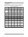
SERVICE MANUAL
RANGER ™ 3000 &
RANGER ™ Count 3000 Scales
Ohaus Corporation, 7 Campus Drive, Suite 310, Parsippany, NJ 07054 (973) 377-9000
SERVICE MANUAL
RANGER ™ 3000 &
RANGER ™ Count 3000 SCALES
The information contained in this manual is believed to be accurate at the time of publication, but Ohaus
Corporation assumes no liability arising from the use or misuse of this material. Reproduction of this
material is strictly prohibited.
Material in this manual is subject to change.
30072402 © Copyright 2013 Ohaus Corporation, all rights reserved.
TM Registered trademark of Ohaus Corporation.
TABLE OF CONTENTS
Page No.
CHAPTER 1 GETTING STARTED
1.1
1.2
1.3
1.4
1.5
Introduction ..............................................................................................................1-1
Service Facilities ......................................................................................................1-1
Tools and Test Equipment Required ........................................................................1-1
Specifications ...........................................................................................................1-2
Scale Operation Ranger Count 3000 .......................................................................1-3
1.5.1 Overview of the Controls ...................................................................................1-3
1.5.2 Power On/Off ....................................................................................................1-4
1.5.3 Menu Setup ......................................................................................................1-5
1.5.4 Menu Navigation ...............................................................................................1-5
1.6 Scale Operation Ranger 3000 ..................................................................................1-6
1.6.1 Overview of the Controls ...................................................................................1-6
1.6.2 Power On/Off ....................................................................................................1-6
1.6.3 Menu Setup ......................................................................................................1-8
1.6.4 Menu Navigation ...............................................................................................1-8
1.7 Legal For Trade .......................................................................................................1-9
1.7.1 Settings.............................................................................................................1-3
1.7.2 Verification ........................................................................................................1-4
1.7.3 Sealing ..............................................................................................................1-5
CHAPTER 2 TROUBLESHOOTING
2.1
2.2
Troubleshooting .......................................................................................................2-1
Diagnostic Guide ......................................................................................................2-1
2.2.1 Diagnosis ..........................................................................................................2-1
2.2.2 Checking Load Cells for Trouble .......................................................................2-2
2.2.3 Testing the Printed Circuit Board (PCB) ............................................................2-4
2.2.4 Diagnostic Guide...............................................................................................2-6
CHAPTER 3 MAINTENANCE PROCEDURES
3.1
Preventive Maintenance ...........................................................................................3-1
3.1.1 Preventive Maintenance Checklist ....................................................................3-1
3.2 Service Strategy.......................................................................................................3-1
3.3 Opening the Scale....................................................................................................3-1
3.2.1 Separating the Top and Bottom Housings .........................................................3-2
3.4 Removing/Replacing the Main Printed Circuit Board (PCB) .....................................3-3
3.5 Removing/Replacing the Load Cell ..........................................................................3-4
3.6 Setting the Overload Stops ......................................................................................3-5
3.7 Removing/Replacing the Rechargeable Battery .......................................................3-7
3.8 Replacing the Function Label ...................................................................................3-7
Ohaus Corporation www.ohaus.com
i
Ranger™ (Count) 3000 Service Manual
TABLE OF CONTENTS
CHAPTER 4 TESTING
4.1. Testing .....................................................................................................................4-1
4.1.1 Test Masses Required ......................................................................................4-1
4.2 Operational Test ......................................................................................................4-1
4.3 Segment Display Test ..............................................................................................4-1
4.4. Performance Tests ...................................................................................................4-2
4.4.1 Precision Test ...................................................................................................4-2
4.4.2 Repeatability Test .............................................................................................4-3
4.4.3 Linearity Test ....................................................................................................4-5
4.4.4 Off-Center Load Test ........................................................................................4-5
4.4.5 Adjusting Off Center Load .................................................................................4-6
CHAPTER 5 DRAWINGS AND PARTS LISTS
5-1
5-2
Ranger 3000 Scales: Housing & Internal Parts ........................................................5-2
Ranger Count 3000 Scales: Housing & Internal Parts ..............................................5-4
Appendix A STANDARD CALIBRATION
A.1 Calibration ............................................................................................................... A-1
A.2 Setup and Calibration.............................................................................................. A-2
Appendix B SERVICE CALIBRATION
B.1 Service Menu Structure ........................................................................................... B-1
B.2 Entering the Service Menu ...................................................................................... B-1
B.3 Capacity Menu ........................................................................................................ B-2
B.4 Graduation Menu .................................................................................................... B-2
B.5 Service Span Calibration ......................................................................................... B-2
B.6 Service Linearity Calibration .................................................................................... B-3
B.7 Ramp Menu ............................................................................................................ B-4
B.8 Expand Menu .......................................................................................................... B-4
B.9 End Menu ............................................................................................................... B-4
LIST OF TABLES
TABLE NO.
1-1
1-2
1-3
1-4
1-5
1-6
1-7
1-8
2-1
2-2
2-3
2-4
3-1
3-2
4-1
4-2
4-3
TITLE
Page No.
Specifications ......................................................................................................1-2
Controls Functions, Ranger Count 3000 ..............................................................1-3
Battery Charge Status Ranger Count 3000 ..........................................................1-4
Ranger Count 3000 Menu Structure ....................................................................1-5
Control Functions, Ranger 3000 ..........................................................................1-6
Battery Charge Status, LCD, Ranger 3000 ..........................................................1-7
Battery Charge Status, LED, Ranger 3000 ..........................................................1-7
Ranger 3000 Menu Structure ...............................................................................1-8
Load Cell Resistance Readings (in Ohms) ..........................................................2-2
Color Code for Load Cell Wiring ..........................................................................2-2
Load Cell Output Readings (in mV with 3.3V Excitation) ......................................2-3
Diagnostic Guide .................................................................................................2-6
Mounting Bolt Torque Settings .............................................................................3-5
Overload Stop Gap Settings ................................................................................3-6
Test Mass Values ................................................................................................4-1
Repeatability Worksheet ......................................................................................4-4
Linearity Test Masses ..........................................................................................4-5
Ranger™ (Count) 3000 Series Service Manual
ii
Ohaus Corporation www.ohaus.com
TABLE OF CONTENTS
5-1
5-2
Ranger 3000 Scales: Housing & Internal Parts ....................................................5-3
Ranger Count 3000 Scales: Housing & Internal Parts..........................................5-5
LIST OF ILLUSTRATIONS
FIGURE NO.
1-1.
1-2.
1-3
2-1
3-1
3-2
3-3
3-4
3-5
3-6
3-7
4-1
5-1
5-2
TITLE
Ranger Count 3000 Front Display with controls ...................................................1-3
Ranger 3000 Front Display with controls .............................................................1-6
LFT Lock Switch and Seal ...................................................................................1-9
Main Printed Curcuit Board ..................................................................................2-3
Screws securing Top Housing .............................................................................3-2
Top and Bottom Bottom .......................................................................................3-2
Main Printed Circuit Board ...................................................................................3-3
Bolts holding Frame to the Load Cell ...................................................................3-4
Overload stops ....................................................................................................3-5
Overload Gap positions .......................................................................................3-6
Rechargeable Battery ..........................................................................................3-7
Scale drawing of Load Cell and Weighing Pan ....................................................4-6
Ranger 3000 Scales: Housing & Internal Parts ....................................................5-2
Ranger Count 3000 Scales: Housing & Internal Parts……………………………...5-4
Ohaus Corporation www.ohaus.com
iii
Ranger™ (Count) 3000 Service Manual
CHAPTER 1 GETTING STARTED
1.1
INTRODUCTION
This service manual contains the information needed to perform routine maintenance and
service on the Ohaus Ranger 3000 and Ranger Count 3000 Series scales. Familiarity with
the scale’s Instruction Manual is assumed. The contents of this manual are contained in five
chapters:
Chapter 1 Getting Started – Contains information on service facilities, tools and test
equipment, specifications, and the mechanical and electronic functions of the scale.
Chapter 2 Troubleshooting – Contains a diagnostic guide and error code table.
Chapter 3 Maintenance Procedures – Contains preventive maintenance procedures and
disassembly, repair and replacement procedures.
Chapter 4 Testing – Contains a list of required test masses, an operational test, segment
display test, performance tests and adjustments.
Chapter 5 Drawings and Parts Lists – Contains exploded views of Ranger 3000 scales
identifying all serviceable components.
Appendix A Standard Calibration – Explains procedures for Standard Calibration,
performed prior to using a scale, and after service.
Appendix B Service Calibration – Describes the Service Menu and sub-menus, which
allow authorized service personnel to perform factory Linearity and Span calibrations (no
pre-set limits), take Ramp readings, and to set the service menu units.
1.2
SERVICE FACILITIES
To service a scale, the service area should meet the following requirements:
Should be temperature controlled and meet scale specifications for temperature
environmental requirements.
Must be free of vibrations such as fork lift trucks close by, large motors, air currents
or drafts from air conditioning/heating ducts, open windows, people walking by, fans,
etc.
Area must be clean and free of excessive dust.
Work surface must be stable and level.
Scale must not be exposed to direct sunlight or radiating heat sources.
Use an approved Electro-Static Device.
1.3
TOOLS AND TEST EQUIPMENT REQUIRED
The service shop should contain the following equipment:
1. Standard hand tools.
2. Digital Voltmeter (DVM).
3. Standard Electronics tool kit.
4. Grounding mat and clip.
5. Strain Gauge Simulator.
Ranger™ (Count) 3000 Series Service Manual
1-1
Ohaus Corporation www.ohaus.com
CHAPTER 1 GETTING STARTED
1.4
SPECIFICATIONS
Complete specifications for the Ohaus Ranger 3000 and Ranger Count 3000 scales are
listed in Table 1-1. When a scale has been serviced, it must meet the specifications listed in
the table. Before servicing the scale, determine what specifications are not met.
TABLE 1-1. SPECIFICATIONS
Model
Capacity
Min (20e)
Standard readability
d=
LFT ON readability
e=10d=
Standard
Resolution
LFT ON
Resolution (nMax)
Linearity 2d
Repeatability 2d
Hysteresis 2d
Off Center Load 2d
Creep (60s, 2d)
Creep (30 min.
0.5e) MPE
Stabilization Time
Combined effect
(Increasing /
Decreasing Load)
Zero Drift vs.
Temp 2d/ C
Span Drift vs. Temp
1d/ C,
Less or equal than
MPE
Operating
Conditions
Storage
Temperature
Pan Size
R31P(E)1502
RC31P1502
R31P(E)3
RC31P3
R31P(E)6
RC31P6
R31P(E)15
RC31P15
R31P(E)30
RC31P30
1.5 kg
3 lb
0.01kg
3 kg
6 lb
0.02kg
6 kg
15 lb
0.04kg
15 kg
30 lb
0.1kg
30 kg
60 lb
0.2kg
0.02lb
0.04lb
0.1lb
0.2lb
0.4lb
0.00005 kg
0.0001 lb
0.0005 kg
0.001 lb
0.0001 kg
0.0002 lb
0.001 kg
0.002 lb
0.0002 kg
0.0005 lb
0.002 kg
0.005 lb
0.0005 kg
0.001 lb
0.005 kg
0.01 lb
0.001 kg
0.002 lb
0.01 kg
0.02 lb
1:30000
1:30000
1:30000
1:30000
1:30000
1:3000
1:3000
1:3000
1:3000
1:3000
0.0001 kg
0.0001 kg
0.0001 kg
0.0001 kg
0.0001 kg
0.0002 kg
0.0002 kg
0.0002 kg
0.0002 kg
0.0002 kg
0.0005 kg
0.0005 kg
0.0005 kg
0.0005 kg
0.0005 kg
0.001 kg
0.001 kg
0.001 kg
0.001 kg
0.001 kg
0.002 kg
0.002 kg
0.002 kg
0.002kg
0.002 kg
0.0002 kg
0.0005 kg
0.001 kg
0.002 kg
0.005 kg
1 sec.
1 sec.
1 sec.
1 sec.
1 sec.
MPE
MPE
MPE
MPE
MPE
0.0001 kg / C
0.0002 kg / C
0.0005 kg / C
0.001 kg / C
0.002 kg / C
16.7ppm / C
16.7ppm / C
16.7ppm / C
16.7ppm / C
16.7ppm / C
-10 C to 40 C
-10 C to 40 C
-10 C to 40 C
-10 C to 40 C
-10 C to 40 C
-40 C to 60 C
-40 C to 60 C
-40 C to 60 C
-40 C to 60 C
-40 C to 60 C
225 x 300 mm
225 x 300 mm
Ohaus Corporation www.ohaus.com
225 x 300 mm
1-2
225 x 300 mm
225 x 300 mm
Ranger™ (Count) 3000 Series Service Manual
CHAPTER 1 GETTING STARTED
1.5
SCALE OPERATION – RANGER COUNT 3000
This section contains information on the basic operation of the Ranger Count 3000 scale.
1.5.1
OVERVIEW OF THE CONTROLS
Figure 1-1. Ranger Count 3000 Front Display with controls.
TABLE 1-2. Control functions Ranger Count 3000
Button
Primary
Function
(Short
1
Press )
Secondary
Function
(Long
2
Press )
Menu
Function
(Short
Press)
Library
Function
(Short
Press)
ON/ZERO
Turn scale
on.
Zero the
display.
PRINT
Send the
displayed value
to the COM
port.
Off
Turn scale
off.
Units
Change the
weighing unit.
Yes
Accept the
current
menu or
setting.
No
Advance to the
next menu or
setting.
Increment the
displayed
value.
No
Advance to the
next library or
setting.
Increment the
displayed
value.
Yes
Accept the
current
setting.
Target
Initiate the
function of the
current
application
mode.
Switch between
Check Weigh,
Check Count
and Off.
Back
Go back to the
previous menu
or setting.
Decrement the
displayed
value.
Back
Go back to the
previous library
or setting.
Decrement the
displayed
value.
Ranger™ (Count) 3000 Series Service Manual
1-3
M+
Accumulate the
weight or pieces.
ID
ID number
input for
library record
edit/recall.
APW
Display/
Store an
APW
Menu
Enter user menu.
View the Audit
Trail event
counters
(extended press)
Exit
Exit the menu.
Abort the
calibration in
progress.
Exit
Exit the library.
Ohaus Corporation www.ohaus.com
CHAPTER 1 GETTING STARTED
TABLE 1-2. Cont.
Button
Primary Function
(Short Press)
0-9
Enter numeric
values on the
display.
Switch between
scale 1 and
scale 2
(only available if
second platform
is connected)
Secondary
Function
(Long Press)
1.5.2
.
Enter dot (.) on
the display.
C
Clear the last
character from
the display.
+/-
Tare
Perform a
tare
operation.
Sample
Display/
Start
new APW
Switch
between
positive and
negative value
Power ON/OFF
To turn the scale on, press and hold the On/Zero Off button for 2 seconds. The scale
performs a display test, momentarily displays the software version, and then enters the
active weighing mode.
To turn the scale off, press and hold the On/Zero Off button until OFF is displayed.
The scale can be used on AC power immediately. Allow the battery to charge for 12
hours before using the scale on battery power. The scale will automatically switch to
battery operation if there is a power failure or the power cord is removed. With AC
power, the scale is constantly charging, so the battery charge indicator will remain lit
until fully charged. The scale can be operated during charging, and the battery is
protected against overcharging.
During battery operation, the battery symbol indicates the battery charge level. The scale
will automatically turn off when the batteries are fully discharged.
For maximum operating time, the battery should be charged at room temperature.
TABLE 1-3 Battery Charge Status Ranger Count 3000
Symbol
Charge Level
0 to 10 % Remaining
11 to 40 % Remaining
41 to 70 % Remaining
71 to 100 % Remaining
Notes:
When battery symbol blinks fast, approximately 30 minutes working time is left.
When [lo.bat] is displayed, the scale will shut off.
Charging the scale must be performed in a dry environment.
CAUTION: Battery is to be replaced only by an authorized Ohaus service
dealer. Risk of explosion can occur if the rechargeable battery is replaced
with the wrong type or if it is not properly connected. Dispose of the lead
acid battery according to local laws and regulations.
Ohaus Corporation www.ohaus.com
1-4
Ranger™ (Count) 3000 Series Service Manual
CHAPTER 1 GETTING STARTED
1.5.3
Menu Setup
Programmable features of the Ranger Count 3000 scales are contained in menus which are
accessed through the Display Panel’s control switches. See the Instruction Manual for a full description of the menus and how to access them.
TABLE 1-4. RANGER COUNT 3000 MENU STRUCTURE
Menu:
C.A.L
S.E.t.U.P
r.E.A.d
U.n.i.t
Span
Reset
Reset
Reset
Lin
D.Scale
Stable
kg
Menu
GEO
Pwr. Un
Filter
g
Items:
End
Zero
AZT
lb
Aut.Opt
Light
oz
A.Tare
A.Off
lb:oz
Bp.Key
End
End
Bp.Opt
Bp.Sig
Accum
End
Menu
Items:
1.5.4
P.r.i.n.t
Reset
Stable
A.Print
Contnt
Layout
Data.Tr
End
C.O.M
Reset
Baud
Parity
Stop
Handsh
Alt.Cm
End
L.O.C.k
L.Cal
L.Setup
L.Read
L.Unit
L.Print
L.COM
End
E.n.d
Menu Navigation
Press and hold Menu until [mMeNU] (Menu) is displayed. When released the first sub-menu
[C.a.l] (Cal) will be shown.
Summary of button navigation functions in menu mode:
-- Yes
Allows entry into the displayed menu.
- Accepts the displayed setting and advances to the next item.
-- No
Skips by the displayed menu.
- Rejects the displayed setting or menu item and advances to the next
available item.
-- Back Moves backwards through the upper and middle level menus.
- Backs out of a list of selectable items to the previous middle level menu.
-- Exit
Exits from menu directly to the active weighing mode.
Ranger™ (Count) 3000 Series Service Manual
1-5
Ohaus Corporation www.ohaus.com
CHAPTER 1 GETTING STARTED
1.6
SCALE OPERATION – RANGER 3000
This section contains information on the basic operation of the Ranger 3000 scale.
1.6.1
OVERVIEW OF THE CONTROLS
Figure 1-2. Ranger 3000 Front Display with controls.
Button
On/Zero
Off
Yes
Print
Units
No
Function
Mode
Back
M+
Menu
Exit
Tare
1.6.2
TABLE 1-5.
Functions
Short Press (when on): Sets display to zero
(when off): Turns scale on
Long Press (when on): Turns the scale off
Short Press (in Menu): Selects/accepts displayed setting
Short Press: Sends current display value to serial port
(auto print OFF).
Long Press: Toggles through active weighing units
Short Press (in Menu): Toggles through available settings
Short Press: Selects function setting
Long Press: Selects active Mode
Short Press (in Menu): returns to previous settings
Short Press: Accumulates the weight or displays the
accumulated information at 0 load.
Long Press: Enters User Menu
Short Press (in Menu): Quickly exit User Menu
Short Press: Enter/clear a tare value. Clears the accumulation
when the accumulation information is displayed.
Power ON/OFF
To turn the scale on, press and hold the On/Zero Off button for 2 seconds. The scale
performs a display test, momentarily displays the software version, and then enters the
active weighing mode.
To turn the scale off, press and hold the On/Zero Off button until OFF is displayed.
Ohaus Corporation www.ohaus.com
1-6
Ranger™ (Count) 3000 Series Service Manual
CHAPTER 1 GETTING STARTED
The scale can be used on AC power immediately. Allow the battery to charge for 12
hours before using the scale on battery power. The Scale will automatically switch to
battery operation if there is a power failure or the power cord is removed. With AC
power, the scale is constantly charging, so the battery charge indicator will remain lit.
The scale can be operated during charging, and the battery is protected against
overcharging.
For maximum operating time, the battery should be charged at room temperature.
LCD models:
During battery operation, the battery symbol indicates the battery charge level
remaining. The indicator will automatically turn off when the batteries are fully charged.
Symbol
TABLE 1-6
Charge level
0 to 10 % Remaining
11 to 40 % Remaining
41 to 70 % Remaining
71 to 100 % Remaining
LED models:
During battery operation, the battery symbol indicates the battery charging status. When
charging, the symbol will blink slowly and when fully charged the symbol will be turned
off.
Symbol
TABLE 1-7
Charge level
Battery in use:
Symbol displayed
Notes:
When battery symbol blinks fast, approximately 30 minutes working time is left.
When [lo.bat] is displayed, the scale will shut off.
Charging the scale must be performed in a dry environment.
CAUTION: Battery is to be replaced only by an authorized Ohaus service
dealer. Risk of explosion can occur if the rechargeable battery is replaced
with the wrong type or if it is not properly connected. Dispose of the lead
acid battery according to local laws and regulations.
Ranger™ (Count) 3000 Series Service Manual
1-7
Ohaus Corporation www.ohaus.com
CHAPTER 1 GETTING STARTED
1.6.3 Menu Setup
Programmable features of the Ranger 3000 scales are contained in menus which are
accessed through the Display Panel’s control switches. See the Instruction Manual for a full description of the menus and how to access them.
TABLE 1-8. RANGER 3000 MENU STRUCTURE
C.A.L
S.E.t.U.P
r.E.A.d
M.O.d.E
Span
Reset
Reset
Reset
Lin
Pwr.Un
Stable
Weigh
Menu
GEO
Zero
Filter
Percnt
Items:
End
A.Tare
AZT
Count
Bp.Sig
Light
Check
Bp.Key
Sleep1
Dynam
Accum
A.Off
End
End
End
Menu:
U.n.i.t
Reset
kg
Menu
g
Items:
lb
oz
lb:oz
End
P.r.i.n.t
Reset
Stable
A.Print
Contnt
Layout
Data.Tr
End
C.O.M
Reset
Baud
Parity
Stop
Handsh
Alt.Cm
End
L.O.C.k
L.Cal
L.Setup
L.Read
L.Mode
L.Unit
L.Print
L.COM
End
E.n.d
Note: 1 only for LED version.
1.6.4
Menu Navigation
Press and hold Menu until [mMeNU] (Menu) is displayed. When released the first sub-menu
[C.a.l] (Calibration) will be shown.
Summary of button navigation functions in menu mode:
-- Yes Allows entry into the displayed menu.
- Accepts the displayed setting and advances to the next item.
-- No
Skips by the displayed menu.
- Rejects the displayed setting or menu item and advances to the next
available item.
-- Back Moves backwards through the upper and middle level menus.
- Backs out of a list of selectable items to the previous middle level menu.
-- Exit Exits from menu directly to the active weighing mode.
Ohaus Corporation www.ohaus.com
1-8
Ranger™ (Count) 3000 Series Service Manual
CHAPTER 1 GETTING STARTED
1.7 LEGAL FOR TRADE
When the scale is used in trade or a legally controlled application it must be set up, verified
and sealed in accordance with local weights and measures regulations. It is the
responsibility of the purchaser to ensure that all pertinent legal requirements are met.
The Menu Lock switch limits changes to the Cal, Setup, Mode and Unit menus. The switch in
type approved models may set some scale settings as required by the approval agency. The
switch may be secured using paper seals, wire seals or plastic ties.
Note: When LEGAL FOR TRADE is set to ON (LFT Switch in locked position), the menu
settings are affected as follows:
Calibration (C.A.L) menu is not accessible
Unit menu, Auto Tare: are locked at their current setting(s)
Filter is locked at current setting
Stable Range setting is locked at 1d
Zero Range setting is locked at 2%.
Auto-Zero Tracking setting is locked at 0.5d
Stable Only is locked On
Auto Print/ Continuous is disabled
1.7.1 Settings
Before verification and sealing, perform the following steps:
1. Verify that the menu settings meet the local weights and measures regulations.
2. Perform a calibration, see instruction manual.
3. Set the switch to Locked. See figure 1-3.
1.7.2 Verification
The local weights and measures official or authorized service agent must perform the
verification procedure.
1.7.3 Sealing
The local weights and measures official or authorized service agent must apply a security
seal to prevent tampering with the settings. Refer to the illustration below for sealing
methods.
Paper Seal
Lock Switch
Unlocked
Locked with Paper Seal
Wire Seal
Locked with Wire Seal
Figure 1-3. Sealing
Ranger™ (Count) 3000 Series Service Manual
1-9
Ohaus Corporation www.ohaus.com
CHAPTER 2 DIAGNOSTIC GUIDE
2.1
TROUBLESHOOTING
This section of the manual contains troubleshooting information. Information is contained to
isolate specific problems using Table 2-4, Diagnostic Guide. Follow all directions step by step.
Make certain that the work area is clean. Handle balance components with care. Use
appropriate Electro-Static Device.
2.2
DIAGNOSTIC GUIDE
Table 2-4 is a Diagnostic Guide designed to help locate the problem area quickly and easily.
The probable causes are listed with the most common cause first. If the first remedy does not fix
the problem, proceed to the next remedy. Before attempting to repair the balance, read all
chapters of this manual to be familiar with the balance components and operation.
2.2.1
Diagnosis
1
Isolate and identify the symptom.
2
Refer to Table 2-4, Diagnostic Guide and locate the symptom.
3
Follow the suggested remedies in the order they appear.
4
Perform the indicated checks, or see the appropriate section of the manual.
5
Repair or replace the defective section of the balance.
NOTE:
If more than one symptom is observed, approach one area at a time,
and remember that the symptoms may be interrelated.
If a problem arises that is not covered in this manual, contact Ohaus Corporation for further
information.
Ranger™ (Count) 3000 Series Service Manual
2-1
Ohaus Corporation www.ohaus.com
CHAPTER 2 DIAGNOSTIC GUIDE
2.2.2
Checking Load Cells for Trouble
1. Perform a Resistance Test, to determine if the Load Cell is severely damaged or a
short circuit to the frame has occurred.
Note: The Load Cell must be completely disconnected from the Printed Circuit
Board and at no load when the resistance readings are taken.
Using an ohm meter, measure and record resistance between each pair of wires
from the Load Cell, as specified in Table 2-1. Compare the measured readings with
the specified values in Table 2-1.
If the resistance readings are in the range specified, skip to the next section. If they
are outside the expected range, open circuit or short-circuit across any two wires, the
Load Cell is defective: replace it. (See Chapter 3.)
TABLE 2-1. LOAD CELL RESISTANCE READINGS (in Ohms)
Model
Ex+ to Ex– S+ to S– Ex+ to S– Ex+ to S+ Ex– to S+ Ex– to S–
All models
404 ± 10
350 ± 4
289 ± 10
289 ± 10
289 ± 10
289 ± 10
2. Perform an Output Voltage Test: Measure the no load, 50% load and full load
output. The reading should meet the Load Cell specifications. The Load Cell output
should be very close to linear over its capacity range.
NOTE: The following steps involve power applied to the scale. Load Cell solder
contacts can be used as measuring points. See Figure 2-1.
The EXE+ and EXE– wires should be connected to the PCB, and the SIG+ and SIG–
wires must be disconnected. Record the colors for each wire connection before
disconnecting. (See Table 2-2 for typical color code for Ranger 2000 and Ranger
Count 2000.)
TABLE 2-2. COLOR CODE FOR LOAD CELL WIRING*
AMI
BLACK
GREEN
WHITE
RED
EXE–
EXE+
SIG+
SIG–
*Color codes may vary.
–
Insert the Platform Support into the Load Cell Frame, place the Platform on top,
and turn on power to the scale.
–
Using a voltmeter, measure and record the excitation voltage supplied to the
PCB: with no load on the Platform, measure the voltage across points 4 and 1 of
Load Cell connection on the PCB (+EXE and –EXE). This voltage must be
approximately 3.1 Volts dc with the Load cell connected. If the voltage is lower,
disconnect the Load Cell cable from the PCB and measure again. If the voltage
is 3.1 Volts dc, the Load Cell is defective and must be replaced. If the voltage
remains low, the PCB is defective and must be replaced.
Ohaus Corporation www.ohaus.com
2-2
Ranger™ (Count) 3000 Series Service Manual
CHAPTER 2 DIAGNOSTIC GUIDE
CAUTION:
IN THE NEXT STEP, DO NOT OVERLOAD THE SCALE BEYOND FULL
CAPACITY RATING.
–
Measure the voltages on +SIG and –SIG wires, disconnected from PCB.
Note: Measurements must be made with these wires disconnected from the
PCB. These measurements represent the output of the Load Cell. Record
measurements at Zero Load, 50% and full scale capacities. See Table 2-3 for
typical readings.
Figure 2-1. Top view of main PCB.
NOTE: Table 2-3 indicates typical readings. Actual values can vary, but should
remain linear throughout the range. If readings are out of tolerance, replace the
Load cell. (See Section 3.6.)
TABLE 2-3. LOAD CELL OUTPUT READINGS (in mV/V with 3.1V Excitation)
Model/Capacity
Zero Load
50% Load
100% Load
0.492666667
0.992666667
1.49266667
R31P(E)3 / 3kg
RC31P3 / 3kg
0.2956
0.8956
1.4956
R31P(E)6 / 6kg
RC31P6 / 6kg
0.1478
0.7478
1.3478
R31P(E)15 / 15kg
RC31P15 / 15kg
0.0739
0.8239
1.5739
R31P(E)30 / 30 kg
RC31P30 / 30 kg
0.03695
0.78695
1.53695
R31P(E)1502 / 1.5kg
RC31P1502 / 1.5kg
Ranger™ (Count) 3000 Series Service Manual
2-3
Ohaus Corporation www.ohaus.com
CHAPTER 2 DIAGNOSTIC GUIDE
2.2.3
Testing the Printed Circuit Board (PCB)
The PCB can be tested by measuring voltages and by using a simulator. The simulator replaces
the Load Cell during testing and is a useful tool for diagnosing problems.
PCB Voltage Measurements
Note: Prior to the voltage measurements, the battery should be fully charged and tested.
1. Disconnect power from the scale, and remove the Top housing. (See Section 3.3.1.)
CAUTION: Disconnect the power from the scale before opening the housing.
2. Connect the AC Adapter to the scale and turn the scale on.
3. Using a DVM, measure the excitation voltage (EXE+ and EXE– in Figure 2-1.)
The reading should be 3.1 volts dc. This is the excitation voltage for the Load Cell
and is regulated. If the voltage is lower, replace the PCB. (See Section 3.4.)
Then perform Operational Tests. (See Chapter 4.)
4. Measure incoming power from the transformer connector shown in Figure 2-1. The
voltage should read 0 volts with power off and above 12 Volts dc with power on.
5. Perform simulator testing.
Simulator Testing
To perform these tests, the use of a Simulator is required. The function of a Simulator is to
simulate the output of a full bridge Load Cell, allowing the scale to be separated from the Load
Cell for the purposes of troubleshooting and calibration. The Load Cell used in the scale is rated
at 2mV/V output with a 3.1 Volt excitation voltage applied.
Ohaus Corporation www.ohaus.com
2-4
Ranger™ (Count) 3000 Series Service Manual
CHAPTER 2 DIAGNOSTIC GUIDE
General Load Test
This test checks the Main PC Board circuitry by simulating accurate Load Cell voltages at zero
load, 50% and 100% load capacities.
Disconnect power from the scale, and remove the Top housing. (See Section 3.3.1.) Leave the
Mechanical Switch connected to the scale. Disconnect the battery.
1. Disconnect the Load Cell cable from the main PC Board.
2. With the Simulator set to zero, solder its cable leads to their counterparts on the
PCB, using the Load Cell Cable solder points on the PCB. (See Figure 2-1.).
3. Connect a known good AC Adapter to the scale and connect to a power source.
4. Turn on the scale. An under load error may appear. This is normal.
5. Set the scale to indicate weight in kilograms (kg) and set the calibration value to
maximum span value.
6. Adjust the Simulator to simulate 0% load, 50% load and 100% load for the capacity
that the scale is rated for. (See Table 2.3 for values to use.) If the resulting readings
are unstable, the Main PC Board is defective.
7. Use the Simulator to calibrate the scale in the next procedure to verify if the Main PC
Board is good or bad.
Calibration Test
This test calibrates the scale using the simulator and can verify that the Main PC Board is
functioning properly or improperly.
1. With the scale on, enter the scale menu and perform a span calibration.
(See Appendix A.)
2. Follow the scale prompts. When the scale indicates a given weight to be placed
on the scale, set the simulator to an equivalent value based on Table 2-3.
3. Upon completion of calibration, the PCB can be further checked using the Simulator
to simulate various weight values. If simulator settings and weight readings on the
scale agree, the PCB is functional. If the scale readings vary, or do not agree with
readings in Table 2-3, the Main PC Board is defective and should be replaced.
(See Chapter 3.)
Ranger™ (Count) 3000 Series Service Manual
2-5
Ohaus Corporation www.ohaus.com
CHAPTER 2 DIAGNOSTIC GUIDE
2.2.4
Diagnostic Guide
TABLE 2-4. DIAGNOSTIC GUIDE
Symptom
Cannot turn on
Cannot calibrate
Cannot access mode
Cannot access unit
Possible Cause
No power to scale
Improper calibration
Unstable environment
LFT locked
Mode not enabled
Unit not enabled
Battery icon flashing
Low Battery error
Err 8.1
Power On Error
Err 8.2
Power On Error
Err 8.3
Over Range Error
Weight reading exceeds Overload limit
Err
Err
Err
Err
Under Range Error
Tare out of range
Display overflow
Calibration data error
Weight reading below Underload limit
Adjust tare value to be within range
Weight exceeds 6 digits
Calibration data not present
-------
Busy
Displayed during tare setting, zero
setting, printing
--NO--
Action not allowed
Function not executed
CAL E
Calibration error
Calibration value outside allowed limits
Unstable environment
Move the scale to suitable location
Incorrect calibration weight Use correct calibration weight
Lo.ref
Low reference weight
warning
ref.err
Unacceptable reference
weight
Battery fails to charge
fully
Battery is defective
Poor accuracy
8.4
8.5
8.6
9.5
Ohaus Corporation www.ohaus.com
2-6
Remedy
Verify connections and voltage
Perform calibration
Move scale to suitable location
See chapter 5 for information.
Enter menu and enable mode
Enter menu and enable unit
Connect scale to AC power and charge
the battery
Weight reading exceeds Power On Zero
limit
Weight reading below Power On Zero
limit
Increase reference weight
Reference weight too small. Weight on
the pan is too small to define a valid
reference weight. Increase reference
weight.
Have battery replaced by Ohaus
authorized service dealer.
Ranger™ (Count) 3000 Series Service Manual
CHAPTER 3 MAINTENANCE PROCEDURES
3.1
PREVENTIVE MAINTENANCE
Ohaus scales are precision instruments and should be carefully handled, stored in a clean, dry,
dust-free area, and cleaned periodically. Follow these precautionary steps:
–
When a scale has had chemicals or liquids spilled on it, all exterior surfaces should be
cleaned as soon as possible with warm water on a damp cloth.
–
Do not leave a mass on the scale when the scale is not in use.
–
Allow time for the scale to stabilize after moving it from an area which is at a different
temperature than the area where it is to be operated. Allow one hour for each 5°F
(2.7°C) temperature change before using the scale. After temperature stabilization,
allow another 20 minutes after turning the scale on, for the scale electronics to stabilize.
3.1.1
Preventive Maintenance Checklist
The scale should be inspected and checked regularly, as follows:
1. Remove the Pan and Sub Pan to inspect and clean the area beneath the Pan.
2. Clean the outside of the scale using a damp cloth with warm water.
CAUTION
DO NOT USE CHEMICAL CLEANERS OR SOLVENTS OF ANY TYPE.
SOME CLEANERS ARE ABRASIVE AND MAY AFFECT THE SCALE’S FINISH.
3. Check the Power Cord for broken or damaged insulation.
4. If using the rechargeable battery and the scale malfunctions, first recharge the
battery to see if this resolves the problem.
5. Make a visual inspection for faulty connectors, wiring, and loose hardware.
3.2
SERVICE STRATEGY
All parts of the Ranger 3000 and Ranger Count 3000 are designed to be replaced rather than
repaired. This includes the Main Printed Circuit Board (PCB) and Switches PCB, the Load Cell,
and the cables. For an illustrated list of replaceable parts, see Chapter 5.
3.3
OPENING THE SCALE
Use these procedures in order to replace the Load Cell, any of the Printed Circuit Boards and/or
LCD Displays.
Ranger™ (Count) 3000 Series Service Manual
3-1
Ohaus Corporation www.ohaus.com
CHAPTER 3 MAINTENANCE PROCEDURES
3.3.1
Separating the Top and Bottom Housings
Common hand tools are sufficient to disassemble the Ranger 3000 and Ranger Count 3000
scales. Turn the scale off and unplug the power cord before you begin.
1. Lift off the Weighing Pan.
2. Turn the scale over. Remove the eight screws holding the Housing in place.
(See Figure 3-1.)
3. Move the top housing a little bit
backward and then raise and remove
the top housing.
4. Separate Top Housing from Bottom
Housing. Avoid straining the cables
that connect the Main PCB to the
parts in the Bottom Housing. (Lay
the two housings close to each
other, so cable is not strained.)
Figure 3-1. Ranger 3000 Bottom.
Figure 3-1. Screws (marked with white
circles) that secure the housing.
Display
PCB
Main
PCB
Load
Cell
Frame
Load Cell Cable
leads.
Figure 3-2. Top and Bottom Housings
Ohaus Corporation www.ohaus.com
3-2
Ranger™ (Count) 3000 Series Service Manual
CHAPTER 3 MAINTENANCE PROCEDURES
3.4
Removing/Replacing the Main PCB and Display PCB
If the PCBs are suspected of being faulty, they should be replaced, as follows:
1. Disconnect the Cable connecting the Main PCB to the scale’s power system. (See Figure 3-2.)
2. Remove the four screws that secure the PCB to the bottom housing.
3. If either the Main PCB or the Load Cell is to be replaced, note the order of the wire
colors and then disconnect the Load Cell Cable from the Main PCB. (See Figure 32.)
4. Position the replacement PCB as in Figure 3-2, insert and tighten the screws.
5. Re-connect the Load Cell Cables to the PCB, in the same position as originally
installed.
6. Re-connect the Cable connecting the Main PCB to the scale’s power system. (See Figure 3-2.)
7. Insert and tighten the screws that secure the PCB to the bottom housing.
Figure 3-3. Main Printed Circuit Board.
Ranger™ (Count) 3000 Series Service Manual
3-3
Ohaus Corporation www.ohaus.com
CHAPTER 3 MAINTENANCE PROCEDURES
3.5
Removing/Replacing the Load Cell
A Load Cell that is even slightly bent or corroded should be replaced. The Load Cell may also
need to be replaced because of instability, or because the scale does not calibrate or repeat.
Note: The Load Cell is sold separately. (See Chapter 5.)
1. Unplug the cable leads connecting the Load Cell to the PCB. (See Figure 3-2.)
2. Turn the scale over and remove the bolts and washers that hold the Load Cell
assembly (frame and load cell) to the Bottom Housing.
Remove the bolts and their washer
pairs that hold the Load Cell
Frame to the Load Cell. Use a
high-leverage Allen wrench.
3. Lift the Load Cell away from
the frame.
Figure 3-4. Remove the bolts holding Frame to the
Load Cell.
4. When installing the replacement Load Cell, first secure the bottom frame to the load
cell with the screws and then secure the top frame to the load cell. Adjust the
down/up stop gaps (see table 3-2). Install the load cell assembly to the bottom
housing. Insert the bolts and their washers, and tighten the bolts. (See Table 3-1 for
torque settings.)
5. Connect the Load Cell cables to the PCB. (See Figure 3-2.)
Ohaus Corporation www.ohaus.com
3-4
Ranger™ (Count) 3000 Series Service Manual
CHAPTER 3 MAINTENANCE PROCEDURES
TABLE 3-1. MOUNTING BOLT TORQUE SETTINGS
MODEL
TORQUE SETTING
R31P(E)1502
RC31P1502
6N to 8N
R31P(E)3
RC31P3
6N to 8N
R31P(E)6
RC31P6
6N to 8N
R31P(E)15
RC31P15
6N to 8N
R31P(E)30
RC31P30
6N to 8N
6. Set Overload Stops as shown in Section 3.6.
3.6
Setting the Overload Stops
The Overload Stop gaps must be checked and reset if the Load Cell is replaced. This
procedure requires test masses equal to the scale’s capacity. (See Table 3-2.)
There are four Overload Stop Bolts. (See Figure 3-5.)
Adjust the Overload Stops, per Table 3-2:
1. Adjust the Overload Stop Bolt so that
the gap between the Load Cell Frame
and the Overload Stop Nut is equal to
the specification in Table 3-2. (The
gap can be tested by applying 100%
load, one corner at a time, at each
corner stop. If the gap is right, the
Load Cell Frame will just touch the
Overload
Overload Stop Nut.)
Stops
Note: Be careful not to overload the
Load Cell, which would damage it.
Figure 3-5. Overload Stops.
2. Repeat this for all four corners.
3. Test the scale to see if full capacity
can be achieved.
Ranger™ (Count) 3000 Series Service Manual
3-5
Ohaus Corporation www.ohaus.com
CHAPTER 3 MAINTENANCE PROCEDURES
TABLE 3-2. Ranger 3000/Ranger Count 3000 OVERLOAD STOP GAP SETTINGS
Model
Max. Capacity
Overload Stop Gap
R3000 / RC 3000 Scale
Load Cell
A/B mm
C/D mm
1.5kg
3kg
0.6
0.5
R31P(E)3
RC31P3
3kg
5kg
0.8
0.7
R31P(E)6
RC31P6
6kg
10kg
1.5
1.1
R31P(E)15
RC31P15
15kg
20kg
2.4
1.7
R31P(E)30
RC31P30
30kg
40kg
2.4
1.7
R31P(E)1502
RC31P1502
A
D
Load Cell
B
C
Figure 3-6. Gap position of corners A, B, C, D. (A & B represent the front of the scale.)
Ohaus Corporation www.ohaus.com
3-6
Ranger™ (Count) 3000 Series Service Manual
CHAPTER 3 MAINTENANCE PROCEDURES
3.7
Removing/Replacing the Rechargeable Battery
The Ranger 3000/Ranger Count 3000 has a
rechargeable battery.
If it fails to recharge, replace it as follows:
1. Lift the battery’s front end enough to access the quick-connect tabs holding
the wire leads.
Note: Be careful not to short-circuit the
battery leads.
2. Pull the quick-connect tabs free of
the battery posts, and lift out the
battery.
Figure 3-7. Rechargeable battery.
3. Position the replacement battery in the compartment on an angle sufficient to access
the battery posts.
4. Insert the quick-connect tabs on their respective posts, and place the battery fully in
the battery compartment
3.8
Replacing the Function Label
The Function Label may need to be replaced. (See Chapter 5 for parts information.)
Use a broad knife to remove the label. Clean the glue residue from the Housing surface.
Then carefully place the new label where the old one was.
Ranger™ (Count) 3000 Series Service Manual
3-7
Ohaus Corporation www.ohaus.com
CHAPTER 4 TESTING
4.1
TESTING
Before and after servicing a Ranger 3000/Ranger Count 3000 scale, an operational test and
various performance tests should be made to confirm that the scale meets specifications. Turn
the scale on and allow it to warm up for at least one hour before performing these tests.
NOTE:
Make sure the test area is free from drafts and that the scale rests on a level and
vibration-free surface.
4.1.1
TEST MASSES REQUIRED
The masses required to test the Ohaus Ranger 3000/Ranger Count 3000 scales must meet the
requirements of ASTM Class 4 or OIML F2 Tolerance. The mass values are listed in Table 4-1.
TABLE 4-1. TEST MASS VALUES
4.2
Model
Weight (g)
R31P(E)1502
RC31P1502
1kg,500g,200g
R31P(E)3
RC31P3
1kg,500g
R31P(E)6
RC31P6
2kg,1kg,500g
R31P(E)15
RC31P15
10kg,5kg,2kg
R31P(E)30
RC31P30
10kg,5kg
Operational Test
1. Connect a functioning Power cord to the back of the scale.
2. Plug the Power Cord into a suitable power source, or power the scale on using
battery power. (Assure that the battery is charged beforehand.)
4.3
Segment Display Test
Turn the scale on, and ensure that all segments are enabled and displayed briefly and
followed by a software revision number.
Ranger™ (Count) 3000 Series Service Manual 4-1
Ohaus Corporation www.ohaus.com
CHAPTER 4 TESTING
4.4
Performance Tests
Accurate performance of the Ranger 3000/Ranger Count 3000 scale is determined by a series
of four performance tests. The displayed readings are compared with the tolerances listed for
each test in Table
1-2. Tolerance values are expressed in counts. A one-count difference is shown in the last digit
on the scale display.
NOTE:
The following performance tests are used to evaluate scale operation before and
after repairs. The scale must meet the requirements specified in each test as well
as the other specifications listed in Table 1-1. Before proceeding with the
following tests, the scale should be calibrated. (See Appendix A and B.)
4.4.1
Precision Test
The Precision Test measures the Standard Deviation of a set of similar weight readings, which
should match the specification for each model, listed in Table 1-1.
1. Power on the balance. The reading on the display should be 0g.
2. Select a mass weighing near the maximum capacity of the balance, and place it on
the center of the Pan. Observe and record the reading.
3. Remove the mass. The reading should return to 0g ±2 count.
4. Repeat this test three times. The reading should be within ±2 count of the reading
recorded. If so, the balance passes the Precision Test.
5. If the deviation for any set of readings (using the same mass placed on the center of
the Pan) is greater than ±2 d, the balance does not meet the precision specification.
Inspect and correct the following areas:
–
Check for mechanical obstructions. Any foreign object touching any part of the
moving assemblies will cause a balance to fail the Precision Test. Inspect and
correct as necessary.
–
If the scale does not meet specifications, move it to a suitable location, ensure
that it is level, and try again. If it still does not meet specifications, perform a
service calibration, and try again. (See Appendix B for Service Calibration.)
Ohaus Corporation www.ohaus.com
4-2
Ranger™ (Count) 3000 Series Service Manual
CHAPTER 4 TESTING
4.4.2
Repeatability Test
Repeatability is the Standard Deviation of a set of similar weight readings.
Requirements:
– To perform this test a single mass must be used for all readings.
–
The test mass should be approximately ½ of the capacity of the instrument.
–
Wear gloves when handling the mass.
Before starting a repeatability test, set up the instrument as follows:
Set Up:
Follow the steps in Appendix A, Section A-2, Setup and Calibration.
Record Settings:
Zero Tracking Setting =
____________
Displayed Units =
____________
Mass Used =
____________
TEST PROCEDURE:
1. Zero the instrument, if it does not read zero.
2. Using a test mass approximately half the capacity of the instrument, place the mass on
the center of platform. Record the reading on the worksheet provided.
3. Remove the mass from the platform.
4. Repeat this test starting at Step 1 until you record a total of ten readings
Fill in the worksheet (Table 4-2) with the ten (10) readings.
Ranger™ (Count) 3000 Series Service Manual 4-3
Ohaus Corporation www.ohaus.com
CHAPTER 4 TESTING
TABLE 4-2. REPEATABILITY WORKSHEET
n
Reading
Delta = Reading – Mean
Delta x Delta
1
2
3
4
5
6
7
8
9
10
n = number of Reading
Mean = Sum of readings / 10
Delta = Reading – Mean
Standard Deviation = Square Root of (sum of (Delta x Delta) / 9)
5. Add the ten readings and divide the total by 10 to find the Mean (average).
6. Mean = (Reading 1 + Reading 2 + Reading 3 + Reading 4 + Reading 5
7. + Reading 6 + Reading 7+ Reading 8 + Reading 9 + Reading 10) / 10
Mean =________
6. Calculate the Delta for each reading and record in the work sheet.
Delta = Reading – Mean
7. Calculate the Delta x Delta for each reading and record in worksheet.
8. Add the ten Delta x Delta values and divide by 9
9. Calculate the Standard Deviation by applying the square root of the result from step 8.
Standard Deviation =___________
Note: If the balance does not meet specifications, move it to a suitable location, ensure
that it is level, and try again.
Ohaus Corporation www.ohaus.com
4-4
Ranger™ (Count) 3000 Series Service Manual
CHAPTER 4 TESTING
4.4.3
Linearity Test
This test is used to determine the linearity of the unit throughout its operating range.
The masses used to perform this test can be utility masses
NOTE:
The scale must pass the Precision and Repeatability Tests, and be calibrated before
the Linearity Test may be performed.
TABLE 4-3. LINEARITY TEST MASSES
1500 x 0.05 g
3000 x 0.1g
6000 x 0.2g
15000 x 0.5g
30000 x 1g
Reference Wt.
500g
500g
1kg
2kg
5kg
Load 1
200g
1000g
2kg
5kg
10kg
Load 2
500g
1000g
1kg
5kg
10kg
Load 3
200g
500g
2kg
2kg
5kg
Capacity (g)
NOTE:
All masses are nominal values. Use the same reference mass throughout the procedure.
1. Place the test mass on the Scale, record the weight and remove.
2. Place Load 1 on the Scale and press ON/ Zero - Off.
3. Place the test mass on the Scale, record the weight and remove.
4. Place Load 2 on the Scale and press ON/ Zero - Off.
5. Place the test mass on the Scale, record the weight and remove.
6. Place Load 3 on the Scale and press ON/ Zero - Off.
7. Place the test mass on the Scale and record the weight.
8. The difference in the weights of the test mass should be within ±2 d, as specified in
the Tables 1-1 and 1-2. If not, calibrate (see Appendix A.1) and repeat the test.
9. If the Scale remains out of tolerance, the Load Cell may need to be replaced.
4.4.4
Off-Center Load Test
The Off-Center Load Test is used to determine whether displayed weight values are affected by
moving the sample to different areas of the Pan.
1. Place half of the scale’s capacity in the center of the Pan.
2. Note the reading.
3. Move the mass halfway (between the center and the edge) to the front of the Pan.
Note any differences in the displayed weight reading.
4. Repeat the test for the back, left, and right position of the Pan.
Ranger™ (Count) 3000 Series Service Manual 4-5
Ohaus Corporation www.ohaus.com
CHAPTER 4 TESTING
5. Maximum allowable change in displayed weight readings for each of the four
positions can be found in Tables 1-1 (Specifications, page 1-2).
If this maximum is exceeded, follow procedures in Section 4.4.5, Adjusting Off
Center Load.
4.4.5
Adjusting Off Center Load
If the Off Center Load (OCL) is excessive, perform adjustment as follows:
C
D
B
2
3
1
4
Top view of Load Cell
Pan
Fixed end
Side view of Load Cell
A
Weighing Pan’s center,
with points A – D indicated
2
3
1
4
Figure 4-1. Scale drawing of Ranger 3000/Ranger Count 3000 Load Cell and Weighing Pan.
1. Place the test weight in the center of the Weighing Pan.
2. Tare the balance.
3. Move the weight to point A and record the reading.
4. Move the weight to point B and record the reading.
5. Move the weight to point C and record the reading.
6. Move the weight to point D and record the reading.
7. If the reading at point A is negative, file at points 1 and 4 AT AN ANGLE.
8. If the reading at point B is negative, file at points 1 and 2 STRAIGHT ACROSS.
9. If the reading at point C is negative, file at points 2 and 3 AT AN ANGLE.
10. If the reading at point D is negative, file at points 3 and 4 STRAIGHT ACROSS.
Note: It is not recommended that you try to adjust more than –5 counts if the beam has
been filed already. If the beam has not been filed previously, you can adjust –10 counts.
Remember, when filing you are weakening the beam. File a little at a time.
Ohaus Corporation www.ohaus.com
4-6
Ranger™ (Count) 3000 Series Service Manual
CHAPTER 5 PARTS LISTS & DIAGRAMS
This section of the manual contains exploded views of the Ranger 3000/Ranger Count 3000
scales. The exploded view drawings are designed to identify the parts which can be serviced on
the scale in the field.
NOTE:
In all cases where a part is replaced, the scale must be thoroughly checked after
the replacement is made. The scale MUST meet the parameters of all applicable
specifications in this manual.
If further technical information is needed, please contact your local Ohaus distributor, or:
www.ohaus.com
Ohaus Corporation,
7 Campus Drive
Suite 310
Parsippany, NJ 07054 USA
Tel: 973-377-9000
Fax: 973-593-0359
In the United States call toll free, 800-526-0659 between 8:00 a.m. and 6:00 p.m. EST.
Ranger™ (Count) 3000 Series Service Manual 5-1
Ohaus Corporation www.ohaus.com
CHAPTER 5 PARTS LISTS & DIAGRAMS
5.1
Ranger 3000 SCALES: PARTS
Figure 5-1. Ranger 3000 Scales: Parts.
Ohaus Corporation www.ohaus.com
5-2
Ranger™ (Count) 3000 Series Service Manual
CHAPTER 5 PARTS LISTS & DIAGRAMS
TABLE 5-1. Ranger 3000 SCALES: PARTS
Drawing Item
1
2
3
4
5
6
7
8
9
10
11
12
13
14
15
NA
NA
NA
NA
NA
NA
NA
NA
NA
NA
Part Number
30037417
30037393
30025994
30060924
30037465
30037430
30037432
30037434
30037401
30037402
30037403
30037404
30037405
30037435
30037420
30037398
30037421
30037422
30037392
30037428
30037423
30037419
30037383
30037384
30037455
30060917
72200232
72200229
72200228
72200231
72200230
30031898
Description
Pan,Plastic,R31,RC31,V71
Housing,Top,R31
Function Label,R31, English
Function Label, R31PE, Japanese
Function Label, R31, KR
PCBA,Display,LCD,R31,R21,V71
PCBA,Display,LED,R31,R21
Spider,Upper, R31,R21,RC31,RC21,V71
LoadCell AMI C3 3kg, R31P1502, R31PE1502JP
LoadCell AMI C3 5kg,R31P3, R31PE3JP
LoadCell AMI C3 11kg,R31P6, R31PE6JP
LoadCell AMI C3 22kg ,R31P15, R31PE15JP
LoadCell AMI C3 40kg,R31P30, R31PE30JP
Spider,Down, R31,R21,RC31,RC21,V71
Hardware Kit,R31,R21,RC31,RC21,V71
Housing,Bottom, R31
Feet,R31,R21,RC31,RC21,V71
Cover,Option, R31,R21,RC31,RC21,V71
Switch Power, R31,RC31,V71
PCBA,Main,R31,RC31,V71
Battery,Lead Acid,R31,R21,RC31,RC21,V71
Harness,R31,R21,RC31,RC21,V71
Packaging Box carton,R31,R21,RC31,RC21,V71
Packaging Box,complete,R31,R21,RC31,RC21,V71
Manual, Instr.,JP,R31
Manual, Instr.,KR,R31
Line Cord , US
Line Cord, EU
Line Cord, AU
Line Cord, GB
Line Cord, JP
Manual,CD, EN ES FR DE IT, V71
Note: For parts numbers, see your local Ohaus distributor, or visit www.ohaus.com.
Ranger™ (Count) 3000 Series Service Manual 5-3
Ohaus Corporation www.ohaus.com
CHAPTER 5 PARTS LISTS & DIAGRAMS
5.2
RANGER COUNT 3000 SCALES: PARTS
Figure 5-2. Ranger Count 3000 Scales: Parts.
Ohaus Corporation www.ohaus.com
5-4
Ranger™ (Count) 3000 Series Service Manual
CHAPTER 5 PARTS LISTS & DIAGRAMS
TABLE 5-2. RANGER COUNT 3000 SCALES: PARTS
Drawing Item
1
2
3
4
5
6
7
8
9
10
11
12
13
14
15
NA
NA
NA
NA
NA
NA
NA
NA
NA
NA
Part Number
30037417
30037394
30025996
30060925
30037464
30037431
30037434
30037401
30037402
30037403
30037404
30037405
30037435
30037420
30037398
30037421
30037422
30037392
30037428
30037423
30037419
30037383
30037384
30037456
30060918
72200232
72200229
72200228
72200231
72200230
30031898
Description
Pan,Plastic,R31,RC31,V71
Housing,Top,RC31
Function Label,RC31, English
Function Label,RC31, Japanese
Function Label,RC31, KR
PCBA,Display,LCD,RC31,RC21
Spider,Upper, R31,R21,RC31,RC21,V71
LoadCell AMI C3 3kg,RC31P1502
LoadCell AMI C3 5kg,RC31P3
LoadCell AMI C3 11kg,RC31P6
LoadCell AMI C3 22kg ,RC31P15
LoadCell AMI C3 40kg,,RC31P30
Spider,Down, R31,R21,RC31,RC21,V71
Hardware Kit,R31,R21,RC31,RC21,V71
Housing,Bottom, R31
Feet,R31,R21,RC31,RC21,V71
Cover,Option, R31,R21,RC31,RC21,V71
Switch Power, R31,RC31,V71
PCBA,Main,R31,RC31,V71
Battery,Lead Acid,R31,R21,RC31,RC21,V71
Harness,R31,R21,RC31,RC21,V71
Packaging Box carton,R31,R21,RC31,RC21,V71
Packaging Box,complete,R31,R21,RC31,RC21,V71
Manual, Instr.,JP,RC31
Manual, Instr.,KR,RC31
Line Cord , US
Line Cord, EU
Line Cord, AU
Line Cord, GB
Line Cord, JP
Manual,CD, EN ES FR DE IT, V71
Note: For parts numbers, see your local Ohaus distributor, or visit www.ohaus.com.
Ranger™ (Count) 3000 Series Service Manual 5-5
Ohaus Corporation www.ohaus.com
APPENDIX A STANDARD CALIBRATION
APPENDIX A. STANDARD CALIBRATION & SETUP
A.1 CALIBRATION
Standard calibration should be performed prior to using a scale, and after service.
NOTE:
Be careful not to touch the scale or the table while calibration is in progress,
as it will cause the process to fail.
Preliminary Steps:
1. Be sure the scale is level and stable during the entire calibration process.
2. Allow the scale to warm up for approximately five minutes after stabilizing to room
temperature.
3. To abort calibration, press Exit key or turn the scale off anytime during the calibration
process.
4. Before performing the calibration, be sure to have the appropriate calibration weights as
listed in table A-1.
5. Ensure that the LFT switch/calibration lock is set to unlocked position.
6. Or adjust the GEO setting according to your location (see instruction manual).
Table A-1.
Suggested Span Calibration Mass (sold separately)
1
1
Max
Max
Mass
Mass
1500g
1.5kg / 3lb
15000g
15kg / 30lb
3000g
3kg / 6lb
30000g
30kg / 60lb
6000g
6kg / 15lb
Ranger™ 3000 Series Service Manual
A-1
Ohaus Corporation www.ohaus.com
APPENDIX A STANDARD CALIBRATION
A.2
SETUP AND CALIBRATION
Note: Be sure units are set to kg before starting calibration.
1. Turn on the scale. Press and hold Menu until [mMeNU] (Menu) is
displayed. When the button is released, the display will show [C.A.L].
2. Press Yes to accept. [SpaN] will then be shown. Press Yes to begin the
span calibration. [ 0 kg] will be displayed.
mMeNU
C.A.L
SpaN
0
3. Press Yes to accept. [--C--] will be displayed while zero reading is
stored. Next, the display shows the calibration weight value (e.g. 3).
--C—
3
4. Place the specified calibration mass on the pan. Press Yes to accept
the weight or No to select an alternate weight. [--C--] will be
displayed while the reading is stored.
--C--
5. The display will show [done] if the calibration was successful. The scale
returns to the previous application mode and is ready for use.
Ohaus Corporation www.ohaus.com
A-2
done
Ranger™ 3000 Series Service Manual
APPENDIX B SERVICE CALIBRATION
APPENDIX B. SERVICE CALIBRATION
This section describes the Service Menu and sub-menus, which allow authorized service
personnel to perform factory Linearity and Span calibrations (no pre-set limits).
Note:
Be careful not to touch the scale or the surface it rests on while calibration is in
progress, as it will cause the process to fail.
B.1 Service Menu Structure
Service
Cap
Grad
Span
Lin
Ramp
Expand
End
B.2 Entering the Service Menu
Turn the scale off.
Ranger Count 3000
Press the On/Zero then hold the Target and M+ keys simultaneously
for 6 seconds until S.E.r.V.C.e appears in the weight window.
S.E.r.V.C.e
Ranger 3000
Press the On/Zero then hold the Function and M+ keys
simultaneously for 6 seconds until S.E.r.V.C.e is displayed.
Ranger™ 3000 Series Service Manual
B-1
S.E.r.V.C.e
Ohaus Corporation www.ohaus.com
APPENDIX B SERVICE CALIBRATION
B.3 Capacity Menu
When CAP appears, press YES to accept the Capacity menu item,
or press NO to advance to the menu item.
CAP
The current Capacity Setting is displayed, blinking.
(Outlined characters represent a flashing display.)
Note: The default setting is 3
Press YES to accept the setting and move to the Service Grad menu
item.
Press NO to enter another value using the numeric keypad and then
press YES to store the new value.
B.4 Graduation Menu
When GrAd appears, press YES to accept the Graduation menu or No
to advance to the Service Span Calibration menu.
Grad
Set the graduation of the scale.
0.00005,…,0.02
B.5 Service Span Calibration
SPAN
When SPAN appears, press YES to accept the Service Span
Calibration menu or No to advance to the Service Linearity
Calibration menu.
0 flashes. With no weight on the pan, press Yes to establish the
zero point. (Outlined characters represent a flashing display.)
--C--—
- - C - - flashes while the zero point is established.
Service Span Calibration point flashes.
(The example shows the value for a Scale Capacity of 3 kg.)
Place the specified calibration weight on the pan and press Yes.
- - C - - flashes while the span point is established.
If span calibration was successful, the actual weight reading
appears for three seconds, followed by the Service Linearity
Calibration menu item.
(The example shows a 3 kg span weight on the pan.)
Ohaus Corporation www.ohaus.com
B-2
--C--—
3.000
Ranger™ 3000 Series Service Manual
APPENDIX B SERVICE CALIBRATION
B.6 Service Linearity Calibration
This calibration method uses three points. The full-calibration point is established with a weight
on the scale. The mid-calibration point is established with a weight equal to half of the full
calibration weight on the scale. The zero calibration point is established with no weight on the
scale. The mid-calibration points cannot be altered by the user during the calibration procedure.
When LIN appears, press YES to accept the Service Linearity Calibration
menu, or No to advance to the Ramp menu item.
LIN
0 flashes. The kg LED is lit to indicate the calibration unit.
With no weight on the pan, press Yes to establish the zero point.
(Outlined characters represent a flashing display.)
--C--
- - C - - flashes while the zero point is established.
The mid calibration point value flashes. The kg LED is lit to indicate the
calibration unit. (The example shows the mid calibration point value for a
Scale Capacity of 3 kg.)
Place the specified calibration weight on the pan and press Yes.
--C--
- - C - - flashes while the mid point is established.
The full calibration point value flashes. The kg LED is lit to indicate the
calibration unit. (The example shows the full calibration point value for a
Scale Capacity of 3 kg.)
Place the specified calibration weight on the pan and press Yes.
- - C - - flashes while the full point is established.
If linearity calibration was successful, the scale will exit the service menu
and enter weighing mode.
(The example shows a 3 kg span weight on the pan.)
If linearity calibration was successful, S.End appears.
Press YES to exit the Service menu and return to the weighing mode,
or NO to return to the first Service menu item.
--C-3.000
End
NOTE: If calibration fails, ensure that the test area is free from drafts and the surface the scale
rests on is level and free of vibrations. Then try to calibrate again. If it continues to fail, there
may be an internal problem. To resolve internal problems, follow procedures in Chapter 3.
Ranger™ 3000 Series Service Manual
B-3
Ohaus Corporation www.ohaus.com
APPENDIX B SERVICE CALIBRATION
B.7 Ramp Menu
When ramMp appears, press YES to accept the Ramp menu, or No
to advance to the Expand menu item.
The Ramp value is displayed as a percent of the A/D range.
Press YES to advance to the Expand menu item.
Note: Ramp is used to troubleshoot load cell problems. 0%
represents no signal from the A/D, 100% reflects the upper signal
range of the A/D.
B.8 Expand Menu
When e.paNd appears, press YES to accept the Expand menu, or
No to advance to the End menu item.
ramMp
0.0
to
100.0
e.paNd
OFF = disabled
ON = enabled
Note: Expand is required for various performance tests.
B.9 End Menu
When e.N.D appears, press YES to return to exit the service menu,
or No to advance to the CAP menu.
Ohaus Corporation www.ohaus.com
B-4
e.N.D
Ranger™ 3000 Series Service Manual