1
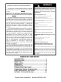
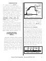
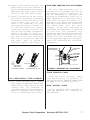
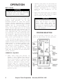
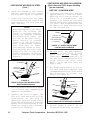
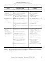
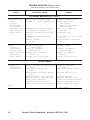
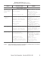
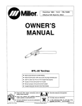
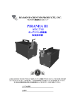
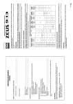
PLEASE VISIT OUR WEB SITE TO DOWNLOAD
SERVICE MANUAL IF NEEDED
!
MANUFACTURER’S LIMITED WARRANTY
This equipment is warranted against defects in materials
and workmanship for a period of two years from the date of
purchase.
EXCEPTION: THE MIG TORCH IS WARRANTED FOR A
PERIOD OF 30 DAYS FROM THE DATE OF PURCHASE.
Should the equipment become defective for such reason,
the Manufacturer will repair it without charge, if it is returned
to the Manufacturer’s factory, freight prepaid. This warranty
does not cover: (1) failure due to normal wear and tear; (2)
consumable parts, such as, but not limited to, torch contact
tips, gas cups and insulating bushings; (3) damage by
accident, force majeure, improper use, neglect, unauthorized repair or alteration; (4) anyone other than the original
purchaser.
THIS LIMITED WARRANTY IS IN LIEU OF ALL OTHER
WARRANTIES, EXPRESS OR IMPLIED. THE MANUFACTURER SHALL NOT BE LIABLE FOR ANY INJURY TO
PERSONS, INCLUDING DEATH; OR LOSS OR DAMAGE
TO ANY PROPERTY, DIRECT OR CONSEQUENTIAL,
INCLUDING, BUT NOT LIMITED TO, LOSS OF USE,
ARISING OUT OF THE USE, OR THE INABILITY TO USE,
THE PRODUCT. THE USER ASSUMES ALL RISK AND
LIABILITY WHATSOEVER IN CONNECTION WITH THE
USE OF THE PRODUCT, AND BEFORE DOING SO,
SHALL DETERMINE ITS SUITABILITY FOR HIS INTENDED USE, AND SHALL ASCERTAIN THE PROPER
METHOD OF USING IT.
SOME STATES DO NOT ALLOW LIMITATIONS ON
HOW LONG AN IMPLIED WARRANTY LASTS, OR THE
EXCLUSIONS OR LIMITATIONS OF INCIDENTAL OR
CONSEQUENTIAL DAMAGES. SO THE ABOVE LIMITATIONS OR EXCLUSIONS MAY NOT APPLY TO YOU. THIS
WARRANTY GIVES YOU SPECIFIC LEGAL RIGHTS, AND
YOU MAY HAVE OTHER RIGHTS WHICH MAY VARY
FROM STATE TO STATE.
WARNING
ARC WELDING CAN BE INJURIOUS TO OPERATOR AND PERSONS IN THE WORK AREA -——
CONSULT INSTRUCTION MANUAL BEFORE
OPERATING.
ELECTRIC SHOCK can kill.
• Do not touch electrodes or other electrically live parts.
• Insulate yourself from work and ground.
• Install and ground machine in accordance with the National
Electical Code and local code(s). Read Operating Manual
before installing or operating.
• Do not operate with protective covers, panels, or guard
removed.
• Disconnect input power before servicing.
• Only qualified personnel should install, use, or service this
equipment.
ARC RAYS can injure your eyes and burn
skin.
• Wear correct eye, ear, and body protection while welding.
FUMES AND GASES can be dangerous to your
health.
• Use enough ventilation and/or exhaust at the arc.
• Keep your head out of fumes.
• Do not breathe fumes.
READ AND UNDERSTAND THE
MANUFACTURER’S INSTRUCTIONS AND
YOUR EMPLOYER’S SAFETY PRACTICES.
See American National Standard Z49.1, “Safety in
Welding and Cutting”, published by the American
Welding Society, 2501 N.W. 7th St., Miami, Florida
33125; OSHA Safety and Health Standards, 29 CFR
1910 available from U.S. Dept. of Labor, Wash.,
D.C. 20210.
TABLE OF CONTENTS
INTRODUCTION .................................................................. 1
SPECIFICATIONS ............................................................... 2
CHECK LIST ........................................................................ 3
INSTALLATION ................................................................... 4
OPERATION ........................................................................ 8
MAINTENANCE ................................................................. 11
TROUBLE SHOOTING CHART ........................................ 13
CONNECTING TIGPAK OR SPOOL GUN ........................ 18
PARTS BREAKDOWN - MIG TORCH .............................. 20
OPTIONS - TIG PAK, SPOOL GUN .................................. 22
Snap-on Tools Corporation
Kenosha, WI 53141-1410
INTRODUCTION
The Snap-On Tools MIG220 is
a
combination welding power
source, wire feed unit, MIG torch
and accessory package designed to
meet the requirements ofthe light to
medium metal fabrication
industries. The unit producesfusion
welds by the Gas Metal ArcWelding
process (GMAW or MIG), onsteel
and aluminum up to 5/16" thick,
using.023" through.045" steel wire
and .025" through 3/64"aluminum
wire with the optional MHG5-A.
(optional liners
must be
purchased to cover given wire
sizes). Heavier sections can be
easily welded using slightly
different techniques.
The number of controls on the unit
has been reduced to assist inexperienced operators to learn MIG
welding. This facilitates rapid set
up for welding various thicknesses
of material requiring various heat
inputs. The HEAT (voltage) control
adjusts the welding voltage and the
WIRE SPEED control adjusts the
speed of the wire feed motor.
THE MIG PROCESS
AS APPLIED TO THE
MIG220
The MIG process uses a bare,
consumable electrode in the form of
spooled wire, which is fed by a
controllable speed feed unit through
the cable and torch to the weld. The
emerging wire and the weld are
shielded by a stream of CO2, Argon,
or a mixture of the two, which
prevents oxidation of the molten
weld puddle. The gas shield enables
high quality welds to be made
without the use of flux, eliminating the need for slag or flux
removal after the weld is completed.
WIRE SPOOL
FEED
ROLLS
MIG
TORCH
POWER SOURCE
+
SHIELDING GAS
REVERSE
POLARITY
(STD.)
_
WORK
FIGURE 1. SCHEMATIC OF MIG PROCESS
The consumable electrode wire
is melted and transferred to the
weld puddle by any of three arc
modes; short
arc
transfer,
globular trans- fer, or spray
arc
transfer.
The MIG220 is
capable of perform- ing all modes
on steel and aluminum.
SHORT ARC OR DIP TRANSFER
Short arc transfer occurs at 12 to
22 arc volts (voltage while welding), depending on wire size. Welding commences as the arc is struck
and a weld pool is formed. The tip
of the electrode wire dips into the
pool and causes a short circuit.
The short circuit current flow
causes a rapid temperature rise in
the electrode wire and the end of
the wire is melted off. An arc is
immediately formed between the tip
of the wire and the weld pool,
maintaining the electrical circuit
and producing sufficient heat to
keep the weld pool fluid. The
electrode continues to feed and
again dips into the pool.
ELECTRODE
WORK
FIGURE 2. SHORT ARC TRANSFER
Snap-on Tools Corporation
Kenosha, WI 53141-1410
1
SHORT ARC OR DIP TRANSFER (Cont.)
DESCRIPTION
This sequence of events is repeated up to 200 times per second.
Short arc transfer is suitable for
positional welding. The heat input
to the workpiece is kept to a
minimum which limits distortion and
makes possible the welding of thin
sheet material.
The
MIG220 consists of a
combination MIG welding power
source and wire feed unit, a
15TG10MIG torch, a fifteen foot
ground cable with ground clamp,
a twenty foot
power
input
cable,
a
gas regulator
flowmeter,
a
torch accessory
kit, and a built-in cyl- inder
rack and industrial wheel kit.
Welder components are cooled by
forced fan cooling.
Welder controls are simple and
clearly marked. The output voltage
is controlled by a twelve position
tap switch, providing twelve voltage selections. Voltages can be
monitored by the voltmeter on the
control panel. Wire feed speed is
controlled by the wire speed potentiometer.
GLOBULAR TRANSFER
Globular transfer occurs at the
intermediate range of 22 to 24 arc
volts, depending on wire size. As
the name implies, the transfer
takes place in the form of irregularly shaped globules. Globular
transfer is useful in cases where a
lower heat input than that of true
spray is required.
ELECTRODE
GAS NOZZLE
SHIELDING GAS
WORK
FIGURE 3. GLOBULAR TRANSFER
SPRAY TRANSFER
Spray transfer occurs at 22 to 28
arc volts, depending on wire size.
The length of the arc is held
constant by the voltage available.
The higher voltage and current
causes the electrode wire to melt
off before touching the workpiece.
The molten metal crosses the gap to
the workpiece in a spray form.
Spray transfer is used in the downhand position and provides higher
deposition rates than short arc
transfer or globular transfer.
ELECTRODE
GAS NOZZLE
SHIELDING GAS
SPECIFICATIONS
PART NUMBER: MIG220
INPUT POWER REQUIREMENTS:
Voltage
208/230 volts AC
Phase
single phase
Frequency
50/60 hertz
Current
34/30 amps
NOTE
This welder draws 20 amps at
100%
Duty
cycle
(185
amps output). A 40 amp 208
or 230 volt
electrical
service
is required for
proper arc start- ing and
full
utilization
of its
maximum output of 220amps.
DUTY CYCLE - OUTPUT POWER:
Welding Current
(NEMA)@ 60% 180 Amps
@ 20% 220 Amps
DUTY CYCLE TIME PERIOD:
WORK
10 minutes
FIGURE 4. SPRAY TRANSFER
2
Snap-on Tools Corporation
OPEN CIRCUIT VOLTAGE:
15 - 37.5 volts DC
Kenosha, WI 53141-1410
SPECIFICATIONS (Cont.)
CHECK LIST
WIRE TYPES:
mild steel,
stainless steel, aluminum,
bronze, flux cored,
flux cored - gasless
Recommended (for steel)
ER70S-6
THE SNAP-ON TOOLS MIG220INCLUDES
THE FOLLOWING:
WIRE SIZES: .023" - .045" steel,
.035" - 3/64" aluminum,
(.023" - 3/64" alum. w/spool gun)
.030" - .035" bronze,
.035' - .045 flux cored
(gas shielded or gasless)
Recommended Size:Aluminum
.035
Others
.030
1- Combination Power Source/Wire
Feeder
1- Cylinder Rack/Industrial Wheel
Kit
1- 15TG10 MIG Torch with adjustable nozzle
1- 20 foot Power Input Cable
1- 10 foot Ground Cable and Clamp
WIRE FEED SPEED RANGE:
10 - 500 inches per minute
SHIELDING GASES:
For Steel
CO2 or Argon/CO2 mix
Recommended (for steel)75% Argon/
25% CO2
For Aluminum, Bronze
Argon
For Stainless Steel
98% Argon/2%Oxygen
For Flux cored
CO2 or
Argon/CO2 mix
DIMENSIONS:
Height
34 in. (86.4
Width
14-1/2 in. (36.8
Depth
35 in. (88.9
Weight
195 lbs. (88.5
1- Gas Regulator/Flowmeter - for
steel or aluminum
1- Nozzle, 1/2 in. orifice (installed on MIG torch)
1- Contact Tip, for .030 in. wire
(installed on MIG torch)
1- ER70S-6-30-3, Sample Spool of
.030 Steel Wire
cm.)
cm.)
cm.)
kg.)
TORCH SPECIFICATIONS
NECK ANGLE:
1- 230PK-1 Accessory Kit
OPTIONAL EXTRAS
RE5-A Range Extender, a wire feed
unit
which
extends
the reach of the MIG220 an
extra 25 feet.
60 degrees
LEAD LENGTH:
10 feet
OVERALL LENGTH:
10 feet
COOLING METHOD:
gas (air)
RATING - DUTY CYCLE:
With Argon/CO2 gas150 amps @ 100%
With CO2 gas
200 amps @ 100%
Snap-on Tools Corporation
50CP-0
50 foot Power Input Cable
(replaces standard 20 foot
power input cable).
MHG5-A
Spool Gun - for welding
aluminum(see page 22)
TIGPAK
Tig Torch Kit - for TIG
welding steel, stainless
steel(see page 22)
Kenosha, WI 53141-1410
3
ITEMS REQUIRED FOR MIG WELDING
WHICH ARE NOT PROVIDED WITH THE
MIG220.
1. Full cover welding helmet with
proper colored lens (shade 9 to 11
depending on operator’s preference).
2. Proper shielding gas and cylinder.
3. Leather welding gloves.
208V
INPUT
1. Remove
2.
SELECTION
the
top
cover.
Locate the contactor switch
which is mounted on top of the
main power transformer (See Figure 5).
4. Electrial Power.
5. Other personal protective
equipment which may vary to
match the welding being performed.
THE MIG220 REQUIRES
A 208 OR 230
SINGLE
WELD POWER
CONTACTOR
CONNECT "208"
TERMINAL FOR
OPERATION ON
208 VOLT INPUT
PHASE, AC, 40 AMP CIRCUIT.
CONNECT "230"
TERMINAL FOR
OPERATION ON
230 VOLT INPUT
INSTALLATION
FRONT OF
MACHINE.
POSITIONING THE UNIT
Locate the unit adjacent to the
welding area and position it so
there is adequate clearance all
around for ventilation and maintenance.
ELECTRICAL SUPPLY
FIGURE 5. INPUT VOLTAGE SELECTIONS
CAUTION
MAKE SURE POWER SOURCE IS
UNPLUGGED BEFORE MAKING INPUT SELECTION CHANGE-OVER.
Ensure that there is a 208 or 230
volt, single phase, 40 amp electrical supply within easy reach of
the unit. The input cable supplied
is 20 feet long. A 50 foot cable is
an optional extra. Attach a suitable plug making sure the green
wire is attached to ground. All
wiring should be performed by a
qualified electrician.
230V INPUT SELECTION
3. Attached to the power source’s
contactor is one (2) two position plug which allows easy
selection of input voltages of
either 208 or 230 volts.
4. Remove the one (1) plug labeled
230V and connect the one (1) plug
labeled 208V.
1. Factory selected no change is
needed.
5. Reattach the top cover of the
machine. Voltage input selection is now complete.
4
Kenosha, WI 53141-1410
Snap-on Tools Corporation
SHIELDING GAS CONNECTIONS
1. Place a cylinder of the appropriate shielding gas in the rack
at the rear of the machine and
secure it with the chain provided. See recommended gases on
page 3.
2. Rapidly open and close the cylinder valve. This will purge
dust and foreign matter from the
valve.
CAUTION
Take care to point the valve
outlet away from yourself or
other people, as escaping
high pressure gas may be
dangerous.
3. Attach the gas regulator - flowmeter supplied with this unit,
to the cylinder valve using a
suitable wrench.
NOTE
If this unit is to be used
with 100% CO2 shielding gas,
an optional gas regulator
coupler is required.
4. Fit the gas hose from the welding
machine to the regulator outlet
fitting and tighten it with a
wrench. Open the cylinder valve.
When welding steel, the gas flow
rate is 30 CFH. When welding
aluminum, the gas flow rate is 40
CFH.
NOTE
The MIG220 must be turned
"ON" and the MIG torch
trigger depressed, before the
gas flow rate can be adjusted.
TORCH CONNECTION
1. Open the access door of the
machine to its fullest extent.
2. Back out the thump screw
located on the drive assembly
mounting bracket inside the machine. Insert the MIG into the
torch panel month on the front
panel and
TIGHTEN THE
THUMB SCREW SECURELY AND
CHECK OFTEN.
MIG
TORCH
TORCH
PANEL
MOUNT
PRESSURE
ROLL
FLOW TUBE
INDICATES
FLOW RATE
IN C.F.H.
GAUGE INDICATES
TANK
PRESSURE
GAS FLOW
ADJUSTING
KNOB
THUMB
SCREW
DRIVE ROLL
DRIVE ASSEMBLY
FIGURE 7. TORCH CONNECTION
OUTLET
FITTING
TO
WELDING
MACHINE
INLET
FITTING
TO
TANK
FITTING AND THREADING THE ELECTRODE
WIRE - ALWAYS USE ER70S-6 WELDING
WIRE.
1. Remove the wire spool clip from
the spool hub.
FIGURE 6. GAS FLOW ADJUSTMENT
Snap-on Tools Corporation
(continued on following page)
Kenosha, WI 53141-1410
5
FITTING AND THREADING THE ELECTRODE
WIRE (Cont.)
2. Unpack the spool of welding wire
from its protective packaging.
3. Place the spool of ER70S-6 welding wire on the hub ensuring that
the hole in the spool flange
lines up with the locating pin on
the hub. The wire is fed off the
bottom of the spool.
CAUTION
Look for and remove any wire
protruding from the center
of the spool. The protruding
wire is electrically HOT
during welding and must not
touch the machine.
4. Replace the spool clip on the
hub.
5. Unlatch the pressure roll arm
and swing it open.
6. Make sure the double v-groove
drive roll is installed to match
the wire size. To change the wire
size setting, remove the drive
roll, turn it over and reinstall
it on the drive motor shaft.
B
"B" SIDE FACING IN FOR
.023" - .035" STEEL WIRES
7. Release the wire from the spool
and trim off the kinked end with
wire cutters. The wire must be
straight when it enters the
inlet guide.
8. Thread the electrode wire through
the inlet guide, over the feed
roll and into the torch liner.
Ensure that the wire locates in
the feed roll groove. Do not
allow the wire on the spool to
loosen.
9. Close and relatch the pressure
roll arm.
10.Stretch the torch cable straight
out in front of the machine
making sure there are no kinks.
Remove the nozzle and contact
tip from the torch.
11.Turn on the circuit breaker on
the front of the machine. The
cooling fan will start and the
"ON" indicator light will illuminate. Set the HEAT control
switch to "4" and the WIRE SPEED
control to "7". Pull the trigger
on the MIG torch. The wire feed
system will start and wire will
be fed through the cable liner
and torch. If the wire does not
feed, or appears to slip, tighten
the pressure roll arm adjusting
nut. Feed the wire until it
protrudes from the front of the
torch approximately six inches.
CAUTION
C
"C" SIDE FACING IN FOR
.040" - .045" STEEL WIRES
AND 3/64" ALUMINUM WIRES
3045DR Large Drive Roller
FIGURE 8. DOUBLE GROOVE DRIVE ROLL
6
Snap-on Tools Corporation
Keep hands and face away
from the front of the torch
and do not allow the wire to
contact ground. The wire is
electrically HOT when the
torch trigger is actuated.
Kenosha, WI 53141-1410
12.Install the contact tip over the
protruding wire and tighten it
firmly using a proper size wrench.
Make sure the tip is the correct
size for the wire being used.
13.Install the nozzle on the torch.
For steel, the contact tip should
be flush or stick out up to 1/16
inch beyond the end of the
nozzle. For aluminum, the contact tip should be recessed 1/8
to 3/8 inch inside the nozzle.
Using wire cutters, trim off the
wire so the stickout is approximately 1/4 inch for steel or 1
inch for aluminum. For aluminum,
the end of the wire should be
bent over so it does not JAM into
the work. This is called a
"scratch start". See Figure 9.
WIRE FEED PRESSURE ROLL ADJUSTMENT
The wire feed pressure roll is
adjusted to the proper setting at
the factory, prior to delivery. It
may be necessary to readjust the
setting as components "seat in" or
when changing to a different diameter wire. To check for proper roll
pressure, hold the torch in one hand
and the wire between two fingers of
the other hand. Pull the torch
trigger. If the wire continues to
feed when firm pressure is applied
to the wire, the pressure roll
adjusting nut should be backed off
until the feed rolls start to slip.
If the wire will not feed with very
little pressure applied, the pressure roll adjusting nut should be
tightened.
PRESSURE ROLL
ADJUSTING NUT
PRESSURE
ROLL
PRESSURE
ROLL ARM
1"
1/4"
STICK-OUT
STICKOUT
FOR STEEL:
CONTACT TIP
FOR ALUMINUM:
FLUSH WITH NOZZLE
TIP RECESSED 1/8" - 3/8"
DRIVE
ROLL
FIGURE 10. PRESSURE ROLL ADJUSTMENT
TORCH SELECTOR CABLE
FIG. 9. WIRE STICKOUT - STEEL, ALUMINUM
14.For steel welding only, spray
anti-spatter compound inside the
nozzle and on the outside of the
contact tip. For aluminum or
stainless steel welding, NO antispatter compound can be used as
it will contaminate the weld.
Snap-on Tools Corporation
Plug the torch selector cable
into the Positive (+) terminal on
the machine(see PROCESS SELECTION
on page 8 for further details).
WORK (GROUND) CABLE
Uncoil the Work cable and plug it
into the negative (-) terminal on
the machine.
Kenosha, WI 53141-1410
7
OPERATION
DUTY CYCLE
CAUTION
CONTINUAL EXCEEDING OF THE DUTY
CYCLE OF THIS (OR ANY) WELDING
MACHINE CAN CAUSE DAMAGE.
The Duty Cycle of a welding power
source is a percentage of a ten (10)
minute time period. It is the
maximum amount of time the power
source can be operated at a given
output without sustaining possible
damage due to overheating. A 60%
Duty Cycle means the welding machine can be operated at its rated
amperage for six (6) minutes out of
ten. The machine must be allowed to
cool (machine ON, fan running, but
not welding) for the remaining four
(4) minutes. Operating the machine
at a higher output requires that the
duty cycle percentage be lowered.
The following operating instructions and detailed setup procedures
enable an operator without previous
experience to produce quality fusion welds. It is recommended that
an operator without prior experience with this equipment, first
practice on scrap metal of the same
type and thickness as the material
to be welded.
OPERATING SEQUENCE
1. Make sure that the pieces of
metal to be welded are free of
grease, dirt, paint and scale.
Use a wire brush to remove paint
and scale. Paint must be completely removed to bare metal.
Grease and oil could burn and
cause a fire or safety hazard.
Failure to clean the metal properly will result in erratic and
porous welds.
8
Snap-on Tools Corporation
2. Install the unit as directed in
the installation instructions
and make sure the ground clamp is
firmly attached to a cleaned
area on the workpiece to be
welded.
3. Open the shielding gas cylinder
valve. Press the torch trigger
and listen for gas flow.
CAUTION
The welding wire will feed
when the trigger is actuated. Take care that the
wire is not directed to hit
yourself or anything that is
grounded to the ground wire
on the welder.
PROCESS SELECTION
The following controls are located on the front of the machine.
A.
WIRE
SPEED
F.
TORCH
PANEL
MOUNT
B.
HEAT
(VOLTAGE)
CONTROL
C.
VOLTMETER
G.
TORCH
SELECTOR
CABLE
D.
CIRCUIT
BREAKER
H.
(+)POSITIVE
TERMINAL
E.
"ON"
INDICATOR
LIGHT
I.
(-)NEGATIVE
TERMINAL
FIGURE 11. FRONT PANEL
Kenosha, WI 53141-1410
A. WIRE SPEED
Potentiometer controls speed of
wire drive motor to give wire
speed range of 10 to 500 inches
per minute.
B. HEAT (VOLTAGE) CONTROL
Twelve position switch adjusts
welder output voltage.
C. VOLTMETER
Indicates open circuit voltage
when torch switch is actuated
and arc voltage while welding.
D. CIRCUIT BREAKER
Primary power switch and overload protection device.
E. "ON" INDICATOR LIGHT
Illuminates when the circuit
breaker on the machine is "ON".
F. TORCH PANEL MOUNT
Combination power output, contactor switch connection, gas
supply connection, and wire feed
output in a single unit.
G. TORCH SELECTOR CABLE
Plugs into (+) positive terminal
for standard welding operation
or (-) negative terminal for
straight polarity welding on
very light sheet metal, or for
using flux cored gasless wire.
H. +(POSITIVE) TERMINAL
Positive output terminal from
the welder DC power source. The
torch selector cable is plugged
into this terminal for standard
welding operation. The ground
cable can be plugged into this
terminal for straight polarity
welding on very light sheet
metal, or for using flux cored
gasless wire.
I. -(NEGATIVE) TERMINAL
Negative output terminal. The
ground cable is plugged into
this terminal during standard
welding operation. The torch
selector cable can be plugged
into this terminal for straight
polarity welding on very light
sheet metal, or for using flux
cored gasless wire.
WELDING
Optimum control settings will
vary according to the thickness of
the metal, the type of joint,
operator preference, etc. Best results can be obtained through experience with the welding machine or
by making trial welds. Select some
sample material of the same type and
thickness as the material to be
welded. Set the welding controls
for optimum results using the sample
material and weld until experience
is gained using the unit.
CONTINUOUS WELDING ON STEEL
1. Trim the electrode wire to leave
approximately 1/4 inch stickout
beyond the end of the contact tip
and install the welding nozzle.
The contact tip should be flush
or stick out up to 1/16 inch
beyond the end of the nozzle.
NOZZLE
CONTACT TIP
(FLUSH TO
1/16" STICKOUT)
ELECTRODE WIRE
(1/4" STICKOUT)
FIGURE 12.
NOZZLE ADJUSTMENT FOR WELDING STEEL
(continued on following page)
Snap-on Tools Corporation
Kenosha, WI 53141-1410
9
CONTINUOUS WELDING ON STEEL
(Cont.)
2. Spray the inside of the nozzle
and the outside of the contact
tip with anti-spatter compound.
3. Locate the torch over the joint
to be welded with the contact tip
approximately 3/4 inch from the
work surface.
NOTE
When welding steel, the ideal
position for holding the
torch is inclined approximately 30 degrees towards
the direction of travel. The
arc can to be seen easily,
which results in greater
control of the weld pool.
Most right-handed weldors
move from left to right.
This method, known as forehand welding, provides a gas
shield for the cooling weld
puddle and helps in obtaining an oxidation free weld
deposit.
30 DEGREES
DIRECTION
OF TRAVEL
SHIELDING
GAS
WORK
CONTINUOUS WELDING ON ALUMINUM
(Nylon liner and 100% Argon shielding
gas are required)
USE
1. Trim the electrode wire, leaving
approximately 1 inch stickout.
Bend the wire over as shown, to
allow for a scratch start. The
contact tip should be recessed
inside the nozzle approximately
3/8 inch. This helps prevent the
welding wire from burning back
to the contact tip.
NOZZLE
CONTACT TIP
(RECESSED 3/8")
ELECTRODE WIRE
(1" STICKOUT)
FIGURE 14. NOZZLE ADJUSTMENT
FOR WELDING ALUMINUM
2. DO NOT spray any anti-spatter
material on the torch or base
metal and DO NOT attempt to
lubricate the aluminum wire in
any way. Weld contamination will
occur unless the wire, base
metal, torch and work area are
kept clean.
3. Bring the torch nozzle to 1/2 to
5/8 inch from the workpiece. The
recommended position of the torch
and direction of travel are
shown in Figure 15.
FIGURE 13.
TORCH POSITION FOR WELDING STEEL
- RIGHTHANDED WELDOR
4. Use a welding helmet with a shade
9 to 11 filter lens, depending on
operator preference.
10 DEGREES
DIRECTION
OF TRAVEL
SHIELDING
GAS
WORK
5. Squeeze the torch trigger. The
wire will feed and an arc will be
established. As the weld is
deposited, move the torch slowly
along the weld seam at a constant
speed, while maintaining a constant arc length and a constant
tip-to-work distance.
4. Follow steps 4 and 5 as in
"Continuous Welding on Steel".
10
Kenosha, WI 53141-1410
Snap-on Tools Corporation
FIGURE 15.
TORCH POSITION FOR WELDING ALUMINUM
OPERATING HINTS
BURN BACK
In the event the welding wire
burns back into the contact tip:
1. Remove the nozzle from the torch.
2. Unscrew the contact tip from the
gas diffuser using a pair of
pliers as the tip will be very
hot.
3. Free the wire from the contact
tip and clean the end of the tip
so the new wire will slide
smoothly through the hole. DO
NOT use a drill or reamer to
clean the hole as they will
enlarge it and cause an erratic
arc. Replace the contact tip if
it is badly damaged.
4. Install the contact tip in the
torch and tighten it firmly with
an appropriate wrench.
5. Reinstall the torch nozzle.
6. If the wire continues to burn
back, check for erratic wire
feed, or speed up the wire by
increasing the WIRE SPEED control setting or reducing the
HEAT control setting.
SPATTER
Before beginning to weld and
periodically during welding, the
torch nozzle must be removed and the
spatter (small globules of melted
metal) cleared from the inside of
the nozzle and the outside of the
contact tip and the gas diffuser.
Spatter buildup between the contact
tip and the nozzle can cause a short
circuit and consequently, failure
of the torch or welding machine.
The frequent use of anti-spatter
spray will help prevent the adherence of spatter to the torch components.
Snap-on Tools Corporation
NOTE
DO NOT use any anti-spatter
spray when welding aluminum or
stainless steel.
Restricted gas flow, holding the
torch too far from the work piece,
and the use of CO2 gas rather than
75% Argon - 25% CO2 will increase
the spatter levels.
MAINTENANCE
To ensure that this equipment
maintains its operating efficiency,
the following maintenance schedule
and procedures are recommended.
These routines should be performed
regularly by the operator.
REGULARLY - Usage and shop conditions determine frequency.
1. Remove and clean the torch nozzle
and contact tip. The use of antispatter spray will reduce the
adherence of spatter and makes
its removal easier.
2. Blow out the torch liner prior to
the installation of each new
spool of wire. The contact tip
and gas diffuser must be removed, but it is not necessary to
remove the liner.
3. If the torch cable assembly is
bent severely, a kink may develop in the steel liner. This
can cause wire feeding problems
so a new liner should be installed.
WEEKLY
1. Remove dirt and dust from the
wire feed compartment. Use low
pressure dry compressed air.
(continued on following page)
Kenosha, WI 53141-1410
11
MAINTENANCE (Cont.)
2. Remove dirt and metal deposits
from the grooves in the feed
roll. If the grooves are badly
worn, the feed roll should be
replaced. If the pressure roll
does not turn freely, it should
be replaced.
3. Check all gas fittings for leaks.
Tighten or repair as required.
In the event of the failure of any
part of this equipment, contact
your Snap-On Tools representative
for replacement parts and service.
When ordering parts from Snap-On
Tools Corporation, order numbers
should be preceded by "CKS".
WARNING
EVERY SIX MONTHS
DO NOT lift the unit when a gas
cylinder is installed or attached.
1. Disconnect the welder from its
main power supply.
DO NOT weld on any item that
has a common electrical ground.
2. Remove the machine’s side panels.
DO NOT operate the unit with
the side panels removed. Overheating will occur.
3. Using low pressure dry compressed air, remove dust and
dirt from all components.
DO NOT weld upon the case of
the welding machine.
4. Check for loose or frayed wiring. Particularly check welding
current wire connections.
ONLY a qualified electrician
should perform work inside the
welding machine.
5. Replace torch liner if necessary.
ALWAYS wear protective clothing, leather gloves and a full
cover welding hood while welding.
RECOMMENDED
CUSTOMER SPARE PARTS
The Snap-On Tools MIG220 is a
machine of proven design
and reliability. Following is a
list of consumable items recommended as spare parts for this unit.
contact tips..........M3-T30,etc.
gas nozzles ..............M3T-N50
nozzle insulators...........M3T-B
gas diffusers...............M3T-D
steel liner (.020-.030)...M103L-B
steel liner (.035-.045)...M104L-N
DO NOT weld in a closed in
area. Proper ventilation is a
necessity, or a fresh air
supplied hood should be worn.
WHEN welding near combustibles,
a helper or "watcher" should
stand by with a fire extinguisher or other fire protective device.
NEVER weld on a closed vessel
or one that has contained
combustibles.
IF IN DOUBT - DON’T DO IT!
BE SAFE - DON’T BE SORRY!
12
Snap-on Tools Corporation
Kenosha, WI 53141-1410
TROUBLE SHOOTING (SYMBOL*)
FOR TECH. SERVICE, CALL TOLL-FREE 1-800-232-9353
The Trouble Shooting Chart is a guide in identifying and correcting
possible troubles which may occur when operating this equipment.
FAULT
POSSIBLE CAUSE
REMEDY
EQUIPMENT MALFUNCTION
No main power,
fan does not
operate,
"on" indicator
light is off.
MIG220 switch is "OFF".(CB1) Turn switch "on".
Wall breaker is "tripped".
Reset wall breaker.
Reset or replace
"Open" circuit breaker
on MIG220. (CB1)
breaker.
Tighten or repair
Loose or broken connection
in power input circuit.
connection.
Main power on,
torch
trigger
activated,
no response.
MIG torch unplugged.
Faulty trigger switch.
Fault in torch cable.
(S1)
Loose or broken connection
on wiring harness.
Wire feed motor unplugged.
Plug in MIG torch.
Replace micro switch.
Check torch cable
for continuity.
Check or repair
connections.
Plug in motor.
(RC3)
Faulty control transformer.
Check for 28VAC output.
(T2)
Main power on,
torch
trigger
activated,
no wire feed
but contactor
operates &
gas flows.
Pressure roll arm unlatched. Latch arm & add tension.
"Slippage" at drive rolls.
Increase drive roll
tension. See page 7.
Wire path restricted.
Clean path or replace
torch liner.
5 amp mini breaker is
Reset or replace
breaker.
tripped. (CB2)
Calibrate wire feed
Wire feed circuit board
circuit board. See
needs calibrated.
page 17.
Replace circuit board.
Defective wire feed
circuit board. (PC1)
Faulty wire feed motor
Repair or replace
or connection. (M)
faulty item.
Check motor on a
12VDC battery.
Sand points or replace
Faulty motor relay. (CR1)
relay.
Loose or broken connection. Tighten or repair
connection.
(continued on following page)
(SYMBOL*) -
USE THIS IDENTIFIER, ALONG WITH THE SCHEMATIC DIAGRAM FOUND IN THE SERVICE
MANUAL, FOR TROUBLE-SHOOTING PURPOSES.
Snap-on Tools Corporation
Kenosha, WI 53141-1410
13
TROUBLE SHOOTING (Cont.)
(SYMBOL*)
FOR TECH. SERVICE, CALL 1-800-232-9353
FAULT
POSSIBLE CAUSE
REMEDY
EQUIPMENT MALFUNCTION (Cont.)
Main power on,
torch
trigger
activated,
no welding
current, but
gas flows &
wire feeds.
Loose torch thumb screw.
Broken or loose connection.
Unplugged or faulty power
contactor switch. (W)
208/230V selector wire off.
Tighten thumb screw.
Check cables for
continuity.
Repair or tighten
connections.
Plug in or replace
switch.
Reattach wire.
(W)
"Opened" thermal switch.
(TP1)
Faulty diodes.
(D1-D4)
Torch
trigger
activated,
no gas flow,
but contactor
operates &
wire feeds.
No shielding gas
- tank empty.
Loose or broken
connections.
Faulty Gas solenoid
valve. (GS)
Clogged gas flow path.
Allow unit to cool, then
retry.
Check diodes. See page
16.
Replace tank.
Tighten or repair
connections.
Repair or replace
valve.
Locate & clean clog.
FAULTY WELDS
"Jerky" or
"slipping"
wire feed.
Worn , kinked or dirty torch
liner.
Wire spool turns too
hard.
Worn double v-groove drive
roll.
Weak pressure roll spring.
Worn or dirty contact tip.
Worn inlet guide(s).
Sticking pressure roll.
Feed roll tension incorrect.
Clean or replace
liner.
Lubricate spool shaft.
Replace drive roll.
Replace spring.
Replace contact tip.
Clean or replace guides.
Replace pressure roll.
Adjust feed roll ten-
sion.
See page 7.
14
Snap-on Tools Corporation
Kenosha, WI 53141-1410
TROUBLE SHOOTING (Cont.) (SYMBOL*)
FOR TECH. SERVICE, CALL TOLL-FREE 1-800-232-9353
FAULT
POSSIBLE CAUSE
REMEDY
FAULTY WELDS (Cont.)
"Birdnesting"
(Wire wrapping
around drive
rolls)
Excessive feed roll tension. Reduce tension. See page
7.
Poor alignment.
Make sure wire is
properly aligned
across roller.
Oversize contact tip.
Replace contact tip with
correct size.
"Cold" weld
puddle.
Incorrect machine settings.
Incorrect shielding gas.
Excessive wire stick-out.
Poor connections.
Faulty diode.
(D1-D4)
Heavy spatter.
Incorrect machine settings.
Incorrect shielding gas.
Excessive wire stick-out.
Porous welds.
No shielding gas.
Not enough gas flow.
Increase heat & wire
speed.
Replace with proper gas.
Hold torch closer to
work.
Check and tighten all
connections.
Test diodes, replace
faulty diode(s). See
page 16.
Increase heat, decrease
wire feed speed.
Replace with proper gas.
Hold torch closer to
work.
Turn on gas.
Check hoses for leaks,
make sure cylinder is
not empty. Increase
flow rate.
Change wire.
Replace solenoid.
Contaminated wire.
Faulty gas solenoid.
(GS)
Incorrect electrode wire.
Contaminated base material.
(SYMBOL*) -
Use correct wire.
Clean or etch base
material.
USE THIS IDENTIFIER, ALONG WITH THE SCHEMATIC DIAGRAM FOUND IN THE SERVICE
MANUAL, FOR TROUBLE-SHOOTING PURPOSES.
Snap-on Tools Corporation
Kenosha, WI 53141-1410
15
TESTING AND REPLACING DIODES
Silicon diodes have proven to be
highly reliable. However, weld spatter build-up in the torch can short
out and cause diode overload and
consequent failure. The following
information is provided as a guide
should a failure be suspected.
Silicon diodes exhibit two main
fault conditions:
1. "Open Circuit" - causes a reduction in welder output.
4. Connect the headlight bulb to
one end of the diode. Test for
electrical flow in both
directions as follows. First,
test by connecting a lead
from the battery positive
(+) terminal to the light
bulb and a lead from the
battery negative (-) terminal to
the other end of the diode. Test
again by reversing the connections. (See Figure 16.) The
headlight bulb should light
with the current flow in one
(1) direction only - not both.
2. "Short Circuit" - causes the
circuit breaker to trip.
12 VOLT
HEADLIGHT
BULB
If a fault is suspected, the diode
may be tested as follows:
1. Remove the top connection of
each diode to be tested.
2. Using a Volt-Ohm Meter set on
diode or 2K, check for
continuity through the diode
in both directions. If there is
no continuity in either
direction, the diode is in
"open circuit" condition and
must be replaced. If there is
continuity in both directions,
the diode is in "short circuit"
condition and must be replaced.
If there is continuity in one
direction only, the diode is
functioning properly.
3. If all the diodes check out
satisfactorily with the VoltOhm Meter, a load check must be
made using a twelve volt battery
and a twelve volt headlight
bulb.
CAUTION
NEVER use a "megger" or a
high voltage device to test
a diode.
16
Snap-on Tools Corporation
+
DIODE
-
12 VOLT
BATTERY
12 VOLT
HEADLIGHT
BULB
+
DIODE
-
12 VOLT
BATTERY
FIGURE 16.
DIODE LOAD CHECK CONNECTION DIAGRAM
- TEST FOR FLOW IN BOTH DIRECTIONS
5. When replacing diodes, it is
very important that a heat conductive compound (Radio Shack
#276-1372) be used where the
diode makes contact with the
aluminum heat sink. Do not grease
the threads on the diode.
Kenosha, WI 53141-1410
WIRE FEED CALIBRATION
Due to INPUT LINE VOLTAGE variations supplied to the welding machine. The WIRE FEED SPEED should be
checked for proper operation.
TO CHECK
1. Remove any tension on the drive
roll.
RESISTOR
2. Turn the wire speed dial (on the
front of the machine) to "0".
3. Activate the torch trigger.
4. The bottom drive roll should
rotate very slowly(non-jerky).
5. If this proves to be true, no
adjustment is required.
IF ADJUSTMENT IS REQUIRED
1. Remove the top cover assembly
from the unit.
2. Locate the printed circuit board.
3. Referring to Figure 17, locate
the trim resistor, this is located in the upper right hand
corner of the wire feed PC board.
4. Turn the wire speed dial (on the
front of the machine) to "0".
FIGURE 17. WIRE FEED PC BOARD
7. Rotate the trim resistor, back
and forth, until the bottom
drive roll moves.
8. Calibrate so the bottom drive
roll rotates very slowly (nonjerky).
5. Remove any tension on the drive
roll.
9. If calibrated correctly the wire
speed dial (on the front of the
machine) should affect the speed
of the drive roll from "0" thru
"10".
6. Activate the torch trigger.
10.Adjustment is now complete!
Snap-on Tools Corporation
Kenosha, WI 53141-1410
17
CONNECTING TIGPAK OR SPOOL GUN
CHANGING FROM STANDARD MIG OPERATION
TO TIGPAK OPERATION
1. Unplug the wire feed motor plug
from the function receptacle.
2. Unplug the torch selector cable
and the ground cable from the
welder front panel.
3. Plug the TIGPAK torch power
cable into the negative (-) weld
connector and plug the ground
cable into the positive (+) weld
connector. This provides straight
polarity current as required
for TIG welding.
4. Plug the TIGPAK torch switch
cord into the welder function
receptacle.
5. Attach the TIGPAK torch gas hose
directly to the gas regulator.
NOTE
Make sure the regulator is
connected to a cylinder of
the proper shielding gas pure argon for TIG welding.
6. Follow the operating instructions in the TIGPAK manual (Form
WC5228).
7. To change back to MIG operation,
reverse the procedure.
4. Install the thread cap (removed
in step 1) on the "MIG TORCH"
fitting to prevent dirt and
contaminants from entering the
unused gas line.
5. Unplug the wire feed motor plug
from the function receptacle.
6. Plug the MHG5-A spool gun control cable plug into the welder
function receptacle.
7. Remove the torch selector cable
from the welder positive (+)
weld connector.
8. Plug the MHG5-A gun cable fitting into the welder positive
(+) weld connector.
NOTE
Make sure the gas regulator
and welder gas hose are
connected to a cylinder of
the proper shielding gas 100% argon for aluminum
welding; 75% argon + 25% CO2
for steel welding. 98% argon
+ 2% O2 is recommended for
stainless steel welding.
9. Follow the operating instructions in the MHG5-A manual (Form
WC5385).
10.To change back to standard MIG
operation, reverse the procedure.
CHANGING FROM STANDARD MIG OPERATION
TO SPOOL GUN OPERATION
All current model MIG machines
are equipped with bulkhead gas
fittings for quick and easy
changeover from standard MIG operation to spool gun operation.
1. Remove the thread cap from the
"SPOOL GUN" fitting.
2. Unscrew the selector hose from
the "MIG TORCH" fitting.
3. Move the selector hose to the
"SPOOL GUN" fitting and tighten.
18
Snap-on Tools Corporation
WIRE FEED
MOTOR
BULKHEAD
FITTINGS
WIRE FEED
MOTOR PLUG
(PLUGGED INTO
FUNCTION
RECEPTACLE)
LABEL
THREAD
CAP
SELECTOR
HOSE
FIGURE 18. BULKHEAD CONNECTIONS
Kenosha, WI 53141-1410
M.I.G. TORCH LINER INSTALLATION
(steel only)
The MIG torch liner provided with
the MIG220 is designed
for wire diameters from .030 thru
.045. If smaller wire diameters are
to be fed and or there is a problem
(i.e. clog, kink, etc.), a liner
change is required.
Following is a step by step guide
to aid in liner removal and installation.
NOTE
When removing the welding wire
from the MIG torch, care should
be taken to avoid the wire from
uncoiling from the wire spool.
GAS SEAL
3/4"
LINER
STICKOUT
FIGURE 19. LINER STICKOUT
4. Install the new liner into the
MIG torch assembly, until gas
seal seats flush with the connector plug.
5. Tighten set screw. (Do not overtighten), refer to FIG. 20.
SET SCREW
3/4"
CONNECTOR
PLUG
REMOVING OLD LINER
1. Remove torch assembly from the
welding machine.
2. Place torch assembly on a flat
surface, making sure torch is
laying straight as possible.
3. Remove nozzle, bushing insulator, contact tip and gas diffuser from the front end of the
torch assembly.
4. Loosen set screw located on the
connector end of the torch assembly (see FIG. 20).
5. Grip the liner and gas seal
firmly, then pull. The liner
should easily slide from torch
assembly.
INSTALLING NEW LINER
1. Remove the new liner from the
package.
2. Uncoil liner and lay the liner
parallel next to the MIG torch
assembly.
3. Adjust the liner stickout length
to 3/4" as shown in FIG. 19.
Snap-on Tools Corporation
FIGURE 20. TORCH CONNECTOR END
6. Following the diagram in FIG.
21, measure out 1 1/4"+ from the
neck assembly and cut off the
protruding liner.
7. Debur the cutoff end of the liner
to insure unobstructed wire feed.
1 1/4+"
NECK
ASSEMBLY
PROTRUDING
LINER
FIGURE 21. TORCH FRONT END
8. Install the gas diffuser and
contact tip of proper wire size,
tighten with a wrench.
9. Install the bushing insulator
onto the gas diffuser. Spray the
"O" rings with anti-spatter compound for lubrication.
10.Install the TWIST-ON adjustable
nozzle and twist the nozzle
during the installation. Turn to
Page 7 for correct nozzle adjustment.
Kenosha, WI 53141-1410
19
PARTS BREAKDOWN - 15 SERIES MIG TORCH
TG STYLE FRONT END - STANDARD
WIRE SIZE
CONTACT TIP
.020 - .025 inch
.030 inch
.035 inch
.040 - .047 inch
M3-T25
M3-T30
M3-T35
M3-T45
GAS DIFFUSER
NOZZLE
M3T-D
M3T-N50
(1/2" I.D.)
INSULATOR
INSULATOR O-RING
M3T-B
(includes o-rings)
M3T-BR
(3 reqd.)
(1-7/16"
length)
SPECIAL APPLICATION PARTS FOR TG STYLE FRONT END
SHORT CONTACT TIP (1-1/4" length)
LARGER ORIFICE
SPOT WELDING NOZZLES
- For Spray Arc Welding
NOZZLE
Standard Nozzle
Low Amp Nozzle
WIRE SIZE
PART NUMBER
STYLE
PART NUMBER
PART NUMBER
.020 - .025 inch
M3-ST25
Straight Nozzle
Flat Spot
M3T-NS1
M3T-NLAS1
.030 inch
M3-ST30
(3/4 “ I.D.)
Inside Corner
M3T-NS2
M3T-NLAS2
.035 inch
M3-ST35
M3T-N75
Outside Corner
M3T-NS3
M3T-NLAS3
.040 - .047 inch
M3-ST45
Irregular (grind to shape)
M3T-NS4
M3T-NLAS4
SG STYLE FRONT END - OPTIONAL
WIRE SIZE
CONTACT TIP
.020 - .025 inch
.030 inch
.035 inch
.040 - .047 inch
M3-T25
M3-T30
M3-T35
M3-T45
GAS DIFFUSER
NOZZLE ASSEMBLY
CUP
NOZZLE BODY
INS. BUSHING
M3-D
M3-NA50
M3-C50
(1/2" I.D.)
M3-NB
M3-B
(1-7/16"
length)
SPECIAL APPLICATION PARTS FOR SG STYLE FRONT END
SHORT CONTACT TIP (1-1/4" length)
LARGER
EXTRA LENGTH FRONT END
- For Spray Arc Welding
ORIFICE
1/2" Longer
1" Longer
WIRE SIZE
PART NUMBER
CUP
PART NUMBER PART NUMBER
CUP (1/2" I.D.)
M3-C50L
M3-C50XL
.020 - .025 inch
M3-ST25
Flared
CONTACT TIP
.030 inch
M3-ST30
Cup
.020 - .025 inch
M5-T25
M5-LT25
.035 inch
M3-ST35
(5/8" I.D.)
.030 inch
M5-T30
M5-LT30
.040 - .047 inch
M3-ST45
M3-C62
.035 inch
M5-T35
M5-LT35
.040 - .047 inch
M5-T45
M5-LT45
SPOT WELDING FRONT END
PART NUMBER
INS. BUSHING
M3H-B
NOZZLE NUT
M3H-NN
SPOT NOZZLE
Flat Spot
M3H-NS1
Inside Corner
M3H-NS2
Outside Corner
M3H-NS3
Irregular
M3H-NS4
XG STYLE FRONT END - OPTIONAL - RECOMMENDED FOR ALUMINUM WELDING
WIRE SIZE
CONTACT TIP
.035 inch
.040 - .047 inch
M5-T35
M5-T45
GAS DIFFUSER
NOZZLE ASSEMBLY
CUP
NOZZLE BODY
INS. BUSHING
M35-D
M35-NA62
M5-C62
(5/8" I.D.)
M5-NB
M5-B
(1-15/16"
length)
SPECIAL APPLICATION PARTS FOR 3-5G STYLE FRONT END
LARGER ORIFICE CUP: Straight Cup (3/4" I.D.) ....... M5-C75
SPECIAL FRONT END FOR GASLESS WIRES - OPTIONAL
INSULATED CONTACT TIP (Tip screw directly into torch neck - no gas diffuser is required) (1-15/16" length)
WIRE SIZE
PART NUMBER
.040 - .047 inch
M5HGL-045
LINERS & SEALS - FOR STEEL WELDING
WIRE
SIZE
ORDER NUMBER
TORCH
LENGTH LINER W/SEAL
SEAL ONLY
.020-.030 inch
10 feet
M103L-B
M3LS-B (Blue)
.035-.045 inch
10 feet
12 feet
M104L-N
M124L-N
M4LS-N (Natural)
LINERS & SEALS - FOR ALUMINUM WELDING
ORDER NUMBER
WIRE
SIZE
TORCH
LENGTH
.035 inch
3/64 inch
LINER
W/SEAL
SEAL
ONLY
HEATSHIELD
ONLY
10 feet
M103AL
M3-6ALS
M3-THS
10 feet
M104AL
M3-6ALS
M3-THS
FIGURE 22. CONSUMABLE PARTS
20
Snap-on Tools Corporation
Kenosha, WI 53141-1410
PARTS BREAKDOWN - 15 SERIES MIG TORCH (Cont.)
PART NO. DESCRIPTION (SYMBOL)
M3-402
TORCH NECK GROUP
M3-101B ..... TORCH NECK *
M3-112 ....... NECK INSULATOR
M3-119 ....... LOCK SCREW - SWITCH HOUSING
M3-120 ....... FERRULE *
M3-402
M1-401
M3-200B ..... SWITCH ASSEMBLY
CONSISTING OF:
M3-201B ..... SWITCH HOUSING
M3-203 ....... SWITCH SCREW (2 REQUIRED)
M3-211K....... SWITCH (S1)
TRIGGER - WITH ADJUSTING SCREW
TRIGGER PIN
TRIGGER SPRING
TORCH NECK GROUP
M3-112
M3-119
QUICK CONNECTOR GROUP
M3-120 ....... FERRULE *
M3-301A ..... CONNECTOR HOUSING
M3-305A ..... CONNECTOR STEM *
M3-306 ....... CONNECTOR PLUG
- WITH SETSCREW & O-RINGS
M3-307 ....... SETSCREW (ONLY)
M3-308 ....... O-RING (ONLY) (2 REQUIRED)
M3-309 ....... TERMINAL - CONNECTOR CONTACT
(2 REQUIRED)
M3-310A ..... BOOT / CABLE SUPPORT
M3-120*
M3-101B*
_
M3-405
(2 REQD.)
M3-200B ASSEMBLY
M3-201B
M3-203
(2 REQD.)
M1-401 ....... HANDLE
M3-402 ....... HANDLE SCREW (2 REQUIRED)
M3-405 ....... TERMINAL - TORCH END
(2 REQUIRED)
M3-406 ....... TERMINAL - CONNECTOR END
(2 REQUIRED)
M3-407 ....... HANGING BRACKET
M1510CBL... 10 FOOT CABLE *
M1512CBL... 12 FOOT CABLE *
M3-212
M1510CBL*
M1512CBL*
QUICK CONNECTOR GROUP
M3-406
(2 REQD.)
M3-309
(2 REQD.)
*
M3-307
M3-301A
M3-308
(2 REQD.)
NOTES:
M3-306
M3-305A*
M3-120*
BECAUSE SPECIAL TOOLS
AND PROCEDURES ARE
REQUIRED TO PROPERLY
INSTALL THE CABLE ON
THE TORCH NECK AND
THE CONNECTOR STEM,
ITEMS WITH THE ASTERICK
ARE AVAILABLE FACTORY
INSTALLED ONLY.
TORCH REBUILD PROGRAM
15 SERIES TORCHES CAN
BE REBUILT BY THE
FACTORY FOR A NOMINAL
LABOR + PARTS CHARGE.
M3-310A
FIGURE 23. REPAIR (REPLACEMENT) PARTS
Snap-on Tools Corporation
Kenosha, WI 53141-1410
21
OPTIONS
TIG PAK
NOW!
TIG WELD WITH YOUR SNAP-ON
TOOLS MIG WELDING MACHINE
(MIG140, FM140A, MIG220, YA204C, YA212A or YA212A INDUSTRIAL)
The TIG Welding Process is used to produce the highest quality,
porosity-free welds. The TIG PAK adds TIG Welding capabilities to your
Snap-On Tools MIG Welder.
The TIG PAK is designed for Tungsten-Inert Gas (TIG) welding with
Direct Current, Straight Polarity (DCSP) on steel, stainless steel,
chrome-moly, copper or cast iron (12 Gauge minimum plate thickness).
TIG PAK WILL NOT WELD ALUMINUM.
The TIG PAK consists of a 200 amp, gas cooled TIG torch with built-in
gas control valve and remote on-off switch, 25 foot cable
assembly and accessories required for putting the unit into service.
CONTENTS OF TIG PAK TIG
1 each Torch with built-in valve
1 each Locking Electric Switch with 25 foot cord
(installed on torch)
1 each 25 foot Power Cable with Connector (installed
on torch)
1 each 27 1/2 foot Gas Hose with fitting (installed on torch)
3 each 3C332 Collet - for 3/32" tungsten
3 each 3C418 Collet - for 1/8" tungsten
2 each 3CB332 Collet Body - for 3/32" tungsten 3CB418
2 each Collet Body - for 1/8" tungsten
2 each 3C6 Gas Cup - 3/8" orifice 3C7 Gas
6 each Cup - 7/16" orifice
2 each 3C8 Gas Cup - 1/2" orifice 300L
1 each Long Backcap
3 each 3/32" X 3" Tungsten Electrode 1/8" X
3 each 3" Tungsten Electrode
SPECIFICATIONS
Part Number ............... T P2125A
(25' cable)
Torch Rating .............. 200 Amps, DCSP
Duty Cycle ................. 100% (reduce duty cycle when
operating over 200 amps.)
Cooling Method ......... Gas
Shielding Gas
Control Method...... Gas Valve on Torch
Welding Current
On-Off Control ...... Locking Switch on Torch
MHG5-A
ONE POUND SPOOL GUN FOR
ALUMINUM MIG WELDING
WITH SNAP-ON TOOLS MIG
COMBINATION UNITS
(MIG140, FM140A, MIG220, YA204C, YA212A, YA212A INDUSTRIAL)
The MHG5-A (Motorized Hand Gun System) is a compact, light-inweight, easy to operate MIG welding system designed for aluminum
welding. It will feed .023" Thru 3/64" diameter wire from 4 inch spools.
The standard equipment cable is 25 feet in length. 35 foot and 50 foot
cables are optional. The wire speed control knob is in the gun handle.
With the following options, the MHG5-A can be used to weld steel or
stainless steel (.030" - .035" diameter wire sizes).
SN-2160K
M5-T30
or M5-T35
Knurled Drive Roll - for .030" - .035" steel wire
Contact Tip - for .030" steel wire
Contact Tip - for .035" steel wire
MHG5-A SYSTEM COMPONENTS
1 each
1 each
7 (total)
SPECIFICATIONS
Part Number ....................... MHG5-A
Gun Rating ........................ 200 Amps @ 100% duty cycle
250 Amps @ 60% duty cycle
Wire Feed Speed Range..... 50 to 650 inches per minute
1 each
1 each
MHG-5 Spool Gun
HGC5-25 Hand Gun Cable Assembly
with fittings - 25 foot length
MG-T series Contact Tip (1 installed in gun)
2 - .030 (MG-T30)
3 - .035 (MG-T35)
2 - 3/64 (MG-T364)
M35-NA62 Nozzle Assembly
(installed on gun)
M35-D Gas Diffuser
(installed on gun)
Cooling Method ................. Air (gas)
22
Snap-on Tools Corporation
Kenosha, WI 53141-1410