1
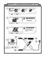
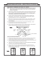
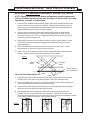
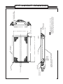
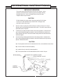
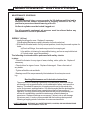
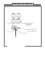
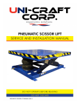
Part # 42448
Pneumatic Scissor Lift
Installation & Service Manual
Model #
Serial #
CONTENTS
G:\shared\Ed..DoNotRemove\StdManuals\ScissorLifts\PneumaticScissLift12-02
Responsibilities of Owners and Users
Page
1
Warnings
2
Safety Labels - Scissor Lift
3
Installation Instructions
4
Installation Instructions - Pit Mounted
5
Pit Layout Drawing
6
Operating Instructions
7
General Information
8
Maintenance Instructions
9
Pneumatic Schematic
11
Trouble Shooting
12
RESPONSIBILITIES OF OWNERS & USERS
Inspection and Maintenance: The lift shall be inspected and maintained in proper working
order in accordance with this manual and safe operating practices.
Removal From Service: Any lift not in safe operating condition shall be removed from
service until it is repaired to the original manufacturer’s standards.
Repairs: All repairs shall be made by authorized personnel in conformance with the
manufacturer’s instructions.
Operators: Only trained and authorized personnel shall be permitted to operate the lift. They
must understand to be alert to safety hazards during all operations.
Before Operation: Before using the lift, the operator shall have:
1. Read and understood the manufacturer’s operating instructions and safety
rules and been trained by a qualified person.
2. Inspected the lift for proper operation and condition. Any suspect item shall
be carefully examined and a determination made by a qualified person as to
whether it constitutes a safety hazard. All unsafe items shall be corrected
before further use of the lift.
During Operation: The lift shall be used only in accordance with its intended use and within
the manufacturer’s limitations and safety rules:
1. Do not overload the lift. Please note that the lift has a capacity tag attached
to it. Do not remove the tag. Be sure that no operator ever exceeds the
capacities shown on the tag or they may cause damage to the lift or injure
personnel.
2. Insure that all safety devices are operational and in place.
3. Insure that all personnel near operating lifts understand to stand back from
operating lifts so that no body parts can be pinched by the mechanism or
platform and any items that may fall off the lift will not strike them.
Modifications or Alterations: Modifications or alterations of industrial scissor lifts shall be
made in conformance with all applicable provisions of scissor lift manufacturer’s proposed
ANSI standards and shall be at least as safe as the equipment was before modification.
These changes shall also satisfy recommendations of the original equipment manufacturer
for the particular application of the lift.
1
WARNINGS
WARNING!!!
NO RIDERS!!!
WARNING!!!
To avoid personal injury, never go under the lift platform until the load is removed and
the scissor mechanism is securely blocked in the UP position to prevent accidental
lowering of the lift.
WARNING!!!
To avoid personal injury, stand clear of scissor leg mechanism while lift is in motion.
WARNING!!!
Where it is desired to raise the base of the lift to achieve a greater collapsed height,
the footprint of the base frame must be fully supported. Failure to do so will damage
the lift. This lift was designed to be a floor mount.
WARNING!!!
DO NOT install lifts in pits unless they have bevel toe guards or other approved toe
protection. A shear point can exist causing serious toe injury or severance.
Safety Maintenance Bar Procedure
WARNING!!!
ALWAYS use the safety bars for any service or maintenance. NEVER go under or
reach under the lift unless both safety bars are securely in place and the power to
the unit has been disconnected to prevent others from operating the lift. NEVER
use the safety bars with a load on the platform.
CAUTION
Never use the lift unless the safety bars are properly stored or damage may occur to
the equipment.
1. Remove the safety bars from their storage position.
2. Raise the lift to full travel, and place the safety bar. Make sure the safety bar
is in place.
3. Once BOTH safety bars are in place, slowly lower the lift until the safety bars
rest against the end of the baseframe. Visually inspect both safety
bars to insure they are secure.
4. To disengage the safety bars raise the lift to move the safety bars and make
sure lift operates correctly. Store the safety bars in the original position.
SAFETY WARNING: REPLACE ALL SAFETY DEVICES, GUARDS, AND GUARDING PRIOR
TO EQUIPMENT START UP.
2
SAFETY LABELS-SCISSOR LIFT
1
SAFETY LABELS
DANGER
To avoid bodily injury,
read all instructions
before operating or
servicing lift.
Do not put
hands or
feet under
top.
Do not work
under lift
without
maintenance
device.
Do not
stand, sit
or ride on
lift.
#113611 - A-4 (6 7/8 x 1 1/4) or B-4 (17 x 2)
Placed on the side edges of the lift table platform to warn personnel to read operating instructions before using lift
table, and to warn of possible bodily injury hazards.
WARNING
2
Do not stand,
sit or ride on lift
#113609 - A-1 (6 7/8 x 1 1/4 ) or B-1 ( 8” x 2)
Placed on the top surface of the lift table platform to warn personnel against riding on scissor lifts that are not
designed for such use.
DANGER
3
1234567
1234567
1234567
1234567
Do no work under lift
without maintenance
device
#113608 - A-3 (6 7/8 x 1 1/4) or B-3 (8 x 2)
Placed on the base frame adjacent to each maintenance device to warn service personnel to engage maintenance
device before working on, and particularly under, lift table.
4
12345678901
12345678901
12345678901
DANGER
To avoid bodily injury,
stand clear while
lift table is moving
#113610 - A-5 (6 7/8 x 1 1/4), B-5 (8 x 2), A-6 (2 x 1 /12)
Place on or near the control station where up/down controls
are located to warn personnel to stand clear while lift table
is in operation. Location can vary depending on type of
control station used.
3
INSTALLATION INSTRUCTIONS
Anchored Pneumatic Scissor Lift Tables
NOTE: Check your local codes before permanently installing pneumatic scissor lift
tables, as the process may be subject to local codes, rules and regulations,
permits, or inspections.
1. Scissor lifts are shipped on either skids or pallets. With slings placed around the base
frame or lift bottom, remove the lift from the skid. Be careful not to damage any of the
frame structure. If equipped with lifting tabs (tandem lifts or pit mounted lifts) attach a
chain spreader and raise the lift from a center position.
2. Level the scissor lift and place solid shims under the frame base as detailed in the
drawing below. Grout as required. If shimming and grout will not be used, the floor
must be level within 1/8 in. over 5 ft. of length and width.
3. Where anchor clips have been provided, the bolt fit is close to restrict shifting. Careful
location of the anchor bolts is required with special consideration being given to the
frame and platform.
4. The control pedestal is connected to the lift via an air hose at the factory. Locate
the pedestal at a convenient location and lag to the floor.
5 . Instruct user(s) in the proper operation of the lift, safety precautions, and equipment
capacity. Supply maintenance personnel with this service manual.
Figure 1
STABLE
ENDS
MOVABLE
ENDS
GROUT UNDER
SIDE CHANNELS
SHIM
INSTALLATION OF ANCHOR BOLTS
SHIMS
1. Position lift according to above instructions. Drill holes in concrete the same diameter
as anchor bolts, using anchor clip holes as guides. Drill holes sufficiently deep.
2. With nut and washer on anchor bolts, drive anchor bolts into holes so that a minimum of
six to seven threads are below the top of the anchor clips.
3. Tighten the nuts while making sure enough force is used to spread anchor bolt wedges.
Use three or four turns past finger-tightening as a guide.
4. After the scissor lift has been aligned, leveled and shimmed, and all anchor bolts
installed, pour 1 in. of grout under the entire base frame. Tighten nuts or anchor bolts
after the grout has set and cured.
1.
Figure 2
2.
3.
4
INSTALLATION INSTRUCTIONS
Anchored Pit Mounted Pneumatic Scissor Lift Tables
NOTE: Check your local codes before permanently installing pneumatic
scissor lift tables, as the process may be subject to local codes, rules and
regulations, permits, or inspections.
1. Scissor lifts are shipped on either skids or pallets. With slings placed around the base
frame or lift bottom, remove the lift from the skid. Be careful not to damage any of the
frame structure. If equipped with lifting tabs (tandem lifts or pit mounted lifts) attach a
chain spreader and raise the lift from a center position.
2. Level the scissor lift and place solid shims under the frame base as detailed in the
drawing below. Grout as required. If shimming and grout will not be used, the floor
must be level within 1/8 in. over 5 ft. of length and width. Removal of the lift top may be
required to access the anchor clips.
3. Where anchor clips have been provided, the bolt fit is close to restrict shifting. Careful
location of the anchor bolts is required with special consideration being given to the
frame and platform.
4. The control pedestal is connected to the lift via an air hose at the factory. Locate
the pedestal at a convenient location and lag to the floor.
5 . Instruct user(s) in the proper operation of the lift, safety precautions, and equipment
capacity. Supply maintenance personnel with this service manual.
Figure 1
STABLE
ENDS
MOVABLE
ENDS
GROUT UNDER
SIDE CHANNELS
INSTALLATION OF ANCHOR BOLTS
SHIM
SHIMS
1. Position lift according to above instructions. Drill holes in concrete the same diameter
as anchor bolts, using anchor clip holes as guides. Drill holes sufficiently deep.
2. With nut and washer on anchor bolts, drive anchor bolts into holes so that a minimum of
six to seven threads are below the top of the anchor clips.
3. Tighten the nuts while making sure enough force is used to spread anchor bolt wedges.
Use three or four turns past finger-tightening as a guide.
4. After the scissor lift has been aligned, leveled and shimmed, and all anchor bolts
installed, pour 1 in. of grout under the entire base frame. Tighten nuts or anchor bolts
after the grout has set and cured. Run pneumatic hose or electrical cord through the conduit
in the pit wall. Replace the platform. See Pit Layout Drawing.
3.
1.
2.
Figure 2
5
POWER SUPPLY CHASE
(BY OTHERS)
3 1/2 MAX FROM
FLOOR OF PIT
TO TOP OF PIPE
CHASE
PLATFORM LENGTH
CURB ANGLES
(BY OTHERS)
PLATFORM
PIT LENGTH = PLATFORM LENGTH + 1 1/2
1 3/4 DEEP X 3 1/2 WIDE RECESS FOR CABLES
(INTERNAL POWER UNIT), OR HOSES (REMOTE
POWER UNIT) BY OTHERS
CURB ANGLES
(BY OTHERS)
PIT CENTER LINE
PLATFORM
(REF)
LOWERED
HEIGHT
PIT WIDTH = PLATFORM WIDTH +1 1/2
PIT DEPTH
(Lift Lowered height plus
1/2” for shims or grout)
MINIMUM CLEARANCE
PLATFORM WIDTH
NOTES:
1.) ALL PIT WORK BY OTHERS, INCL. CONDUIT, PIPING,
CURB ANGLES, ETC.
2.) RUN 3” DIA. PVC WITH LONG RADIUS SWEEP ELBOWS
TO PROVIDE PIPE CHASE FOR HOSE OR CABLES, RUN
FROM PIT TO POWER UNIT OR CONTROL LOCATION
3/4
3/4
Sump and / or drain
(If required by others)
PIT LAYOUT DRAWING
6
OPERATING INSTRUCTIONS
METHOD OF OPERATION
The control valve controls the flow of air to the air actuator. As the
actuator is pressurized, the scissor legs are forced apart causing
the table top to rise. As air is released from the bag, the legs
collapse and the top is lowered.
CAUTION!
Do Not maintain the control valve in the open position if the lift does
not move or it has reached its up or down limits. Damage to the
pneumatic system may result.
1.
Connect clean, dry shop air (minimum 80 psi, maximum 100 psi, 15 cfm) to
the open port on the pedestal mounted control valve. Test all air connections for
leaks and repair as required.
2.
To lift the unit, activate the hand control valve to the up position. Hold the valve
open until the desired height is reached or until the lift reaches it's positive up
stops. Release the valve. The lift will remain at this position until the hand valve
is activated again.
3.
Lower the lift by activating the hand valve to the down position. Hold the valve
open until the desired height is reached or until the lift reaches it's fully lowered
position. Release the valve.
CAUTION!
A) Do not operate the lift until it is fastened to the floor, see Installation Instructions.
B) Do not exceed the rated load capacity.
C) Load the lift only in the fully lowered position.
D) Do not place hands or feet underneath the skirts or table / tilt tops.
AIR IN
FLOW CONTROL LEVER
FLOW CONTROL VALVE
CONTROL
PEDESTAL
7
GENERAL INFORMATION
GENERAL INFORMATION
End and Side Loading - Reduce the lift end and side placing capacities by 2% for every inch added to the
standard minimum platform length or width. Reduce the lift end or side loading capacities by 33% if loads
are going to be rolled onto the platform when the lift is other than fully lowered.
Technical - Speed and capacity on an air spring actuated lift are affected by plant air pressure (PSI) and
standard cubic feet/minute (SCFM). SCFM is a function of compressor capacity. Plant air pressure is
normally 100 PSI while standard cubic feet/minute should have 15 SCFM capabilities (approx. 4 HP air
compressor minimum). Increasing SCFM will increase lift speed. Increasing PSI will increase capacity and/
or lift speed.
Know the capacity of your equipment. Center your load on the lift at all times. The equipment design is
for balanced centered loads. If field additions are made to the lift, reduce the capacity of the unit by the
equipment added.
8
MAINTENANCE INSTRUCTIONS
GENERAL MAINTENANCE NOTES
1.
Always remember that this is a piece of machinery with large moving parts that can seriously
hurt you. Read and understand this manual before attempting any maintenance on the lifts.
2.
Always use safety maintenance bars when servicing or inspecting any pneumatic lift. After
the safety bars are in place, remove the system air pressure by using the control lever. Never
reach under a lift unless it is properly shored or blocked.
3.
When using the safety supports, adhere to the following rules:
A. Be sure there is no load on the platform.
B. Be sure the safety support is properly engaged.
C. Hold the down pedal an extra 10 seconds when lowering onto the safety
support to be sure that all the weight of the lift is on the support.
D. Disconnect and tag the unit to prevent accidental movement of the lift by
other personnel.
E. Spend as little time as possible under the lift.
4.
Use only replacement parts recommended by the manufacturer.
5.
Do not let the equipment stay in disrepair; fix little problems while they are little
problems or some of them may get very severe very quickly.
6.
Inspect the equipment on a regular schedule, preferably monthly.
7.
Never work on the air systems unless the unit is fully lowered or properly sitting on a
safety support.
8.
Never apply a load to the equipment unless the base is continuously supported.
9.
Oversize platforms can have a considerable overhang of the platform clevis
pins, and as the platform is hinged on one end and free at the other, this may
create a teeter-totter. In addition to the normal end load derating of 2% per
additional platform inch, care should be taken not to overload the clevis end of
the platform to the extent that the opposite (roller) end of the platform is able to tilt
upward, possibly spilling the load.
10.
Never expect to hold a leg assembly by simply lifting one end of a platform:
A. The roller end of most lifts is not gibbed or captured in any way, so lifting on the roller
end simply tilts the platform.
B. Even if you raise the clevis end of the platform, if the base frame is not firmly lagged to
the ground or held down by some other means, the legs will come up with the platform in a
spongy and unpredictable manner and could cause personal injury.
C. The only safe way to hold a lift’s legs open other than the factory designed safety
support, is to block between the clevis end of the platform and the base frame.
The routine maintenance of this equipment is minor and consists of periodic checks.
The equipment has been designed to safely provide many years of service if properly used and
maintained.
SAFETY WARNING: REPLACE ALL SAFETY DEVICES, GUARDS, AND GUARDING PRIOR
TO EQUIPMENT START UP.
9
MAINTENANCE INSTRUCTIONS
MAINTENANCE SCHEDULE:
WARNING:
To avoid personal injury, never go under the lift platform until the load is
removed and the scissor mechanism is securely blocked in the "up"
position to prevent accidental lowering of the lift.
Air flow to cylinder must be locked / tagged out.
For all pneumatic equipment, air pressure must be relieved before any
maintenance or service is performed.
WEEKLY (40 hrs.)
- Inspect bushings for wear. Replace if necessary.
(See Bushing Maintenance and Lubrication Instructions below.)
- With the lift unloaded and in it's fully raised position, check the pneumatic system for
leaks.
a) Check all fittings, lines and components for escaping air.
b) In addition to listening for an audible hissing, perform a soap bubble test.
c) If a leak exists, repair immediately.
The following checks should be performed with safety chocks
in place.
- Check Air Actuator for any signs of wear, chafing, nicks, splits, etc. Replace if
necessary.
- Check rollers for signs of wear. Replace if damaged. Clear roller track of
any debris.
- Tighten all visible nuts and bolts.
- Bearings on all lifts are permanently lubricated and do not require servicing.
Bushing Maintenance and Lubrication Instructions
The service life of a bushing is generally not predictable, since their failure
will develop only as gradual wear, not as catastrophic failure, such as with a
bearing. The need for inspection is largely proportional to the actual duty
cycle, environment, and application. It is recommended that the bushings be
inspected for wear at least once a week during the first few months of
operation. It is likely that such frequent attention will prove unnecessary, but
will result in establishing a realistic maintenance schedule based on
experience. Replace bushings as necessary. Failure to do so will damage
the scissor arms. It is also recommended that the bushings be inspected
following a lengthy period of shutdown in severe environments.
SAFETY WARNING: REPLACE ALL SAFETY DEVICES, GUARDS, AND GUARDING PRIOR
TO EQUIPMENT START UP.
10
PNEUMATIC SCHEMATIC
PNEUMATIC CIRCUIT
(Hand Valve)
PLUG
AIR ACTUATOR QUANTITY
DETERMINED BY
LOAD CAPACITY
HAND VALVE (SHOWN)
OR
OPTIONAL FOOT PEDAL
PLUG
MUFFLER
AIR
IN
11
TROUBLE SHOOTING
WARNING:
To avoid personal injury, never go under the lift platform until the load is
removed and the scissor mechanism is securely blocked in the "up"
position to prevent accidental lowering of the lift.
Air flow to cylinder must be locked / tagged out.
For all pneumatic equipment, air pressure must be relieved before any
maintenance or service is performed.
TROUBLE SHOOTING MAINTENANCE:
- LIFT MOVING SLOWLY OR NOT AT ALL -
1.
Check for obstructions.
2.
Check for incoming air supply.
3.
Check circuit for air leaks -- loose connection,
damaged hose, etc. Listen for air escaping.
4.
Is lift overloaded? Check capacity.
5.
Check hand control valve and regulator for
sticking or jamming -- repair or replace.
SAFETY WARNING: REPLACE ALL SAFETY DEVICES, GUARDS, AND GUARDING PRIOR
TO EQUIPMENT START UP.
12