1
Thermoregulation Systems S E R V I C E M A N U A L Catalog No.FDT-200-000 Rev: C R e v i s e d December 2 0 1 3 For CritiCool machines with 00 Conformity according to the Council Directive 93/42/EEC concerning Medical Devices as amended by 2007/47/EC. Manufacturer’s Name : MTRE Advanced Technologies Ltd. 4 Hayarden Street, Yavne, 81228 P.O. Box 102, Rehovot, 76100, Israel Tel.: +972-8-9323333 Fax: +972-8-9328510 European Representative : Charter-Kontron Limited Unit 18 Avant Business Centre 21 Denbigh Road Milton Keynes MK1 1DT England Tel.: 01908 646070 Fax: 01908 646030 US Representative: Mennen Medical Corp. 290 Andrews Road Feasterville-Trevose, PA 19053-3480 Phone 215 259-1020 Fax 215 357-2010 C a t a l o g N o . FDT-200-000 Rev C Revised December 2013 (For 100-OPT99) Copyright © MTRE Advanced Technologies Ltd. 2013 All RIGHTS RESERVED Registered trademarks are the intellectual property of their respective holders. Thermoregulation® Service Manual Copyright 2013 by MTRE All rights reserved. No part of this manual may be reproduced or copied in any form by any graphic, electronic or mechanical means – including photocopying, scanning, typing or information retrieval systems – without advanced written permission from MTRE. U.S. Patent No. 6,500,200 BI Disclaimer MTRE is not responsible for any consequential or incidental damages or expenses of any kind, impairment of or damage to other goods or to any third party resulting from loss of use of the system caused by or due to the following: a. Installed, operated, maintained contrary to MTRE’s instructions, notes or warnings under this manual. b. Misuse, unauthorized use, negligence, accident, (including fire, water, explosion, smoke, vandalism, etc.) c. Ignoring any of the warnings, precautions and safety measures indicated in this manual. d. Replace, repair or alter not by MTRE’s authorized personnel. e. Anyone other than MTRE’s authorized and certified personnel removes, casing and/or attempts to make or makes any internal changes, removals, attachments or additions to the Thermoregulation System or components thereof; f. The power supplied to the System or any part thereof differs from the rated value, or any external device attached by user creates conditions exceeding the tolerance of the System; or g. The use of accessories and other parts or equipment made by other manufacturers, whether or not warranted by such manufacturers, which have been attached or connected to the System after installation, unless such accessories and other parts have been supplied and attached or installed by the MTRE. h. Using the system in a contrary manner than indicated in this manual, or using the system for any purpose other than indicated in the manual. i. Failure to replace the Garment in each procedure while operating the system. Note that all Garments are one-use disposable materials and should not be reused. j. Force Majeure In no event shall MTRE be liable for loss of use, loss of profits, or other collateral, special or consequential damages. ii MTRE Advanced Technologies Ltd. Thermoregulation® Service Manual Use of Manual The MTRE Thermoregulation system described in this manual has been designed to meet international safety and performance standards. Only qualified personnel may service the system, and these field engineers must first have a full understanding of the proper operation of the system. The purpose of this manual is to help qualified personnel understand and service the system. It is important that you read this manual and familiarize yourself thoroughly with its contents before you attempt to service the system. If you do not understand any part of this manual, or if anything is unclear or ambiguous in any way, please contact your MTRE representative for further clarification. The information provided in this manual is not intended to replace regular medical training procedures. Field Repairs Statement Repair of MTRE. Equipment in the field will be performed by service engineers, authorized by MTRE Repair will be performed on a board level only. The list of replaceable component and boards is available in the spare part list.(Appendix B) System testing will be performed using the test form available in the Service manual. Training and Qualification MTREor it's authorized distributer will provide training for technicians and sales personal as per the Intended use of the device or system. The scope of the training is part of the agreement between MTRE or it's authorized distributer and/or the end user. Servicing of MTRE equipment is allowed only to persons that were trained and qualified to service the equipment efficiently and safely. Warning!!! No modification of this equipment is allowed. Software update must be performed by service engineer authorized by MTRE. MTRE Advanced Technologies Ltd. iii Thermoregulation® Service Manual iv MTRE Advanced Technologies Ltd. Thermoregulation® Service Manual TABLE OF CONTENTS Chapter 1: About This Manual Applicable Systems ................................................................................................................................ 1-1 Garments ............................................................................................................................................... 1-1 Essential Performance ............................................................................................................................ 1-1 Chapter 2: Warnings and Precautions Definitions ............................................................................................................................................. 2-1 Intended Use ......................................................................................................................................... 2-1 Warnings ............................................................................................................................................... 2-1 Precautions ............................................................................................................................................. 2-2 Labels ..................................................................................................................................................... 2-4 Thermoregulation Device Labels ........................................................................................................ 2-4 ............................................................................................................................................................. 2-4 Chapter 3: System Description General Description ............................................................................................................................... 3-1 Thermoregulation Device .................................................................................................................... 3-1 External Features .................................................................................................................................... 3-2 Front View ........................................................................................................................................... 3-2 Side View ............................................................................................................................................ 3-3 Rear Panel ............................................................................................................................................ 3-4 Accessories ......................................................................................................................................... 3-4 Chapter 4: Installation Pre-installation Requirements ................................................................................................................ 4-1 Space and Environmental Requirements ............................................................................................. 4-1 Electrical Requirements ....................................................................................................................... 4-1 Unpacking and Inspection ................................................................................................................... 4-1 Assembling the Handle ........................................................................................................................ 4-1 Accessory Kits ..................................................................................................................................... 4-3 Moving the Unit ..................................................................................................................................... 4-5 Preparation .......................................................................................................................................... 4-5 Locking and Unlocking the Trolley Wheels ....................................................................................... 4-6 Storage Conditions and Transport .......................................................................................................... 4-6 Storage Environment ........................................................................................................................... 4-6 Chapter 5: Panels and Covers Introduction ........................................................................................................................................... 5-1 Removal of the Trolley ......................................................................................................................... 5-8 MTRE Advanced Technologies Ltd. iv Thermoregulation® Service Manual Chapter 6: Electrical System Introduction .......................................................................................................................................... 6-1 Release of PCB Spacer Supports ........................................................................................................... 6-2 Slide Lock Connector ............................................................................................................................ 6-2 Power Supply Assembly ........................................................................................................................ 6-2 Controller Board .................................................................................................................................... 6-4 Controller Board Fuses ....................................................................................................................... 6-7 Removal of Controller Board ............................................................................................................. 6-7 TEC Control (Thermo-Electric Components) Board ............................................................................ 6-8 Human Sensors (HS) Board ................................................................................................................ 6-12 MMI (Man-Machine Interface) ........................................................................................................... 6-15 FP Board .............................................................................................................................................. 6-16 HCU (Heating Cooling Unit) .............................................................................................................. 6-18 Z Heat Exchanger ............................................................................................................................. 6-19 Thermal Exchange Components (Peltier) ......................................................................................... 6-20 Heat Sink .......................................................................................................................................... 6-20 Fan .................................................................................................................................................... 6-20 Pump ................................................................................................................................................... 6-22 Solenoid Bypass Valve ........................................................................................................................ 6-22 Thermistors .......................................................................................................................................... 6-23 Water-out and Thermostat Thermistor Replacement ........................................................................ 6-23 Water-in Thermistor Replacement .................................................................................................... 6-24 Float .................................................................................................................................................... 6-25 Chapter 7: Hydraulic System Introduction .......................................................................................................................................... 7-1 Water Tank Assembly ........................................................................................................................... 7-3 Water Tank Top Cover Assembly ...................................................................................................... 7-4 Filter ..................................................................................................................................................... 7-5 ............................................................................................................................................................... 7-5 Replacing the Filter ............................................................................................................................. 7-5 Removing the Filter ............................................................................................................................ 7-5 Installing the New Filter ..................................................................................................................... 7-6 Pump ..................................................................................................................................................... 7-7 Removing the Pump ............................................................................................................................ 7-7 Pump Block Diagram .......................................................................................................................... 7-9 Solenoid Bypass Valve .......................................................................................................................... 7-9 Water-In and Water-Out Connectors .................................................................................................. 7-10 Chapter 8: Software Overview ............................................................................................................................................... Self-Test ............................................................................................................................................... Safety Algorithm ................................................................................................................................... Halt Conditions ..................................................................................................................................... Technician Mode Error Messages ......................................................................................................... Explanation of Error Messages ........................................................................................................... v 8-1 8-1 8-1 8-2 8-3 8-3 MTRE Advanced Technologies Ltd. Thermoregulation® Service Manual Chapter 9: Periodic Maintenance Overview of the Periodic Maintenance Procedures ............................................................................... 9-1 Removing the Cover .............................................................................................................................. 9-2 Replacing the Water Filter ..................................................................................................................... 9-2 Activating the CritiCool Machine .......................................................................................................... 9-2 Human Sensors Verification .................................................................................................................. 9-2 Water Temperature Sensors Verification ............................................................................................... 9-4 Thermostat Verification ......................................................................................................................... 9-6 Pressure Verification ............................................................................................................................. 9-8 TEC Current Test ................................................................................................................................... 9-9 Check for Water Leakage ..................................................................................................................... 9-11 Self-test ............................................................................................................................................... 9-11 Replacing Controller Board Fuses ..................................................................................................... 9-11 Chapter 10: Troubleshooting Halt Messages ...................................................................................................................................... 10-1 Text Messages ...................................................................................................................................... 10-3 Chapter 11: Special Equipment and Tools Calibration Toolset: Verification and Calibration Units ...................................................................... 11-1 MTRE Temperature Calibration Unit P/N: 017-00184 ....................................................................... 11-2 MTRE Temperature Calibration Unit - Controls .............................................................................. 11-2 Analog Flow and Pressure Calibration Unit P/N 017-00190 ............................................................... 11-4 Digital Pressure Gauge P/N 017-00290 ............................................................................................ 11-4 TEC Current Verification Unit ............................................................................................................ 11-6 Calibration Cables ................................................................................................................................ 11-7 Core Calibration Cable ...................................................................................................................... 11-7 Surface Calibration Cable .................................................................................................................. 11-7 Standard Tools ..................................................................................................................................... 11-8 Calibration Test for the MTRE Temperature Calibration Unit ............................................................ 11-8 Thermostat Verification Tool ............................................................................................................... 11-9 PCB Extraction Tool ............................................................................................................................ 11-9 Chapter 12: Specifications Appendix A: Technician Mode Technician Mode ................................................................................................................................... A-1 Technician Mode Screen .................................................................................................................... A-1 Technician Mode Screen—Details ..................................................................................................... A-2 Entering Technician Mode ................................................................................................................... A-4 Appendix B: Spare Parts List Disclaimer ............................................................................................................................................. B-1 CritiCool™ – Cooling Control Unit ..................................................................................................... B-1 CritiCool™ – Spare Parts List ........................................................................................................... B-2 MTRE Advanced Technologies Ltd. vi Thermoregulation® Service Manual Allon 2001™ – Warming Control Unit, Version-05 .......................................................................... B-17 Allon 2001™ – Spare Parts List For, Version-05 ............................................................................ B-17 Upgrade Package for Allon 2001™ Warming Control Unit ........................................................... B-17 Appendix C: Service Form Appendix D: Periodic Maintenance For Stimlator: TP-400 FOGG .............................................................................................................. D-1 For Stimulator MTRE Temperature Calibration Unit .......................................................................... D-5 Appendix E: Downloading Updated CritiCool Software vii MTRE Advanced Technologies Ltd. CHAPTER 1: ABOUT THIS MANUAL Applicable Systems This Service Manual covers all Normothermia management and Cooling Therapy systems produced by MTRE Advance Technology Ltd. To avoid confusion, all systems will be referred to in this manual as the Thermoregulation System. Information (component descriptions or procedures) specific to any particular system will be noted within the manual in the relevant section. Garments The Thermoregulation System is designed to function with both the ThermoWrap and the CureWrap systems. Both ThermoWrap and CureWrap will be referred to in this manual as the Garment. Information specific to any one of these Garments will be noted within the manual in the relevant section. Essential Performance The following functions are considered by the manufacturer as essential: • Water temperature control • Unexpected core temperature alarm WARNING!!!The system will HALT if any of these elements of the control mechanism fail. MTRE Advanced Technologies Ltd. 1-1 About This Manual 1-2 Thermoregulation® Service Manual MTRE Advanced Technologies Ltd. CHAPTER 2: WARNINGS AND PRECAUTIONS Definitions WARNING!!!Indicates a condition that may endanger the patient or the system operator. CAUTION! Indicates a condition that may damage the equipment. Note: Indicates ways in which the system’s operation can be made more efficient. Intended Use The Thermoregulation System is designed to regulate body temperature as determined by the physician. Warnings 1. The physician must be notified if the patient's temperature does not respond properly, does not reach the prescribed temperature, or if there is any change in the prescribed temperature range. Failure to inform the physician may result in injury to the patient. 2. The patient should be constantly attended by a physician. 3. Mishandling of the temperature regulation equipment can be potentially harmful to the patient. 4. Do not plug wet PL plugs of the human sensors into the sensor sockets of the Thermoregulation device. 5. The user should verify that no fluids are present at the skin/Garment interface during the operation. Failure to do so can cause lesions on the patient's skin. Following the procedure, a pattern resembling the Garment may appear for a short period of time on the patient's skin. 6. In operations that usually extend over two hours, pressure sores may appear or develop when soft tissue is compressed between a bony prominence and external surface. The use of the MTRE Advanced Technologies Ltd. 2-1 Warnings and Precautions Thermoregulation® Service Manual Thermoregulation system does not prevent this occurrence. It is therefore recommended to use pressure sores protective means between the operating table and the Garment. 7. Before initiating maintenance procedures as described in Chapter 9, disconnect the power cable from the power source. 8. The default setting is intended to maintain normothermia. However, the system provides the physician with the option of selecting a body temperature in the range of 30°C to 40°C (86°F to 104°F). 9. Do not lift or move the patient by means of the Garment. This may cause tearing and water leakage. 10. Use reusable core sensors or disposable sensor adapters supplied by MTRE or YSI series 400 compatible sensors. 11. The technical principles, clinical applications, and risks associated with circulatory support must be thoroughly understood before using this product. Read the entire manual before attempting to activate the system. Completion of the training program prior to using the Thermoregulation system is mandatory. 12. Repair, and servicing of the Thermoregulation System should be performed only by MTRE Advanced Technologies LTD or authorized agents of MTRE Advanced Technologies LTD. Precautions Follow the warning notes listed in the various sections of this manual. Only trained personnel, familiar with all system operating procedures and certified only by MTRE Advanced Technologies Ltd or authorized agents of MTRE Advanced Technologies Ltd, are allowed to use the Thermoregulation System. All hospital personnel using the Thermoregulation system must complete the Thermoregulation training program. The repair, and servicing of the Thermoregulation device should be performed only by qualified medical equipment service technicians, certified by MTRE Advanced Technologies Ltd or authorized agents of MTRE Advanced Technologies Ltd. If moisture or leaks are discovered in the connecting hose and/or Garment, turn off the Thermoregulation device, disconnect the power cable from its power source, and correct the problem before proceeding. The desired set-point temperature should be fixed only as prescribed by and under the order of a physician. If the Thermoregulation device sounds an alarm and / or presents a display other than the standard MTRE display, the operator should proceed according to the display message and / or the troubleshooting instructions (see Chapter 10: Troubleshooting). Avoid folds in the Garment—these may obstruct water flow. 2-2 MTRE Advanced Technologies Ltd. Thermoregulation® Service Manual Do not block the Thermoregulation device ventilation grills. Air must be able to flow freely in and out in order to the device cool. Do not use de-ionized or distilled water. Use tap water only. When X-ray imaging is performed on a patient wearing a Garment, shadows from the Garment may appear on the X-ray film. Avoid inserting any sharp object between the patient and the Garment. WARNING!!!Improper use of the Thermoregulation systems, may lead to skin burns, electrical hazards, and several changes in body temperature. CAUTION! The technical principles, clinical applications, and risks associated with circulatory support must be thoroughly understood before using this product. Read the entire manual before attempting to activate the system. Completion of the training program prior to using the Thermoregulation system is mandatory WARNING!!!U.S. Federal law restricts this device to sale by or on the order of a physician. MTRE Advanced Technologies Ltd. 2-3 Warnings and Precautions Thermoregulation® Service Manual Labels Thermoregulation Device Labels Figure 2-1: Label Placement for the CritiCool Thermoregulation Device 2-4 MTRE Advanced Technologies Ltd. Thermoregulation® Service Manual Figure 2-2: Label Placement for the Allon Thermoregulation Device MTRE Advanced Technologies Ltd. 2-5 Thermoregulation® Service Manual Warnings and Precautions Table 2-1: Key for Label Symbols Symbol Description Location of core sensor socket Location of surface sensor socket AC Voltage Fuse The CE mark of conformity indicates that the product has received the European approval for MDD 93/42/EEC. Equipment not suitable in the presence of flammable anesthetic mixture with air or with oxygen or nitrous oxide. See User Manual Type BT equipment Date of manufacture The CSA symbol indicates that the product has received the approval of the Canadian Standards Association. xx-yyyy Machine Version - Machine serial number Water-in connector indicator Water-out connector indicator No Pushing 2-6 MTRE Advanced Technologies Ltd. Thermoregulation® Service Manual System Description CHAPTER 3: SYSTEM DESCRIPTION General Description MTRE's Thermoregulation system induces, maintains, and reverses hypothermia in an effective and precise manner. The desired temperature is preset by the physician with a possible range of target temperature from Mild Hypothermia to Normothermia. The system is composed of two elements, the Thermoregulation device and the Garment. The Thermoregulation device functions as a control unit and a cooling/heating pump which circulates water. The control unit constantly monitors the patients' core temperature through specific sensors, and, using its on-board body temperature control algorithm, delivers the optimum water temperature to reach the desired set point temperature. The cooling/heating pump brings the water to the required temperature and the pump circulates it through the specially designed Garment. The Garment is a flexible 3D single piece design, through which the water circulates. It is designed to be in close contact with a large contact area of the body, thus allowing optimization of energy transfer. . The MTRE garment is proprietary to MTRE and this is the only garment authorized to be used with the Thermoregulation Device. Thermoregulation Device The Thermoregulation device has a microprocessor that controls the water temperature to the Garment worn by the patient. The decision as to the correct water temperature is based on the desired set point temperature and the actual measured patient temperature (core and surface). Water pressure in the Garment is regulated by timed pauses of the flow during clinical operation. The Thermoregulation device is equipped with a handle for easy transport. CAUTION!Never place the Thermoregulation device on its rear or side. MTRE Advanced Technologies Ltd. 3-1 Thermoregulation® Service Manual System Description External Features Front View Figure 3-1: Front View 3-2 MTRE Advanced Technologies Ltd. Thermoregulation® Service Manual Side View Figure 3-2: Side View MTRE Advanced Technologies Ltd. 3-3 Thermoregulation® Service Manual System Description Rear Panel Figure 3-3: Rear View Accessories To operate the Thermoregulation system, the following accessories are needed: 1. Human Temperature Sensors • Reusable Sensors There are three color-coded sensors: Core (gray), Surface (green), and Infant Core (gray). Both core and surface sensors must be plugged into the device. The core sensor must be inserted into the patient's body and the surface sensor must be attached to the patient's skin for the device to function properly. • Disposable Sensors Disposable sensors are attached to two color-coded adapters: gray (Core) and green (Surface). The core sensor must be inserted into the patient's body and the surface sensor must be attached to the patient's skin for the device to function properly. Sensors and adapters are guaranteed for one year. 3-4 MTRE Advanced Technologies Ltd. Thermoregulation® Service Manual WARNING!!!Use reusable core sensors or disposable sensor adapters supplied by MTRE or YSI series 400 compatible sensors. Use reusable surface sensors or disposable surface sensor adaptors supplied by MTRE only. • Reusable Core Sensor (Part No. 014-00020): The core sensor (gray) measures core body temperature when inserted into the patient’s body. The PL plug of the sensor cable is plugged into the gray core sensor socket at the front of the Thermoregulation device. The other end is inserted into the patient and measures core body temperature. • Disposable Core Sensor Adapter (Part No. 014-00028): The disposable sensor is attached to the core sensor adapter (gray). The PL plug of the adapter is plugged into the gray core sensor socket at the front of the Thermoregulation Device. The sensor is inserted into the patient and measures core body temperature. • Reusable Infant Core Sensor (Part No. 014-00005): The infant core sensor (gray) measures infant core body temperature when inserted into the patient’s body. The PL plug of the sensor cable is plugged into the gray core sensor socket at the front of the Thermoregulation device. The other end is inserted into the patient and measures core body temperature. • Reusable Surface Sensor (Part No. 014-00021): The surface sensor (green) measures body surface temperature when attached to the patient's skin. The PL plug of the sensor cable is plugged into the green surface sensor socket at the front of the Thermoregulation device. The other end is attached with adhesives to the patient’s skin. • Disposable Surface Sensor Adapter (Part No. 014-00129): The disposable sensor is attached to the surface sensor adapter (green). The PL plug of the adapter is plugged into the green surface sensor socket at the front of the Thermoregulation device. The sensor is attached with adhesives to the patient’s skin and measures surface body temperature. Table 3-1: Sensors and Data Provider Input Specification Model No. Name Description 014-00020 Core Inner body temp. 014-00021 Surface Skin temp 014-00005 Core Infant Infant Inner body temp. MTRE Advanced Technologies Ltd. Accuracy ± 0.3°C Resolution Type ± 0.1°C Medical Grade Thermistor ± 0.3°C ± 0.1°C Medical Grade Thermistor ± 0.3°C ± 0.1°C Medical Grade Thermistor 3-5 System Description Thermoregulation® Service Manual 2. Detachable Electric Power Cable and Plug • Power cord (European Standard) (Part No. 014-00017) • Power Cord (USA Standard-Hospital Grade) (Part No. 014-00016) 3. .Connecting Tubes for CureWrap (Part No. 200-00147) Two flexible 2.5 m long, color-coded connecting tubes, connect a CureWrap with the Thermoregulation device to enable the flow of water between them. The tubes are supplied as a paired unit with two male Quick Coupling Connectors at the Thermoregulation device end and with three female Quick Coupling Connectors at the CureWrap end. 4. Connecting Tubes for ThermoWrap or CureWrap Garments (Part No. 200-00109) Two flexible 2.5m long connecting tubes connect the Garment with the Thermoregulation device to enable the flow of water between them. The tubes are supplied as a paired unit with two male Quick Coupling Connectors at the Thermoregulation device end and with two female Quick Coupling Connectors at the Garments end. 5. Male Connector for Draining Water Tank (Part No. 002-00069) Refer to Section "Draining the Water Tank" in Chapter 9. 6. Spare Water Filter (Part No. 200-00130) For annual filter replacement - packed in the accessory box 7. Handle • Allon Model (Part No. 007-00333) • CritiCool Model (Part No. 007-00365) 3-6 MTRE Advanced Technologies Ltd. CHAPTER 4: INSTALLATION Pre-installation Requirements Space and Environmental Requirements The Thermoregulation device is supplied on a trolley as a mobile unit for user convenience. Locate the Thermoregulation device not less than 5 cm (2") from other objects to avoid impairing its ventilation. The following dimensions should be considered when placing the Thermoregulation device: 260 mm W x 625 mm D x 940 mm H / (10.23"W x 24.6"D x 37"H) Electrical Requirements 230/120 VAC 500W CAUTION! Verify that the voltage switch is set for the local voltage. Unpacking and Inspection The Thermoregulation device has undergone full quality assurance testing before shipment and should be operational upon delivery. The device should be unpacked, installed and tested only by MTRE’s authorized personnel. No attempt should be made by the purchaser to unpack or assemble the device alone. Note: Report any container damage prior to opening the container, or any unit damage prior to unpacking, installation, or testing to your MTRE distributor. Assembling the Handle To assemble the handle: 1. Release the four thumb captive screws from the handle. MTRE Advanced Technologies Ltd. 4-1 Thermoregulation® Service Manual Installation 2. Slide the two ends of the handle into the holes in the top cover (pay attention to the direction of the curve in the handle) until the handle is inserted all the way in (see Figure 4-1). 3. Press in and screw the four thumb captive screws by hand (do not use force when screwing) to secure the handle and the top cover. Figure 4-1: Handle Assembly 4-2 MTRE Advanced Technologies Ltd. Thermoregulation® Service Manual Accessory Kits Note: Refer to User's Manual for the equipment list specific to the Thermoregulation model. The Thermoregulation system includes one of the following accessories kits: Allon 2001™ Accessory Kits Table 4-1: Acc. Kit for Adult with Reusable Temperature Sensors - 200-00400 QTY Description Part Number 1 Connector 1/4' with hose barb 002-00069 1 Adult Eso / Rectal Core Sensor 014-00020 1 SURF Sensor, YSI B-C, GREEN 014-00021 1 Accessories Box 015-00035 1 ThermoWrap Connecting Tube 200-00109 1 Filter Assembly 200-00130 1 Quick Reference Guide, English 014-00058 1 Label Set, Multilanguage 200-00091 Table 4-2: Acc. Kit for Adult with Interface Cables Only for Disposable Sensors - 200-00410 QTY Description Part Number 1 Connector 1/4' with hose barb 002-00069 1 Interface Cable for Disp. Core Sensor 014-00028 1 Interface Cable for Disp. SURF Sensor 014-00029 1 Accessories Box 015-00035 1 ThermoWrap Connecting Tube 200-00109 1 Filter Assy 200-00130 1 Quick Reference Guide, English 014-00058 1 Label Set, Multilanguage 200-00091 MTRE Advanced Technologies Ltd. 4-3 Thermoregulation® Service Manual Installation Table 4-3: Acc. Kit for Infant with Reusable Temperature Sensors - 200-00420 QTY Description Part Number 1 Connector 1/4' with hose barb 002-00069 1 Infant Eso / Rectal Core Sensor 014-00005 1 SURF Sensor, YSI B-C, GREEN 014-00021 1 Accessories Box 015-00035 1 ThermoWrap Connecting Tube 200-00109 1 Filter Assy 200-00130 1 Quick Reference Guide, English 014-00058 1 Label Set, Multilanguage 200-00091 CritiCool™ Accessory Kits Table 4-4: Acc. Kit for Adult with Reusable Temperature Sensors -200-00300 QTY Description Part Number: 1 Connector 1/4' with hose barb 002-00069 1 Adult Eso / Rectal Core Sensor 014-00020 1 SURF Sensor, YSI B-C, GREEN 014-00021 1 Accessories Box 015-00035 1 Filter Assy 200-00130 1 CureWrap Connecting Tubes 200-00147 1 Quick Reference Guide, English 014-00082 1 Label Set, Multilanguage 200-00142 Table 4-5: Acc. Kit for Infant with Reusable Temperature Sensors - 200-00320 QTY 1 4-4 Description Connector 1/4' with hose barb Part Number: 002-00069 MTRE Advanced Technologies Ltd. Thermoregulation® Service Manual Table 4-5: Acc. Kit for Infant with Reusable Temperature Sensors - 200-00320 1 Interface Cable for Disp. Core Sensor 014-00028 1 Interface Cable for Disp. SURF Sensor 014-00029 1 Accessories Box 015-00035 1 Filter Assy 200-00130 1 CureWrap Connecting Tubes 200-00147 1 Quick Reference Guide, English 014-00082 1 Label Set, Multilanguage 200-00142 Table 4-6: Acc. Kit for Infant with Interface Cables Only for Disposable Sensors - 200-00330 QTY Description Part Number: 1 Connector 1/4' with hose barb 002-00069 1 Interface Cable for Disp. Core Sensor 014-00028 1 Interface Cable for Disp. SURF Sensor 014-00029 1 Accessories Box 015-00035 1 ThermoWrap Connecting Tube 200-00109 1 Filter Assy 200-00130 1 Quick Reference Guide, English 014-00082 1 Label Set, Multilanguage 200-00142 Moving the Unit Preparation Prior to moving the unit: 1. Ensure that the Thermoregulation device is off by pressing the ON / OFF switch. 2. Ensure that all electrical connections are disconnected. MTRE Advanced Technologies Ltd. 4-5 Thermoregulation® Service Manual Installation Locking and Unlocking the Trolley Wheels The Thermoregulation device trolley has four wheels. The front wheels are fitted with a brake. The brake lever is located over the wheel. To lock, firmly depress the lever. To release, lift the lever. When the unit is stationary, the brakes must be in the locked position. Release the brakes only when transporting the unit. Storage Conditions and Transport Storage Environment Store the Thermoregulation device in a clean and dry area with: • An ambient temperature of -40°C to +70°C (-40°F to +158°F) • A relative humidity range of 10% to 100%, including condensation • An atmospheric pressure range of 500 hPa to 1060 hPa Note: Disconnect connecting tubes and sensors when the device not in use. Drain the water and keep the water tank top open. 4-6 MTRE Advanced Technologies Ltd. CHAPTER 5: PANELS AND COVERS Introduction This chapter contains a description of: • Which element of the Thermoregulation device can be accessed by each cover • The instructions for removal and re-assembly of each cover Figure 5-1: Covers Assembly MTRE Advanced Technologies Ltd. 5-1 Thermoregulation® Service Manual Panels and Covers Table 5-1: Thermoregulation Device Elements and Removal Instructions Element MMI Cover Item Number in Figure 5-1: 1 Removal and re-assembly The MMI cover provides access to the human sensors board. It is attached with two M4x8 socket-head Allen screws and three hexagon nuts screwed to the Human Sensor temperature sockets. The MMI is connected to: • The main controller with a ribbon cable • A drainage tube by means of a gutter that drains any fluids spilled on the MMI. The fluid flows down through the drainage tube and exits at the bottom of the unit. To remove the MMI: 1. Unscrew the two Allen head screws located behind the moving panel. 2. Open the three nuts screwed on the human sensor jacks. 3. Disconnect the connector of the ribbon cable from the controller board (J4) and slide the ribbon cable through the chassis. To re-assemble the cover: 1. Connect the connector of the ribbon cable to the controller board (J4) and slide the ribbon cable through the chassis. 2. Close the three hexagonal nuts, and tighten with a torque of 80–90 Ncm. 3. Screw the two Allen head screws located behind the moving panel Caution: Do not stretch the ribbon cable when removing the MMI cover. 5-2 MTRE Advanced Technologies Ltd. Thermoregulation® Service Manual Table 5-1: Thermoregulation Device Elements and Removal Instructions Element Left Side Cover Item Number in Figure 5-1: 2 Removal and re-assembly The left side cover provides access to the following components: • • • Right Side Cover 3 • • • HCU (Heating Cooling Unit) No. 1 Water-in temperature sensor The right side cover provides access to the following components: HCU (Heating Cooling Unit) No. 2 Water-out temperature and thermostat sensors Solenoid by-pass valve To remove the Side Covers (see Figure 5-1) 1. Unscrew the three M4x8 Philips-head screws on the top lip and the two screws in the back of the cover. 2. Slightly release the cover from the back and rotate the front end of the cover so that it clears the Quick Coupling Connector. 3. Release the two 2mm Allen screws at the bottom side of the cover. Figure 5-2: Side Cover Removal MTRE Advanced Technologies Ltd. 5-3 Thermoregulation® Service Manual Panels and Covers Table 5-1: Thermoregulation Device Elements and Removal Instructions Element Item Number in Figure 5-1: Removal and re-assembly To re-assemble the side covers: 1. Position the slot in the front to fit around the Quick Coupling Connectors. 2. Align the back end. 3. Tighten all screws. Rear Cover 4 The rear cover provides access to the following: • FP circuit board • Pressure tubes • Pressurestat tube • Pump The top of the cover is inserted into a slot in the frame of the unit and the bottom is attached with two Thumb Captive screws. To remove of the Rear Cover 1. Unscrew the two thumb-captive screws at the bottom of the cover. 2. Pull the bottom part of the cover towards you and then down to release the lip from the chassis. To re-assemble the rear cover: 1. Insert the lip at the top of the cover into the unit. 2. Tighten the two screws at the bottom of the cover. 5-4 MTRE Advanced Technologies Ltd. Thermoregulation® Service Manual Table 5-1: Thermoregulation Device Elements and Removal Instructions Element Bottom Front Cover Item Number in Figure 5-1: 5 Removal and re-assembly The bottom cover provides access to the water-in and water-out tubes leading from the bottom of the water tank. To remove the water tank, it is necessary to remove the bottom front cover. To remove the Bottom Front Cover: 1. Remove the handle. 2. Remove the top cover. 3. Remove the right and left side covers (see page 52) to expose the two M4x8 Philips-head screws that secure the bottom front cover. 4. Unscrew the two M4x8 Philips-head screws, one on each side of the cover. 5. Carefully place the Thermoregulation device on its side. 6. Unscrew the 2mm Allen screw (located at the bottom front edge of the trolley. To re-assemble the cover: 1. Return the cover and tighten the 2mm Allen screw and the two Philips-head screws. 2. Re-assemble the right and left side covers. MTRE Advanced Technologies Ltd. 5-5 Thermoregulation® Service Manual Panels and Covers Table 5-1: Thermoregulation Device Elements and Removal Instructions Element Top Cover Item Number in Figure 5-1: 6 Removal and re-assembly The top cover provides access to the following elements: • Main controller • Power supply unit • TEC controller • Water-in, water-out, thermostat temperature sensor connectors The top cover is attached by means of four thumb captive screws and one M4x8 Philips-head screw in the back of the unit. To remove the top cover, the handle must also be removed. To remove the top cover: 1. Unscrew the four screws by hand. 2. Pull out the handle. 3. Slide the cover out from the back of the unit. To re-assemble the cover: 1. Slide the back cover, and replace the handle. 2. Press in and screw the four thumb captive screws by hand (do not use force when screwing) to secure the handle and the top cover. 5-6 MTRE Advanced Technologies Ltd. Thermoregulation® Service Manual Table 5-1: Thermoregulation Device Elements and Removal Instructions Element Handle Item Number in Figure 5-1: 7 Removal and re-assembly The handle allows easy transport of the Thermoregulation device. It must be removed to enable removal of the top cover. To remove of the Handle: 1. Release the four thumb captive screws by hand. 2. Pull up the handle. To re-assemble the handle: 1. Slide the two ends of the handle into the holes in the top cover (pay attention to the direction of the curve in the handle) until the handle is inserted all the way in. 2. Press in and screw the four thumb captive screws by hand (do not use force when screwing) to secure the handle and the top cover. Figure 5-3: Cover Assembly MTRE Advanced Technologies Ltd. 5-7 Thermoregulation® Service Manual Panels and Covers Removal of the Trolley To remove the trolley: 1. Empty the water tank. 2. Place the Thermoregulation device on its side. 3. Unscrew the six Phillips-head screws and washers that secure the trolley to the main chassis. To re-assemble the trolley, follow the above procedure in reverse order. Make sure that you tighten the screws with the washers. Note: Assemble the trolley with the braked wheels in front. Figure 5-4: Trolley Assembly Table 5-2: Trolly Parts 5-8 Item No. Qty. Part No. Description 1 6 009-00034 Screw M6x12 Pan Philips s.s 2 6 010-00025 Spring Washer M5 s.s 3 1 200-00067 Allon Trolley 200-00141 CritiCool Trolley MTRE Advanced Technologies Ltd. CHAPTER 6: ELECTRICAL SYSTEM This section outlines the electric and electronic systems that control the functioning of the Thermoregulation system. WARNING!!!Detach the power cable before you do any maintenance or replacement procedures. Failure to do so could result in severe personal injury. CAUTION! Before performing any procedure in this chapter, use an ESD (Electrical-Static Discharge) wrist-strap to connect yourself to the chassis of the device. Failure to do so can cause irreparable damage to the electrical components. Introduction This chapter describes the electrical system of the Thermoregulation device. The electrical system consists of the following elements: • Power Supply Assembly on paragraph 6-4 • Controller Board on paragraph 6-5 • TEC Control (Thermo-Electric Components) Board on paragraph 6-6 • Human Sensors Board on paragraph 6-7 • MMI (Man-Machine Interface) on paragraph 6-8 • FP Board on paragraph 6-9 • HCU (Heating Cooling Unit) on paragraph 6-10 • Pump on paragraph 6-11 • Solenoid Bypass Valve on paragraph 6-12 • Thermistors on paragraph 6-13 • Float on paragraph 6-14 MTRE Advanced Technologies Ltd. 6-1 Thermoregulation® Service Manual Electrical System Release of PCB Spacer Supports PCB spacer support release is accomplished by means of the PCB Extraction tool (see Chapter 11 "Special Equipment and Tools"). The extraction tool enables the release of the PCB spacer supports by insertion: • To the hole at the end of the extraction tool where there is enough clearance (see Figure 61). • To the hole on the side of the tool where there is not enough clearance (see Figure 6-2). Inserting the spacer support into the extraction tool collapses the pinch head so that the PCB can be released (see Figure 6-1 and Figure 6-2). Figure 6-1: Using the Extraction Tool from the End Figure 6-2: Using the Extraction Tool from the Side Slide Lock Connector Connectors on the PCB are equipped with a slide lock assembly. The slide lock assembly consists of a sliding bracket fitted on the PCB connector and corresponding lock posts that fit into the mounting holes of the mating connector. After attaching the flat cable connector to the PCB, slide the bracket to lock the connectors together. To release the connectors, slide the bracket in the opposite direction. Power Supply Assembly The Power Supply Assembly consists of the following: • 6-2 External electrical connection by means of a hospital-grade power cable, switchable 230/ 120 VAC with two 6.3 amp fuses MTRE Advanced Technologies Ltd. Thermoregulation® Service Manual • • • • • On/Off switch Medical isolation transformer 230/120V 500W Two current harnesses to the TEC Control board One current harness to the controller board Current ground harness To remove the Power Supply Assembly: 1. Remove the handle and the top cover (see Chapter 5 "Panels and Covers"). 2. Remove the two Philips-head screws from the ON/OFF switch panel in the rear of the Thermoregulation device. 3. Remove the controller board (see "Removal of the Controller Board ", paragraph 6.5.2) 4. Remove the four Philips-head screws and washers. 5. Release all cables leading from the controller board and both halves of the TEC Control board. Note: To re-assemble the Power Supply Assembly, follow the above procedure in reverse order. MTRE Advanced Technologies Ltd. 6-3 Thermoregulation® Service Manual Electrical System Figure 6-3: Power Supply Assembly Table 6-1: Power Supply Parts Item No. Qty. Part No. Description 1 1 200-00059 Power Supply Assembly 2 6 009-00006 Screw M4x8 Pan Philips s.s 3 4 010-00013 Spring Washer M4 s.s Controller Board The controller board monitors all system functions, performs all the internal algorithms, and converts analog signal received from the sensors to digital input. The controller board contains the following components: • controller 87C552 • RAM /ROM • Flesh Memory • Address and data components • Voltage regulators • Very Fast-Acting type fuses • Rectifiers • LEDs • RS-232 Communication Port • Audible alarm The controller board receives input from the: • Human Sensors • Water Temperature sensors • FP board • Power Supply Assembly • Water level sensor • MMI • RS-232 Communication Port It controls output to the: 6-4 MTRE Advanced Technologies Ltd. Thermoregulation® Service Manual • TECs • MMI—the display • Solenoid bypass valve • Pump • Fans • RS-232 Communication Port The controller board incorporates the power distribution circuit. Power from the transformer is rectified and supplied to the: • Controller board • MMI • FP Board • Human Sensors Board The TEC control has its own power-rectifying circuit. The following table lists all main power distribution components on the controller board. Table 6-2: Controller Board—Power ON LEDs on the Controller LED Identifier LED Indication Remarks LED 6 Vent 1 Vent voltage LED 3 Vent 2 Vent voltage LED 30 Com cable Indicates RS 232 cable connector LED 26 Com 5v LED 9 VCC LED 29 LCD LED 4 X3 Over pressure pump LED 27 X1 Communication LED 28 X2 Communication LED 5 AUX Not in use LED 15 - 12V Voltage indication LED 13 + 12V Voltage indication LED 10 Pump Pump voltage MTRE Advanced Technologies Ltd. -12V 6-5 Thermoregulation® Service Manual Electrical System Table 6-2: Controller Board—Power ON LEDs on the Controller LED 7 Sol 2 Solenoid voltage D2 Fan Voltage type D2 (Allon & CritiCool) Table 6-3: Controller Board—Connectors 6-6 Identifier Type Description J4 DB37 socket MMI connector J6, J8 DB15 socket TEC board control (right and left) J9 DB15 socket FP board connector J10 DB15 socket Human Sensors board connector P1 DB9 socket RS-232 connector J1 Header Left side FAN and pump J3 Header Right side FAN, solenoid, and water level float position J2 Header Power Supply Assembly connector MTRE Advanced Technologies Ltd. Thermoregulation® Service Manual Controller Board Fuses Controller board fuses of the Thermoregulation device are soldered to the board. In case a fuse blows, MTRE allows the service engineer the option of soldering a replacement fuse instead of replacing the controller board. Fuses are purchased directly from the manufacturer (Littelfuse, Inc.) according to the catalog number listed in Table 6-3.. See Chapter 9 "Periodic Maintenance" for fuse replacement procedure. Figure 6-4: Controller Board Component Placement—Print Side Removal of Controller Board To remove the Controller Board: (see Figure 6-5) 1. Remove the handle and the top cover (see Chapter 5 "Panels and Covers"). 2. Detach all the ribbon cables from the underside of the controller board by pressing the slide lock brackets. MTRE Advanced Technologies Ltd. 6-7 Thermoregulation® Service Manual Electrical System 3. With the extraction tool, release all seven PCB spacer supports. 4. To remove the controller board, slide it out from the side. Note: To re-assemble the controller board, follow the above procedure in reverse order. Figure 6-5: Controller Board Assembly Table 6-4: Controller Board Parts Item No. Qty. Part No. Description 1 1 300-00114/300-00118 Controller 2 Assembly 2 7 004-00029 PCB Spacer Support SCC-15 TEC Control (Thermo-Electric Components) Board The TEC Control board is located under the MMI. It has two identical halves that operate independently. Both halves of the TEC Control board receive power supply directly from the transformer, rectify it, and distribute power to the TECs via digitally-controlled current switches. The internal system algorithm on the controller board calculates the human and temperature sensors' values, and determines the quantity of TEC pairs actuated by the TEC control boards. Digital signals from the main control board are processed by the local MSP controller on the TEC control board. The MSP controller controls pairs of P and N MOSFET transistors that drive the TEC units. Each 6-8 MTRE Advanced Technologies Ltd. Thermoregulation® Service Manual pair of transistors can, depending on the command, drive the TEC unit in forward or reverse current to heat or cool the water. MSP controller also measure the output voltage of each power bridg and provide status indication by dedicated color (Reg/Green or orange) Table 6-5: TEC Control Board—Fuse List Identifier Value Size Type Voltage to: F3 25A 6.3mmx32mm Slow Blow D8 F4 25A 6.3mmx32mm Slow Blow D9 F1L 25A 6.3mmx32mm Slow Blow D6L F2L 25A 6.3mmx32mm Slow Blow D5L Table 6-6: TEC Control Board—Connectors Identifier Type Description J3 Header 16 Control signals from controller board J4L Header 16 Control signals from controller board J1 Header 8 Power to TECs J2L Header 8 Power to TECs J6 Header 4 AC power from transformer J5L Header 4 AC power from transformer J19 Molex 9 pin Controller JTAG Right Side J20 Molex 9 pin Controller JTAG Left Side Table 6-7: TEC Control Board—Led undicators Identifier Meaning Note CR5 Right Side TEC NUM 1 Cooling = Green, Heating = Red CR6 Right Side TEC NUM 2 Cooling = Green, Heating = Red CR7 Right Side TEC NUM 3 Cooling = Green, Heating = Red CR8 Right Side TEC NUM 4 Cooling = Green, Heating = Red MTRE Advanced Technologies Ltd. 6-9 Thermoregulation® Service Manual Electrical System Table 6-7: TEC Control Board—Led undicators CR9 Left Side TEC NUM 1 Cooling = Green, Heating = Red CR10 Left Side TEC NUM 2 Cooling = Green, Heating = Red CR11 Left Side TEC NUM 3 Cooling = Green, Heating = Red CR12 Left Side TEC NUM 4 Cooling = Green, Heating = Red CR3 Left Side Bridge1 Voltage Indication Green/Orange = OK OFF = Fault CR4 Left Side Bridge2 Voltage Indication Green/Orange = OK OFF = Fault CR1 Right Side Bridge1 Voltage Indication Green/Orange = OK OFF = Fault CR2 Right Side Bridge2 Voltage Indication Green/Orange = OK OFF = Fault Figure 6-6: TEC Control Board - Component Placement 6-10 MTRE Advanced Technologies Ltd. Thermoregulation® Service Manual J6 JL5 J1 J2L J4L J3 Figure 6-7: TEC Control Board—Component Placement To remove the TEC Control Board: (See Figure 6-8) 1. Remove the handle and the top cover (see Chapter 5 "Panels and Covers"). 2. Detach the three cables (voltage in, voltage out, control) from each side of the TEC control board. 3. With the extraction tool, release all four PCB spacer supports. 4. Slide out the TEC control board from the side. Note: To re-assemble the TEC control board, follow the above directions in reverse order. MTRE Advanced Technologies Ltd. 6-11 Thermoregulation® Service Manual Electrical System Figure 6-8: TEC Controller Assembly Table 6-8: TEC Controller Components Item No. Qty. Part No. Description 1 1 300-00117 TEC Controller Assembly 2 4 004-00030 PCB Spacer Support ECC-5 Human Sensors (HS) Board The Human Sensors board receives input from the: • Human temperature sensors • Water-in and water-out temperature sensors • Thermostat sensor The Human Sensors board relays voltage back to the controller board. The controller board converts the analog signal from analog to digital and makes the temperature adjustments according to the system calibration. All Human Sensor inputs are from thermistor temperature sensors. 6-12 MTRE Advanced Technologies Ltd. Thermoregulation® Service Manual Table 6-9: Human Sensor Board—Input Signal Sensor Input Type Measurement Core Thermistor Continuous Surface Thermistor Continuous Water-in Thermistor Continuous Water-out Thermistor Continuous Thermostat Thermistor ON/OFF* Note: The Thermostat input signal passes through a comparator on the Human Sensor board; the comparator output (Logic 0 or 1) activates the “ATTENTION HALT - PLEASE RESTART (3)” warning. Table 6-10: Human Sensor Board—Connectors Identifier Type Description J10 DB15 Power supply from controller board, output signals to controller board J1 0.25” stereo socket CORE input signal J5 0.25” stereo socket SURFACE input signal J4 Header 2 Water-out temperature input signal J6 Header 2 Water-in temperature input signal J7 Header 2 Thermostat input signal MTRE Advanced Technologies Ltd. 6-13 Thermoregulation® Service Manual Electrical System Figure 6-9: Human Sensors Board—Component Placement To remove the Human Sensors Board: (see Figure 6-10) 1. Remove the handle and the top cover (see Chapter 5 "Panels and Covers"). 2. Remove the MMI Cover (see Chapter 5 "Panels and Covers"). 3. Remove the two Philips-head screws and washers that connect the Human Sensors board to the bracket. 4. Detach the ribbon cable to the controller board by pressing the slide lock bracket. 5. Detach the Water-in, Water-out, and thermostat connectors. Note: To re-assemble the Human Sensors board, follow the above directions in reverse order. Tighten the three hexagonal nuts to a torque of 80–90 Ncm with a 5/8" socket wrench 6-14 MTRE Advanced Technologies Ltd. Thermoregulation® Service Manual Figure 6-10: Human Sensors Board Assembly Table 6-11: Humar Sensor Board Parts Item No. Qty. Part No. Description 1 1 300-00016 Human Sensor Board 2 3 Nut Sensor Socket MMI (Man-Machine Interface) The MMI receives: • Input from the user via the soft touch buttons. • Output from the controller board and displays it on the interface screen. The data is relayed via a ribbon cable to the controller board. The connector of the ribbon cable is inside the MMI and cannot be disconnected without the removal of the back cover. For removal of the MMI see Chapter 5 "Panels and Covers". Table 6-12: MMI Parts Item No. 1 Qty. 1 MTRE Advanced Technologies Ltd. Part No. 200-00062 Description Top Panel Assembly (display and cover) 6-15 Thermoregulation® Service Manual Electrical System FP Board The FP board reads the measurement of pressure coming from the pump. It receives power from the controller board power supply, rectifies it and activates the piezoelectric transducers. Table 6-13: FP Board Connector Identifier Type Description J1 Header 16 Power input from controller board, output signals to controller board Figure 6-11: FP Board Component Placement 6-16 MTRE Advanced Technologies Ltd. Thermoregulation® Service Manual J1 Pressurstat Sensor (Indicated in the Technician Mode screen as Press 1) Pressurstat Sensor (Indicated in the Technician Mode screen as Press 1) Figure 6-12: FP Board To remove the FP board: (See Figure 6-13) 1. Remove the rear cover (see Chapter 5 "Panels and Covers"). 2. Detach the ribbon cable by pressing the slide lock bracket. 3. With the extraction tool, release all four PCB spacer supports — two on each side of the board. 4. Detach the two tubes connected to the piezoelectric transducers by pressing the release ring of each fitting and pulling out the tubes. Note: To re-assemble the FP board, follow the above directions in reverse order. Note: Label the tubes before you remove the FP board. MTRE Advanced Technologies Ltd. 6-17 Thermoregulation® Service Manual Electrical System Figure 6-13: FP Board Assembly( Table 6-14: FP Board Parts Item No. Qty. Part No. Description 1 1 300-00015 FP Board 2 4 004-00031 PCB Spacer Support LCC-10 HCU (Heating Cooling Unit) The HCU is the element that exchanges energy with the water as it flows through the system. It is comprised of the following components: • Z heat exchanger—used for dispersing energy (heat) from the Thermal Exchange Components to the water • Thermal Exchange Components (Peltier) • Heat sink—used for dispersing energy (heat or cold) from the Thermal exchange elements • Fan 6-18 MTRE Advanced Technologies Ltd. Thermoregulation® Service Manual Note: The HCU is an integrated unit. If any of the components listed above is faulty, replacement of the entire HCU is necessary. Figure 6-14: 6-14 HCU Assembly Item No. 1 Qty. 1 Part No. 200-00054 Description HCU Assembly Z Heat Exchanger There are four Z heat exchangers on each side of the Thermoregulation device. Water flows from the water tank, through the filter, through the pump, and through each set of the Z heat exchangers. The water is either heated or cooled in the Z heat exchanger by the thermal exchange units according to the demands of the system. Figure 6-15 displays the water flow represented by the geometric cross hatch. MTRE Advanced Technologies Ltd. 6-19 Thermoregulation® Service Manual Electrical System Figure 6-15: Z Heat Exchanger—Cross-section Thermal Exchange Components (Peltier) The TEC components are solid-state modules (no moving parts) that convert electrical energy into a temperature gradient, known as the "Peltier effect". They are composed of two similar alloys that have different free electron densities at the same temperature. One is composed of material having a deficiency of electrons while the other has an excess of electrons. As current flows up and down through the module it attempts to establish a new equilibrium within the materials. The analog signal treats the first material as a hot junction needing to be cooled and the second material as a cold junction needing to be heated. Since the material is actually at the same temperature, the result is that the hot side becomes hotter while the cold side becomes colder. The direction of the analog signal determines if a particular side will cool down or heat up. In short, reversing the polarity will switch the hot and cold sides. Heat Sink The purpose of the heat sinks is to dissipate the heat or cold created by the thermal exchange elements as quickly as possible. The capability of the TEC to either heat or cool depends on the level of temperature on the side of the heat sink. If it is very cold on that side, its ability to heat is diminished. The faster the heat or cold are dissipated, the faster the Thermoregulation device reaches the required water temperature. Fan The fans remove the heated or cooled air dissipated through the heat sinks. The air is drawn in from the bottom grille and expelled through the grilles in the top cover and in the rear of the Thermoregulation device. The fans receive power directly from the controller board. To remove the HCU: (See Figure 6-16). 6-20 MTRE Advanced Technologies Ltd. Thermoregulation® Service Manual Note: Before you start, place a cloth on a flat surface. Turn the Thermoregulation device on its side on the cloth to prevent damage. 1. Remove the handle and the top cover (see Chapter 5 "Panels and Covers"). 2. Open the appropriate side cover. 3. Release the electric connector by unscrewing the two flat screws on top of the connector. Firmly grasp the electric connector and pull up to release. 4. Release the Water-in tube and the Water-out tube from the HCU by pressing the release ring of each fitting and pulling out the tubes. 5. Remove four nuts (with a 7mm socket) and washers—two on each side of the HCU. 6. Unscrew two Philips screws on the bottom sides of the HCU. Access the screws through holes in the frames of the Thermoregulation device. 7. Grasp the two sides of the HCU and carefully slide it out of the Thermoregulation device. 8. Place the HCU on a flat surface. CAUTION: The heavy heat sinks can deform the unit if it is not placed on a flat surface. Note: To re-assemble the HCU follow the above procedure in a reverse order. Note that there are oblong holes in the bracket of the HCU. Before completely tightening the nuts, lift the HCU. Figure 6-16: HCU Removal MTRE Advanced Technologies Ltd. 6-21 Thermoregulation® Service Manual Electrical System Table 6-15: HCU Parts Item No. Qty. Part No. Description 1 1 200-00054 HCU Assembly 2 2 010-00001 Spring Washer M3 s.s 3 2 009-00005 Screw M3x6 Pan Philips s.s 4 4 011-00001 Nuylock Nut M4 s.s Blue 5 4 010-00008 Flat Washer M4 s.s Pump The pump circulates water through the system at rates of 0.8-1.2 liters per minute. The pump is a positive displacement type; it builds up unlimited pressure at the pump output. This pressure is limited in two stages: • Pres 1 - at 0.9bar • Pres 2 - at 1.8 bar (safety) The controller board controls the pump power supply by digital control (ON/OFF). There is a "Fast Acting" fuse and a LED for the pump. The pump works on 12V (Machine Version 04, 05) and 10V (Machine Version 03). The pump operates at 1.8 bar for two minutes before being stopped at system halt. For removal of the pump, see Chapter 7 "Hydraulic System". Solenoid Bypass Valve The solenoid bypass valve directs the flow of water to the Garment or back to the water tank. It is activated by the control signal from the controller board. To remove the Solenoid Valve: (see Figure 6-17) 1. Remove the handle and the top cover (see Chapter 5 "Panels and Covers"). 2. Open the right side cover. 3. Disconnect the 8 mm flow tube to the water-out assembly by pressing the release ring on the fitting. 4. Disconnect the 8mm flow tube to the water tank. 6-22 MTRE Advanced Technologies Ltd. Thermoregulation® Service Manual 5. Disconnect the 8mm tube to the HCU. 6. Disconnect the electrical control connection from the lower part of the solenoid with a bulldog Philips screwdriver. 7. Unscrew the two Philips screws that secure the Solenoid Valve Bracket from the front of the Thermoregulation device. Figure 6-17: Solenoid Valve Removal Table 6-16: Solenoid Parts Item No. Qty. Part No. Description 1 1 200-00078 Solenoid Valve Assembly 2 2 009-00024 Ejot Screws 35x12 Thermistors The thermistor used for water-out and thermostat is a double thermistor unit assembly containing two thermistors in one jacket. In case of damage in one of the thermistors, replace the complete component. The thermistor used for Water-in is a single thermistor unit assembly Water-out and Thermostat Thermistor Replacement To remove the Water-out and Thermostat Thermistor 1. Drain the water tank (see Chapter 7 "Hydraulic System"). MTRE Advanced Technologies Ltd. 6-23 Thermoregulation® Service Manual Electrical System 2. Remove the handle and the top cover (see Chapter 5 "Panels and Covers"). 3. Open the right side cover. 4. Disconnect the water-out and thermostat two pin Molex connectors from the Human Sensors board (see Figure 6-18). Figure 6-18: Socket Location 5. Follow the cable to the other end and remove the thermistor by pressing the release ring from the water connector. To re-assemble the new water-out and thermostat thermistor: 1. Perform the same procedure in reverse order. 2. Fill the water tank and check for water leakage. 3. Replace the right side cover. Water-in Thermistor Replacement To remove the Water- in Thermistor: 1. Drain the water tank (see Chapter 7: Hydraulic System). 2. Remove the handle and the top cover (see Chapter 5: Panels and Covers). 3. Open the left side cover. 4. Disconnect the Water-in pin Molex connectors from the Human Sensors board (see Figure 6-18). 5. Follow the cable to the other end and remove the thermistor by pressing the release ring from the water connector. To re-assemble the new thermistor: 1. Perform the same procedure in reverse order. 2. Fill the water tank and check for water leakage. 6-24 MTRE Advanced Technologies Ltd. Thermoregulation® Service Manual 3. Replace the left side cover. Float The float contains a bottom switch that monitors the presence of water in the tank. The non-activation of the switches sends a signal to the controller board. The system notifies the user with the following message: Allon: 1. During selftest: “ADD WATER” 2. In other cases: “ATTENTION NO WATER – PLEASE ADD WATER” CritiCool: 1. During selftest :”TANK IS EMPTY” 2. In other cases: “ADD WATER” Figure 6-19: Floats—Electrical Connections MTRE Advanced Technologies Ltd. 6-25 Electrical System 6-26 Thermoregulation® Service Manual MTRE Advanced Technologies Ltd. CHAPTER 7: HYDRAULIC SYSTEM WARNING!!!The repair, calibration, and servicing of the Thermoregulation System should be performed only by MTRE Advanced Technology Ltd or authorized agents of MTRE Advanced Technology Ltd. WARNING!!!Detach the power cable before you do any maintenance or replacement procedures. Failure to do so could result in severe personal injury. Introduction This chapter describes the hydraulic system of the Thermoregulation device. The hydraulic system circulates water from the water tank through a filter, pump, heating/cooling elements, solenoid bypass valve, Garment, and back to the water tank. Water flows through the internal connecting tubes in 2 circular loops: • Through the Garment • Through a solenoid valve to by-pass the Garment directly into the water tank The hydraulic system consists of the following elements: • Water Tank Assembly • Filter • Pump • Solenoid Bypass Valve • Water-In and Water-Out Connectors MTRE Advanced Technologies Ltd. 7-1 Thermoregulation® Service Manual Hydraulic System Figure 7-1: Hydraulic Block Diagram Table 7-1: Hydraulic Block Diagram Elements Item No. Qty. Part No. Description 1 2 002-00147 QCC Brass, fem, 1/4BSPT, Viton 2 2 002-00148 Quick fitting 8mm BSPT fem str 3 2 002-00019 Quick Connector T 8mm/6mm 4 4 002-00158 Connector Plug-in 8mm elbow 8mm 5 1 002-00176 Connector T to 8mm Tube 6 1 200-00128 S. S. Thermistor Housing 7 1 200-00104 Water Tank Main Assy 8 1 002-00027 Quick Connector Elbow 8mm Tube 9 1 200-00130 Qosina Filter Assy 10 1 200-00115 RD5 Pump Assy 11 1 200-00069 Buffer Tube Assy 7-2 MTRE Advanced Technologies Ltd. Thermoregulation® Service Manual Table 7-1: Hydraulic Block Diagram Elements Item No. Qty. Part No. Description 12 1 200-00054 HCU Right 13 1 200-00054 HCU Left 14 2 002-00007 Quick Connector Straight 6mm 15 1 002-00178 Fitting Quick Reducer 10-8 16 1 002-00179 Quick Connector T 10-8 17 1 200-00131 Double Sensor Thermistor 18 1 003-00001 Solenoid Valve 3/2 Orif 3.5mm 19 1 003-00012 Solenoid Plug 20 1 300-00015 FP Assy Water Tank Assembly The water tank assembly consists of the following parts: • Water tank—made of ABS. It contains up to 6.2 liters of water. • Water tank top cover assembly—made of ABS. The water tank holds the float water level sensors, tube connectors, and float electrical connector. • Cap—made of molded plastic • Lower water connectors—Water-in And water-out • Bracket • Water level indicator Before removing the water tank you need to drain it. To drain the water tank – Allon 2001 1. Connect one male connector of the connecting tubes to the water outlet under the Core socket. 2. Turn the Thermoregulation device ON. 3. Switch to Operation mode. 4. Connect the special male connector Model No. 002-00069 to the female connector of the tube that is connected under the Core socket (see Figure 7-2). 5. Allow the excess water to drain into a receptacle, pail or sink. 6. When the water finishes draining, turn the Thermoregulation device OFF. MTRE Advanced Technologies Ltd. 7-3 Thermoregulation® Service Manual Hydraulic System To drain the water tank – CritiCool 1. Turn the Thermoregulation device ON. 2. Select Empty Mode. 3. Connect one male connector of the connecting tubes to the water outlet under the Core socket. 4. Connect the special male connector Model No. 002-00069 to the female connector of the tube that is connected under the Core socket (see Figure 7-2). 5. Allow the excess water to drain into a receptacle, pail or sink. 6. When the water finishes draining, turn the Thermoregulation device OFF. Figure 7-2: Connecting Tubes and Special Male Connector To remove the Water Tank 1. Drain the water tank (see procedure above). 2. Remove the two side covers, and the lower front cover (see Chapter 5 "Panels and Covers"). 3. Disconnect the two bottom tubes: Water-out on the right side, and Water-in on the left side. 4. Open two self-locking 7 mm nuts and washers—one on each side of the tank. 5. Partially slide the water tank out and, from the top of the tank, disconnect the float electrical connector and the water bypass tube coming from the solenoid. 6. Slide out the water tank. Note: To re-assemble the new water tank, follow the same procedure in reverse order. Water Tank Top Cover Assembly The water tank top cover assembly performs the following functions: • Seals the top of the water tank to prevent leakage • • Secures the float rod and contains the float electrical connector Allows the flow of water to the tank by means of the by-pass connector 7-4 MTRE Advanced Technologies Ltd. Thermoregulation® Service Manual Filter Figure 7-3: Filter Orientation Figure 7-4: Filter Assembly Replacing the Filter Filter replacement must be performed every twelve months and is performed by the hospital personnel. Note: An additional filter is supplied in the accessory box. Removing the Filter To remove the filter: 1. Drain the water tank (see To drain the water tank – Allon 2001or To drain the water tank – CritiCool page 7-3). 2. Remove the rear cover: a. Unscrew the thumb captive screws at the bottom of the cover. b. Pull the bottom part of the cover towards you and then down to release the lip from the chassis. 3. Unscrew the filter clamp screw and remove the filter clamp (see Figure 7-3, 7-4 on page 7-7). 4. Release both the Water-in and Water-out tubes from the filter assembly by pressing the release ring of each end of the filter and pulling the tubes from the filter. 5. Dispose of the old filter. MTRE Advanced Technologies Ltd. 7-5 Thermoregulation® Service Manual Hydraulic System Installing the New Filter To install the new filter assembly: CAUTION : The filter is marked with an arrow indicating the direction of water flow (see Figure 7-3 and Figure 7-4. You must assemble the filter in the manner indicated. 1. Connect the tubes to the new filter assembly. Insert both tubes with suitable force to ensure that they are secure. 2. Position the filter clamp in the chassis and tighten the filter clamp screw by hand (see Figure 75). 3. Close the rear cover and tighten the thumb captive screws by hand. Figure 7-5: Filter Assembly Overview Table 7-2: Filter Parts Item No. Qty. Part No. Description 1 1 200-00130 Qosina Filter Assembly 2 1 007-00334 Qosina Filter Bracket 7-6 MTRE Advanced Technologies Ltd. Thermoregulation® Service Manual Pump The pump circulates water through the system at rates of 0.8-1.2 liters per minute. The pump is a positive displacement type so it builds up pressure at the pump output. This pressure is limited in two stages: • Pres 1 at 0.9bar • Pres 2 at 1.8 bar (safety) The pump is digitally controlled from the controller board and is powered by 12VDC. Removing the Pump WARNING!!!You must drain the water tank before removing the pump. To remove the pump: (see Figure 7-6): 1. Drain the water tank (see "Drain the tank" on page 7-6). 2. Open the rear cover (see Chapter 5 "Panels and Covers"). 3. Disconnect the pump power connector. 4. Disconnect the water-in tube on the bottom of the pump coming from the water filter and the water-out tube from the pump leading to the HCU connector of the pressurestat. Press the release ring of each fitting and pull out the tubes. 5. Loosen the four pump screws leaving them in their rubber washers. These rubber washers are shock absorbers for the pump. 6. Slide the pump out of the Thermoregulation device. Note: To re-assemble the new pump, follow the same procedure in reverse order. CAUTION: Do not over-tighten the four pump screws. Over tightening may cancel the effect of the shock absorbers. MTRE Advanced Technologies Ltd. 7-7 Thermoregulation® Service Manual Hydraulic System Figure 7-6: Pump Removal Table 7-3: Pump Parts 7-8 Item No. Qty. Part No. Description 1 1 200-00115 Pump Assembly 2 4 009-00009 Screw M4x16 Pan Philips s.s. 3 1 007-00232 Pump Shock Absorber MTRE Advanced Technologies Ltd. Thermoregulation® Service Manual Pump Block Diagram Figure 7-7: Pump Block Diagram Table 7-4: Pump Block Parts Item No. Qty. Part No. Description 1 1 200-00115 RD5 Pump Assembly 2 2 002-00027 Quick Angle Connector for Tube 8mm 3 1 005-00156 Connector Male 3-pin Crimp Panel Mount 4 2 005-00159 Pin Female Crimp 16 AWG Solenoid Bypass Valve Refer to Section "Solenoid Bypass Valve" in "Chapter 6: Electrical System". MTRE Advanced Technologies Ltd. 7-9 Thermoregulation® Service Manual Hydraulic System Water-In and Water-Out Connectors To remove the Water-out Assembly: 1. Remove the handle and the top cover (see Chapter 5 "Panels and Covers"). 2. Remove the right side cover. 3. Disconnect the 6mm pressure tube. 4. Disconnect the 8mm flow tube. 5. Unscrew the two Philips screws from the water bracket. Note: To re-assemble the new Water-out assembly, follow the same procedure in reverse order. To remove the Water-in Assembly 1. Remove the handle and the top cover (see Chapter 5 "Panels and Covers"). 2. Remove the left side cover. 3. Disconnect the 8mm flow tube. 4. Unscrew the two Philips screws from the water bracket. Note: To re-assemble the new Water-in assembly, follow the same procedure in reverse order. Figure 7-8: Water-in and Water-out Connectors 7-10 MTRE Advanced Technologies Ltd. Thermoregulation® Service Manual Table 7-5: Water Connectors Parts Item No. Qty. Part No. Description 1 4 009-00006 Screw M4x8 Pan Philips s.s. 2 1 200-00097 Water-in Female Assembly 3 1 200-00097 Water-out Female Assembly MTRE Advanced Technologies Ltd. 7-11 Hydraulic System 7-12 Thermoregulation® Service Manual MTRE Advanced Technologies Ltd. CHAPTER 8: SOFTWARE Overview The software handles all system inputs and outputs. It is downloaded through the RS-232 communication port to the ROM or Flash and initialized each time the system is turned on. Self-Test On system restart, the software executes a self-test. The self-test verifies the correct functioning of the Thermoregulation device: • Screen and buzzer test • Flow test • CRC test • Cooling and heating capability test • Water preheating - Allon • Normal operation test Note: For details regarding Self Test, refer to the User Manual. Safety Algorithm The purpose of the Safety algorithm is to prevent device malfunction and risk to the patient by detecting one or more of a set of safety conditions and then taking one or more of the following actions: • Displaying a message • Activating a buzzer • Activating Bypass • Turning off the TECs • Disabling the keyboard MTRE Advanced Technologies Ltd. 8-1 Thermoregulation® Service Manual Software Some safety conditions are recoverable by operator action and are called Messages. If the Safety algorithm detects a HALT condition, it disables the Thermoregulation device by turning OFF the pump, turning OFF the TECs, activating the bypass, and turning ON the buzzer. In this condition the soft-touch keys are disabled! If the Safety algorithm activates the buzzer for a Message condition, the operator can mute the buzzer by pressing the Alarm Mute button. Halt Conditions Several conditions require you to disable the Thermoregulation device to prevent possible hazard to the patient or to the operator. These conditions are called HALT CONDITIONS and are listed in Table 8-1: Table 8-1: Halt Conditions Message Possible problem No power Power switch OFF Power cord connected insecurely Power in wall connector Main Fuses 6.3A blown Faulty AV voltage from transformer secondary Halt 1 or 4 System detected a flow problem HALT 2 Set point error. Test of the memory. Halt occurs when current Set point is not equal to the Set point previously saved to memory(memory corruption). Halt 3 System detected thermostat tripped, indicating a likely overheating condition Halt 5 System indicating a likely program memory Halt 6 or 7 Self test detected a problem with Heating/Cooling unit Halt 8 Self test detected no reading in Water in sensor Halt 13 System detected overpressure Halt 17 (CritiCool only) Battery is bad. Halt 18 (CritiCool only) Software error (patient not Adult and not Neonatal) Halt 19 (CritiCool only) System shut down. When we get command “Shut down” from Monitor . End case. 8-2 MTRE Advanced Technologies Ltd. Thermoregulation® Service Manual Technician Mode Error Messages An error message displayed in Operation mode is a single error of the highest severity. The message displayed in Technician mode is a coded error that simultaneously provides all the errors (see Section "Technician Mode Screen in Appendix A "Technician Mode") present in the system. The errors messages in technician mode are read from right to left in order of severity. Each character in the error message is a hexadecimal number and represents a group of errors (see Table 8-2). To view the error messages, enter Technician mode (see Appendix A "Technician Mode"). Explanation of Error Messages In the following example, the third number from the right (C) represents Error Group 3 (errors 9–12). When translated into binary code (see Table 8-3) it yields a four digit number read from right to left. Each “1”, in conversion to binary, represents an activation of an error message. Table 8-2: Error Messages Error Group Description 00000001 Core readout too low 00000002 HALT SetPoint 00000004 Patient temperature less then 35.5?C - (95.9?F) 00000008 Patient temperature high then 38.500C - (101.3?F) 00000010 Water out temperature is less than 10.000C - (50?F) 00000020 Water out temperature is higher than 42.000C - (107.6?F) 00000040 Water level in water tank is too low 00000080 Internal pressure (pressure too low or too high) 00000100 Available for future use 00000200 Check ThermoWrap (pressure is higher then 0.8 bar) 00000400 Connect core sensor to the Thermoregulation device 00000800 Wrong core sensor is inserted to the Thermoregulation device socket 00001000 Connect surface sensor to the Thermoregulation device 00002000 Wrong surface sensor is inserted to the Thermoregulation device socket 00004000 Available for future use 00008000 Available for future use MTRE Advanced Technologies Ltd. Error Number 1 2 3 4 8-3 Thermoregulation® Service Manual Software Table 8-2: Error Messages Error Group Description 00010000 Set point temperature is out of NormoThermia range 00020000 HALT Overpressure 00040000 HALT Thermostat 00080000 General electromagnetic interference in the sensor signal reading 00100000 Electromagnetic interference in the core sensor signal reading 00200000 Available for future use 00400000 Electromagnetic interference in the surface sensor signal reading 00800000 Electromagnetic interference in the water in sensor signal reading 01000000 Electromagnetic interference in the water out sensor signal reading 02000000 Core less than 30 C 04000000 Difference between SetPoint and Core more then 2C 08000000 Difference between SetPoint and Core more then 0.8C 10000000 Available for future use 20000000 Available for future use 40000000 Available for future use 80000000 Available for future use Group 8 0 Group 7 0 Group 6 0 Error Number Group 5 0 Error Number Hexadecimal 8 1 5 6 7 8 Group 4 2 4 1 Group 3 C 2 0 Group 2 0 Group 1 1 1 0 Table 8-3: Hexadecimal to Binary Translation 8-4 Hexadecimal Binary Decimal 1 0001 1 2 0010 2 3 0011 3 MTRE Advanced Technologies Ltd. Thermoregulation® Service Manual Table 8-3: Hexadecimal to Binary Translation Hexadecimal Binary Decimal 4 0100 4 5 0101 5 6 0110 6 7 0111 7 8 1000 8 9 1001 9 A 1010 10 B 1011 11 C 1100 12 D 1101 13 E 1110 14 F 1111 15 MTRE Advanced Technologies Ltd. 8-5 Software 8-6 Thermoregulation® Service Manual MTRE Advanced Technologies Ltd. CHAPTER 9: PERIODIC MAINTENANCE WARNING!!!The repair and servicing of the Thermoregulation System should be performed only by MTRE Advanced Technology Ltd or authorized agents of MTRE Advanced Technology Ltd. WARNING!!!Follow all safety guidelines as described in Chapter 2: Warnings and Precautions. Failure to do so can cause serious personal injury. Note: At the end of any maintenance procedure, connect a tube to bypass the Garment and conduct a complete self-test. This is to guarantee that the system is operational. Overview of the Periodic Maintenance Procedures This chapter describes the periodic maintenance procedures performed on the Thermoregulation device. Periodic maintenance should be performed every twelve months. The following steps outline the routine procedures in periodic maintenance: 1. Entering Technician Mode (see "Entering Technician Mode" on page A-4) 2. Draining Water Tank (see "Water Tank Assembly" on page 7-3) . 3. Removing the Cover (see "Removing the Cover" on page 9-20). 4. Replacing the Water Filter (see "Replacing the Water Filter" on page 9-2). 5. Activating the CritiCool Machine (see "Activating the CritiCool Machine" on page 9-2) 6. Verification a. Human Sensors Verification (see "Activating the CritiCool Machine" on page 9-2). b. Water Temperature Sensors (see "Water Temperature Sensors Verification" on page 9-4). c. Thermostat Verification (see "Thermostat Verification" on page 9-6). d. Pressure Verification (see "Pressure Verification " on page 9-8 e. TEC Current Test "TEC Current Test" on page 9-9 7. Checking for Water Leakage (see "Check for Water Leakage" on page 9-11). 8. Self-test (see "Self-test " on page 9-11 MTRE Advanced Technologies Ltd. 9-1 Periodic Maintenance Thermoregulation® Service Manual Removing the Cover Remove the following: • Handle • Top cover • Rear cover For instructions on panel removal, see Chapter 5: Panels and Covers. Replacing the Water Filter Replace the water filter. Follow the instructions in Chapter 7: Hydraulic System. Activating the CritiCool Machine To Activate the Criticool Machine: Activate Technician Mode: Turn on the Thermoregulation system and immediately, press simultaneously the left (SILENCE) and right (UP) buttons. The Main Menu screen appears. Human Sensors Verification Your calibration tool kit may include either • MTRE Temperature Calibration Unit (P/N 017-00184) or • TP-400 FOGG Temperature Calibration unit (P/N 017-00284) The verification procedure depends on the type of your calibration device. To test the proper functioning of the Human Sensors board using MTRE Temperature Calibration Unit (P/N 017-00184): 1. Enter Technician mode. 2. Connect the Core sensors calibration cable to the Output socket in the MTRE Temperature Calibration Unit. Use the RED plug. 3. Connect the BLACK plug of the cable to the Core sensor socket on the Thermoregulation device. Note: The plugs on both sides of the cable are not identical. Be sure to connect the proper plug into the correct socket. 9-2 MTRE Advanced Technologies Ltd. Thermoregulation® Service Manual 4. Toggle the Calibration/Verification switch to "Verification" (017-00184). 5. Turn the Human Sensor Verification knob counter-clockwise to the number "42.9" (017-00184). Record the value that appears on the display for "Core" in the "Physical" column in the Verification form. 6. Turn the Human Sensor Verification knob clockwise to the next increment (37.5) and record the new value that appears on the display. 7. Repeat the procedure for all the remaining increments according to 8. 8. At the end of verification, remove the cable from the Core sensor socket. 9. Connect the Surface sensor calibration cable to the "Output" socket in the MTRE Temperature Calibration Unit. Use the RED plug. 10. Connect the SILVER plug of the cable to the Surface sensor socket on the Thermoregulation device. 11. Turn the "Human Sensor Verification" knob counter-clockwise to the number "42.9". Record the value that appears on the display for "Surface" in the "Physical" column in the Verification form. See Table 9-1 for sample. 12. Repeat the procedure for all the remaining increments. 13. When all the increments have been recorded, Human Sensor verification is complete. Remove the Surface sensor calibration cable. Table 9-1: Verification Form—Human Sensors- using MTRE Temperature Calibration Unit 017-00184 Temp. [C] Max Min 42.90 43.10 42.70 37.50 37.70 37.30 36.20 36.40 36.00 33.30 33.50 33.10 27.10 27.30 26.90 22.90 23.10 22.70 18.50 18.70 18.30 Surface [C] Core [C] Accept/Failed You have completed the Human Sensors verification procedure. Summarize the verification results and check to see that they are within the tolerance. MTRE Advanced Technologies Ltd. 9-3 Thermoregulation® Service Manual Periodic Maintenance If either of the sensors is out of tolerance, refer to CHAPTER 10: Troubleshooting for the solution to this problem. To test the proper functioning of the Human Sensors board using TP-400 FOGG Temperature Calibration unit (P/N 017-00284): 1. Turn the machine ON. 2. Core measurement; connect Core cable between temperature simulators to the tested sensor socket. 3. Change the temperature value on the simulator according to Table 9-2. 4. Surface measurement; connect Surface cable between temperature simulators to the tested sensor socket. 5. Change the temperature value on the simulator according to Table 9-2. Table 9-2: Verification Form—Human Sensors- using Temp Probe Simulator TP400017-00284 Temp. [C] Max Min Surface [C] 20 20.30 19.70 25 25.30 24.70 30 30.30 29.70 35 35.30 34.70 36 36.30 35.70 38 38.30 37.70 40 40.30 39.70 Core [C] Accept/Failed Water Temperature Sensors Verification The Water Temperature and Thermostat connectors are located on the Human sensors board. Note: Perform this test in one shift. If the maximum water temperature measurements exceed the allowed tolerance (+/-1.0), refill the water tank with fresh water! To perform the Water Temperature sensors verification test: 1. Add 1.5 liter of tap water to the water tank. 2. Remove the handle and the top cover (see Chapter 5 "Panels and Covers"). 3. Turn the ON Thermoregulation device. 9-4 MTRE Advanced Technologies Ltd. Thermoregulation® Service Manual 4. Scroll down to Operation Mode and press the Mode key to enter. 5. Change the set-point temperature with the arrow keys to 40oC. 6. Press Mode. Scroll down to Technician Mode and press the Mode key to enter. 7. Connect the Temperature Calibration Unit (P/N 017-00184 or P/N 017-00284) with the Core Calibration cable P/N 300-00093 (red and black jacks) to the Thermoregulation device. 8. Toggle the Calibration/Verification switch to "Calibration" (on P/N 017-00184). 9. Turn the Human Sensor Calibration switch to 36.7oC. For the CritiCool system, toggle the Calibration/Verification switch to 39.8OC. with P/N 017-00284 pick 38.0o as the Core temperature. This state is intended to simulate the patient temperature of 36.7oC or 39.8o (or 38.0o with P/N 017-00284) on the CritiCool system with the desired set point of 40oC. In this state the Thermoregulation device heats at its full capacity. Note: Make sure that the Thermoregulation device is in Technician mode. 10. Connect the external bypass tube with the Thermocouple (200-00096) to the Water-out connector under core socket and to the Water-in. 11. Connect the External Temperature meter P/N 017-00238 to the Thermocouple and turn it ON. 12. Observe the Water Out line displayed on the Technician Mode screen. Wait a few minutes until the temperature reaches its maximum. 13. Observe the maximum temperature of Water-out on the Technician screen and max temperature on external Thermometer. Write down the values on report A-B and then press the right button on the display to turn off the Heating/Cooling elements. 14. Observe the Water Out temperature displayed on the Technician Mode screen and list the maximum temperature reading in the attached Maintenance Verification / Calibration Report under Wout (B). At the same time, observe the maximum temperature readout on the External Temperature meter and list it in the report under Max Temp (A). 15. Perform the calculation listed in the report (Δ = A - B). In the event that the result is inside the listed tolerance (± 1.0), proceed as follows: a. In the Technician mode screen, press the bottom right button to toggle the TECs on and off. b. Observe the decrease in temperature on the External Temperature meter. For each increment listed in the report (38.00, 37.00, etc.), write down the corresponding temperature reading from the Technician Mode screen in the Wout and Win columns in the report. See Table 9-2" for sample. MTRE Advanced Technologies Ltd. 9-5 Thermoregulation® Service Manual Periodic Maintenance 16. Turn the Thermoregulation device OFF. You have completed the Water Temperature sensors verification tests. Summarize the verification results and check to see that they are within the tolerance. If the verification tests pass, proceed to ""Thermostat Verification" on page 9-6". If the verification tests fail, replace the faulty thermistor. Refer to Section ""Thermistors" on page 6-23" in Chapter 6: Electrical System for thermistor replacement procedure. Table 9-3: Verification Form— Water Temperature Sensors Max Temp.[C] W out [C] A B Δ=A-B Measured Accept/Failed Accepted ±1.0 Temp. [C] Max Min 38 39 37 37 38 36 36 37 35 35 36 34 34 35 33 33 34 32 Surface [C] Core [C] Accept/Failed Temp. [C] Thermostat Verification To check the thermostat: 1. Remove the handle and the top cover (see Chapter 5 "Panels and Covers"). 2. Detach the thermostat sensor cable next to the water-out sensor socket on the right side of the unit by pressing the latch. 3. Connect the two-pin Molex connector marked with the label "GO" on the Thermostat Verification Tool to the Thermostat socket on the Human Sensors board (see Figure 9-1). 9-6 MTRE Advanced Technologies Ltd. Thermoregulation® Service Manual Figure 9-1: Thermostat Socket on Human Sensors Board 4. If the Thermoregulation device remains in normal operation in this position after 10 seconds, disconnect the Thermostat Verification Tool (see Figure 9-2) from the Human Sensors board. 5. Connect the two-pin Molex connector marked with the label "NO GO" on the Thermostat Verification Tool to the Thermostat socket on the Human Sensors board. 6. After 10 seconds in this position, the machine activates the buzzer and the following message appears on the display: HALT PLEASE RESTART (3). This indicates that the thermostat is within operating range. If the buzzer is not activated and if the message does not appear on the display check the following: 1. Check the resistance of the Thermostat Verification Tool with a Multi-meter. • On the "GO" side the resistance should be –1100(). • On the "NO GO" side the resistant should be – 1020(). 2. If the Thermostat Verification Tool is OK, replace the Human Sensors board (see Chapter 6: Electrical System) and start the test again. Figure 9-2: Thermostat Verification Tool MTRE Advanced Technologies Ltd. 9-7 Periodic Maintenance Thermoregulation® Service Manual Pressure Verification Perform the pressure verification test with the Analog Flow and Pressure Calibration Unit or the Digital Pressure Calibration Unit Assembly. To perform pressure verification: 1. Remove the handle and the top cover (see Chapter 5: Panels and Covers). 2. Open the valve before connecting the tubes. 3. Connect the connecting tubes from the Pressure Calibration Unit to the Thermoregulation device. 4. Enter Technician Mode (refer to Appendix A: Technician Mode). 5. Slowly close the valve until the pressure on the pressure gauge registers at 0.5 bar. Record the value for 0.5 bar that appears on the Technician Mode display for "Pres1" (water-out pressure) in the "Physical" column in the Verification form. See Appendix C: Service Form for sample. Note: Do not close the tap too quickly. This will lead to improper measurement of the pressure due to the reaction time of the system. Perform this test fast after disconnecting connector J3. 6. Remove the cable connected to connector J3 (FUNK 2) on the Controller board located to the right of the RS-232 cable when facing the right side of the Thermoregulation device (refer to the Controller Board Component Placement figure in Chapter 6 "Electrical System"). 7. Gradually close the valve and raise the pressure to 1.1 bar. Record the value for 1.1 bar that appears on the display for "Pres" (Pressure) in the "Physical" column in the Verification form. 8. At the end of the test, open the valve. Note: 9-8 When performing this test on a CritiCool with Neonatal configuration use a simulate core temperature (use Core temperature simulators P/N: 017-00184/017-00284. MTRE Advanced Technologies Ltd. Thermoregulation® Service Manual Figure 9-3: FP Pressure Gauge Table 9-4: Verification Form— Pressure Pressure Verification Pressure Setup (bar) 0.5 Range (bar) Result (bar) 0.40-0.60 1.1 1.0-1.2 You have completed the Pressure verification tests. Summarize the verification results and check to see that they are within the tolerances listed in the Verification form. Note: If either Pressure is out of tolerance, you must replace the FP board. If the verification tests passed, proceed to "TEC Current Test" on paragraph 9-12. TEC Current Test The TEC Current Test checks the current sent to each TEC from the TEC control board. Both sides of the TEC control board must be checked. The Tec Current Test is executed with both the TEC Current Verification Unit (Figure 9-4) and with the MTRE Temperature Calibration Unit. MTRE Advanced Technologies Ltd. 9-9 Thermoregulation® Service Manual Periodic Maintenance Figure 9-4: MTRE TEC Current Verification Unit WARNING!!!Turn the Thermoregulation device OFF before connecting cables to the TEC control board. Failure to do so can cause severe shock. To check the TEC current: 1. Turn the device OFF. 2. Remove the top cover. 3. Detach the cable leading from connector J1 on the TEC control board to the HCU (refer to the TEC Control Board Figure 6-6 in Chapter 6: Electrical System). 4. Insert the plug of the cable leading from the HCU (detached from the TEC control board in Step 3) to the TEC Current Verification Unit cable with the connector (female). 5. Insert the plug of the TEC Current Verification Unit cable to connector J1 on the TEC control board. 6. Turn the device ON and enter Operation mode. 7. Connect the Human sensors calibration cable to the Core sensor socket on the Thermoregulation device and to the Output socket on the MTRE Temperature Calibration Unit. 8. Toggle the Calibration/Verification switch to "Verification". Set the "Human Sensor Verification" knob to "36.2". 9. Adjust the set-point temperature to 370C. The system heats up to 40.80C Water-out. 10. Use a multi-meter set to DC current with the pair of test cables from the MTRE Temperature Calibration Unit. Insert the probes of the cables to the pair (labeled "1") of sockets in the TEC Current Verification Unit. 11. Measure the current and note the results. 9-10 MTRE Advanced Technologies Ltd. Thermoregulation® Service Manual 12. Repeat the procedure for every pair of sockets on the TEC Current Verification Unit. 13. Lower the set-point temperature to 340C; the system cools. 14. Repeat the measurement for all four TECs. Note: The average current of all four pairs should be a minimum of 3 Amps. If any of the TECs are found to be out of tolerance, check the TECs and the TEC control board: To verify the fault of the TECs or of the TEC control board: 1. Turn the Thermoregulation device OFF. 2. Remove the TEC Current Verification Unit cable from connector J1. Leave the cable leading from the HCU connected to the TEC Current Verification Unit cable with the connector. 3. Detach the cable leading from connector J2l on the TEC control board to the HCU. 4. Insert the plug of the TEC Current Verification Unit cable J2L on the TEC control board. 5. Turn the Thermoregulation device ON. 6. Measure the current in all four pairs of sockets as performed previously. If any of the TECs are still found to be out of tolerance, replace the HCU. If all the TECs are within tolerance, replace the TEC control board. 7. Turn the device OFF. 8. Repeat the entire procedure for connector J2l on the other side of the TEC control board. Check for Water Leakage Dry the area around the Thermoregulation device. While running the system at high pressure, check all tubes for water leakage. Return all covers. Self-test At the completion of the routine maintenance procedure, activate the Thermoregulation device and run a complete self-test. Replacing Controller Board Fuses To replace a blown fuse on the controller board, it is not necessary to remove the board from the chassis. Replacement fuses (refer to Table 6-5, “TEC Control Board—Fuse List,” on page 6-9 in MTRE Advanced Technologies Ltd. 9-11 Thermoregulation® Service Manual Periodic Maintenance Chapter 6: Electrical System) can be soldered to the print side of the controller board to the specific fuse contact point. To replace a blown fuse on the controller board: 1. Remove the handle 2. Open the top cover. 3. Locate the blown fuse. 4. Solder the replacement fuse to the proper contact point (contact points are shown in Figure 9-5). 5. Return the top cover and handle. VENT1 F4=2A SOL2 F2=2A VENT2 F4=2A V +8V F6=3A Figure 9-5: Controller Board Fuse Location 9-12 MTRE Advanced Technologies Ltd. CHAPTER 10: TROUBLESHOOTING WARNING!!!The repair, calibration, and servicing of the Thermoregulation System should be performed only by MTRE Advanced Technology Ltd or authorized agents of MTRE Advanced Technology Ltd. Halt Messages Halt messgaes provide information in cases of problems that cause the system to shutdown. Note: The Report Section columns in Table 10-1 indicate the relevant sections for reporting the action item in the Maintenance Verification / Calibration or Service Reports. Table 10-1: Halt messages – System Shutdown Message Possible Problem Action to be taken No power Power switch OFF Turn power switch to ON position Power cord connected insecurely Secure power cord No Power in wall connector Use another wall connector Main Fuses 6.3A blown Replace faulty fuses Faulty AV voltage from transformer secondary Replace transformer assembly System detected a flow problem Replace the filter Halt 1 or 4 MTRE Advanced Technologies Ltd. Report Sec. Service report Check FP harness connector Pressure Check /Replace the pump Pressure Check/replace FP board Pressure Replace controller board Complete 10-1 Thermoregulation® Service Manual Troubleshooting Table 10-1: Halt messages – System Shutdown Message Possible Problem Action to be taken Report Sec. Halt 3 System detected thermostat tripped, indicating a likely overheating condition Check hardware thermostat with calibration/verification tool. If failed the GO / NO GO replace Human Sensor (HS) board Thermostat or HS Check HS harness HS Check/Replace Thermistor Thermostat Replace controller board Complete Perform re-download Complete Replace controller board Complete Halt 5 Halt 6 or 7 System indicating a likely program memory Self test detected a problem with Heating/Cooling unit Perform self test again Check Tec’s consumption Replace TEC control board TEC Current test Replace TEC-Transformer harnesses Halt 8 Self test detected no reading in Water in sensor Perform self test again Check Water in connector Replace water in connector Halt 13 10-2 System detected overpressure Replace Water in thermistor Water sensor Replace HS board Verification Replace Controller board Complete Check for tubes kinked Check pressure verification points Pressure Check FP harness Pressure Check/Replace FP board Check the Solenoid Valve Pressure Pressure Replace controller board Complete MTRE Advanced Technologies Ltd. Thermoregulation® Service Manual Text Messages Note: The Report Section columns in Table 10-2 indicate the relevant sections for reporting the action item in the Maintenance Verification / Calibration or Service Reports. Table 10-2: Text Messages Message / Problem Possible Problem Action to be Taken Add Water Bottom float sensor in the water tank is not activated Refill water Report Sec. Check float movement freely Check signal on float switch on J3 (pins 5 & 3). If there is no signal, replace water tank assembly Replace 300-00091 Level sensor harness CHECK WATER CONNECTION Pressure at Water-out exceeds 0.9 bar Connect ThermoWrap Check fuse F5 (solenoid valve) CHECK CORE SENSOR Wrong decoding of sensor plug Check fuse F8 (+12V) Pressure Check FP board and cable to controller board Complete Connect proper sensor Replace core sensor with the one supplied with the system HS Use a new core sensor Check HS board and harness MTRE Advanced Technologies Ltd. HS 10-3 Thermoregulation® Service Manual Troubleshooting Table 10-2: Text Messages Message / Problem Possible Problem Action to be Taken CHECK SURFACE SENSOR Wrong decoding of sensor plug Connect proper sensor Replace surface sensor with the one supplied with the system Report Sec. HS Use a new surface sensor Check HS board and harness CONNECT CORE SENSOR CONNECT SURFACE SENSOR No core sensor detected No surface sensor detected HS Replace core sensor Check HS board and harness HS Replace surface sensor HS Check HS board and harness HS WATER TEMP TOO LOW Water temperature below 10°C If water temperature is not below 10°C, check HS board and harness HS WATER TEMP TOO HIGH Water temperature above 42°C If water temperature is not above 42°C, check HS board and harness HS PATIENT TEMP ABOVE 38.5°c (101.3°F) Core temperature above 38.5°C No action needed PATIENT TEMP BELOW 35.5°C (95.9°F) Core temperature bellow 35.5°C No action needed CORE READOUT TOO LOW Core temperature reading below 30°C or 0.8C below Set Point If message appears when actual core reading is adequate , check HS board and harness HS CORE READOUT TOO LOW CHECK CORE AND OPERATE Core temperature reading is 2C below Set Point/Target Temp Select operation from the menu or fix the core temperature probe, If message appears when actual core reading is adequate , check HS board and harness HS No display Faulty controller board Replace controller board (see chapter 6 Electrical System) Faulty MMI Replace MMI (see chapter 6 Electrical System) Faulty controller board-MMI flat cable 10-4 MTRE Advanced Technologies Ltd. Thermoregulation® Service Manual Table 10-2: Text Messages Message / Problem Possible Problem Action to be Taken No display upon startup Faulty FP board Check fuse F6 on controller board FP board and MMI, sharing the same line Replace FP board Replace MMI MTRE Advanced Technologies Ltd. Report Sec. Pressure 10-5 Troubleshooting 10-6 Thermoregulation® Service Manual MTRE Advanced Technologies Ltd. CHAPTER 11: SPECIAL EQUIPMENT AND TOOLS This chapter describes the following: • The special equipment supplied to perform the verification procedures described in Chapter 9 "Periodic Maintenance" • Standard tools for normal maintenance • The calibration test for the MTRE Temperature Calibration Unit Calibration Toolset: Verification and Calibration Units Verification is executed by means of the Calibration Toolset while operating in Technician mode. The Calibration Toolset consists of the components listed in Table 11-1 and are detailed in this section. Table 11-1: Calibration Toolset Part No. 017-00210 Item No. Part No. Description 1 017-00184 Temperature Calibration Unit 2 017-00284 Temp Probe Simulator TP400 3 017-00190 Analog Flow Pressure Calibration Unit 4 017-00290 Digital Pressure Calibration Unit Assy. 5 017-00189 T.E.C. Current Verification Unit 6 300-00093 Core Calibration Cable 7 300-00094 Surface Calibration Cable 8 017-00203 Downloading Plug 9 900-00127 RS-323 Communication Cable 10+11 017-00260 Download Cable (With Plug) MTRE Advanced Technologies Ltd. 11-1 Thermoregulation® Service Manual Special Equipment and Tools Table 11-1: Calibration Toolset Part No. 017-00210 12 017-00211 Tool Box 13 005-00440 Red Probe for T.E.C. Verification Unit 14 005-00441 Black Probe for T.E.C. Verification Unit 15 017-00238 16 200-00096 Thermo couple 17 017-00229 Thermostat verification tool GO – NO GO 18 017-00236 Mobile Thermometer Model 305 Tool for Board Disassembly MTRE Temperature Calibration Unit P/N: 017-00184 The MTRE Temperature Calibration Unit tests the Human temperature sensors. The MTRE Temperature Calibration Unit consists of: • The calibration unit • One cable for verification of the Core Human sensors • One cable for verification of the Surface Human sensors MTRE Temperature Calibration Unit - Controls The controls are as follows: • A toggle switch for Calibration or Verification • Human sensor switches: a. Calibration b. Verification • Water Temperature switches: a. Calibration b. Verification • Cable output jack for Thermoregulation calibration • Two cable jacks for calibration check of the Temperature Calibration Unit 11-2 MTRE Advanced Technologies Ltd. Thermoregulation® Service Manual Figure 11-1: MTRE Temperature Calibration Unit (P/N 017-00184)—Front Panel Note: The TP400 (P/N 017-00284) replaces the MTRE Temperature Calibration Unit P/N: 017-00184 (see Figure 11-10) MTRE Advanced Technologies Ltd. 11-3 Special Equipment and Tools Thermoregulation® Service Manual Analog Flow and Pressure Calibration Unit P/N 017-00190 The Flow and Pressure Calibration Unit tests the pressure of the Thermoregulation device at 0.9 bar and at 1.1 bar. The Flow and Pressure Calibration Unit has two connecting tubes with a valve, flow meter, and pressure gauge. Figure 11-2: MTRE Flow and Pressure Calibration Unit Digital Pressure Gauge P/N 017-00290 Figure 11-3: Digital Pressure Gauge P/N 017-00290 To install the digital pressure gauge: 1. Connect w-out (Figure 11-4) and w-in (Figure 11-5) tubes to the gauge panel according to Figure 11-4 MTRE Advanced Technologies Ltd. Thermoregulation® Service Manual 11-3 The labels on the panel indicate where to connect the tubes. Figure 11-4: W-OUT Figure 11-5: Figure 11- 5 : W-IN The pressure gauge is connected and ready to use. MTRE Advanced Technologies Ltd. 11-5 Thermoregulation® Service Manual Special Equipment and Tools Figure 11-6: Pressure Gauge connected WARNING!!!Do not change the setting of the gauge; the gauge is calibrated according to the transducer connected and the fixed setting as you received it. TEC Current Verification Unit The TEC Current Verification Unit tests the current sent to the TECs on both sides of the Thermoregulation device from the TEC control board. The TEC Current Verification Unit has two cables. The cable with the plug is inserted to connectors J1 and J2L of the TEC current board. The cable with the connector (female) is fitted to the cable leading from the HCU. Figure 11-7: TEC Current Verification Unit 11-6 MTRE Advanced Technologies Ltd. Thermoregulation® Service Manual Calibration Cables The cables needed for verification tests and calibration checks are shown below. Core Calibration Cable Figure 11-8: Core Calibration Cable Surface Calibration Cable Figure 11-9: Surface Calibration Cable MTRE Advanced Technologies Ltd. 11-7 Special Equipment and Tools Thermoregulation® Service Manual Standard Tools • Crescent wrenches: ▪ 3/4" ▪ 9/16" ▪ 13/16" • Large long-nosed pliers • Small long-nosed pliers • Scissors • Retractable utility knife • Cutters • Set of Allen millimeter wrenches • Philips-head screwdrivers ▪ 2x200mm ▪ 2x100mm ▪ 1x80mm ▪ 0x60mm ▪ Bulldog 1x25mm • Flat-head screwdriver 70mm length 4x35mm • Flat-head bulldog screwdriver 4x20mm • Socket extension—5/8" Calibration Test for the MTRE Temperature Calibration Unit The calibration test for the MTRE Temperature Calibration Unit must be performed once in 24 months with a calibrated multi-meter. Use the pair of test lead cables that are supplied with the MTRE Temperature Calibration Unit. Note: The multi-meter must be calibrated once in twelve months. 11-8 MTRE Advanced Technologies Ltd. Thermoregulation® Service Manual Thermostat Verification Tool The Thermostat Verification tool tests the tolerance of the thermostat in the Thermoregulation device. The tool has two sides, both with two-pin Molex connector. Each side is labeled on the main wire. Figure 11-10: Thermostat Verification Tool (P/N PCB Extraction Tool The PCB Extraction tool is used to release PCB spacer supports. MTRE Advanced Technologies Ltd. 11-9 Special Equipment and Tools Thermoregulation® Service Manual Figure 11-11: PCB Extraction Tool 11-10 MTRE Advanced Technologies Ltd. Thermoregulation® Service Manual Specifications CHAPTER 12: SPECIFICATIONS The following specifications are included: • Allon • CritiCool • CritiCool Pro MTRE Advanced Technologies Ltd. 12-1 CRITICOOL ALLON 2001 A Member of Mennen Medical Group Technical TechnicalSpecification Specification Thermal Regulation System - Specification Servo controlled, Non Invasive, thermal regulation using water circulating ThermoWrap and CureWrap Garments covering up to 85% of body surface Net Weight Displays • • • • • • Mode of operation Set point temperature Core Temperature Surface Temperature Alarm displays Pump On/Off icon Default mode • Normothermia management Controller range • • Water Temperature (outflow) 13-40.8ºC (55-105.4ºF) Set Point Temperature 30-40ºC (86-104ºF) Sensors accuracy • 6 liters (1.6 gal.) Sensors • • • • • 014-00020 014-00021 014-00005 014-00028 014-00129 Reusable core Reusable surface Reusable infant core Disposable adapter core Disposable adapter surface Sizes range from 40 cm–196 cm (1'4"–6'5") Garment Duration of use • • ThermoWrap – 28 hours CureWrap – 72 hours Quick coupling connectors • • 230/115 VAC 6.3 amp Operation Ambient Temperature • 10ºC–40°C (50ºF–104ºF) Storage and Transport • • • • Maximum storage time without calibration is 26 weeks An ambient temperature range of -40°C to +70°C (-40°F to 158°F) A relative humidity range of 10% to 100%n An atmospheric pressure range of 500 hPa to 1060 hPa. Warranty • • One year Prevents extremely high pressure and temperature 260 mm W x 625 mm D x 940 mm H / (10.23"W x 24.6"D x 37"H) Type BF Languages • • • • • • • • • • German English French Finish Italian Dutch Spanish Portuguese Swedish Norwegian Auxiliary Systems • Physical Dimensions • Maximum Current Prevent water leakage Safety mechanism • 230/115 VAC with isolation transformer 50/60 Hz Medical multiple isolation transformer: 230/115 VAC Protection against electric shock Garment size • • • Water Temperature ± 0.3ºC (0.4ºF) Water tank—Maximum Volume • 33 kg / 77 lb Electricity Input power Patient Temperature ± 0.3ºC (0.4ºF) Water temperature accuracy • • CliniLogger Regulatory • • • • • CE 0473 Allon 2001 FDA Clearance - K024128 EN 60601-1 EN 60601-1-2 Type BF - Degree of protection against electrical shock DGT-063-000 Rev B 07/2012 (A4) MTRE Advanced Technologies Ltd. All rights reserved. Specification subject to changes without notice CritiCool Specification The CritiCool, one of MTRE’s Temperature Regulating systems, induces, maintains, and reverses hypothermia in an effective and precise manner. The desired temperature is preset by the physician with a possible range of target temperature from Hypothermia to Normothermia. The system is composed of two elements, the CritiCool device, and the CureWrap. The CritiCool device functions as a control unit constantly monitoring the Patients' core temperature and as a cooling/heating pump which brings the circulating water to the required temperature by using its on-board body temperature control algorithm. The CureWrap is a flexible 3D single piece design, through which the water circulates. It is designed to be in close contact with a large area of the body, thus allowing optimization of energy transfer. HARDWARE Heat Exchangers ● Peltier Technology (TECs) Water tank ● Tap water usage ● Tank Capacity: 6 liters (1.6 gal.) Water Temperature ● Water Temperature Accuracy ± 0.3ºC (0.4ºF) ● Water Temperature (outflow) 13-40.8ºC (55-105.4ºF) Pump ● Water Circulating Pump ● Pump Rate: 1.2 L/min ● Protected by 263 micron filter Patient Temperature Channels ● 2 Channels: Core, Surface ● YSI 400 Series Probes ● Body Temperature Range:150C to 440C (590F to 111.20F) ● Body Temperature Accuracy ± 0.3ºC (0.4ºF) Temperature and Pressure Sensors ● System Sensors: ◊ 3 Internal Temperature Sensors: Water in, Water out, Thermostat ◊ 2 Pressure Detectors ● Safety measures: ◊ Over pressure protection and alarm ◊ High water temperature protection and alarm Physical Dimensions ● Mobile Unit with 4 wheels and 2 brakes ● 260 mm W x 625 mm D x 940 mm H / SOFTWARE Displayed Information ● ● ● ● ● ● Mode of operation Set point temperature (Range: 300C - 400C) Core Temperature Surface temperature System status and alarms Technician mode display Operating Modes ● Mild Hypothermia (Cooling): ● ● ● ● ◊ Adult/Neonatal Mode Auto Re-Warming Normothermia Stand-By Emptying Languages ● ● ● ● ● ● ● ● ● ● ● ● German English French Finish Turkish Italian Dutch Spanish Portuguese Swedish Norwegian Danish User Interface (GUI) ● 4 soft push buttons (10.23"W x 24.6"D x 37"H) Net Weight ● 34 kg / 75 lb Electricity Input Power ● 230/115 VAC with isolation transformer 50/60 Hz Maximum Current ● 230 VAC 2.5A-3A ● 115 VAC 4.8A-5A Environmental Operating Conditions ● Temperature: +5°C to +40°C (41°F to 104°F) ● Humidity: 10 to 93 percent, non-condensing ● Ambient temperature range of -15°C to +68°C (-40°F to ACCESSORIES Temperature Sensors ● ● ● ● ● ● Reusable core (Adult, Infant) Reusable surface Disposable core (one size) Disposable adapter core Disposable surface (one size) Disposable adapter surface CureWraps ● Sizes range from 40 cm–196 cm (1'4"–6'5") ● Duration of use: 72 hours ● Each garment contains a 33mg chlorine tablet 158°F) Environmental Storage Conditions ● Humidity: 10 to 93 percent, non-condensing ● Maximum storage time without calibration is 26 weeks External Ports ● 1X Isolated Serial Port LCD Display ● Size: 5.5” ● Resolution: 128x240 External Water Tubes ● Adult—Triple connector to garment ● Pediatric/Infant—Dual connector to garment CliniLogger (Optional) ● Up to 240 hours of CritiCool data storage ● Connector: DB9 F Type ● CliniLogger Viewer software for PC REGULATORY ● ● ● ● ● ● ● CE 0473 Health Canada - 64184 FDA Clearance - K083662 EN 60601-1 EN 60601-1-2 Type BF - Degree of protection against electrical shock IP X0 DGT-136-000 Rev. C 05/2013. Page 1/1 CRIT Technical Specification Technical Spe CritiCool Pro Thermal Regulation System - Specification Servo controlled, Non Invasive, thermal regulation using water circulating CureWraps covering up to 85% of body surface CritiCool Pro is composed of two elements: Thermal Regulation System – The CritiCool & the CureWraps Patient monitor – The VitaLogik 4000/4500 Displays • • • • • • Net Weight Mode of operation Set point temperature Core Temperature Surface Temperature Alarm displays Pump On/Off icon Default mode • Mild Hypothermia Controller range • • Water Temperature (outflow) 13-40.8ºC (55-105.4ºF) Set Point Temperature 30-40ºC (86-104ºF) Sensors accuracy • 6 liters (1.6 gal.) Sensors • • • • • 014-00020 014-00021 014-00005 014-00028 014-00129 Reusable core Reusable surface Reusable infant core Disposable adapter core Disposable adapter surface Sizes range from 40 cm–196 cm (1'4"–6'5") Wrap Duration of use • CureWrap – 72 hours Quick coupling connectors • 230/115 VAC with isolation transformer 50/60 Hz Medical multiple isolation transformer: 230/115 VAC Maximum Current • 230/115 VAC 6.3 amp Operation Ambient Temperature • 10ºC–40°C (50ºF–104ºF) Storage and Transport • • • • Maximum storage time without calibration is 26 weeks An ambient temperature range of -40°C to +70°C (-40°F to 158°F) A relative humidity range of 10% to 100%n An atmospheric pressure range of 500 hPa to 1060 hPa. Warranty • One year Protection against electric shock Garment size • • • Water Temperature ± 0.3ºC (0.4ºF) Water tank—Maximum Volume • 33 kg / 77 lb Electricity Input power Patient Temperature ± 0.3ºC (0.4ºF) •Water W temperature accuracy • • Prevent water leakage • Type BF Languages • • • • • • • • • • • German English French Finish Italian Dutch Spanish Portuguese Swedish Norwegian Danish Auxiliary Systems Safety mechanism • Prevents extremely high pressure and temperature Physical Dimensions • 260 mm W x 625 mm D x 940 mm H / (10.23"W x 24.6"D x 37"H) • CliniLogger Regulatory • • • • • CE 0473 FDA Clearance – K102112 EN 60601-1 EN 60601-1-2 Type BF - Degree of protection against electrical shock DGT-136-001 REV.B 7/2012. 1/3 MTRE Advanced Technologies Ltd. All rights reserved. Specification subject to changes without notice Monitor Specificat ion ◊ Three vital signs areas with 8 mm Waveform and 25 mm height numeric Vital Hardware and Parameters VitaLogik 4000 / 4500 is a compact monitor with a built-in 12.1” display and battery back-up. Available in two versions: VitaLogik 4000: Non Invasive monitor • • • • • 3/5/12 lead ECG Respiration NIBP SpO2 (Masimo®/ Nellcor®) 2 Temperatures VitaLogik 4500: Invasive monitor • • • • • • • 3/5/12 lead ECG Respiration NIBP SpO2 (Masimo® / Nellcor®) 2 Temperatures 2 x IBP (optional 4 IBP available) CO / 2 additional Temperatures Signs User Controls • • • • • Patient Data storage • • • • • • Both versions offer • • • • • • 5 Fixed keys Quicknob Remote Control Keypad (optional) Touch Screen—ELO IT (optional) Keyboard and mouse Microstream EtCO2 (optional) Anesthetic Gases supported via UIM Port 2 x Universal Input Module (UIM) Either 4 channels Analog output or Remote control Integrated 3 Channel Recorder (optional) External Video Output Demographic info Charts - Numerical Trend - Graphic Full Disclosure All leads ECG waveform Overview - All Waveforms with top ECG Event Strips – 20 Seconds of all ECG and Vital signs waveforms (10 sec pre & post event) Storage Basic 1 GB Optional 8 GB Optional 16 GB Tabular Chart 10 Days 80 Days 80 Days Graphic Trends 10 Days 80 Days 80 Days Full Disclosure 6 Hours 4 Days 30 Days Overview 6 Hours 4 Days 30 Days Event Strips 75 75 75 Saved Patients 3 10 10 Universal Input Module - ”UIM” Evo, IRMA, CritiCool) CPU Details • • • • • • Via X86 Core Fusion CPU Sound Blaster 2W audio power / 4Ω Mass storage: 1 GB compact flash, optional 8 GB and 16 GB Operating System: QNX 4.25 Window manager: Photon SW upgrades via network or memory card Default Alarms • User defined • Fixed or calculated values • Alarm levels: ◊ Clinical levels: C1, C2, C3, C4 ◊ Technical levels: T1, T2. Recorder (Optional) • Integrated Recorder up to 3 channels Dimensions\Weight Analog Output (4 channel) HxWxD: 301x324x180 mm (11.9x12.8x7.1 inches) Weight: 5.9Kg. (13.00 lb) (for basic configuration with battery) • • • • Power requirement • 100-120 VAC, 2A, 50/60 Hz • 230-240 VAC, 1A, 50 Hz ECG II – 1Volt/mV ECG V1 – 1Volt/mV QRS – 5 Volt ART – 1Volt/100 mmHg Clinical Specifications Battery ECG (3 / 5 / 12 Lead) • Battery power (Basic) – Lithium Ion 14.8V / 5.2A • • • • • • • Work on battery time: 3 hours, Charge time: 3 hours • Battery power (extended) – Lithium Ion 14.8V / 10.4A Work on battery time: 6 hours, Charge time: 6 hours Environmental Operating Conditions • Temperature: +50C to +400C (41°F to 104°F) • Humidity: 10 to 93 percent, non-condensing Environmental Storage Conditions • Temperature: -15CO to +68CO (5°F to 154°F) • Humidity: 10 to 93 percent, non-condensing Network • • • • LAN Physical: IEEE 802.3 Ethernet interface 10/100 BaseT Protocol: TCP/IP Serial Interface RS232 (optional) Connectivity to: Ensemble (CNS), Enguard, Enscribe (recorder) and network printer • Wireless LAN (optional) include: ◊ Utilizes an industry-standard 802.11b/g IEEE compliant radio card ◊ Dual-diversity dipole antenna ◊ Signal strength indicator ◊ WPA security and encryption • • • • • • • • • • • • Display • NEC 12.1” XGA (1024x768) LCD • Interface to a Remote Display • Very “Big Numbers” mode ◊ One or Two Lead ECG WF, 34 mm height HR DGT-136-001 Rev.B 7/2012. Page 2/3 • • • Leads: ECG cables for 3/5/10-lead surface ECG with defibrillation protection in the cable. Input Dynamic Range: ±5 mV peak to peak Input DC Offset: ±530 mV Baseline Correction: Automatic recovery of waveform within 100 msec Notch Filtering: Custom: 50Hz or 60Hz Frequency Response: ◊ Diagnostic 0.05 to 150Hz ◊ Monitoring 0.5 to 40Hz ◊ ST 0.05 to 40Hz ◊ Exercise 1 to 25Hz Sensitivity: 0.25, 0.5, 1.0, 2.0, 4.0, 8.0 mV/cm Common Mode Rejection: 120 dB minimum Noise: 30 µV Input Impedance: 2.5 megaΩ Defibrillator Pulse Protection: Yes Baseline Recovery: < 8 sec Lead Fault Sense: Based on impedance with driven lead Digital Sample Rate: 640Hz Sample Resolution: 24 bit Pacemaker Detection and Rejection of Pacer Artifact. Pacer Detection Flag inserted into ECG waveform. 3 Detection Modes: 1. Fixed Threshold 2mV 2. Adaptive 1 Threshold ½mV High Sensitivity 3. Adaptive 2 Threshold > 2mV High Immunity Auto Cable Detection Audio Indicator: QRS Beep QRS Detection Range MTRE Ltd. All rights reserved. Specification subject to be changed without notice. • 2 x RS232 ports • Interface to other vendor devices (A4800, EVITA, BISx, Vigilance, Matisse, Saturn Height: 0.25 to 5.0 millivolt or 0.15mV, Width: 70 to 120 milliseconds Heart Rate Counting Range: 15 to 350 BPM 15-300 Accuracy: ±2 BPM, 300-350 Accuracy ±4 BPM Note: Values below 20- forced to zero Heart Rate Alarm Settings High and low rate: 20 - 350 BPM non-overlapping Leads analyzed for Heart Rate and Arrhythmia Configuration: Top two displayed ECG Leads: ◊ I, II, III (3 Lead cable) ◊ I, II, III, aVR, aVL, aVF, V (5 Lead cable) ◊ I, II, III, aVR, aVL, aVF, V1-V6 (12 Lead module) • Data Storage:Beat notification, RR Interval, Heart Rate, ST values, Arrhythmia, Alarms, Parameter settings, Cycle time and measurement time, Markers, Alarm event markers Respiration • • • • • • • • Leads: RA-LA or Leads: RA-LL Excitation: 65 kHz, < 1 mA Frequency Response: 0.13 to 2.5Hz Impedance Range: 100 to 3000 Ω Input Sensitivity Range: 0.2 to 5 Ω Digital Sample Rate: 640 Hz Sample Resolution: 24 bit Respiration Rate Counting Range: 0 to 150 breaths/min (Less than 8 BPM is considered apnea) • Respiration rate: Accuracy +/- 1 per minute • Respiration Alarm Settings ◊ Low rate: 0 - 150 BPM ◊ High rate: 0 - 150 BPM ◊ Apnea: User configurable ◊ Cardiac coincidence alarm • Data Storage: ◊ Respiration rate ◊ Respiration rate Alarms ◊ Apnea alarms ◊ Alarm event markers Invasive Blood Pressure • Site Labels: BPx, ART, PAP, CVP, RAP, LAP, ICP • Input Sensitivity: 5 µVolt/Volt/mmHg • Dynamic Range ◊ Pressure range: -50 to +350 mmHg ◊ Zero range: ±150 mmHg ◊ Total dynamic range: -200 to +450 mmHg • Transducer Excitation Voltage: +5 VDC Separate excitation driver for each channel • Zero Accuracy: ±0.2 mmHg • Zero Drift Less than ±0.2 mmHg in 24 hours, (at constant temperature) • Blood Pressure Accuracy • • • • • • ±2 mmHg or ±2%, whichever is greater, exclusive of transducer Blood Pressure Linearity: within 1% across entire range Waveform Frequency Response: 0 - 40 Hz Sampling Rate: 640 Hz Sample Resolution: 24 bit Fault Detection; Transducer in/out, Cable out Data Storage:Systolic, Diastolic and Mean; Alarms Pulse Oximetry (Sp02) • • • • • • • • Nellcor® Oximax or Masimo® SET Technology Plethysmograph waveform Saturation Range: 1% to 100% Sp02 Extreme Alarm Capability Sp02 Accuracy: SpO2 % ±1% standard deviation Pulse Rate Range: 20 to 250 BPM ±3 BPM Saturation alarm limits: 0% to 100% Data Storage:Heart rate and O2 saturation, Alarms In Cardiac Output mode: ◊ Cardiac Output ◊ Hemodynamic Calculation results ◊ Measuring time In Two Temp mode: ◊ Temperatures and Delta-Temp ◊ Temperature Alarms Non-Invasive Blood Pressure • • • • • • • • • • • • • • • • • • • • Oscillometric Method Displayed Parameters: Systolic, Diastolic, Mean pressure values Time of last measurement, measurement interval, cuff size and heart rate Cuff Size: Adult, Pediatric, Infant, Neonatal Inflation Rate: Within 5 sec. Initial inflation target: 150 mmHg, Adult/Pediatric Initial inflation target: 100 mmHg, Neonatal Over pressure limit : 290 mmHg, Adult/Pediatric Over pressure limit : 145 mmHg, Neonatal Cycle Times Deflation time (typical): 30 sec.; BP time-out: 60 - 180 sec. Measurement Ranges, Adult (in mmHg) Systolic: 30 to 255; Diastolic: 15 to 220; Mean: 20 to 235 Measurement Ranges, Neonatal (in mmHg) Systolic: 30 to 135; Diastolic: 15 to 110; Mean: 20-125 Modes: Auto, Manual, STAT Automatic intervals 1,2,3,4,5,10,15,20,30,60,120,180,240,360, 480 minutes Pressure: Transducer Accuracy ±3 mmHg or ±2%, whichever is greater Heart Rate: 30 to 240 BPM, Adult/Pediatric; 40 to 240 BPM Neonatal Data Storage: Measurement time markers, S/D/M, Alarm even markers Temperature • • • • YSI400 Body temperature: 00C to 450C (320F to 1130F) +/- 0.1 0C Temperature Alarm Range: 250C to 450C (770F to 1130F) Range + / - 45 0C Delta Temperature • Delta temp Accuracy: +/- 0.1 0C End Tidal CO2 Microstream (EtCO2) • Flow rate: 50 ml/min (accuracy: -7.5ml/min + 15ml/min ) • Displayed Data: ◊ Waveform labels and annotations ◊ EtCO2, in CO2 and respiration rate values • CO2 Display Range: 0-99 mmHg • Measurement Resolution: Typical Accuracy ◊ ±2 mmHg for CO2 range of 0-38 mmHg ◊ ±5% for CO2 range of 39-99 mmHg ◊ +0.08%for every 1 mmHg above 38 mmHg • Respiration Rate: ◊ 0 to 70 bpm: ±1 bpm, ◊ 71 to 120 bpm: ±2 bpm, ◊ 121 to 150 bpm: ±3 bpm • Rise Time: 190 msec (10% - 90%) • Delay Time: 2.7 Sec (10% - 90%) typical • Start-up Time: 30 sec typical • Automatic Compensation: At least once per hour • Ambient Temperature: 0-65°C, Humidity: 10-95% RH, non-condensing • Barometric Pressure: 430-795 mmHg (-1250 to 15,000 ft. ; -380 to 5200 meter) • Calibration required: Initially—after 1200 operating hours and then once a year or • • • • 4000 operating hours CO2 Alarm Limits: 0 to 100 mmHg; 0 to 10%; 0 to 15 kPa Respiration Rate Alarm Limits: Neonatal - 0 to 150 BMP; Adult - 0 to 50 BPM Data Storage:EtCO2, inCO2 and Respiration Rate values, Alarms, Apnea Alarm Exhaust Gas Outlet Languages • English, Dutch, French, Italian, Spanish, Espanol, Portuguese, Turkish, Russian, Polish. Integrated Thermo Dilution Cardiac Output • Adapter and Compatibility Cables: ◊ CO Set interface cable ◊ Ice Bath YSI-400 cardiac output interface cable ◊ Dual temperature interface cable (YSI-400) • Temperature Range ◊ Blood temperature: 270C to 450C (810F to 1130F) ◊ Injectate temperature: 00C to 250C (320F to 770F) ◊ Body temperature: 00C to 450C (320F to 1130F) • Accuracy ±0.1OC over the entire range • Digital Sample Rate: 160 Hz • Sample Resolution: 24 bit • Frequency Response: 0 to 15 Hz • Cardiac Output Determination Range: 0 to 20 liters per minute • Injectate Volumes: 1, 3, 5, and 10cc • Displayed Data: Cardiac Output, Cardiac Index, Stroke Volume, Stroke Volume Index, Blood Temperature, Injectate Temperature, Trial Number • Data Storage: DGT-136-001 Rev.B 7/2012. Page 3/3 Regulatory Approvals • • • • EN 60601-1 EN 60601-1-1 EN 60601-1-2 Degree of protection against electrical shock ◊ ECG / RSP, IBP, CO and TEMP = Type CF ◊ NIBP, SpO2 and EtCO2 = Type BF • CE Mark 0473 • FDA Clearance - K073140 MTRE Ltd. All rights reserved. Specification subject to be changed without notice. • • • • • • • • • • Specifications 12-6 Thermoregulation® Service Manual MTRE Advanced Technologies Ltd. APPENDIX A: TECHNICIAN MODE Technician Mode Verification and calibration tests are done while the Thermoregulation device is in Technician mode. This mode displays the readings of the verification and calibration tests, as well as additional information as to the status of the Thermoregulation device and error codes that are necessary in the analysis and correction of failure. Following is a detailed description of these functions. Technician Mode Screen Figure A-1: Technician Mode Screen MTRE Advanced Technologies Ltd. A-1 Thermoregulation® Service Manual Technician Mode Screen—Details 1. Software Version Number 2. Date and Time (dd/mm/yy hh/mm/ss) 3. Functions The following functions are listed in the Technician Mode screen: • Core sensor (Core) • Surface sensor (Surf) • Water-in sensor (Win) • Water-out sensor (Wout) • Pressure (Pres1) • Internal pressure (Pres2) The "Physical" and "ADC" columns next to each function list the readings when performing the verification and calibration (see Chapter 9 "Periodic Maintenance"). The following values (-1) and (-2) are displayed in the "Physical" column for Core and Surface and they denote that the sensor is not connected/ that the wrong sensor has been inserted into the socket: Table A-1: “Physical” Values Core Sensor Surface Sensor -1 Denotes that the sensor is not connected Denotes that the sensor is not connected -2 Denotes that the wrong sensor has been inserted into the socket Denoted that the sensor is connected incorrectly in its socket 4. Error For a detailed error list and explanation, see Chapter 8 "Software". 5. Time—value listed is in tenths of a minute 6. CRC Software confirmation number indicating successful download A-2 MTRE Advanced Technologies Ltd. Thermoregulation® Service Manual 7. BAT: Good Indication of RAM battery condition 8. SetPoint Indicates the set-point temperature 9. DesireTmp Indicates the desired water-out temperature 10. TECs The number on the left side indicates how many TECs are working at the present time. For example: 0/4—no TECs are working 1/4—one pair of TECs is working, one TEC on each side of the Thermoregulation device 11. Heat/Cool Denotes if the TECs are heating or cooling the water 12. Pump Denotes if the pump is operating 13. ThermoWrap ON—Thermoregulation device pumps water to the Garment OFF—The Thermoregulation device is on by-pass 14. Use right button to toggle TECs, TECs are: ON /OFF This function is used to switch OFF the heating/cooling elements when checking water temperature sensors. MTRE Advanced Technologies Ltd. A-3 Thermoregulation® Service Manual Entering Technician Mode Verification procedures listed Chapter 9 are performed while the Thermoregulation device is in Technician Mode. To enter the Technician Mode: 1. Turn the Thermoregulation device OFF for more than 10 seconds and then ON again for more then 10 seconds and then verify that self test is executed. 2. After a few seconds, simultaneously press the Alarm Mute and Arrow Up keys. This adds the Technician Mode to the menu. 3. Wait for Self Test to complete or skip to OPERATION by pressing the MODE key. 4. Press the MODE key to display the MENU. 5. Scroll down to TECHNICIAN and press the ENTER key to enter. Figure A-2: Technician Mode Available A-4 MTRE Advanced Technologies Ltd. APPENDIX B: SPARE PARTS LIST Disclaimer Due to continuing product innovation, specifications in this List, as well as Typos are subject to change without notice. Company shall not be liable for delays or for failure to manufacture and/or deliver due to causes beyond its reasonable control or due to compliance with any government regulations. Spare Parts Prices are provided by MTRE Service Department. Always use the Service Call Form, for reporting on failures, assistance request and Price Requests. Upon Receiving a Board for Exchange (EX), You should send back the Faulty one Freight Prepaid, to the Factory within 30 Days. CritiCool™ – Cooling Control Unit Figure B-1: CritiCool Control Unit MTRE Advanced Technologies Ltd. B-1 Thermoregulation® Service Manual ●Non-Invasive approach to Cooling Therapy ●Precise Temperature Control ●Maximal Energy Transfer ●Early Treatment Initiation ●Minimal Staff Labor ●Pressure relief algorithm ●Optimal Patient Surface Coverage ●Unique Heat removal Approach ●Body-Shaped 3-Dimentional CureWrap™ Garment for Intuitive use ●Latex Free CureWrap™ with Simultaneous Water Flow through Numerous Channels, Provides Superior Heat Exchange Capacity ●Biocompatible, Latex-Free and Anti-Static CureWrap™ Suits any Hospital Setting ●Includes: Control Unit, CureWrap Connecting tubes, ThermoWrap Connecting Tubes, Spare Water Filter, Core & Surface Temperature Sensors, Drain Water Tank Connector, User Manual CritiCool™ – Spare Parts List Note: When Ordering Boards For Exchange (EX), Fill Up a Service Call Form and return to the Factory the Faulty Board within 30 Days. Part Number Description Controller board 300-00118 300-00118EX 300-00117 300-00117EX B-2 Exchange of Controller board TEC control board Exchange of TEC control board MTRE Advanced Technologies Ltd. Thermoregulation® Service Manual Part Number Description Human sensor board 300-00016 Controller board—TEC control board harnessx2 300-00098 Transformer—TEC control board harnessx2 300-00102 Controller board—human sensor board harness 300-00100 MTRE Advanced Technologies Ltd. B-3 Thermoregulation® Service Manual Part Number Description Controller board—flow & pressure board harness 300-00099 Controller board—RS-232 connector harness 300-00101 Main harness right side 300-00050 Main harness left side 300-00051 B-4 MTRE Advanced Technologies Ltd. Thermoregulation® Service Manual Part Number Description Level sensor harness 300-00091 Controller board—pump harness 300-00080 Top panel assembly (display & cover) 200-00140 MTRE Advanced Technologies Ltd. B-5 Thermoregulation® Service Manual Part Number Description Water filter assembly 200-00130 Pump assembly 200-00115 Single thermistor unit assy (water in) 200-00132 Double thermistor unit assy(w.out +thermostat) 200-00131 B-6 MTRE Advanced Technologies Ltd. Thermoregulation® Service Manual Part Number Description Flow & pressure board 300-00015 Solenoid valve assembly 200-00078 Heating & cooling unit assembly (HCU) 200-00054 Line filter 006-00002 MTRE Advanced Technologies Ltd. B-7 Thermoregulation® Service Manual Part Number Description Transformer assembly 200-00059 Water tank assembly 200-00104 Right side cover 200-00143 B-8 MTRE Advanced Technologies Ltd. Thermoregulation® Service Manual Part Number Description LEFT SIDE COVER 200-00144 TOP COVER 200-00145 FRONT LOWER COVER 007-00352 REAR COVER 200-00146 MTRE Advanced Technologies Ltd. B-9 Thermoregulation® Service Manual Part Number Description HANDLE 007-00365 Filter bracket 007-00334 Trolley front wheel with lock 007-00049 Trolley rear wheel 007-00047 B-10 MTRE Advanced Technologies Ltd. Thermoregulation® Service Manual Part Number Description TROLLEY ASSEMBLY 200-00141 Water out\ in female connector 200-00097 Service set of screws 200-00121 Service tubing kit 200-00119 MTRE Advanced Technologies Ltd. B-11 Thermoregulation® Service Manual Part Number Description Connecting water tubes 2 by 2-way (metal connectors) 200-00109 Female connector for connecting water tubes 002-00124 Connecting water tubes 2 by 3-way (metal connectors) 200-00147 B-12 MTRE Advanced Technologies Ltd. Thermoregulation® Service Manual Part Number Description Drain Tube 020-00013 Buffer Tube 200-00069 Image not available Draining Qcc 002-00069 Qc T – 8X6X8 002-00019 MTRE Advanced Technologies Ltd. B-13 Thermoregulation® Service Manual Part Number Description Surface sensor 014-00021 Core sensor 014-00020 Surface sensor adaptor cable 014-00029 Core sensor adaptor cable 014-00028 B-14 MTRE Advanced Technologies Ltd. Thermoregulation® Service Manual Part Number Description Pediatric core sensor 014-00005 Fuse 7A pack of 10 005-00483 Image not available Power cord 014-00016 Image not available Reusable packaging for Allon 2001 015-00062 Image not available SOLENOID VALVE COIL 003-00011 SOLENOID VALVE ASSEMBLY 200-00122 MTRE Advanced Technologies Ltd. B-15 Thermoregulation® Service Manual Part Number Description SOLENOID PLUG 003-00012 Calibration Verification Tool Set 017-00210 Image not available Calibrating the Tool Set at the Factory (Labor Only) 017-00240 Image not available Digital Pressure Measuring Device 017-00290 Image not available B-16 MTRE Advanced Technologies Ltd. Thermoregulation® Service Manual Allon 2001™ – Warming Control Unit, Version-05 ●Maintains Normothermia of 36.5°C – 37.5°C ●Controls Induced Hypothermia and Provides Precise Rewarming ●Physician Presets Targeted Patient Temperature ●Real Time Dynamic Feedback Loop ●Proprietary Temperature Management Algorithms ●Supports a Wide Range of Preoperative Procedures ●Single Piece Design of ThermoWrap™ with Three Dimensional Coverage ●Maximum Available Patient Surface Coverage ●Pressure relief algorithm ●Latex Free ThermoWrap™ ●Includes: Control Unit, ThermoWrap Connecting Tubes, Spare Water Filter, Core & Surface Temperature Sensors, Drain Water Tank Connector, User Manual Allon 2001™ – Spare Parts List For, Version-05 Note: When Ordering Boards for Exchange (EX), fill fp a Service Call Form and return to the Factory the Faulty Board within 30 Days. Upgrade Package for Allon 2001™ Warming Control Unit Upgrade Kit for Allon Version 04 Units to Allon Version 05 Table B-1: Upgrade Kit for Allon Version 04 Units to Allon Version 05 Part Number Description 200-00002 Upgrade V4 to Allon 2001 Ver. 05, Warming Control Unit (230V) 200-00001 Upgrade V4 to Allon 2001 Ver. 05, Warming Control Unit (115V) MTRE Advanced Technologies Ltd. B-17 Thermoregulation® Service Manual Part Number Description Controller board 300-00114/118 300-00114EX Exchange of Controller board (Image not available) TEC control board 300-00117 300-00117EX Exchange of TEC control board (Image not available) Human sensor board 300-00016 300-00016EX 300-00015 300-00015EX B-18 Exchange of Human sensor board Flow & pressure board Exchange of Flow & pressure board MTRE Advanced Technologies Ltd. Thermoregulation® Service Manual Part Number Description Controller board—TEC control board harnessx2 300-00098 Transformer—TEC control board harnessx2 300-00102 Controller board—human sensor board harness 300-00100 Controller board—flow & pressure board harness 300-00099 MTRE Advanced Technologies Ltd. B-19 Thermoregulation® Service Manual Part Number Description Controller board—RS-232 connector harness 300-00101 Main harness right side 300-00050 Main harness left side 300-00051 B-20 MTRE Advanced Technologies Ltd. Thermoregulation® Service Manual Part Number Description Level sensor harness 300-00091 Controller board—pump harness 300-00080 Top panel assembly (display & cover) 200-00062 MTRE Advanced Technologies Ltd. B-21 Thermoregulation® Service Manual Part Number Description Water filter assembly 200-00130 Pump assembly 200-00115 Single thermistor unit assy (water in) 200-00132 Double thermistor unit assy(w.out +thermostat) 200-00131 B-22 MTRE Advanced Technologies Ltd. Thermoregulation® Service Manual Part Number Description Flow & pressure board 300-00015 Solenoid valve assembly 200-00078 Heating & cooling unit assembly (HCU) 200-00054 Line filter 006-00002 MTRE Advanced Technologies Ltd. B-23 Thermoregulation® Service Manual Part Number Description Transformer assembly 200-00059 Water tank assembly 200-00104 Right side cover 200-00112 B-24 MTRE Advanced Technologies Ltd. Thermoregulation® Service Manual Part Number Description Left side cover 200-00113 Top cover 200-00133 Front lower cover 007-00243 MTRE Advanced Technologies Ltd. B-25 Thermoregulation® Service Manual Part Number Description Rear cover 200-00135 Handle 007-00333 Filter bracket 007-00334 B-26 MTRE Advanced Technologies Ltd. Thermoregulation® Service Manual Part Number Description Trolley front wheel with lock 007-00049 Trolley rear wheel 007-00047 Trolley assembly 200-00067 Water out\ in female connector 200-00097 MTRE Advanced Technologies Ltd. B-27 Thermoregulation® Service Manual Part Number Description Service set of screws 200-00121 Service tubing kit 200-00119 Connecting water tubes 2 by 2-way (metal connectors) 200-00109 B-28 MTRE Advanced Technologies Ltd. APPENDIX C: SERVICE FORM For technical assistance / service request fill the following form and send to [email protected]. MTRE Advanced Technologies Ltd. C-1 MTRE Advanced Technology LTD. 4 Hayarden Street, Yavne,. P.O.B. 102 Rehovot 76100, Israel. Tel: 972‐8‐9323333. Fax: 972‐8‐9328510. Service Call, Technical Assistance Request Form To : Technical Support Department [email protected] Date : * A ‐ Customer Details From : * E‐mail : * Firm Name : * Fax # : * B ‐Technical Problem Details Model B1 Unit Part # Description Serial # Software * * * * Top Assembly Parameter Sub Unit Part # Description Serial # * * * B2‐1 Q’ty Sub Assembly 1 B2‐2 Sub Assembly 2 Fault Description: full details * B2‐3 C ‐ Customer Request: C1 Exchange * RMA : C2 Send For Repair * RMA : C3 Buy Item* C4 Information * C5 Replacement Part # if exch. Needed C6 Price : Price : Price : Delivery : Delivery : Delivery : Customer Order Number if Exchange or Repair : * Description Serial # For Mennen Internal use only: MRB: YES NO D ‐ Shipment Instructions, Customer request, after repair or exchange: * D 1 Fedex Courier D 2 Airfreight D 3 Other ACG-000-023 Rev A Service call, technical assist request Please send the form to [email protected] S.W. Thermoregulation® Service Manual APPENDIX D: PERIODIC MAINTENANCE for CritiCool / Pro and Allon P/N 200-00136/063 Period maintenance description is divided into two parts according to the type of simulator used: • For Stimlator: TP-400 FOGG • For Stimulator MTRE Temperature Calibration Unit For Stimlator: TP-400 FOGG P/N : _____________________ Rev: ____ Contact: MTRE SERVICE S/N : _____________________ E-mail: [email protected] Hospital: _________________ Tel: 972-89328510 Country: _________________ FAX: 972-89323333 CRC #: __________________ Tested By: _______________ 1. Water Filter Assembly Maintenance Replaced * Simulator: TP-400 FOGG Temperature Calibration unit 017-00284 Replace water filter 2. Core & Surface Temperature Test Temp. [C] Max Min 20 20.30 19.70 25 25.30 24.70 30 30.30 29.70 35 35.30 34.70 36 36.30 35.70 38 38.30 37.70 40 40.30 39.70 MTRE Advanced Technologies Ltd. Surface [C] Core [C] Accept/Failed D-1 Thermoregulation® Service Manual 3. Sensors Win & Wout Test Max Temp.[C] W out [C] A B Δ=A-B Measured Accept/Failed Accepted ±1.0 Temp. [C] Max Min 38 39 37 37 38 36 36 37 35 35 36 34 34 35 33 33 34 32 D-2 Surface [C] Core [C] Accept/Failed Temp. [C] MTRE Advanced Technologies Ltd. Thermoregulation® Service Manual 4. Thermostat Test Status Result GO No Halt NOGO Halt 3 Pass/Failed 5. Pressure Test Pressure [bar] (Press 1 ) Range [bar] 0.5 0.4-0.6 1.1 1.0-1.2 Measured [bar] Accept/Failed 6. Tech's Current Testing. Range (amp) Measured(amp) Accept/Failed Left side of HCU Tech A 3.5 – 5.0 Tech B 3.5 – 5.0 Tech C 3.5 – 5.0 Tech D 3.5 – 5.0 Right side of HCU Tech A 3.5 – 5.0 Tech B 3.5 – 5.0 Tech C 3.5 – 5.0 Tech D 3.5 – 5.0 MTRE Advanced Technologies Ltd. D-3 Thermoregulation® Service Manual 7. Fan's Test Accept/Failed Left side HCU Visual test fan is working properly Right side HCU Visual test fan is working properly TEST SUMMARY: PASS FAIL Remarks: _________________________________________________ _________________________________________________________ __________________________________________________________________ __________________________________________________________________ __________________________________________________________________ __________________________________________________________________ Signature _________________ D-4 Date ____________ MTRE Advanced Technologies Ltd. Thermoregulation® Service Manual For Stimulator MTRE Temperature Calibration Unit P/N : _____________________ Rev: ____Contact: MTRE SERVICE S/N : _____________________E-mail: [email protected] Hospital: _________________Tel: 972-89328510 Country: _________________FAX: 972-89323333 CRC #: __________________Tested By: _______________ 1. Water Filter Assembly Maintenance Replaced * Simulator: Temperature Calibration unit 017-00284 Replace water filter 2. Core & Surface Temperature Test Temp. [C] Max Min 42.90 43.20 42.60 37.50 37.80 37.20 36.20 36.50 35.90 33.30 33.60 33.00 27.10 27.40 26.80 22.90 23.20 22.60 18.50 18.80 18.20 MTRE Advanced Technologies Ltd. Accept/Failed Core [C] Surface [C] D-5 Thermoregulation® Service Manual 3. Sensors Win & Wout Test W out [C] Max Temp.[C] B A Δ=A-B Accepted Accept/Failed Measured ±1.0 Temp. [C] Max Min 38.00 39 37 37.00 38 36 36.00 37 35 35.00 36 34 34.00 35 33 33.00 34 32 Accept/ Failed W out [C] W in [C] 4. Thermostat Test Status Result GO No Halt NOGO Halt 3 D-6 Pass/Failed MTRE Advanced Technologies Ltd. Thermoregulation® Service Manual 5. Pressure Test Pressure [bar] (Press 1 ) Range [bar] 0.5 0.4-0.6 1.1 1.0-1.2 Measured [bar] Accept/Failed 6. Tech Current Testing. Range (amp) Measured(amp) Accept/ Failed Left side of HCU Tech A 3.5 – 5.0 Tech B 3.5 – 5.0 Tech C 3.5 – 5.0 Tech D 3.5 – 5.0 Right side of HCU Tech A 3.5 – 5.0 Tech B 3.5 – 5.0 Tech C 3.5 – 5.0 Tech D 3.5 – 5.0 MTRE Advanced Technologies Ltd. D-7 Thermoregulation® Service Manual 7. Fan Test Accept/ Failed Left side HCU Visual test fan is working properly Right side HCU Visual test fan is working properly TEST SUMMARY: PASS FAIL Remarks: _________________________________________________ _________________________________________________________ __________________________________________________________________ __________________________________________________________________ __________________________________________________________________ Signature _________________ D-8 Date ____________ MTRE Advanced Technologies Ltd. Thermoregulation® Service Manual APPENDIX E: DOWNLOADING UPDATED CRITICOOL SOFTWARE To download updated CritiCool software to your PC: 1. Turn on the PC. 2. Double-click My Computer. 3. In drive C, create new folder, and name it MTRE _PC_Download. 4. Copy the Pc_Download.exe file from the CD or e-Mail to the MTRE_ PC_Download. folder. 5. Copy the CLINIC_Ver_*_xyz.BIN file (CLINIC_Ver_5_4B4.BIN in the current version) from the CD or e-Mail the to the MTRE _PC_Download folder. To download and install the update on CritiCool: 1. Turn on the PC. 2. Verify that the MTRE serial cable is connected between the PC and CritiCool. 3. Browse to the MTRE_ PC_Download folder and double-click the Pc_Download.exe file to open the installation program. Figure E-1: MTRE - PC Download Window 4. From the COM Port drop-down list, select the number of the COM port you connected to the serial plug on your PC. MTRE Advanced Technologies Ltd. E-1 Thermoregulation® Service Manual 5. From the Speed drop-down list, select 19200. 6. From the Board Type drop-down list, select the board type (Boards 300-00118 are type '6' the other are type '5' ). 7. Press NEXT to continue. The Select File window is displayed. Figure E-2: Select File Window 8. From the Current drive drop-down list select the C: drive. 9. Double-click the MTRE _PC_Download folder. Note: Make sure that the File types box displayes the MTRE_BIN(*.bin) type. 10. Select CLINIC_Ver_*_xyz.BIN (for example: CLINIC_Ver_5_4B4.BIN) file and verify the file is highlighted. 11. Click OK and verify that The File Download window is displayed. 12. Open the top cover of CritiCool and turn CritiCool on. 13. In the File Download window, click Start to start the download process. During the download, a progress indicator appears on the File Download window and a Program Burn label appears, indicating the burn precentage. E-2 MTRE Advanced Technologies Ltd. Thermoregulation® Service Manual Figure E-3: File Download window LEDs 4 and 5 on the Control Board of CritiCool flicker during the download process. At the end of the download process, both LEDs should cease to flicker and remain lit. IMPORTANT! Should one of them turn off, the download process is incomplete and you need to perform the download process again. At the end of the download process, the following message appears. Figure E-4: Download Complete Message 14. Turn CritiCool OFF 15. Close the CritiCool cover and disconnect the MTRE serial cable from CritiCool. 16. Turn CritiCool ON. 17. Enter Technician Mode (see Appendix A - Technician Mode). Check that the new version is listed on the top of the screen and verify that the checksum (CRC) number is equal to the one in the Download Complete message. MTRE Advanced Technologies Ltd. E-3 Thermoregulation® Service Manual Figure E-5: Technician Mode Screen If the checksum (CRC) in the Download Complete message (in Figure E-4:) is equal to the value displayed at Technician Mode, the software download was successful. 18. Click Exit. IMPORTANT! E-4 If the checksum (CRC) does not match, turn the system OFF, and reperform Download. MTRE Advanced Technologies Ltd.


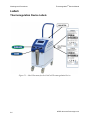
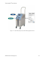


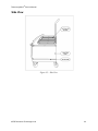
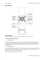


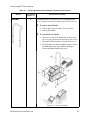
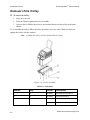
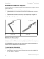


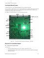
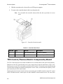
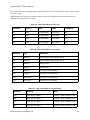
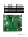
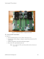
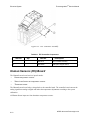
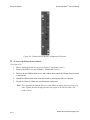
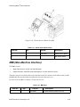
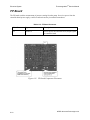

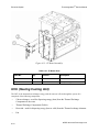


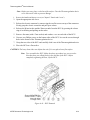
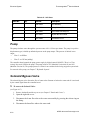
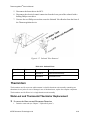
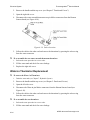


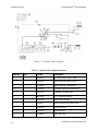
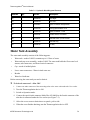
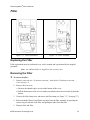
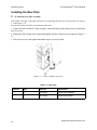

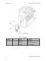

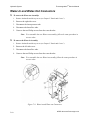
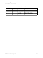


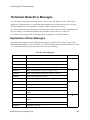
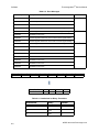
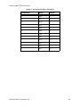


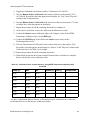

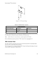

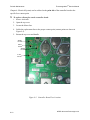
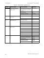
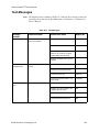
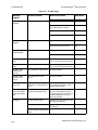


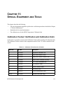
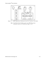
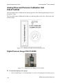

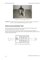


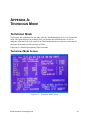


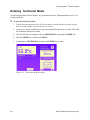
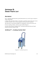
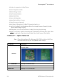


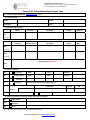


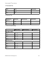
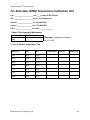
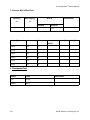


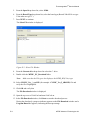
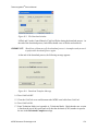


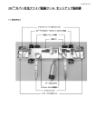
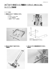
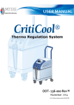


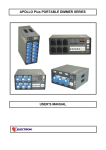
![PDF [1] - Dep SAE Soudage, Automatismes et Electronique location](http://vs1.manualzilla.com/store/data/005888267_1-8c649f384f0a877ffbc023ff9f75566c-150x150.png)