1
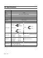
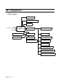
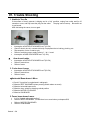
SERVICE MANUAL DIGITAL PANORAMA AND CEPHALO RADIOGRAPH BelmaX CM Notice to person for after-service * Before the repair working, read through this manual. * Take this Service manual with you to the repair. TAKARA BELMONT U.S.A. INC. BelmaX CM Before Repair Repair sometimes might require dangerous working for adjustment, checking, etc. Therefore, repair should be performed by qualified person or any person who receive proper education or training at our company. Please read and understand this service manual. BelmaX CM CONTENTS 01. When you read Service Manual 01-1/1 02. WARNING 02-1/7 03. Preparation for Repair 03-1/1 04. Specifications 04-1/1 05. Component 05-1/1 06. Setting 06-1/1 07. Trouble shooting 07-1/3 08. Treatment of Error Message 08-1/4 09. Wiring Diagram of Printed Board 09-1/2 10. Parts List 10-1/14 11. Contact Information 12. Maintenance Check BelmaX CM 12-1/1 01.INTRODUCTION 1. Read carefully before operation 2. The operating procedure of the panoramic radiography is the basic. Understand before other radiograph. 3. Observe “Warning” and “Prohibition” matters in the service manual. 4. Read the Operation Manual from 1st page in order to prevent any troubles, accidents and etc. 5. When you have any unclear matter during operation, consult with the operation manual. 6. Exemption from Responsibility Be sure to observe the contents of Service Manual. The accident and breakage of this equipment due to an incorrect repair work are out of the scope of our responsibilities. 7. Warranty Period for Equipment The warranty period is one year from the date of purchase. The charge-free warranty will be applied only to the cases that breakage, failure, etc. of this equipment occurred through normal use. 8. Available Period for Repair Parts and Service Parts is 10 years form discontinued of the equipment 9. The redemption period of the equipment is six years. 10.The disposal of equipment is within the scope of responsibilities of the customer. In case to disposal, consult with the dealer you purchased from or with us. BelmaX CM 02.WARNING WARNING For installation, operation, and maintenance, be sure to follow the instructions included in this manual. If the repair is mistaken by any chance, it causes damage and the accident of the equipment. NOTE Details of WARNING are stated as follows in this manual. DANGER Used for the immediate danger that causes death, serious injury, serious destruction of the property and occurrence of a fire. WARNING Used for indirect danger that causes death, serious injury, serious destruction of the property and occurrence of a fire. CAUTION Used for the danger that causes slight injury or medium level of trouble, partial loss of equipment and disappearance of the computer data. NOTE In using equipment, used for the helpful information. BelmaX CM DANGER Liquids on this equipment will cause electric shock accident or equipment damage. This equipment is electric equipment. Keep liquids away from this equipment. DANGER Shock hazard. This equipment is electric equipment and has some high-voltage portions inside. Turn off the power of equipment and unplug power cable from electrical outlet before opening cover of equipment for repair work. DANGER Some repair works involve risks. Only qualified or trained persons may do repair works. DANGER Some repair works involve risks. Service personnel must give instructions to outsiders to stay away from repair work area. WARNING Do not make alterations to medical electronics equipment! Alterations by user are prohibited. Also, relevant pharmaceutical affairs law imposes following regulations on manufacturers. That is, medical equipments need item-specific approval for manufacture, and “application for partial modification approval” is required when making functional changes in medical equipments. So unauthorized alterations are prohibited. WARNING Radiation Protection in Dentistry Comply with the contents of each clause regarding protection against radiation exposure prescribed in relevant medical regulations when installing and using dental X-ray equipments. BelmaX CM WARNING This equipment for radiograph can cause hazard to service personnel if safe exposure conditions and the usages are not complied with. WARNING Be sure to sterilize equipment portions to be touched by patient or operator before starting repair work. After completing the repair work, sterilize equipment portions touched by service personnel. WARNING While repairing, do not place anything that can be an obstacle within the range of equipment. WARNING To avoid damages to equipment, measuring instruments, etc. and electric shock, service personnel must not remove covers of equipment except when necessary. WARNING To avoid damages to equipment, measuring instruments, etc. and electric shock, turn off power of equipment and take extra care not to short-circuit with other circuit when connecting lead wire of measuring instrument to a circuit within the equipment during repair work. WARNING To avoid damages to equipment, measuring instruments, etc. and electric shock, be sure to turn off power of equipment and use the parts specified by us when replacing machine parts and electric parts of the equipment. WARNING BelmaX CM To avoid X-ray exposure due to carelessness, be sure to install lead plate for X-ray protection on X-radiation aperture of X-ray generator when radiating X-rays during repair work. WARNING Be sure to use positioning attachment specified for each exposure mode when positioning patient. WARNING Be sure to make patient and nursing attendant to wear X-ray protective clothing. (Nursing attendant in this sentence means a person allowed by doctor.) WARNING Be sure to operate X-ray exposure switch from outside of X-ray room. WARNING Operator must instruct patient not to move while X-raying. WARNING Watch patient, nursing attendant and equipment constantly while X-raying, and release X-ray exposure switch immediately if you find something abnormal. WARNING Contact the dealer nearest to you when scraping this equipment. WARNING After completing repair work, be sure to turn OFF power for safety. CAUTION BelmaX CM When X-raying patient after completing repair work, take extra care for patient safety when positioning patient. CAUTION Damage etc. inside X-ray generator cannot be repaired on site. Depending on service personnel’s judgment, the equipment will be returned to factory for repair or replacement. WARNING Responsibility for managing the use and maintenance of medical equipments lies with the user (hospital or clinic). This equipment must be used by doctor or qualified person only. As repair or check inside equipment involves risks, contact the company you purchased from. WARNING When earthquake warning is issued, do not use this equipment. After an earthquake, be sure to conduct maintenance check of the equipment and confirm no abnormality before use. Default of the check and/or confirmation can harm patient. WARNING Be sure to set up X-ray room and install the equipment in the X-ray room. WARNING Do not place anything that can be an obstacle within the range of equipment movement. WARNING Concerning to X-raying and approach to equipment must be done under the responsibility of user in case a repairer, a patient, or a nursing attendant use a pacemaker etc, BelmaX CM WARNING Be sure to use positioning attachment specified for each exposure mode when positioning patient. WARNING Be sure to make patient and nursing attendant to wear X-ray protective clothing. (Nursing attendant in this sentence means a person allowed by doctor.) WARNING Operator must instruct patient not to move while X-raying. WARNING Be sure to sterilize and disinfect equipment portions touched by patient or operator after X-raying and at daily closing time. WARNING Contact our sales office nearest to you when scraping this equipment. WARNING After using equipment, be sure to turn OFF power for safety. WARNING Keep everyone out from X-ray room except repairer when radiating X-rays for repair. WARNING To avoid equipment failure, do not rotate arm by hand. BelmaX CM WARNING Do not move patient until arm reset operation completed after X-raying. CAUTION Take extra care for patient safety when positioning patient. CAUTION Take extra care for patient safety when moving sliding unit up and down. CAUTION Do not look straight at positioning laser beam for your safety. Also, give this caution to patient and nursing attendant. CAUTION Do not radiate beam line to patient eye BelmaX CM 03.Preparation for Repair 1. Manual * BelmaX CM Service manual * BelmaX CM Operation manual 2. Measurement Instruments 1) 2) 3) 4) Digital Multimeter Lead Wire for Measurement Measurement Instrument of Insulation Resistance X-ray detector paper 3. Tools 1) Screwdrivers for Cross Recessed Head Screw (Large, Small) 2) Screwdrivers for Slotted Head Screw (Small) (Insulation type) 3) Boxing Screwdriver (6,5,4,3mm) 4) Hexagon wrench 5) Nipper 6) Cutting Pliers 7) Electrical Soldering Iron (Insulation type), Solder 8) Tap 9) Tap Handle 10) Electric Drill 11) Drill 12) Crimping tool 4. Tools for adjustment 1) Test Piece of BelmaX CM 2) Pb Plate for X-ray protection (thickness = 3mm) 3) Filter (brass plate) 4) Aluminum Filter (thickness = 35mm) 5) X-ray detector paper 6) Adjustment tools for equipment 5. Parts for replacement 1) Prepare parts, printed circuit boards, wire-harness, etc. according to the necessity of repair. 6. Others 1) 2) 3) 4) BelmaX CM Prepare screws, nut, crimp terminal, grease, etc. according to the repair. Alcohol for disinfection Clothe Chemicals for cleaning 04. Specifications Digital Panoramic and Cephalometric Radiograph BelmaX CM Model Input Power Power High Tension Generator Exposure Method 120Vac 60Hz 1φ 2.0kW High Tension Generator (100kHz) Manual Tube Voltage Tube Current 60kV~100kV (1kV step) 2.4.6.8.10.12mA (2mA step) X-ray Tube Focal Spot Total Filtration CCD sensor D-052SB(Toshiba) 0.5×0.5mm 2.5mmAl(Min) Both as Panorama and Cephalo Panoramic Exposure Mode Child Adult Orthoradial Lateral Cephalo Maxillary Sinus Frontal Lateral TMJ Frontal Exposure Time Magnification Panorama Maxillary Sinus TMJ Lateral TMJ Frontal Panorama Maxillary Sinus TMJ Lateral TMJ Frontal :7sec/12sec :8sec :3.0sec(×4) :3.0sec(×2) :1.21~1.36 :1.2~1.22 :appr.1.24 :appr.1.88 Positioning Beam Positioning tools Weight BelmaX CM Cephalo Lateral:2.9sec(short time mode) 4sec(normal time mode) Frontal:3.2~5sec Cephalo Lateral & Frontal: 1.1 3 beams Panorama・Maxillary Sinus: Chin Rest+ Head Holding Rod TMJ Lateral・Frontal:Ear Rod ― 417 lb(189 kg) 05. Component 1. Block diagram Digital sensor Motor Driving Power : 24V Cntrol Power Power line ~ SW REG 24V power supply Primary collimator motor Head swing Motor Motor CPU Board Main CPU Borad Inveter Board High tension Voltagr Unit Rotation Driving Motor Y-Axis motor Focus Beam Motor Frankfurt Beam Moter Unit Moving Motor Up and Down break Beam Operetion Panerl Unit Drive motor for Digital Cephalo BelmaX CM 06. Setting Connect an adjustment tools with the main body first. Explanation of the setting content 1. Basic operation 1) Turn the power on. 2) After finishing initialization of the equipment, set Tube Voltage “0kV” ・Press “SELECT Key” and blink the display of tube voltage ・Keep pressing “SELECT DOWN key” 3) Change it setting mode. ・Press “READY” during pressing “SELECT key” 4) Select setting content of the equipment byTECH UP/DOWN key. 5) Blink setting display of equipment by “SELECT” 6) Decide setting content bySELECT UP/DOWN key 7) Release setting mode of the equipment. ・ Press “READY” during pressing “SELECT” key 2. Mode-specific Operations 1) With or Without CEPHALO Setting Mode: OFF/R/L ・ Without Cephalo: OFF ・ With Cephalo on the left: R ・ With Cephalo on the left: L 2) PREHEAT Voltage Setting Mode: 0 ~ 255 Setting of the tube current reference voltage ・ If decreased the value, the rising of tube current becomes slower. ・ If increased the value, the rising of tube current becomes faster. 3) EXHIBITION ON/OFF Setting Mode: ON/OFF Operation mode for exhibition ・ When set to ON, release the equipment setting and press RESET key, the equipment repeats return-to-origin operation and radiograph operation. 4) XRAY COUNT Display Mode Number of irradiations display mode ・When press SELECT key and keep pressing SELECT DOWN key, the number of irradiation will be cleared. 5)POWER OFF ON/OFF Setting Mode: ON/OFF Auto power-off function setting mode When set to ON, the power turns off automatically in five minutes after the final key operation. ・ When set to OFF, the power will not turn off until turning POWER switch to OFF. BelmaX CM ・ 07. Trouble Shooting 1. Unable to Turn On If the surface of circuit protector is bulging and in a “trip” condition, unplug from outlet, wait for 60 seconds or more, and fully insert the plug into the outlet. The plug can be heat up. Be careful not to get burned. After eliminating the cause, turn on again. • • • • • 2. • • • Interception of MOTOR CPU BOARD fuse F1(3.15A) Check if electric wire is in contact with body of equipment due to braking, pinching, etc. Disconnection of wire of rotation axis Defect of switching power supply Defect of INV board Interception of MAIN CPU BOARD fuse F1(3.15A) Arm doesn’t rotate Interception of MOTOR CPU BOARD fuse F3(3.15A) Defect of motor driver Defect of motor 3. Y axis doesn’t move • • • Interception of MOTOR CPU BOARD fuse F2(3.15A) Defect of motor driver Defect of motor 4Horizontal Beam doesn’t Move • Check if it’s position for cephalometric radiograph • Defective REST SW BOARD (when pressing switch makes no sound) • Defective horizontal beam motor • Defective micro switch for detecting vertical position • Defective MOTOR CPU BOARD • Defective CNK BOARD 5. Focus beam doesn’t move • • • • Is it for Cephalo radiograph position? Defect of REST SW BOARD(In case there is no sound when you depress SW) Defect of MOTOR CPU BOARD Defect of CNK BOARD BelmaX CM 6. Body doesn’t move up and down 1) When operating Beam Line Operation Panel • Defective RESET SW BOARD ( No sound when press SW) • Breaking of curl cord • Defective sliding unit elevation motor driver Remove the top cover, turn on power and check the blinking interval of driver’s LED. ◆ Overload protection function (Number of LED blinks: 2 times) 1. Eliminate the cause that hinders the vertical motion (obstacle, overload) 2. Check if it sounds when the operation button is pressed When it doesn’t make any sound, replace BRAKE BOARD 3. Replace the driver ◆ Open-phase protection function (Number of LED blinks: 3 times) 1. Replace sliding elevation motor 2. Replace the driver ◆ Over voltage protection function (Number of LED blinks: 4 times) Under voltage protection function (Number of LED blinks: 5 times) 1. Check if the voltage between MOTOR CPU BARD check pins, CP1 and CP2, is 24Vdc. When the deviation is large, replace SW power supply. 2. Replace the driver ◆ Over speed protection function (Number of LED blinks: 6 times) Defective MOTOR CPU BOARD and replacement Defective MOTOR CPU BOARD Check that output voltage of CP8 varies while pressing UP/DOWN switch. If it does not vary, replace the board. ・ 2) When operating CM switch ・ Defective CM SW BOARD (when pressing switch makes no sound) ・ Defective sliding unit elevation motor driver Remove the top cover, turn on power and check the blinking interval of driver’s LED. After eliminating the cause, turn on power again. ・ ・ Defective MOTOR CPU BOARD Check that output voltage of CP8 varies while pressing UP/DOWN switch. Defective CNK BOARD 7.Primary Slit Doesn’t Move • • • • • Blowout of BEAM MOTOR BOARD fuse F1 (3A) Defective BEAM MOTOR BOARD Defective motor Blowout of MAIN CPU BOARD fuse F3 (3.15A) Defective MAIN CPU BOARD BelmaX CM 8. Head Doesn’t Rotate • • • • • Blowout of BEAM MOTOR BOARD fuse F1 (3A) Defective BEAM MOTOR BOARD Defective motor Blowout of MAIN CPU BOARD fuse F2 (3.15A) Defective MAIN CPU BOARD 9. Unable to Irradiate X-rays • • Check if Motor CPU Board D16 and Main CPU Board D36 light in Ready on. Check which red LED on INV Board lights Error content DL1: LV Lights when output voltage drops abnormally such as output short-circuit. DL2: OV Lights when output voltage rises abnormally DL3: OC Lights when output current rises abnormally. DL4: TH Lights when INV BOARD temperature rises abnormally Response DL1: Check the wiring from INV BOARD to head Check the input voltage between 1 and 2 pins of CN1 when READY ON. 120Vac DL2, DL3: Check between MAIN CPU BOARD check pins CP11 and CP5 (kV), CP14 and CP5 (PREHEAT), and CP15 and CP5 (mA). DL4: Turn off power and recheck 30 minutes later. 2mA 4mA 6mA 8mA 10mA 12mA 60kV 2.82 2.88 2.94 3.00 3.11 3.19 Table 1: Voltage between kV ref CP11 and CP5 70kV 80kV 90kV 3.27 3.71 4.14 3.34 3.78 4.21 3.39 3.84 4.31 3.45 3.91 4.40 3.53 4.00 4.50 3.63 4.09 4.60 Table 2: Voltage between mA ref CP15 and CP5 (Tube voltage is optional) Tube Current CP15-CPCG 2mA 1V 4mA 2V 6mA 3V 8mA 4V 10mA 5V 12mA 6V BelmaX CM 08. Treatment of Error Message When errors occur, error messages will display on operation panel for adjustment. Take proper treatment for the indication. 1. SENSOR UNIT ERROR 1) Sensor is not installed in the proper place Install sensor in the proper place 2.1COL MT: First Collimator Motor Operation Error 1) Abnormality of first collimator detection sensor Adjust the sensor position or replace the sensor 2) Blowout of BEAM MOTOR BOARD F1 (3A) Replace the fuse or BEAM MOTOR BOARD 3) Defective motor Replace the motor 4) Blowout of MAIN CPU BOARD fuse F3 (3.15A) Replace the fuse. Replace MAIN CPU BOARD. 3.HEAD MT: Head Rotation Motor Operation Error HEAD 1) Abnormality of head rotation motor detection sensor Adjust the sensor position or replace the sensor. 2) Blowout of BEAM MOTOR BOARD F1 (3A) Replace the fuse or BEAM MOTOR BOARD 3) Defective motor Replace the motor. 4) Blowout of MAIN CPU BOARD F3 (3.15A) Replace the fuse. Replace MAIN CPU BOARD. 4.INVERTER: Inverter Error 1) Check if MOTOR CPU BOARD D16 and MAIN CPU BOARD D36 light when READY ON. 1. When D16 doesn’t light • Breaking of electric wire of rotary shaft • Defective MOTOR CPU BOARD • Defective MAIN CPU BOARD 2. When D36 doesn’t light Breaking of electric wire of rotary shaft Defective MAIN CPU BOARD Defective MOTOR CPU BOARD 3. When D16 and D36 light Defective K-L1 Defective MOTOR CPU BOARD BelmaX CM 2) Check which red LED of INV BOARD lights. Error contents DL1: LV Lights when output voltage drops abnormally such as output short-circuit. DL2: OV Lights when output voltage rises abnormally DL3: OC Lights when output current rises abnormally. DL4: TH Lights when INV BOARD temperature rises abnormally. Response DL1: Check the wiring from INV BOARD to head Check the input voltage between 1 and 2 pins of CN1 when READY ON. 120Vac When the voltage is lower than 120Vac Breaking of electric wire of rotary shaft Defective K-L1 DL2, DL3: Check between MAIN CPU BOARD check pins CP11 and CP5 (kV), CP14 and CP5 (PREHEAT), and CP15 and CP5 (mA). DL4: Turn off power and recheck 30 minutes later. Table 1. Voltage between kV ref CP11 and CP5 60kV 70Kv 80kV 90Kv 2mA 2.82 3.27 3.71 4.14 4mA 2.88 3.34 3.78 4.21 6mA 2.94 3.39 3.84 4.31 8mA 3.00 3.45 3.91 4.40 10mA 3.11 3.53 4.00 4.50 12mA 3.19 3.63 4.09 4.60 Table 2 Voltage between mA ref CP15 and CP5 (Tube voltage is optional) Tube CP15-CPCG Current 2mA 1V 4mA 2V 6mA 3V 8mA 4V 10mA 12mA 5V 6V 5. THERMAL: Tube Temperature Error 1) As the head temperature is abnormally high, leave the equipment for 30 minutes or more before taking next radiograph. 6. RS CPU: Communication Error with MOTOR CPU BOARD 1) Check the continuity of rotary shaft harness. In case of breaking, replace the harness, use spare wire as a temporary measure. In the case where the continuity exists, replace MOTOR CPU BOARD or MAIN CPU BOARD. BelmaX CM 7. Y MT: Y-axis Motor Operation Error 1) Abnormality of Y-axis detection sensor Adjust the sensor position or replace the sensor. 2) Blowout of MOTOR CPU BOARD F2 (3.15A) Replace the fuse or MOTOR CPU BOARD 3) Defective motor driver Replace the motor driver. 4) Defective motor Replace the motor. 8. ROT MT: Rotation Motor Operation Error 1) Abnormality of rotation detection sensor Adjust the sensor position or replace the sensor. 2) Blowout of MOTOR CPU BOARD F3 (3.15A) Replace the fuse or MOTOR CPU BOARD. 3) Defective motor driver Replace the motor driver. 4) Defective motor Replace the motor. 9. BEAM MT: Indicator Operation Error When indicator (beam operation portion) is operating 1) Replace the sensor. When indicator (beam operation portion) is not operating 1) Replace the motor. 2) Replace MOTOR CPU BOARD. 10. UNIT MT: Planetary Portion Operation Error 1) When operating Beam Line Operation Panel • Defective sliding unit elevation motor driver Remove the top cover, turn on power and check the blinking interval of driver’s LED. After eliminating the cause, turn on power again. ♦ Overload protection function (Number of LED blinks: 2 times) 1.Eliminate causes that hinder the elevation motion (obstacle, overload) 2.Check if pressing operation button makes a sound of brake. When it makes no sound, replace BRAKE BOARD. 3. Replace the driver ♦ Open-phase protection function (Number of LED blinks: 3 times) 1. Replace sliding unit elevation motor. 2. Replace the driver. ♦ Over voltage protection function (Number of LED blinks: 4 times) Under voltage protection function (Number of LED blinks: 5 times) 1. Check if the voltage between MOTOR CPU BOARD check pins CP1 and CP2 is 24Vdc. BelmaX CM 2. Replace the driver. ♦ Overspend protection function (Number of LED blinks: 6 times) 1. Defective MOTOR CPU BOARD Check that output voltage of CP8 varies while pressing UP/DOWN switch. If it does not vary, replace the board. 2)When operating CM switch • Defective CM SW BOARD (when pressing switch makes no sound) • Defective sliding unit elevation motor driver • Remove the top cover, turn on power and check the blinking interval of driver’s LED. After eliminating the cause, turn on power again. Defective MOTOR CPU BOARD Check that output voltage of CP8 varies while pressing UP/DOWN switch. • Defective CNK BOARD BelmaX CM 09. PRINTED CIRCUIT BOARD LAYOUT DRAWING 1. Overall View The printed circuit board assemblies are housed in the portions shown in the drawing. BelmaX CM No. 1 2 3 4 5 6 7 8 9 10 11 12 13 14 15 16 17 18 19 BelmaX CM Board Name DC brushless motor driver Brake board CNK board Motor CPU Board Rotation motor driver Y-axis motor driver Switching power supply NF1 board NF2 board Film motor driver High frequency inverter power supply Head swing motor driver High-voltage generator board Collimator motor board Main CPU board LCD indicator Switch board Beam switch board Vertical motion switch board 10. Parts List 1. Stand BelmaX CM PART LIST: Stand No 0101 0102 0103 0104 0105 0106 0107 0108 0109 0110 0111 0112 0113 0114 0115 0116 0117 0118 0119 0120 Drwing No 408-10311 408-10312 - - 408-10304 408-10305 308-03621 408-10398 408-10399 408-10326 408-10307 977-79030-04 977-79030-08 408-10315 408-10314 408-10318 408-10313 408-10321 408-09036-02 208-01776-03 BelmaX CM Part Name Bracket for securing to wall Bracket for securing to wall High anchor Ø8´50 Coach bolt C8-50 Visor Stand rear cover Weight frame Weight (A) Weight (B) Brake Wire Brushless motor AXH015K-20 Motor driver board Gear (Small) Gear (Large) Pulley (2) Pulley (1) Brake board Stand top cover Stand bottom cover Qty. Hyper-X Hyper-X CM 1 2 2 2 1 1 2 1 1 1 1 1 1 1 2 2 1 1 1 1 2 2 2 1 1 3 1 1 1 1 1 1 2 2 1 1 1 Remarks For Hyper-X only For Hyper-X CM only Alternative Silver Black 2.Sliding Unit BelmaX CM PART LIST: Sliding Unit No Drwing No 0201 0202 0203 0204 0205 0206 0207 0208 0209 0210 0211 0212 0213 0214 0215 0216 0217 0218 408-10156 977-60001-07 964-30012-13 408-10296 962-05006 962-05003 408-08591 978-60007-02 964-28001-02 108-01181 408-10309 408-09751 408-05331 408-09751 408-10253 965-85012-69 965-85012-67 030-03000-01 BelmaX CM Part Name CNK board DC motor TG-38E-LG66 Microswitch ABJ241441 Dog Laser marking projector LDV167LS Laser marking projector LDV167LA Mirror Photomicrosensor EE-SY671 POWER switch A8G-107-1G-24 Sliding unit cover Rear cover Pulley Shaft Roller (2) Membrane sheet Circuit protector 15A Circuit protector 8A Bearing 6000ZZ Qty. Hyper-X Hyper-X CM 1 1 2 1 1 1 1 3 1 1 1 2 4 4 1 2 2 4 1 1 2 1 1 1 1 3 1 1 2 4 4 1 2 2 4 Remarks Horizontal beam Median beam Bundled with 0218 For 100V-spec. For 200V-spec. Bundled with 0213 3.Rotation Unit BelmaX CM P A R T LIS T : R otation U nit No D rw ing N o 0301 0302 0303 0304 0305 0306 0307 0308 0309 0310 0311 0312 0313 0314 0315 0316 0317 0318 0319 974-80057 408-09935-02 408-09935-03 975-00003-03 408-08757-00 408-08758 965-60041-17 408-10151 977-79021-02 977-79024-03 408-10340 308-02560 408-09682 978-60004-04 408-10345 978-60004-10 408-10343 108-01182 108-01183 BelmaX CM P art N am e Switching power supply AWM-1C150SMotor driver board Motor driver board Noise filter GT-215FJ NF(1) board NF(2) board Relay JM1aN-ZTM-DC24V Motor CPU board Stepping motor PK543-NA Stepping motor PK564AN-TG20 Gear (Small) Gear (Large) Ball screw Photomicrosensor EE-SX671 Sensor fin (Y) Photomicrosensor EE-SX673 Sensor fin (R) Rotation unit cover (Top) Rotation unit cover (Bottom) Q ty. H yper-X H yper-X C M 1 1 1 1 1 1 2 1 1 1 1 1 1 2 1 1 1 1 1 1 1 1 1 1 1 2 1 1 1 1 1 1 2 1 2 1 1 1 R em arks Y-A X IS R O TA TIO N Y-A X IS R O TA TIO N Y-A X IS Y-A X IS R O TA TIO N R O TA TIO N 4.Arm BelmaX CM P A R T LIS T : A rm No D rw ing N o 0401 0402 0403 0404 0405 0406 0407 0408 0409 0410 0411 0412 0413 0414 0415 0416 974-10056-01 408-10145 408-10423 408-10416 937-50022-04 408-10419 978-60004-07 408-10415 408-10414 932-21005-18 977-79031-05 408-07586-00 974-80058-07 408-10450 408-10483 408-10486 BelmaX CM P art N am e Q ty. H yper-X 1 1 Stationary plate 1 Angle plate Plunger PBF-10-KSN Sensor fin Photomicrosensor EE-SX672 Pulley (Large) Pulley (Small) Timing belt B 100 S 3M 252 Stepping motor PK266M-02A Motor driver board S w itching pow er supply LDA50 1 CNP BOARD 1 S haft 1 P late spring 1 High-frequency inverter power sup M A IN C P U B O A R D H yper-X C M 1 1 1 1 1 2 1 1 1 1 1 1 1 1 1 R em arks For H yper-X For H yper-X For H yper-X For H yper-X For H yper-X For H yper-X For H yper-X For H yper-X For H yper-X For H yper-X only C M only C M only C M only C M only C M only C M only C M only C M only C M only 4.Chinrest Unit BelmaX CM P A R T LIS T : C hinrest U nit No 0701 0702 0703 0704 0705 0706 0707 0708 0709 0710 0711 0712 0713 0714 0715 0716 0717 0718 0719 0720 0721 0722 BelmaX CM D rw ing N o 408-10152 408-10379 408-10331 408-10381 108-01188 408-10380 408-06071 408-06081 408-06082 408-10396 977-79010-05 978-60011 408-10387 408-10388 962-05006 408-09316 308-02261 408-05861 408-05083-02 308-03599-01/-02 308-03600-01/-02 308-03601-01/02 P art N am e Switch board Frame Membrane sheet Bottom cover Holding portion cover Handle Knob Gear (Large) Gear (Small) Holder guide Stepping motor Proximity sensor Sensor fin Lid Laser marking projector Beam projector mount Rest for bite Bite fork Rest for maxillary sinus Head holding rod Ear rod for TMJ lateral Ear rod for TMJ frontal Q ty. H yper-X H yper-X C M R em arks 1 1 1 1 1 2 1 1 1 1 1 P X 243-03A 1 A P S 4-12S 1 1 1 LD V 167LS 1 1 1 1 1set 1set 1set 6.Head BelmaX CM P A R T LIS T : H ead Q ty. No D rw ing N o P art N am e C M (R ) H yper-x 0501 0502 0503 0504 0505 0506 0507 0508 108-01177 108-01179 108-01178-01 978-600004-13 408-07586-02 977-79010-05 408-10478 408-10479 BelmaX CM X-ray generator Assy Generator cover (Rear) Generator cover (Front) Photomicrosensor Motor driver board Stepping motor Mask (Panorama) Mask (Cephalo) 1 1 1 1 1 1 1 - C M (L) R em arks H yper-X C M H yper-X C M 1 1 1 2 1 1 1 1 1 1 1 2 1 1 1 1 H yper-X C M 7.Cephalometric Radiography Unit BelmaX CM P A R T LIS T : C ephalom etric R adiography U nit Q ty. No 0801 0802 0803 0804 0805 0806 0807 0808 0809 0810 0811 D rw ing N o 408-10243 308-03624-01 308-030652 408-10246 408-1062 408-05027 408-05028 308-03627 308-03626 408-02531-03 988-50054 BelmaX CM P art N am e Mounting plate A rm C ase Membrane sheet CM SW BOARD Ear rod arm Ear rod Forehead H olding R od (2) S econd slit Label CCD sensor C M (R ) C M (L) hyper-X C M hyper-X C M 1 1 1 1 1 2 2 1 1 1 1 1 1 1 1 1 2 2 1 1 1 1 R em arks 11.CONTACT Please contact our sales office or a distributor near you. Belmont Equipment A Division of TAKARA BELMONT USA, Inc. 101 Belmont Drive Somerset, NJ 08873 Toll Free (800) 223-1192 Toll Free Fax (800) 280-7504 www.belmontequip.com TAKARA COMPANY, CANADA, LTD. 2706 South Sheridan Way Mississauga, Ontario, Canada L5J 2M4 Toll Free (800) 268-5351 Fax (905) 822-6203 www.takarabelmont.ca BelmaX CM 12.MAINTENANCE CHECK WARNING High voltage is applied to some parts inside the equipment. Take extra care when removing the case of equipment. Before beginning repair work, turn OFF the power of equipment and unplug from electrical outlet. After unplugged the equipment, wait for 10 minutes or more before starting a repair work. Specialized knowledge, experience and special measuring instruments are required to check this equipment. To maintain the performance of equipment, please perform daily check (with eyes) and implement periodic maintenance by dealer service personnel. Dental X-ray Equipment Maintenance Check List Check Item Electricity Condition Appearance and Indication Installation Place Purpose of Check Check power supply voltage range (1) Appearance of equipment (2) Inside of equipment Temperature, humidity, gas Levelness of equipment Floor and equipment stabilizing condition Check obstacles Operation Test Safety Test for Electric Shock Rust development condition Operation test before check Operation test after check Insulation resistance Leaked current from the outer cover Earthing resistance Resistance of earthing wire BelmaX CM Maintenance by service personnel: 1 or 2 times/year Method Contents of Check Check the compatibility between the power supply voltage connected to the equipment and the specified voltage for the equipment. a. Deformation, flaw, nameplate b. Cautions Check defacement and dust. Check the compatibility of environmental ambient of the place where the equipment will be used. Check the effect on the equipment Check vibration and movement stability of the equipment. Check that there is no obstacle within the movement range of the equipment. Check the condition of rust development functional safety. | | | z z z | | Check operating condition of the equipment. Check operating condition of the equipment. Check resistance between power line and the earth. Check the current leaking from the outer cover of the equipment to the earth. Check the resistance between exposed metal portion of the equipment and the earthing point. Check the resistance between the earth terminal of the equipment and earthing point. z z z z Check Item Operation Accuracy of Equipment Indication during X-ray irradiation X-ray Generator Purpose of Check Check operation of power supply circuit Check operation of radiographic circuit Check operation of operation circuit Accuracy of positioning mechanism Check operation of protection circuit Check operating condition indicator Check irradiation of X-ray and the indication are in sync X-ray tube housing X-ray Output Check the voltage of power supply circuit. z Check the operating waveform and setting values of control circuit. z Check operation of operation sequence. z Check deterioration of the positioning mechanism. z Check the setting values and operating condition of protection circuit. Check the circuit function to indicate the operating condition. z Check leakage of insulating oil. | Low voltage cable Check wear, flaw, tension and twist. | Irradiation cone Check looseness, deformation and damage. | Filter Check coming off and damage. Check off-alignment of irradiation field and irradiation width. | | Check slip, abnormal sound and stopping accuracy. Movement of arm Patient positioning mechanism Light for positioning Play, looseness, operationality and stability. z Check the brightness and position accuracy. | Wire rope Check breaking of wire and end portion. | Check the movement. Braking mechanism Electromagnetic lock Upward and downward movement condition X-ray tube voltage Check smoothness of movement | Check X-ray tube voltage. z X-ray tube current Check X-ray tube current. z Exposure time Check exposure time. z Symbol Checking Method | z Check with eyes Check by using measuring instruments etc. Check by operating the equipment. BelmaX CM z Rotation and movement of X-ray generator Elevating Mechanism Method Check the operation of indicator during X-ray irradiation. Slit Plate (Collimator) Radiographic Mechanism Contents of Check