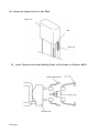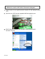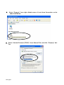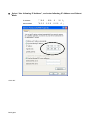
1
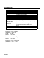
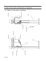
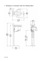
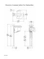
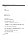
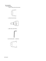
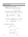
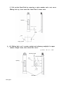
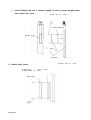
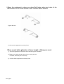
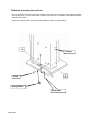
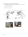
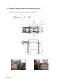
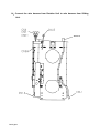
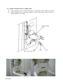
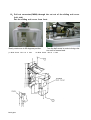
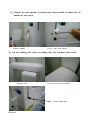
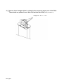
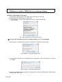
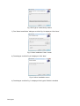
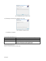
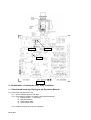
I02-1167E
Installation Manual
Digital Panoramic Radiograph
Bel-Cypher
Notice
★ Read this installation Manual thoroughly before Installation.
The classification is shown as follows
According to the type of protection against electric shock. :
According to the degree of protection against electric shock.
:
Class Ⅰ
Type B applied part
TAKARA BELMONT CORPORATION.
Bel-Cypher
Caution!
This manual provides information and instruction for the installation, assembly, and certification procedures
for the “Bel-cypher” X-Ray.
The instructions contained in this book should be thoroughly read and understood before attempting to
install the “Bel-cypher” unit. After the installation is completed, file this manual and refer back to it
when performing periodic maintenance.
Bel-Cypher
CONTENTS
1. Introduction
01
1 / 1
2. WARNING
02
1 / 2
3. Pre-Installation Instructions
03
1 / 1
4. Specification
04
1 / 1
5. Names of each components, Measurement of equipment
05
1 / 3
6. Checking of each components and accessories
06
1 / 3
7. Installation Procedure
07
1 /15
8. Methods to install LAN Board for Panoramic Radiography
08
1 / 3
9. Methods to install a TWAIN driver in imaging software
09
1 / 3
10. Post-Installation Instructions
10
1 / 5
11. Contact Information
11
1 / 1
12. Revised record of this manual
12
1 / 1
Bel-Cypher
1. Introduction
1. Observe “Warning” and “Prohibition” matters in this Installation Manual.
2. Read this Installation Manual thoroughly to prevent an accident or trouble.
3. If you have any unclear matters in installation, reconfirm it by reading this Installation Manual.
4. After installation, read Operation Manual to understand operation procedures.
5. Discharge
Be sure to observe Installation Manual. If accidents or troubles of the equipment happen due to improper installation, we cannot be responsible for those accidents or troubles.
6. Repair and repair parts supply
Repair and repair parts supply is available for 10 years from discontinued date.
7.
Bel-Cypher
mark means “ Attention, consult accompanying documents “.
2. WARNING
WARNING
Always conform to the safety work standards to assure safety for workers and other people concerned.
Repair work for internal parts of the equipment involves high risk. This should be strictly conducted by an authorized service personnel only.
Meanings
DANGER
Explains danger that may cause serious adverse effect to a human body.
WARNING
Explains an instruction where personal injury or physical damage may occur
CAUTION
Explains an instruction that should be observed for safety reasons
NOTE
States descriptions which serve to improve work efficiency and to help user to understand instructions in
the manual
Bel-Cypher
DANGER
This equipment is electrical instrument. Do not splash water.
Such action causes electric shock or trouble of equipment.
WARNING
This X-ray Unit may be dangerous to patient and operator unless safe exposure factors and operating instructions are observed.
Follow the local zoning authority's regulations regarding X-ray room that you are going to install Bel-Cypher.
2
The floor should have strength of 650N/1 0 0 c m and should be rigid.
This equipment has units which are more than 20kg. Heavy units should be brought up by more than 2
people.
Do not put things in area where equipment functions.
In order to avoid influence by other electric equipment, use separated power source from the other electric
equipment.
Those who install X-ray apparatus should wear X-ray protector apron.
Pay attention when Sliding Unit is moves up and down.
LASER RADIATION, DO NOT STARE INTO A BEAM, CLASS 2 LASER PRODUCT
1.Laser Beam is applied. For safety, instruct patient not to look at the laser beam.
2.Before the beam is lightened, lower Frankfort Line Beam to bottom.
3.Do not set the beam to patient's eyes.
CAUTION
Do not turn ROTATION ARM by hand. It might cause a trouble of the equipment.
Bel-Cypher
3. Pre-Installation Instructions
1. Manuals
1) Installation Manual of Bel-Cypher
2) Operation Manual of Bel-Cypher
2. Measuring instruments and tools
2-1. Measuring instruments
1) Digital Multi Meter with an accuracy of 1%, capable of measuring 150VAC and 20mA DC, and
capable of indicating true RMS value within one second
2) Fluorescent Screen
2-2. Tools
1) Philips Head Screwdrivers (Small and Big)
2) Slotted Head Screwdrivers (Small, Anti-Static type)
3) Nut Drivers (M6, M5, M4 and M3)
4) Ratchet wrench
5) Allen keys
6) Cutting Nippers
7) Long nose nippers
8) Hammer
9) Electric Drill
10) Drill bit 8.3mm = 21/64”(which can drill in wall and a floor )
2-3. Others
1) Ethanol for disinfections
2) Waste Clothe
3) Cleanser
3. User supplied Network Card (NIC) and PC.
NOTE:
IN GENERAL, MAJOR STRUCTURAL MODIFICATIONS ARE NOT REQUIRED,
HOWEVER THE FLOOR ON WHICH Bel-Cypher IS PLACED SHOULD BE ABLE TO
SUPPORT 600 lbs. DEAD LOAD.
3 Electrical Requirements
1) Power Supply
Bel-Cypher X-Ray operates on a power supply of 120 VAC. A three wire GROUNDED circuit, separately connected to the central distribution panel with an over current protection device rated for 15
amperes. Recommended wire size is 12 AWG. But if the wire run distance is to exceed 50 feet, 10
AWG is required. For wire run distance in excess of 75 feet, up to 125 feet, 8 AWG is required.
2) All connections, workmanship and materials used must comply with the national Electric Code and
local codes.
Bel-Cypher
4. Specifications
General name
Model
Digital Panoramic Radiograph
Bel-Cypher
Power Voltage
120Vac 60Hz 1φ
11A
Power Capacity
High Tension
Generator
X-ray Tube Voltage
X-ray Tube Current
Exposure method
X-ray Tube
X-ray Tube Focal Spot
Total Filtration
Radiographic Mode
Exposure Time
Magnification Ratio
Image receiver
Beam for patient positioning
Dimension
Weight
High Tension Generator (100kHz)
60kV to 80kV (1kV step)
2 to 8mA (1mA step)
Manual
D-052SB (Toshiba)
0.5 mm
2.8mmAl (minimum)
Panorama: (Adult, Child), Panoramic Bitewing (Adult, Child)
TMJ:
Panorama: 10 sec. Panoramic Bitewing:4.6 sec.
TMJ: 2.5 sec. (x 4)
Panorama: 1.2 to 1.3, Panoramic Bitewing: 1.2 to 1.3
TMJ: 1.2
CCD Sensor
3 beams
W:920mm x D:1,100mm x H:2,200mm
Approximately 287 lb(130 kg)
Environmental condition for Operation
Temperature : 41~95F (5~35℃)
Humidity
: 30~85%
Pressure
: 700~1060 hpa
Environmental condition for Storage
Temperature : 14~140F (-10~60℃)
Humidity
: 10~95%
Pressure
: 700~1060 hpa
Environmental condition for Transportation
Temperature : 14~140F (-10~60℃)
Humidity
: 10~95%
Pressure
: 700~1060 hpa
Bel-Cypher
Bel-Cypher
Lock Switch
Power Switch
Sliding Unit
Grip
Base
CCD Sensor
Chinrest Unit
Exposure Switch
Control Unit
Rotation Unit
Pillar
X-Ray Generator
Arm Section
5. Name of each parts and Dimension of equipment
1.Names of each parts of equipment
2.Dimensions of equipment (with Free Standing Base)
Bel-Cypher
Dimensions of equipment (without Free Standing Base)
Bel-Cypher
6. Parts and Accessories for equipment
1. Parts for equipment
1) Base
2) Joint Block
3) Pillar
4) Rotation Unit ASSY
5) Rest Unit Assy
6) Weight Assy
7) Look pulley Assy
8) Upper Cover for Pillar
9) Rotation Unit Cover
10) Sliding Unit Cover
11) Fixed Screw of base and joint block
Cap Screw: M10 x 30 (6 pcs.), Spring Washer: φ10 (6 pcs.), Flat Washer: φ10 (4 pcs.)
12) Fixing screws for Joint Block and Pillar
Cap Screw: M6 x 16 (4 pcs.), Spring Washer: φ6 (4 pcs.), Flat Washer: φ6(4 pcs.)
Hexagon socket flat screw: M6 x 16 (4 pcs.), Washer (4 pcs.)
13) Fixing bolts for Sliding Unit ASSY and Rotation Unit ASSY
Hexagon Bolt: M8 x 30 (4 pcs.), Flat Washer: φ8 (4 pcs.), Spring Washer: φ8 (4 pcs.)
Taper Pin: (2 pcs.)
14) Fixing Bolts for Sliding Unit ASSY and REST ASSY
Hexagon Bolt: M5 x 30 (4 pcs.), Flat Washer: φ5 (4 pcs.), Spring Washer: φ5 (4 pcs.)
15) Fixing Screws fro Pillar and Look pulley Assy: Hex-head tapping screw φ4 x 20 (2 pcs.)
16) Fixing Screws fro Rotation Unit Cover
Binder Screw: M3 x 8 (2 pcs.), Nylon Washer: φ3 (2 pcs.)
17) Fixing Screws for Sliding Unit ASSY
Binder Screw: M3 x 16 (4 pcs.), Nylon Washer: φ3 (4 pcs.)
18) Power Cable
Bel-Cypher
Accessories
2-1. Accessories
1) Head Holding Rods (Panorama)
2) Chinrest (Panorama)
3) Bite Block (Panorama)
4) Ear Rods (TMJ / 4 divisions)
Bel-Cypher
2-2. Expendable Supplies
Bite Block Cover
3. X-ray Exposure Switch (with Holder)
4. CD containing TWAIN Driver
Bel-Cypher
7. Installation Procedure
1. Remove packing material cover for Pillar, then remove pillows shown in below
drawing they are used for pillars at installation.
1. 1. (Two pillows)
Put vinyl in the packing or waste clothe on the pillow for protecting scratch of
Pillar. Then, put the Pillar on the pillows(Sliding Unit ASSY is down side).
Pillar without upper cover is shown
Take out pillows and put them
on the floor as shown below
Pillow
Put waste cloth on packing vinyl
on the pillows to avoid scratch
Pillow
2.Remove pillar cover from Pillar Assy
(1): Bind M3 × 6
(2): Nylon washer φ3
2 sets
2 sets
Pillar cover
Bel-Cypher
Pillar assy
3. Mount joint block by Cap Screws to base.
(1): Cap Screw
(2): Spring
M10 X 30
φ 10
(3): Washer
φ 10
6 sets.
6 sets.
(1): Flat head screw M10 X 25 6
6 sets
Free Standing Base Type
Floor Type
4.Attach the Wall Bracket to upper part of the Pillar by 2 flat head cap screws
(1): cap screw
Wall bracket
Bel-Cypher
M6 × 12 2 sets
5.Pull out the Steel Rod by removing a nylon washer and a nut, move
Sliding Unit up, then insert the Steel Rod to lower hole.
Opening
Shaft
Nut
Nylon washer
6.Lift Sliding Unit, set 2 counter weight and adjusting weight(s) in upper
counter weight frame, then attach the cover.
(1): Screw
Adjusting weight
Counter Weights (2)
Opening
Cover
Steel Rod
Bel-Cypher
M4 × 10
2 sets
7.Lower Sliding Unit, set 2 counter weight in lower counter weight frame,
then attach the cover.
Screw
M4 × 10
2 sets
Counter Weights (2)
Opening
Cover
Steel Rod
(1): Screw
8.Attach pillar cover.
(1): Bind Screw
(2): Nylon washer φ3
Pillar cover
Bel-Cypher
M3 × 6
2 sets
2 sets
M4 × 10
2 sets
9 Move the equipment to where you place Bel-Cypher, place two holes of the
wall bracket on the screw thread of the concrete strike anchors.
Tighten M8 nuts.
Confirm that the apparatus is securely fixed.
When coach bolts (diameter = 8mm, length = 40mm) are used
① Move the apparatus to the place where the Bel-Cypher is installed.
②Tighten coach bolts through holes of the mounting bracket.
If needed, drill holes prior to this step
③ Confirm that the apparatus is securely fixed.
Bel-Cypher
10 Method of installing the earth wire
Run the supplied earth wire from the hole located at the bottom of the column to the grounding terminal
in the X-Ray room. Connect Earth Wire to facility Earth Ground in accordance with National Electric
Code and local codes.
Secure the conductor with a screw and a spring washer. Refer to the figure below.
Column
Screw
Spring Washer
Earth Wire
Bel-Cypher
11 Mounting Rotation Unit ASSY on Sliding Unit ASSY
11. 1. By holding carriage holder, with two men, hook the Rotation Unit ASSY onto Sliding Unit.
Align rotation unit by using taper pins.
11. 2. Insert taper pins with a hammer.
11. 3. Tighten and Fix hexagon bolts.
Hook
Rotation Unit ASSY
Pin
(1): Taper Pin
(2): hexagon bolts
(3): Spring
(4):Flat
Bel-Cypher
φ5X25
φ8X25
φ8
φ8
2sets.
4sets.
4sets.
4sets.
12. Remove Carriage Holder from Rotation unit Assy
Take the carriage holder off the rotation unit assembly.
φ8
(1): Nut
(2): Spring Washer
C
Bel-Cypher
M6
φ8
4sets.
4sets.
4
t
13.Connect the wire harness from Sliding Unit to the PC board of Rotation
Unit.
Bel-Cypher
14.Connect the wire harness from Rotation Unit to wire harness from Sliding
Unit.
Bel-Cypher
15.Install Chinrest unit to sliding unit.
15. 1. Align positioning pins of Chinrest Unit ASSY to positioning holes of Sliding Unit ASSY.
15. 2. Attach Chinrest Unit by cap screw ①M5×20 (4 sets), Spring washer ②φ 5 (4 sets) &
③Flat washers φ 5 (4 sets).
Bel-Cypher
16.Pull out connector(CNSM) through the cut out of the sliding unit cover
(Left side)
Put the sliding unit cover from front.
(1): Bind Screw
(2): Bind Screw
M3 X 16
M3 X 8
2 sets.
2 sets.
Slowly rotate arm to 90 degrees position.
(1) Bind Screw M3×16 2 sets
Bel-Cypher
Turn the ball screw in order to bring rotation unit to forward end.
(2) Bind Screw M3×8 2 sets
17.Connect the wire harness of handle assy, insert handle to detent pin, fix
handle by cap screw.
Connect (CNSM)
Fix by a cap screw M6×40.
18.Put the rotating unit cover on rotating Unit, Put Frankfurt plane knob
Attaches cover.
Fix with two truss screws M3×8.
Frankfurt plane knob
Bel-Cypher
19.Remove three hexagon bolts to release brake located at upper part of the Pillar.
These bolts are painted in red. Also Pull out the Steel Rod (refer procedure 4)
Hexagon bolt
Bel-Cypher
M4 × 8 3 sets
20.Attach the Upper Cover on the Pillar
Pillar cover
Hole
Spiral code
21.Insert Chinrest and Head Holding Rods or Ear Rods to Chinrest ASSY.
Head Holding Rods
Chinrest Unit
Bel-Cypher
8.Methods to install a LAN Card for Panoramic radiograph
1.Turn the power of user supplied personal computer off, and unplug the power
cable.
2.Open the cover of PC. Insert an expanded LAN Card supplied by user.
3.Start the personal computer, open Start Menu, right click My Network
and select “Property”
Bel-Cypher
4. Select “Property” from right clicked menu of Local Area Connection on the
added LAN Board.
5.Select “Internet Protocol (TCP/IP)” from General Tab, and click “Property” button.
Bel-Cypher
6.Select “Use following IP Address”, and enter following IP Address and Subnet
Mask.
Click “OK”
Bel-Cypher
IP Address
「192.168.0.101」
Subnet Mask
「255.255.255.0」
9. Methods to install a TWAIN driver in imaging software
Installation of Bel-Cypher Twain Driver
1) Insert the PC power plug into the outlet, and turn the power of PC ON.
2) Set Bel-Cypher TWAIN Driver of Install Disc.
3) .NET Framework 3.5 SP1 setup display such as Fig 1 starts automatically.
Click “Accept”
Fig 1 .NET Framework 3.5 SP1 Setup screen
※In case of .NET Framework 3.5 SP1 is already installed、Fig 1 is not displayed.
4) The Visual C++ Runtime Setup screen such like Fig 2 is displayed. Click “Install”
Fig 2 Visual C++ Run time Setup screen
5) The dialogue such like Fig 3 is displayed. .NET Framework 3.5 SP1 and Visual C++ Run time
is installed.
Fig 3 Visual C++ Run time Install screen
6) After the installation was completed, the dialogue such like Fig 4 Bel-Cypher TWAIN Setup
Wizard starts. Click “Next”
Bel-Cypher
Fig 4 Bel-Cypher TWAIN Setup Wizard
7) The “Select install folder” dialogue such like Fig 5 is displayed. Click “Next”
Fig 5 “Select Installation Folder” screen
8) The dialogue such like Fig 6 is displayed. Click “Next”
Fig 6 Confirm Installation screen
9) The dialogue such like Fig 7 is displayed. Bel-Cypher TWAIN is installed.
Bel-Cypher
Fig 7 Installing Bel-Cypher TWAIN screen
10) The dialogue such like Fig 8 is displayed. Click “Close”.
Fig 8 Installation Complete screen
11) Installation is completed
Recommended specifications of P.C.
CPU
Intel Core2 Duo E6850 (3.00GHz/4MB/1333MHz FSB) or more
Chipset
Intel X38 Express or more
Video Controller
NVIDIA Quadro FX380 256MB or more
Memory
2GB or more
OS
Windows XP Professional SP3 32bit, English Version
Windows Vista Business, 32bit, English Version
Windows 7 Professional 32bit, English Version
Recommended location of P.C.
Place P.C. at least 7 feet away from Bel-Cypher.
Bel-Cypher
10. Post-Installation Instructions
1. Check listed items by referring to the Operation Manual.
1) Measurement of Feedback voltage and tube current
①Make sure the main power is off. Remove covers from Rotation Unit. (Figure 1)
②Cover radiation aperture with lead
③Turn on the power of PC that is connected to Bel-Cypher. Hit Ctrl + Alt + T simultaneously to get
into Test mode.
④Set exposure condition by referring the Operation Manual.
1) Exposure Orbit → Panorama
2) Manual Exposure
3) Tube Voltage: 70kV
4) Tube Current: 8mA
⑤Irradiate X-ray, then measure the feedback voltage between CP11 & CPCG (Tube voltage),and
between CP12 & CPCG (Tube current). (Figure 2)
Bel-Cypher
CP12
CP11
CPCG
Figure 2
2. Confirmation of movement with X-ray irradiation.
2.1. Check listed items by referring to the Operation Manual.
2.2. Confirm the operation with X-ray
2.2. 1. Cover radiation aperture with lead.
2.2. 2. Set exposure condition by referring the Operation Manual.
1) Exposure Orbit → Panorama
5) Manual Exposure
6) Tube Voltage: 60kV
7) Tube Current: 2mA
2.2.3. Irradiate X-Ray and confirm the operation.
Bel-Cypher
3. Check listed items by referring to the Operation Manual
1. Power
1)
Measurement of Input Power
2)
Does 1) meet the rating description on the Controller plate?
3)
Rating Values of the Circuit Protector on the Rotation Voltage
Unit
Current
4)
Are there any problems when the power plug is insert- Heat
ed?
Allophone
Off-flavor
□
□
□
OK
OK
OK
□
□
□
NG
NG
NG
5)
Does the Power Code have a scratch or a crack?
□
OK
□
NG
Bel-Cypher
Voltage
Vac
□
OK
□
NG
V
A
4. Operation
1)
After Power On, does the main body have a problem?
2)
Heat
Allophone
Off-flavor
□
□
□
OK
OK
OK
□
□
□
NG
NG
NG
After depressing the "RESET" key, is “READY” displayed?
□
OK
□
NG
3)
Does the main body move with up / down switch?
□
OK
□
NG
4)
Does up / down operation of main body have a prob- Allophone
lem?
□
OK
□
NG
5)
Does Sliding Unit stop at the highest and the lowest position?
□
OK
□
NG
6)
Positioning Beams in Panorama
6-1) Are all positioning beams turned on by depressing forward / backward switch of Focus Beam?
□
OK
□
NG
□
OK
□
NG
6-2) Dose Forward / backward operation of Focus Beam on ARM work
by depressing forward / backward switch?
Bel-Cypher
7)
Beams in T.M.J.
7-1) Are all positioning beams turned on by depressing forward / backward switch of Focus Beam?
□
OK
□
NG
□
OK
□
NG
Are all positioning beams turned off automatically when forward / backward switch of Focus Beam are not depressed for 1 minute?
□
OK
□
NG
Check in Panorama mode
9-1) Does equipment work normally with exposure op- Allophone
eration at 0kV, 0mA, at Panoramic mode?
Vibration
□
□
OK
OK
□
□
NG
NG
Check in T.M.J.
10-1) Does equipment work normally with exposure op- Allophone
eration at 0kV, 0mA, at TMJ mode?
Vibration
□
□
OK
OK
□
□
NG
NG
10-2) After the first exposure, Does Rotation Arm Unit return to start
□
position automatically.
OK
□
NG
OK
□
NG
7-2) Dose Forward / backward operation of Focus Beam on ARM work
by depressing forward / backward switch?
8)
9)
10)
10-3) After the second exposure, Does Rotation Arm Unit stop at the □
end position.
11)
Does the buzzer sound to facilitate "Turning the Power Switch OFF"
□
in 5 minutes later after the last operation?
OK
□
NG
12)
After power is turned off automatically, Will power turn on again
□
normally?
OK
□
NG
5. Externals
1)
Are there scratches or cracks?
□
OK
□
NG
2)
Are all covers secured with screws?
□
OK
□
NG
Bel-Cypher
11. Contacting information
Belmont Equipment
A Division of TAKARA BELMONT USA, Inc.
101 Belmont Drive
Somerset, NJ 08873
Toll Free (800) 223-1192
Toll Free Fax (800) 280-7504
www.belmontequip.com
TAKARA COMPANY, CANADA, LTD.
2706 South Sheridan Way
Mississauga, Ontario, Canada L5J 2M4
Toll Free (800) 268-5351
Fax (905) 822-6203
www.takarabelmont.ca
Bel-Cypher
12. Revision data of this manual
This manual was created on Oct 2008.
Revised November 2011
Document number :B02-T170
Bel-Cypher