1
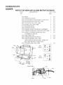
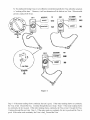
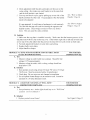
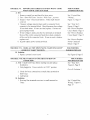
servree Rual MODELS A975 & A980 ~--- '. .. -r"_ ' S.LiJIOHilR.O.i..'tIA'!I live. P.O. Box 25 Boley, Oklahoma 74829 Phone: 918/667-3341 Fax: 918-667-3935 Email: [email protected] Revised 1/06 C---.--==rrE COPYRIGHT 1995 SMOKAROMA, INC. TABLE OF CONTENTS 2005 Description of Models ............................................................................................................. 1 Description of Operation ........................................................................................................ 2 Care and Cleaning of the Instant Burger......................................................................... 2 Parts for A975 and A980 Instant Burger .......................................................................... 3 Description of Parts.................................................................................................................. 4 How the Printed Circuit Board Works ............................................................................. 5 Quick Check for Function Controls ................................................................................... 6 Load Test ...................................................................................................................................... 6 Setting the Board....................................................................................................................... 7 Triacs ............................................................................................................................................. 8 Triac Test ................................................................................................................................... 8-9 Trouble Shooting Outline .............................................................................................. 10 - 12 I. Cooks all the time when lid is closed II. Hamburger overcooking and sticks to top plate III. Hamburger cooks on one side of plate and but not the other IV Have to push start button several times to get hamburger done V Cooks for 5 seconds at "W\!lI-Done" then turns off VI. Power light "green" is on but won't cook when red button is pushed VII. Cooks all the time unless "Rare- W-ll Done" Knob is in rare position VIII. Meat green on one side and raw on the other side How To How To How To How To Replace Triacs .......................................................................................................... 13 Replace Power Connector Block ....................................................................... 14 Replace Circuit Board .......................................................................................... 15 Replace Terminal Block ....................................................................................... 16 How To Adjust Top Handle ................................................................................... 1.6 How To Adjust Top Hinges .................................................................................... 16 Control Box Wiring ................................................................................................................ 17 Limited Warranty .................................................................................... Outside Back Cover DESCRIPTION OF MODELS This service manual is written for models A975 and A980 series. The difference in the two models is that the A980 does not have slide adjustment brackets as it was designed for situations where adjustments are not needed. There is an older model A975 and a newer model A975 . The older model A975 has a "Rare-Well Done" adjustment control (See figure 1.) On the newer model A975, this control was removed (See figure 2.) The degree of doneness is now factory set at "Well Done". This is a requirement of most health departments . Both the older A975 and newer models have slide adjustment brackets for adjusting the thickness of the hamburger. On the A980, the thickness of the hamburger is factory set for a one-quarter pound hamburger and is not adjustable . The A980 has been discontinued since there is so little difference between the A980 and the newer model A975. How do you tell the difference between the models? 1. The older model A975 is readily identifiable by the "Rare-Well Done" knob on the front control panel. If you lift the cover, you will also see adjustment slide brackets for adjusting the thickness of the hamburger. (See figure 1.) 2. Newer models oftheA975 have the "Rare-Well Done" control removed from the printed circuit board. (See figure 2.) Hence it will not appear. However, if you open the cover, you will still see the adjustment slide brackets for adjusting the thickness ofthe hamburger. 3. The A980 may be identified easily because it has neither the "Rare-Well Done" control nor the adjustment slide brackets . IMPORTANT: This service manual is written such that the "Rare-Well Done" control is still on the machine. Anytime this service manual refers to the "Rare-Well Done" control or knob, it will be italicized. If you are servicing an A980 or newer model A975 without the "Rare-Well Done" potentiometer, simply skip the italicized portion and go to the next paragraph or un-italicized portion of the service instructions. Figure 1 Adjustment Knob Figure 2 D CRIPTION OF OPERATION The fnstant represents the In modern technology. It uses a new method to cook the meat. than to heat up an element, to up a griddle, to heat up a the Instant Burger passes energy directly and causes it to heat itself automatically, and in a the time necessary to by ordinary methods. On the newer model control been removed and the control preset at Done". A electronic brain then over and monitors energy to the hamburgers and automatically stops The result is a less fatty a delicious tasting product. This is especially true since no oil or is used to the hamburgers. unit can cook practically of ground or tenderized beef. It can also cook boneless such as rib of round, etc. It can also be to cook, patties and of ground meat. It will also whole precooked chicken breast and hot operation, the hamburgers, either in a patties, are on the bottom The cover is closed. operator " dial bel1veen "rare" and "Degree CARE & CLEANING OF INSTANT BURGER See 3 Proper cleaning is your INSTANT B should wiped clean at end of each service. addition the top and bottom plates, plastic drip should be any time the Instant Burger is to out of servIce more than one hour. These parts be removed and immersed in water for "Operations and Merchandising manual" for proper procedure. should be bed clean or similar pad. All parts may be cleaned soap and water nonabrasive pad. care should taken to make sure no grease or water enters the control housing. be use with a I The model comes equipped single individual circuit, and must 2 3 parts which come in contact with cleaned and according to "Operations Merchandising Manual". HAMBURGER COOKER PARTS FOR NEW A975 & A980 INSTANT BURGER PART NO . DESCRlPTION NO. UNIT REQ . 3 105 3159 3445 3450 3460 3510 3515 3565 3570 3575 3630 TRIAC TERMINAL BLOCK ADJUSTMENT SLIDE BRACKET (A975 ONLY) BOTTOM PLATE A950, A975, A980 TOP PLATE A950 , A975, A980 KNOBS, A950, A975 , A980 BACKING SHEET CONTACT BLADE POWER CONNECTOR BLOCK ASSEtvillLY CONNECTOR BLOCK CONTACTS, A975 , A980 CORD TO CONNECTOR BLOCK AND TO TERMINAL BLOCK 3636 WIRE THRU COIL 3640 JUMPER WIRES FOR TRlACS 3700 CIRCUIT BOARD, A975, A980 2 1 2 1 4 1 2 1 2 1 EA. EA. EA. EA. EA. EA. EA . EA . EA. EA. EA. 3 1 EA. EA. EA . (Both models use the same board . Neither will have " Rare Well Done" Control on it!) 3720 CONTROL BOX, A975, A980 3460 3515 Old Model ....... 0 3445 New Model 3 It -B. ".., - ..... ,. ...., 0 [C] """ ""'" - 8 0 3700(A975 & - 8. ., g ... ""'B"" a .... - EA. DESCRIPTION OF PARTS 1. POWER SWITCH Applies power to Printed Circuit Board 2. HAMBURG ER - CHICKEN SWITCH Se lect hamburger or chicken mode of cooking 3. START SWITCH Starts cooking cycle when pressed 4. GREEN LIGHT Indicates machine is on . 'Nhen sequen ced from green to amber and then back to green, it indicates that pow er has been applied (amber on, f,'Teen off) and then removed (amber off, green on) . In that sequence, it indicates tbat the meat is done IE~~~~~~~~~ ~ 5. AMBER LIGHT Indicates when circuit board tells Triacs to apply power to power connector block and therefore indicates meat is cooking. 6. DONENESS CONTROL U~e d to set degree of doneness from "Rare" 10 "Well Done ". This control v11ill not appear on the A 980 or later model A 9 75. 7. PRINTED CIRCUIT BOARD PART NO. 3700 (A975 & A980) Controls cooking cycle. Beeper signals end of cycle 8. TRlACS PART NO. 3105 Applies power to power connector block for cooking when signaled by circuit board. 9. CURRENT DETECTION TRANSFORMER (MOUNTED ON PC BOARD) Csed to monitor current flow during cooking cycle and feed a reflection voltage to the printed circuit board. 10. POWER CONNECTOR BLOCK ASSEMBLY PART NO. 3570 Applies voltage to (Top Plates) meat when lid is closed. U. TERMINAL BLOCK PART NO. 3159 Provides junction for connecting wires . 12. PLASTIC BACKING SHEET PART NO. 3515 Provides insulation protection between plates and metal cover. Caution: Do not operate unit without this part in place. 4 HOWTH PRIN ED CIRCUIT BOARDS WORKS service person It IS important and how it senses printed circuit operation of the degree doneness. As we said the uses method of direct energy Instant to cook the meat. This means the current through the meat and resistance of meat causes meat only to up. There is a unique permits the printed of The The CIrcuit just slightly The current also the current through peak and then breast It then remembers the cooking action at a preset value below that There are some about operation process. 1. The thinner hamburger the greater the area vV''''''',,", surface, the the flow the ham burger. Hence, you re going to be cooking thin amp breaker if ham burgers. a thickness), larger 2.3 ounce If you do, you risk breaking to squash the umt will also ham burger dO\vTI to draw too much current and trip and the current current to a peak as the meat continues to cook, and resistance become high. Thus the current I drop rather to almost zero amps. The as 31 to 35 amps current can be as this not trip a 30 a few """f'n".1" printed circUlt board is an switch. circuit board two unique circuits on it one for chicken 2. Since the current which goes which are in series with a ofthe current through hamburger meat is presented to the through the current While that may be stated In cooking the same amount of they must same size (portion controlled scoop) in order to cook 3. The plates must parallel to evenly even are the same weight For slide adjustment brackets are on different on each one side will a thicker other. The hamburger than cook quicker the circuit to will done and thinner which was not sufficiently cooked, will warm but may look raw In an increasing current. As long as current is will stay on. As soon as the current printed circuit starts to electricity thus action at the This degree of done ness for nrJll1nj'.ll' he "rare to "well done n. It is important 10 know that "rare" does not mean burnt on the outside and pink in the middle. Since the current flows throughout the hamburger. "rare" mean pink all way the same "well done" means the of done ness all/he way the meat. VU11 \"'IIL. With a little understanding on how a little common sense, the Instant repair. H 5 to QUICK CHECK FOR FUNCTION OF CONTROLS 4. Turn "Rare-Well Done " knob to well done position The following is a method of perfonning a quick check on the rnstant Burger to see if it is functioning correctly. It mainiy consists of visual checks and requires no special tools except a voltmeter. Before performing this test the top needs to be open and the voltmeter prongs plugged into each of the power connector block receptacles. 5. Press "Start" button and amber light should come on and stay on past ten seconds . Voltmeter should read line Voltage. 6. Turn "Rare- Well Done " knob towards the "Rare" position and light should switchfrom amber to green, the beeper sounds and at the same time line voltage should drop to approximately :::ero volts on voltmeter. This should occur at around the 12 o 'clock position of the ''Rare-Well Done" knob. J. Turn "Rare-Well Done" knob to "Rare" position. 2. Depress "Start" switch. 3. Amber light should come on and stay on for approximately four seconds. At the same time voltmeter should read line voltage (J 15 volts). Af ter approximately four seconds amber light should go off and green light come on and the beeper will sound. The voltmeter should drop to approximately zero volts. 7. Turn power switch off, then turn back on. Green "ready" light should be restored and voltmeter should read zero volts at power block. Ifunit performs these tests satisfactorily, then unit is ready to operate . If the unit's power connector block prongs will mate properly with the unit should operate correctly. If not, align prongs. LOAD TEST The "Load Test" is a better test than the "Quick Check" as it provides a definite test as to whether the board and the Triacs are working. The equipment needed is a hair blow dryer of about 1800 watts. This will put a load on the machine of about 16 amps, which is just as little less than that when cooking a 3.2 ounce hamburger. The hair dryer must have a switch with "High," "Medium," "Low" and "Off', in that sequence . There are two tests. First you need to adapt the plug-in of the hair dryer such that it will mate with the power connector block of the Instant Burger. This may be done by attaching two #12 solid wires (the kind used in house wiring) on each end as follows. Strip one end on each wire back 'l4 of an inch. Strip the other end by 1;4 inch. Place yellow slip on connectors on ~ inch end of wire and then crimp. Place yellow slip-on connectors on the blade of the dryer plug. You may have to grind down the blades for the yeUow connectors to fit. To run the first test: This test allows you to test the hamburger circuit. 1. Place the 'l4 inch bare end into the power connector block of the Instant Burger. (Omit steps 3 & 4, if the unit does not have a "Rare Well-Done" Control.) 2. Place the switch on the hair dryer to "High." 3. Place the "Rare Well-Done " Knob in the "Rare " position. Press the "Start" button. The hair dryer should start running. It should stay on approximately 5 seconds and then automatically cutoff by itself. 4. Turn the "Rare Well-Done" Knob to the full ., Well-Done" position. 5. Press the "Start" button, the hair dryer should come on and stay on for at least 10 seconds. (You should count to 10 because, if you attempt to turn it off prematurely during the time, the 5-second timer is still energized and it will not cut off.) 6. After counting to 10, slide the switch on the hair dryer to "Medium." The amber light on the control board should go off and the hair dryer should stop running immediately. If it does, the board is functioning properly on "Hamburger" and the Triacs are functioning properly. (, the dryer comes on immediately without pressing the start button and the position, to "Triac find and replace defective Triac(s). not come on when the button is pushed, the board is most likely Replace it. To run Test: test allows to test the circuit. I. Switch the hair dryer to " 2. Switch "Hamburger/Chicken" switch to "Chicken." 3. Press start button. hair dryer should run. 4. Time for I 0 seconds and then slide switch to . There should be a to "Medium" and the that the amber light goes out slight delay time that you switch the hair and the hair dryer will stop. it occurs, the control board is working fine. Triacs are working fine. adapt the dryer to by itself be by attaching end as follows: both ends on wire back by 'l4 inch. Place yellow connectors on every end (4) of the and crimp. yellow slip on connectors on the blade plug. Place other yellow connectors on two terminals where the cord to the connector block figure 10 part #3630. would normally connect to the terminal block. SETTING THE BOARD Sometimes control board will need in the field. symptom this is when control board stops the cooking and the hamburger is not quite done. The equipment needed is a voltmeter, which will measure volts as low as 0.2 volts or 200 millivolts. to remove to board control are two test points on control board. There is no With the control box facing and looking over the back of control board, the first test box to set in the extreme upper board. board ground only. It is . The second test point is down close to a blue or brown rectangular potentiometer with a test point will be just above rectangle potentiometer and two Plug in control box and turn on power. extreme caution for the potential for being shocked is reset board, place your lead on "GND" test Take a small screwdriver and adjust the adjustment screw on the potentiometer until the meter reads +0.290 ± .005 volts DC with the Well " Knob in the "Well-Done" there is no "Rare-Well Done" the unit in the "Well-Done" position. the at +0.290 .005 volts DC. Do try to set board above voltage in It will cause hamburger to over cook and start stinking. 7 TRIACS The Triacs are the little rectangular objects with 3 prongs on them. There are two Triacs. They are labeled no. 8 in the description of parts. The Triacs are used, in this particular case, as an electronic relay. They are switched on when the red button is pressed indicating that cooking should start The triacs carry the heavy current through the hamburgers and back to the neutral wire. The two Triacs are connected in parallel in order to carry the current needed. The Triacs are forced to carry current equally by forcing one Triacs to conduct a half cycle and the other conduct the opposite half cycle. Triac generally fail closed. When this happens, the unit will cook as soon as the cover is closed without pressing the red button. It will also continue to cook even though the amber light may go off and the beeper will beep signaling what should be the end of the cooking. However, it will continue and to cook the hamburger and they will eventually start to smell. Generally, only one Triac burns out. The one that has failed may be determined by the following test. TRIAC TEST INSTRUCTIONS: 1. Align Triac with small terminal toward you. Set ohmmeter to lowest setting (probably 200 OHMS). Terminals are labeled" I", "2", and "3" with small terminal as "I" and continuing counting clockwise. (Note: The numeral "I", "2", "3" are not marked on the Triac, but are used just to identify the terminals.) 2. Make each test shown in the 3 steps shown (fig. 4). 3. If Triac tests "bad" in anyone of these 3 steps, Triac is bad, discard. 4. If the Triac tests "good" in all 3 steps, Triac is good, keep. Remember, triac must test "good" in all 3 steps to be good. NOTES: 1. Older Triacs (slotted screw hole, one end), "Continuity" meter reading on step No.1 on "good" will read about 28 OHMS. 2. Newer Triacs (round hole, both ends), "Continuity" meter reading on step No.1 on "good" will read about 62 ± 5 OHMS. 3. "Continuity" meter readings on "bad" may be anything, but it is generally about 200 OHMS. 4. "No Continuity" meter reading will generally read "OL" on newer meters and ''1'' on older meters. 5. This method of testing Triacs is very effective in determining defective Triac when the symptom is "cooking all the time." However, it will not determine all the defects in a Triac. When trouble persists, replace both Triacs . Figure 4 Step) - Ifthe meter reading shows continuity, the test is good. lfthe meter reading shows no continuity, the Tnac is bad . Discard the triac. Continue through the next 2 steps. Step 2 - Tfthe meter reading shows no continuity, the test is good. If the meter reading shows continuity, the Triac is bad . Discard the Triac. Continue through the next step . Step 3 - Jf the meter reads no continuity, the test is good and the Triac is good. If the meter reads continuity, the Triac is bad. Discard the Triac. 9 TROUBLE SHOOTING OUTLINE TROUBLE: I. COOKS ALL THE TIME (WHEN LID IS CLOSED). FOR FURTHER INFORMATION SEE A. Test 1. Unit plugged in . Make sure power switch is in "OFF" position. 2. Measure voltage at power connector block. If it reads line voltage (J 15V approximately) then one or both Triac may be defective. B. Solution 1. Check Triacs and replace defective Triac. See "Triac Test", and Figure 4, Page 9 2. "Start" Push button stuck. Unstick or replace circuit board. See Figure 8 & 9, Page 15 TROUBLE: ll. HAMBURGER OVER COOKING AND STICKS TO TOP PLATE. FOR FURTHER INFORMATION SEE A. Test - Cook with hamburger B. Solution 1. Clean plate (shiny) with "Scotch Brite" maroon pad. 2. Make sure "Hamburger-Chicken" switch is in the "Hamburger" position. 3. Test Triacs for bad Triac and replace if defective See "Triac Test", Figure 4, Page 9 See Figure 5, Page 13 4. Check drippings tub and make sure drain slot (wide space on back of tub when bottom plate is in place) is toward back with tub in place. Check tub adjustment steps and make sure they rest on the adjustment slide brackets only. If they are too far to one side and rest on the bottom console, replace tub . TROUBLE: III. HAMBURGER COOKS ON ONE SIDE OF PLATE BUT NOT THE OTHER PROBABLE CAUSE-TOP PLATE NOT PARALLEL WITH BOTTOM PLATE. A. Test 1. Cook using hamburger 2. Observe which side is cooking. Generally the thicker hamburger will cook faster controlling the current thus stopping the cooking before the other side (thinner hamburger) is done. The undone hamburger may be partially cooked and will feel warm to touch but may look raw. 3. Check top plate installation by inserting fingers of the rjght hand on the right side and the fingers or the left hand on the left side underneath stainless steel part of the top plate at the bottom. Exert a little pressure with the fingers, attempting to lift the plate away from the surface of the cover. If the plate moves out from the top cover more than a quarter of an inch, the top plate is not secure in the clips If this is the case, remove the top plate and install correctly. 10 4, adjustment slide and make sure they are on same Also make sure each bracket is in the same hole and slide bracket is not 5, Close top and check top for gap by pulling up on one side of the handle and other If a the to adjusted a appeared, it could cause a hamburger to cook unevenly, side with the will cook first the slightly undone, Check hinges on back of lid to see if their loose. This can cause the same condition. B. Solution 1, Make sure the top plate is installed Make sure that bottom of the top plate mate with the cl ips on the top cover. If bottom side or left side or both rest on top the clips than the grooves the meat will not cook evenly on both sides. 2. Put slide adjustment brackets in some and 3, badly worn plates. 4. Adjust handle or hinges. TROUBLE: VI. HAVE TO PUSH START BUTTON SEVERAL FOR FURTHER Measure voltage at outlet (while not Should be line voltage (115V approximately). 2. Measure voltage at outlet, lfihile voltage should not drop below 1l0V B. Solution 1. Run separate circuit using at least # 10 type THHN wire. Must be protected with a 30 amp 2. Check plug, Be sure wires are not clamped on insulation. 3. Do not operate Instant Burger on an cord. It must be operated on a 30 amp circuit TROUBLE: V. COOKS FOR 5 SECONDS AT "WELL DONE" A. Test 1, Run B. Solution l. Replace FOR FURTHER test. Amber bght should stay on in "Well to B. Solution J circuit board 8, II 15 LIGHT (GREEN) IS ON BUT WON'T COOK TROUBLE: VI. A. 1. " knob to "Well-Done" position. switch (red button). Amber light should 2. 3. "Control Box, "Wiring", J 1, 17 come on. at point where cord to connector block block. Should measure line test test bad, replace. ]f 4. across the tvvo terminals on terminal to connector block then check connector block. Ifwire in cord is 5. 6. TROUBLE: 9 "How to Replace , Page 15 to Replace 15 power connector block. COOKS ALL THE TIME UNLESS "RARE WELL-DONE" B. Solution 1. 8, Page 15 printed circuit board FOR FURTHER both Triacs before starting test and replace in. Power switch is in "OFF" position. to 2. Solution 1 loose connections at small (blue) terminal on on wires to small terminal on 12 "Control Box , Figure 11, 17 HOW TO REPLACE TRIACS (See Fig. 5) POSITION \;\[1 ui\ d"\ TT pnf\.. ONG ' d~ T'C.VI)'IJA.,RD 1h'R()\IT 6-32 SCREW l.iLI > \r I I Figure 5 HEAT SINK 1. Unplug unit. 2. Turn unit upside down and remove control box by removing 4 each 6-32 screws . 3. Turn control box right side up. 4. Remove 2 each 6-32 screws from each Triac. 5. Coat bottom of new Triac with "transistor" silicone grease heat sink compound. This assures good heat transfer from the Triac to the heat sink. 6. With new Triac in hand remove wires individually from terminal.s and place on identical terminal of new triac (See fig. 5) . See "Control box wiring" Figure 11 , page 17 to check correct wiring. 7. Attach new Triacs to aluminum heat sink with 6-32 screws. 8. Replace control box using 4 each 6-32 screws . 9. Turn machine right side up and plug into power source. 10. Perform "Load Test" on page 6. If machine passes "Load Test" then it is ready for operation . 13 HOW TO REPLACE POWER CONNECTOR BLOCK 1. Unplug unit. 2. Tum machine upside down and remove bottom cover by removing 6 each 6-32 screws. Remove connector block baffle by removing 2 each lO-24 nuts. 3. Remove two terminals from connector block. 4. Remove 2 each #6 x 5/8 self tapping screws from connector block. 5. Turn machine rightside up and open lid. 6. Replace old connector block with new one. 7. Turn machine upside down and attach 2 each #6 x 5/8 self tapping screws . 8. Connect two terminals to connector block. 9. Replace connector block baffle with 2 each 10-24 nuts. 10. Replace bottom cover with 6 each 6-32 screws. 11. Turn machine rights ide up and plug into power source . 12. Run "Load Test". (See Page 6.) 14 HOW TO REPLACE CIRCUIT BOARD (See Figure 7, 8 & 9) CIRCUITBOARD PI NO.3700(A975) URU !lT flO.\RD I\F~,1UV1 : [) ---7 ......-H!lSO-{] 6-32 NUT 5. Remove wire through coil by removing yellow terminal from terminal block and pulling end through hole in current transformer. (Note: this terminal is smaller and can be pulled through current coil hole.) 6. Disconnect red receptacle from plug at the bottom ofthe printed circuit board (J 1) ClIRRrNT TRA 'SFOR\fFR 7. Remove "Rare-Well Done" controL knob, part no. 3159, using. 050 hex (allen) wrench to Loosen the set screw holding it to the shaft· Figure 7 ' '[''1,lll'l ;~Jil.\N, 8. Remove 3 each 6-32 nuts holding circuit board. 9. Remove circuit board by pulling out. 10. Replace with board with 3 nuts to hold board in place. 11 . Reconnect red receptacle to plug at bottom of new board (Jl). Old Model- Figure 8 12. Put wire through coil and connect yellow terminal back to correct termu1al on terminal block. (See Figure 8.) 13 . Replace "Rare- Well Done control knob Align in " Well Done " pOSition and tighten set screw with .050 hex (allen) wrench. .J l. Unplug unit New Model - Figure 9 14. Replace control box using 4 each 6-32 screws. 2. Turn machine upside down. 15 . Turn Instant Burger upright. 3. Remove 4 each 6-32 screws from contol box. 16. Plug into power source. 4. Remove control box. 17. Run "Load Test". (See Page 6.) 15 HOW TO REPLACE TERMINAL BLOCK (See Figure 10) 1. Unplug unit. CORDTO COli'{E('1'ORBLOCK PI )1;0. )~ JO POWER CORD PlNO m~ WIRE fHK:. roiL PI. ~\u. 3235 BLACK W1RE TO ! l\11'ER WIRE TOTRI:lC PI \l0 )640 2. Turn machine upside down and remove control box by removing 4 each 6-32 screws. Remove wires from old terminal biock and place on new tenninal block one wire at a time until all wires are on new block. (see Figure 10). 4. Remove 2 each 6-32 screws holding old terminal block to bottom of cabinet and remove old terminal block. 5. Attach new terminal block to cabinet using 2 each 6-32 screws. TERMINALB LOC ~ PLO.3 1!9 Figure 10 6. Check circuit board and terminal block wiring according to Figure 10 & 11. 7. Replace control box using 4 each 6-32 screws. 8. Turn machine right side up and plug into power source. 9. Perform "load test" on page 6. If machine passes "Load Test" then it is ready for operation. HOW TO ADJUST TOP HANDLE Open lid and loosen 1/4- 20 bolt with 7/16" socket wrench. Push handle and bolts to the top ofthe slotted hole. Lightly tighten bolt on both sides. Close cover. Handle catches should be riding on top of bottom console just above the slots. Take a hammer and a piece of wood and tap the top ofthe handle on one side until it just barely latches in the slot. Repeat process for the other side. Open lid and tighten bolts very tight. Close lid to see if it will latch. If it won't, repeat the process. HOW TO ADJUST TOP HINGES If the top hinges are too loose it will allow the top to come up a little bit, when cooking, thereby changing the spacing on the hamburger. This will cause uneven cooking. To adjust the top hinge, loosen both lock nuts on hinge bolt. Use 7/16" "Spin Tite" and 7/16" socket wrench. Tighten 114 - 20 bolt until tight with "Spin Tite" wrench. Loosen one quarter turn. Then, tighten lock nut very tight while holding 114- 20 bolt in place with wrench. Do the same with the other hinge. 16 CIRCUIT BOARD PT. 00. 3700 (A975 &A9W) YELLOW WIRE FROM CIRCUlT BOARD o o Z -I :%I .o "!'j ~. :::i [D c: o ~ .... .... >< -:%I~ -Z ORA~EWlRE FROM CIRCUIT BOARD WIRE THRU COIL,WiTERM" A975 PT. NO. 3635 THIS WIRE MUST RUN THRU HOLE IN CURRENT TRANSFORMER G) TERMINAL BLOCK PT. NO. 3159