1
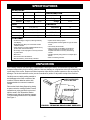
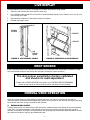
CB700-G1
1
2 3
4
5 6
7 8 9
*
0 #
FEB 2007 • P/N 4215422 • C
CAN/BOTTLE VENDING MACHINE
MODEL 3502, 3502A
SERVICE MANUAL
A11615
TABLE OF CONTENTS
INTRODUCTION ....................................................... 1
SPECIFICATIONS .................................................... 2
Fast Change ....................................................................... 8
Point of Sale Message ....................................................... 8
Target Temperature ........................................................... 8
Keypad Backlight ............................................................... 8
Drop Sensor ....................................................................... 8
Can/Bottle Configuration ................................................... 9
Space To Sales ................................................................... 9
Set Price by Selection ....................................................... 9
Set Price of Entire Machine .............................................. 9
Set Coupon Value .............................................................. 9
Set Token Value ................................................................. 9
Accounting Totals of Entire Machine ............................... 10
Accounting Totals by Selection ........................................ 9
Count Tube Fill ................................................................... 10
Test Single Motor ............................................................... 10
Test All Motors ................................................................... 10
Diagnostics ......................................................................... 10
Relay Test ........................................................................... 10
Electrical ................................................................................. 2
Refrigeration ........................................................................... 2
Size .......................................................................................... 2
Capacity ................................................................................... 2
Features ................................................................................... 2
UNPACKING ............................................................ 2
INSTALLATION ........................................................ 3
Grounding (Earthing) & Electrical ......................................... 3
Power Switch .......................................................................... 3
Door Switch ............................................................................. 3
Hinge & Door Removal ........................................................... 3
LOADING PRODUCTS ............................................. 4
Vend Rack .............................................................................. 4
Live Display ............................................................................. 6
REFRIGERATION .......................................................... 10
DROP SENSOR ........................................................ 6
NORMAL VEND OPERATION ................................. 6
Refrigeration Controls ................................................................. 10
Refrigeration Troubleshooting ................................................... 10
Compressor Will Not Start ................................................ 11
Compressor Trips On Overload ........................................ 11
Noisy or Vibrating Unit ...................................................... 11
Unit Short Cycles ............................................................... 11
Unit Operates Long or Continuously ................................ 11
Refrigerated Space Too Cold ............................................ 11
Refrigerated Space Too Warm .......................................... 12
Troubleshooting Circuits with Multi-Meter ................................ 12
Refrigeration Unit Removal ......................................................... 12
Stand-By Condition ................................................................ 6
Establishing Credit ................................................................. 6
Valid Selection ........................................................................ 7
Vend Sequence ....................................................................... 7
Product Delivery ..................................................................... 7
Sold Out ................................................................................... 7
Resetting Sold-Out Selections ............................................... 7
CONTROLLER PROGRAMMING ............................ 7
Control Board ......................................................................... 7
Sales Mode .............................................................................. 7
Current Temperature ......................................................... 7
Service Mode ........................................................................... 7
Dispense Coins .................................................................. 8
Motor Count ........................................................................ 8
Force Vend .......................................................................... 8
Bill Escrow .......................................................................... 8
Multi Vend ........................................................................... 8
Free Vend ............................................................................ 8
CARE & CLEANING ..................................................... 13
Cabinet Exterior ............................................................................ 13
Cabinet Interior ............................................................................. 13
Refrigeration System ................................................................... 14
ANTI-CHEAT INSTALLATION ..................................... 14
PARTS ORDERING PROCEDURE .............................. 15
BEFORE CALLING FOR SERVICE ............................. 15
SCHEMATIC .................................................................. 16
INTRODUCTION
This manual contains instructions, service and installation guidelines for the CB700-GVC1 Can/Bottle vending
machine. All models are equipped with an electronic control system. All programming of the vend functions,
pricing and features are done at the controller. Changes can be made without any additional accessories or
remote parts.
Selections can be priced individually from $.05 to $99.95 in 5 cent increments (U.S. currency). When adapted to
accept international or foreign currency, the maximum vend price will be 255 times the smallest denomination of
coin being accepted.
MODEL & SERIAL NUMBER
Record the Model and Serial number of your vending machine on the space below. The numbers are on the
identification plate located on the backside of the vending machine. Refer to these numbers on all
correspondence and inquiries concerning this vending machine. They are needed if service and parts
information is required for your vending machine.
FOR U.S.A. UNITS:
MODEL NUMBER:
SERIAL NUMBER:
If you have any questions regarding the information in the manual,
replacement parts or the operation of the vending machine then you
should contact your local distributor or service entity.
-1-
VendNet™
165 North 10th Street
Waukee, IA 50263
PHONE:
PARTS FAX:
SALES FAX:
1-515-274-3641
1-800-833-4411
1-515-987-4447
1-515-274-0390
SPECIFICATIONS
ELECTRICAL
Model
Voltage
Frequency
Current
REFRIGERATION
3502
3502A
115 VAC
230 VAC
60 Hz
50 Hz
9 Amps
5 Amps
Unit Size
SIZE
1/3 HP Hermetically Sealed
Refrigerant
R-134a
Charge
8.5 Oz.
CAPACITY
Height
72 In (183 cm)
Selections
12
Width
42 In (106 cm)
Columns
14
Depth
33 In (84 cm)
12 Oz. Cans
50 per column, 700 total
20 Oz. Bottles
23 per column, 322 total
Weight
750 Lbs. (340 kg)
FEATURES
• On-Board 4 Digit, 7-Segment, Ultra high intensity
LED Display.
• MDB (Multi Drop Bus) coin mechanism and bill
validator interface.
• Piezo "beeper" to provide audible feedback for key
presses and control board activity.
• No change or loss of program or memory because
of power failure.
• Multi Vend.
• First-in first-out for all selections.
• Motorized delivery, electronically controlled.
• Impact sensor delivery system.
• Dual Regulated Power Supplies for logic and motor
control.
• User friendly Service Mode.
• Cash and Vend accountability. Information for
individual selections or total machine can be
compiled and used for inventory and ordering
records.
• Individual product pricing from free vend ($0.00) to
$99.95
• Motor vend testing selection.
UNPACKING
This vending machine was thoroughly inspected before leaving the factory and the delivering carrier has
accepted responsibility for this vending machine. Note any damage or irregularities at the time of delivery and
report them to the carrier. Request a written inspection report from the claims inspector to file any claim for
damage. File the claim with the carrier (not the manufacturer) within 15 days after receipt of the machine.
Carefully remove outside packing material to
avoid damage to the finish or exterior of the
machine. Remove adhesive residue with
denatured alcohol or common household
vinegar.
INSERT SCREWDRIVER
IN SLOT AND TWIST
Remove the Knock-Away Support by placing
a spacer under the vending machine, insert a
screwdriver or prying tool into the grove and
split the wood in two. Discard the washer
located on each side of the wooden supports.
Turn the leveling screws as far in as possible.
See Figure 1.
USE A WOOD BLOCK TO
PROP UP ONE SIDE
A10673
FIGURE 1. REMOVING KNOCK-AWAY SUPPORTS
-2-
INSTALLATION
Consult local, state and federal codes and regulations before installation of the vending machine.
To minimize installation time and to avoid service problems due to improper installation, follow the instructions
outlined in this manual.
Position the vending machine in its place of operation no further than six feet from the power outlet or receptacle
and check that the door will open fully without interference. Leave at least four inches of space between the back
of the vending machine and any wall obstruction for proper air circulation.
CAUTION: Do not block the vent openings in front or in the rear of the vending machine. Always
allow free ventilation behind a bank installation so that exhaust air is not trapped.
Failure to do so could result in refrigeration failure.
Level the vending machine, making sure all levelers are touching the floor. The vending machine must be level
for proper operation. If it is properly leveled, it should not "rock" or "teeter" on any of the levelers. When the
vending machine is level, the door can be opened to any position and not move by itself. Try the door half
closed, straight out and in a wide open position before deciding that the vending machine is level.
Remove all shipping brackets, tape and inner packing
material from the vending machine. Operating the vending
machine without removing the tape and packing material
3-AMP BREAKER
could result in damage to the vending machine.
POWER
GROUNDING (EARTHING) & ELECTRICAL
SWITCH
Prior to connecting the equipment, the integrity of the main
electrical supply must be checked for correct polarity,
voltage, (earth) ground and (amperage) circuit protection.
The fuse or breaker protecting the circuit must be rated at
15 amps or greater.It is recommended that these checks be
repeated at 6 months intervals with the routine safety
electrical testing of the equipment itself. To correct negative
voltage, amperage, polarity or ground (earth) checks,
consult a qualified technician.
A noise suppressor has been installed in this vending
machine to compensate for any signal noise that could
FIGURE 2. POWER SWITCH
interfere with the normal operation of the control board. The
vending machine must be grounded for noise suppressor to
(POWER PANEL)
work.
ON
A10674
WARNING: Do not use extension cords.
POWER SWITCH
A power switch is located on the power panel (bottom left
area with door open), along with a 3 amp breaker. With the
door open, this switch will shut off the light and controller,
leaving evaporator fans running. See Figure 2. The 3 amp
breaker is protection for the controller.
DOOR SWITCH
The vending machine has a door switch operated by the
outer door. It is located in the lower right corner of the
cabinet. When the door is closed, the switched is pushed in
to the ON position, putting the vending machine in the
Sales Mode. When the door is opened, the switch is forced
to the OFF position allowing the vending machine to be put
in Service Mode.
DOOR SWITCH
A11614
FIGURE 3. DOOR SWITCH
LOWER HINGE PIN
RETAINING SCREW
To operate the machine with the door open, the door switch
must be manually pulled out, placing it in an alternate ON
position.
HINGE & DOOR REMOVAL
Removal of the upper hinge or the door from the lower
hinge pin requires removal of the hinge pin retaining
screws. See Figures 4 and 5.
A10857
FIGURE 5. LOWER HINGE PIN
-3-
1. Open the door to approximately straight out
position.
LOWER HINGE PIN
2. Remove upper and lower hinge pin retaining
screws.
RETAINING SCREW
3. Use wooden blocks to support the door. A second
person is required to steady the door. Upper hinge
may now be removed from the vending machine.
4. Lift door from lower hinge. Service as required.
5. Replace door on lower hinge. Support door on
blocks. A second person is required to steady the
door while the top hinge is installed.
A10857
6. Reinstall the hinge pin retaining screw.
FIGURE 5. LOWER HINGE PIN
LOADING PRODUCTS
VEND RACK
IMPORTANT SUGGESTION:
Load the front rack with products that sell faster. When loading, fill
the rear selections first. This method makes it easier to load the rack.
1.
Products featured in front door Live Display
must match the products being loaded.
2.
Funnel slides must be kept clean. Refer to
Figure 7 for part names, locations and
product orientation.
3.
Refer to Figure 7. Product container
bottoms must face towards the center of the
rack as shown.
Do not store bottles in "spare" space of the
cabinet. The refrigeration unit could be
damaged.
A loading chart has been provided on the
inner door to make it easier to keep track of
what types of products have been loaded
into the CB700-G1. Use a dry erase marker
to avoid making a permanent mark.
If refilling with the same product size into the
same column, then load products into the
columns. Skip steps 7 through 11.
4.
5.
6.
7.
If a) loading for the first time, or b) changing
a column to a different product size or c) to
reset product cradle (motor) to correct
position, then load one row of products in
each column and test vend each column
using real money.
CAUTION
8.
FIGURE 6. VEND RACK
Do not load dented or damaged cans or bottles in the columns. Possible jams could occur.
Add five (5) rows of products in each column to check product spacing. Products should have 1/4 to 1/2 inches of
free space at the front or back of the columns. See Figure 7. See step 9.
-4-
THE VEND RACK HAS BEEN SET AT THE FACTORY
FOR MOST 20 OZ BOTTLES OR 12 OZ CANS
SEE STEP 9 TO VEND OTHER TYPES OF CONTAINERS
BACK SPACER
BACK SPACER
BACK SPACER
1/4" TO 1/2"
1/4" TO 1/2"
TYPICAL
20 OZ
TYPICAL
20 OZ
CENTER FILLER
CENTER FILLER
SINGLE
DEPTH
SETTING
TYPICAL
CONTOURED
10 OZ
CENTER FILLER
TYPICAL
12 OZ CAN
TYPICAL
20 OZ
TYPICAL
20 OZ
DOUBLE
DEPTH
SETTING
TYPICAL
12 OZ CAN
1/2" MAX
1/4" TO 1/2"
1/4" MIN
LIFT UP
LIFT UP
PULL
PULL
DIMPLE MUST CLEAR
SLOT OPENING
SMALL
SCREWDRIVER
SLOT OPENING
SLOT
OPENING
DIMPLE MUST CLEAR
SLOT OPENING
NOTCH
MARKER
LATCH STRIKER
(LEFT SIDE)
GATE ASSEMBLY
(RIGHT SIDE)
A10886
FIGURE 7. COLUMN DEPTH
9.
VEND RACK ADJUSTMENTS:
Adjust the back spacer, latch striker or gate assembly to achieve the required dimension. The Vend Rack
has been factory set for most 20-oz. bottles or 12-oz. cans. There are a wide variety of water bottle sizes.
Avoid vending containers that collapse on itself when stacked. Test vend before using. Call service for
additional can/bottle vending information and suggestions.
If vending 16.9-oz water bottles, remove Filler (4211816) shipped inside the Delivery Box and install it in
the Vend Rack. Follow instructions on Filler decal.
ADJUSTING THE BACK SPACER:
Lift the back spacer and reposition it in the adjustment slots. Use notch markers as reference points to
align it vertically. See Figure 7.
ADJUSTING THE LATCH STRIKER AND GATE ASSEMBLY:
Pull and lift up on the lower end of the gate assembly (or latch striker). Use a small screwdriver as a wedge
to gently pry the dimple away from the slot opening. See Figure 7. Reposition them in the adjustment slots.
Use notch markers as reference points to align it vertically.
10. If product spacing is correct, then test vend each column using real money.
11. Load the columns to full capacity.
-5-
LIVE DISPLAY
Products featured in the front door Live Display must match the products being loaded.
1.
Open the main cabinet door, then open the inner door.
2.
Use a Phillips Head screwdriver to loosen the 6 screws holding Display Cover. Slide the cover up, lift it out
and carefully set it aside.
3.
Place product containers on the shelves of the Live Display.
4.
Reinstall the Display Cover.
SCREWS
6 PLACES
PRODUCT
PRODUCT
A11619
LIVE
DISPLAY
COVER
A11618
FIGURE 8. LIVE DISPLAY COVER
FIGURE 9. PRODUCTS IN LIVE DISPLAY
DROP SENSOR
A drop (vibration) sensor on the delivery chute detects if a product has been vended after a selection is made.
The control board located on the back of the main door controls the sensor sensitivity.
The drop sensor sensitivity is factory calibrated
and should not need adjustment.
Please refer to DROP SENSOR instructions in the CONTROLLER PROGRAMMING
section of this manual to restore the drop sensor sensitivity to factory settings.
NORMAL VEND OPERATION
1. STAND-BY CONDITION
When the control board is in Sales Mode the display will show "ICE COLd" or the amount of credit. If a
customer presses a selection before establishing a credit, the vend price for that selection will display signaling
the customer that more money is needed for that selection.
2. ESTABLISHING CREDIT
Feeding coins into the coin mechanism or bills into the bill validator results in the display of the corresponding
credit value. The coin mechanism or bill validator will accept money until the highest vend price has been
reached or exceeded. At this point a credit has been set up through the control board that will enable a vend for
any selection less than or equal to the established credit.
-6-
3. VALID SELECTION
Making a selection on the keypad causes the control board to determine if a vend motor is available and if enough
credit is established. If both conditions are met then a vend is initiated.
4. VEND SEQUENCE
The control board then distributes 24 volts DC through the door and cabinet wiring harnesses and to the coil of
the selected product cradle motor. At the same time, the display will flash. This indicates to the customer that a
vend is in progress. As the product cradle motor receives power, it will turn the product cradle attempting to
vend a can or bottle.
5. PRODUCT DELIVERY
As the can or bottle drops onto the product delivery chute, impact or vibration allows the drop sensor to send a low
voltage signal to the control board indicating that the product has been vended. After receiving the drop sensor signal,
the control board will recognize how the vending machine is programmed and responds accordingly. Refer to
CAN/BOTTLE menu section on page 2 for additional features.
6. SOLD OUT
The display will blink to show the vend process of each selection. If a product drop is not detected in 10 to 12 seconds,
"MAKE ANOTHER SELECTION" light turns on. This condition may be due one of the the following:
• Column is actually sold out.
• Selected column is jammed.
• Wrong selection number.
• Drop Sensor does not detect product drop which may be an indication of a faulty Drop Sensor. Perform a
DIAGNOSTICS routine (page 2) and a test vend.
If "MAKE ANOTHER SELECTION" indicator light is turn is on, the customer may make a different selection or receive
a refund by pressing the coin return lever. If the machine is set for forced purchase, the customer must make an initial
selection. If the selection is sold out, a full refund or an alternate selection will be allowed.
7. RESETTING SOLD-OUT SELECTIONS
Opening the machine door activates the door switch and will clear a sold out condition. The controller will not attempt a
vend until this is done. Pressing a selection button will only initiate the "Sold Out" display.
CONTROLLER PROGRAMMING
CONTROL BOARD
This vending machine has a GVC1 control board that is connected
to product cradle motors. It is also connected to a drop sensor
(impact vibration) for delivery detection.
Open the main door and then open the inner door. The control
board is located on the back of the main door (top middle). See
Figure 11.
SALES MODE
FIGURE 10. DISPLAY
The vending machine defaults to sales mode when it is turned on.
While it is in sales mode, the display will show "ICE COLd". If there
is credit to the customer, it will display the amount of credit.
CURRENT TEMPERATURE
STEP
1
Press 0 to view the temperature sensor reading.
SERVICE
MODE
BUTTON
DISPLAY
36F
POWER
ON LIGHT
SERVICE MODE
Pressing the service mode button while the vending machine is in
sales mode will activate service mode. It will display the number of
working motors.
While in service mode, the control board will automatically revert to
sales mode after one (1) minute if a keypad button is not pressed.
DEX JACK
(OPTION)
NOTE: Always watch display readout after pressing the
Service Mode button or keypad button.
A11545
-7-
FIGURE 11. SERVICE
MODE BUTTON
DISPENSE COINS
FORCE VEND
Manually dispense coins from the coin mechanism.
STEP
1
2
3
Press Service Mode Button
Press 1 .
.
4
5
6
Press 2 to dispense quarters (10¢).
Press 3 to dispense nickels (5¢).
Press
twice to exit.
Press 1 to dispense quarters (25¢).
This feature would require the customer to purchase an item from the
vending machine once credit equal to or greater than the highest
selection price has been deposited.
DISPLAY
14
Coin
.25
.10
.05
ICE COLd
STEP
MOTOR COUNT
Displays the total count of working motors.
STEP
1
Press Service Mode Button
2
3
Press 2 and wait a moment.
Press
twice to exit.
.
DISPLAY
14
14
ICE COLd
STEP
Press Service Mode Button
Press 3 .
3
4
Press 3 .
Press 3 to toggle ON or OFF.
5
6
Press # to save.
Press
three times to exit.
.
Note: NULn = NO (OFF), NULy = YES (ON).
DISPLAY
14
OPtn
NULn
NULy
ICE COLd
Press Service Mode Button
Press 3 .
3
Press 5 .
Press 5 to toggle ON or OFF.
.
Note: FChn = NO (OFF), FChy = YES (ON).
three times to exit.
STEP
Press Service Mode Button
Press 3 .
DISPLAY
14
OPtn
FChn
FChy
ICE
COLd
three times to exit.
Press Service Mode Button
Press 3 .
Press 2 .
.
DISPLAY
14
OPtn
ESCy
Press 2 to toggle ON or OFF.
ESCn
Note: ESCn = NO (OFF), ESCy = YES (ON).
5
Press # to save.
6
Press
ICE
COLd
three times to exit.
.
DISPLAY
14
OPtn
36F
Press 8 repeatedly until 36F is displayed.
Press # to save.
three times to exit.
2
3
Press Service Mode Button
Press 3 .
Press 4 .
4
Press 4 to toggle ON or OFF.
5
Press # to save.
6
Press
.
DISPLAY
14
OPtn
FrEn
FrEy
Note: FrEn = NO (OFF), FrEy = YES (ON).
ICE
COLd
three times to exit.
STEP
ICE COLd
1
2
Press Service Mode Button
Press 3 .
.
3
4
Press 7 .
Press 7 to toggle ON or OFF.
5
Press # to save.
6
Press
DISPLAY
14
OPtn
POSy
POSn
Note: POSn = NO (OFF), POSy = YES (ON).
ICE
COLd
three times to exit.
KEYPAD BACKLIGHT
This menu controls the intensity level of the keypad backlight.
STEP
Restores the Drop Sensor sensitivity to factory calibrated setting.
STEP
3
4
5
6
Press
For Can/Bottle Machines Only. Turns OFF (or ON) the default flashing
display message.
DROP SENSOR
1
2
6
POINT OF SALE MESSAGE
ICE COLd
Press 8 .
Press
Press # to save.
1
Restores the target temperature to factory setting.
5
6
5
FrcY
Note: Frcn = NO (OFF), Frcy = YES (ON).
FREE VEND
TARGET TEMPERATURE
4
Press 1 to toggle ON or OFF.
STEP
1
2
2
3
4
DISPLAY
14
OPtn
Frcn
This feature allows the customer to vend any selection item for free.
STEP
1
Press 1 .
4
Allows the vending machine to give change immediately after the
customer makes a selection. If Fast Change is ON, it will override the
Multi Vend feature.
Press
3
1
2
3
FAST CHANGE
6
Press 3 .
STEP
1
2
Press # to save.
2
.
This feature will hold a bill in escrow (mechanically) until either a vend
is performed or the return credit lever is pressed. This prevents the
customer from using the vending machine as a bill changer.
Multi Vend feature will hold the change (credit), allowing the customer to
make more than one vend provided there is sufficient credit remaining.
5
Press Service Mode Button
BILL ESCROW
MULTI VEND
4
1
Press Service Mode Button
.
Press 3 .
Press 0 to view current setting.
Press 0 repeatedly until "drP1 " is displayed.
Press # to save.
Press
three times to exit.
1
DISPLAY
14
OPtn
drP1
ICE COLd
2
3
4
-8-
Press Service Mode Button
Press 3 .
.
Press 9 to view the setting.
Press 9 to again and again to change setting.
Note: bL 0=OFF, bl 1= Low, bl 2=Med, bl 3=High, bL 4=Max.
5
Press # to save.
6
Press
three times to exit.
DISPLAY
14
OPtn
bL 3
bL 0
ICE
COLd
CAN/BOTTLE CONFIGURATION
SPACE TO SALES
CAn - Can setting is normally used with double-depth loading of cans to
double the product capacity of that selection. During a vend, the product
cradle stops rotating as soon as the drop sensor detects a vend. This is to
prevent double vending.
bott - Bottle setting is normally used with single-depth loading of bottles.
This setting allows the product cradle to continue rotating a few more
seconds so that it is positioned closer to the loading zone. This reduces
the customer's waiting time when the product cradle is activated for the
next vend.
The controller has been configured to operate as a CB700 can/bottle
vending machine and all selections are set to vend cans. Follow the
steps below to restore the controller to a can vending machine, or to set
all or some selections to vend bottles.
STEP
1
2
Press Service Mode Button
Press 4 .
.
3
To set all selections press 3 then go to step 4.
To set a selection, go to step 6.
4
Press 1 to toggle the setting until CAn (or bott )
is displayed. Do not select SnAc.
Note: CAn = Can, bott = bottle, SnAc = Snack.
5
Press #
to save setting then go to step 6
to set selections or go to step 11 to exit.
6
To set a selection, press 1 then wait a moment.
7
8
Press selection number on keypad.
Press 1 to toggle the setting
between CAn (can) or bott (bottle).
9 Press # to save the setting.
10 Go to step 7 to set more selections.
11 Press
StSY - Space to Sales is factory set to on (Y = ON) for the CB700 vending
machine. This means that columns 1-2 are assigned to selection 10 and
columns 3-4 are for selection 11.
STEP
1
2
3
4
5
DISPLAY
14
CbS
ALL
CAn
DISPLAY
14
CbS
StSn
Press Service Mode Button
.
Press 4 .
To restore Space to Sales configuration press 7 .
Press 7 to toggle the setting to StSY.
StSY
Note: StSn = Space to Sales OFF, StSY = Space to Sales ON.
Press # to save setting.
10 Press
ICE
COLd
three times to exit.
SET PRICE
BY SELECTION
CAn
CbS
ALL
Each
-CAn
Press Service Mode Button
Press 5 .
5
Enter new price of selection.
To erase, press
then go to step 5.
6
bott
--
DISPLAY
14
Prc
EAch
-.75
STEP
1
2
3
4
.
Press 1 and wait a moment.
Press selection number on keypad.
7
8
Press # to accept price.
9
Press
Repeat steps 4 thru 7 for other selections.
ICE
COLd
four times to exit.
ICE
COLd
three times to exit.
SET TOKEN VALUE
STEP
SET PRICE
OF ENTIRE MACHINE
STEP
1
2
3
Press Service Mode Button
.
Press 5 .
Press 3 and wait a moment.
4
Enter new price on keypad.
5
6
To erase, press
then repeat step 4.
To accept, press # .
7
Press
DISPLAY
14
Prc
ALL
.75
ICE
COLd
four times to exit.
DISPLAY
14
Prc
1
2
3
Press Service Mode Button
Press 5 .
Press 5 .
.
4
Press 1 thru 5 to select token number.
5
6
Press # to view or set price/value of token.
Enter new price/value of token.
7
8
To erase press
9
Repeat steps 4 thru 8 to set price values of other tokens.
thn1
1.00
and repeat step 6.
Press # to accept token price.
10 Press
thnl
ICE
COLd
three times to exit.
ACCOUNTING
SET COUPON VALUE
STEP
STEP
DISPLAY
14
Prc
CPn1
1
2
3
Press Service Mode Button
Press 5 .
Press 4 .
4
5
Press 1 thru 5 to select coupon number.
Press # to view or set price (value) of coupon.
6
Enter new price (value) of coupon.
7
To erase, press
8
9
Press # to accept coupon price.
CPn1
Repeat steps 4 thru 8 to set price values of other coupons.
10 Press
.
TOTALS BY SELECTION
1.00
and repeat step 6.
three times to exit.
ICE
COLd
-9-
Press Service Mode Button
.
1
2
Press 6 .
3
4
5
Press 1 .
Press the selection number.
Press 1 for total non-resettable vend count.
6
Press 2 for total non-resettable cash value.
7
8
Press 3 for total resettable vend count.
Press 4 for total resettable cash value.
9
Press 5
# to clear the resettable counters.
10 Press
and go to step 4 for other selections.
11 Press
four times to exit.
DISPLAY
14
Acct
EACH
-0
0.00
0
0.00
Clr?
Clrd
Acct
ICE
COLd
ACCOUNTING
TOTALS OF ENTIRE MACHINE
STEP
1
Press Service Mode Button
2
Press 6 .
Press 3 .
3
4
5
.
Press 1 for total non-resettable vend count.
Press 2 for total non-resettable cash value.
6
7
Press 3 for total resettable vend count.
Press 4 for total resettable cash value.
8
Press 5
9
Press
# to clear the resettable counters.
four times to exit.
TEST SINGLE MOTOR
STEP
DISPLAY
14
Acct
ALL
0
0.00
0
0.00
Clr?
Clrd
ICE COLd
1
2
3
4
5
The coin mechanism will keep track of the exact number of each coin as
coins are added through the coin insert. Denominations do not have to be
added in order. The control board will keep track of each coin as it is paid
out.
4
Press Service Mode Button
.
Press 7 .
Add 5 coins of each through the coin insert:
25¢, 10¢ and 5¢. Total coin value is displayed.
Press # to save.
5
Press
1
2
3
twice to exit.
1
2
3
Press Service Mode Button
.
Press 9 . Motor selection number will display
while it is being tested.
Press
twice to stop test and exit.
Press Service Mode Button
.
Press 0 .
Press 1 to perform a self diagnostic test.
4
Press
1
2
.25
3
4
ICE COLd
STEP
1
2
3
three times to exit.
RELAY TEST
DISPLAY
14
tUFL
TEST ALL MOTORS
STEP
Press selection number on keypad.
Repeat step 3 to test other selections.
Press
twice to stop test and exit.
DIAGNOSTICS
COIN TUBE FILL
STEP
Press Service Mode Button
.
Press 8 and wait a moment.
5
STEP
Press Service Mode Button
.
Press 0 .
Press 2 .
Press 1 to display compressor relay1 status.
Press 1 to turn ON the compressor relay.
Press 1 again to turn it OFF.
DISPLAY
14
SLct
-ICE COLd
DISPLAY
14
dIAG
tESt
ICE COLd
DISPLAY
14
diaG
rLY
rL1o
rL1c
CAUTION:
Once the compressor has been turned off, wait 3
minutes before turning it on again to prevent
possible damage to the compressor.
Note: rL1o = relay1 switch contacts open (OFF).
rL1c = relay1 switch contacts closed (ON).
DISPLAY
14
ALL
6
ICE COLd
Press
4 times to exit.
ICE COLd
REFRIGERATION
REFRIGERATION CONTROLS
The target temperature setting for the refrigeration system has been preset at the factory. Refer to TARGET
TEMPERATURE in the CONTROLLER PROGRAMMING section (page 1) of this manual. If setting up for the first
time, please allow sufficient time for the refrigeration system to cool the produczts.
WARNING: Colder setting does not cool drinks faster and may cause drinks to freeze.
REFRIGERATION TROUBLESHOOTING
CAUTION: Do not place any object in the evaporator assembly area or inside the cabinet area that will
block the airflow because this may damage the refrigeration system, which may void the
refrigeration warranty.
CAUTION: Breaking the refrigerant joints or seals on the system voids the unit warranty. Failure to
keep the condenser coil clean and free of dirt, dust and other similar debris voids the unit
warranty.
If the refrigeration unit is turned off or the power is interrupted or the door is opened then the
refrigeration unit will not start for at least three (3) minutes regardless of the temperature. This is done to
prevent damage to the refrigeration unit.
Know and understand how to service the unit and how it operates. Units may vary but the operation is basically
the same. Never guess at the problem. Find the symptom before attempting any repair.
NOTE:
90% of refrigeration problems are electrical.
Unauthorized work done to the sealed hermetic system will void the warranty. The sealed hermetic system is not
to be worked on outside the Factory Service Center. The three (3) things that can go wrong with a sealed system
- 10 -
1. Low Charge - usually
caused by leaks. Look for
oil around seals and
welds. Unit will not cool
properly. The capillary
tube will be frosted before
it enters the evaporator
inlet tube.
DO NOT STORE
PRODUCTS HERE
KEEP AREA OPEN
FOR PROPER
AIRFLOW AND
PROPER VENDING
OPERATION
2. Restriction in System (unit
frosts, then melts) - not
cooling properly.
3. Bad valves - unit does not
cool properly or noisy
compressor.
FIGURE 12. REFRIGERATION
COMPRESSOR WILL NOT START
a.
b.
c.
d.
e.
f.
Vending machine not plugged in.
Tripped breaker or blown fuse.
Faulty wall outlet.
Short or tear in power cord.
Improper wiring.
Low voltage: 5% below. Check the power source with
the Multi-Meter.
g. Overload defective: Trips too fast. Check overload with
the Multi-Meter.
h. Start relay defective. Check start relay with the MultiMeter.
i. Compressor has open windings. Check compressor
windings with a Multi-Meter.
j. Defective thermistor.
COMPRESSOR TRIPS ON OVERLOAD
a. Improper voltage: 5-10% above, 5% below. Check
power source with Multi-Meter.
b. Overload defective: Trips too fast. Check overload with
Multi-Meter.
c. Relay defective: Won't open after starting. Check relay
with Multi-Meter.
d. Compressor has shorted windings: Check compressor
windings with Multi-Meter.
e. Short in other component: Isolate and eliminate each
electrical component until short is found.
f. Compressor is too hot.
•
Dirty condenser.
•
Faulty condenser motor or blade.
•
Restricted airflow.
CAUTION: Condenser must be kept clean of dirt and debris to allow for proper air circulation.
NOISY OR VIBRATING UNIT
a. Components rubbing or touching each other.
• Check fan blades and motor.
• Loose shrouds and harness.
• Copper tubing.
• Loose or unsecured parts.
b. Worn or aged grommets.
c. Compressor
• Bad valves.
• Slugging.
• Bad windings (see Figure 13)
• Low voltage.
UNIT SHORT CYCLES
• Temperature setting too warm. See Refrigeration Controls section in this manual.
UNIT OPERATES LONG OR CONTINUOUSLY
a. Air flow restricted:
• Faulty evaporator motor or blades causing coils to
ice over.
• Loose connections on evaporator motor. (One motor
not running).
• Air flow blocked by product in front of evaporator or
air duct t openings.
b. Gasket leak around main door.
c. Gasket leak around delivery door.
d. Excessive load: After loading, unit will run longer to pull
out excessive heat from product.
e. Shortage of refrigerant or restriction.
REFRIGERATED SPACE TOO COLD
• Target temperature set too cold.
- 11 -
REFRIGERATED SPACE TOO WARM
a. Target temperature set too warm.
b. Restricted evaporator space.
• Evaporator motor or blades faulty, causing the coils to ice
over the evaporator.
• Condenser airflow restricted.
~ Plugged or dirty condenser.
~ Condenser motor or blades bad.
~ Blade stuck.
• Condensing space restricted.
~ Unit placed too close to a wall.
• Compressor - bad valves.
~ Cap tube will start frosting 8 to 10 inches past
evaporator connection tube.
~ Check for oil around brazed connections.
• Leak around delivery door gasket.
TROUBLESHOOTING CIRCUITS WITH MULTI-METER
a. Check the power source. Use voltage section of the MultiMeter. Should measure within 5-10% above, 5% below.
b. Check overload.
Note: Power must be off and fan circuit open.
Using the resistance section of the Multi-Meter, check
terminals 1 and 3 for continuity. If no continuity is measured
(infinity), overload may be tripped. Wait 10 minutes and try
again. If still no continuity, overload is defective.
WARNING:
c. Check relay. See Figure 13 shown below. Unscrew lead
terminals and remove relay from compressor. Keep relay
upright.
d. Check terminals 1 and S, or L and S with the Multi-Meter.
Replace relay if continuity exists.
e. Check compressor windings. See Figure 13 shown below.
f. Check winding resistance with the Multi-Meter. If readings are
not within 2 Ohms the compressor is faulty.
Wiring diagram must be followed as shown. Wrong wiring can cause serious electrical hazard and
potential damage or rupture component electrical parts.
WINDING RESISTANCE
Approximate resistance reading across
terminals - use RXI scale.
COMMON to START:
COMMON to RUN:
RUN to START:
COMMON to SHELL:
1
L2
L1
GND
GROUND
CONDUCTOR
8 Ohms
C
3
OVERLOAD
CONDENSOR
FAN MOTOR
RELAY
R
M
1.2 Ohms
COMMON
9 Ohms
No Continuity
L
S
S
RUN
START
A10115
FIGURE 13. COMPRESSOR SCHEMATIC
REFRIGERATION UNIT REMOVAL
The refrigeration unit is a hermetically sealed and completely self-contained modular unit charged with ozone friendly R-134a refrigerant.
The complete refrigeration unit can be removed if there is a service problem.
WARNING:
Disconnect power before servicing.
1.
Unplug the CB700-G1 power cord from the electrical wall
outlet.
2.
Remove and save the 3 screws holding the Hopper. See
Figure 14.
Carefully remove the Hopper and set it on the right side
while avoiding not to damage the Drop Sensor or its cable
harness.
Remove and save the Condenser Filler Cover and the 4
screws. Refer to Figure 15.
Remove and save the Refrigeration Line Cover and the 2
screws.
Remove the save the sealant.
3.
4.
5.
6.
7.
8.
REMOVE & SAVE 3 SCREWS
Remove and save the 4 screws screws located on the front
(bottom and right) of the condenser assembly.
Remove and save the 4 screws of the Power Panel. Move
the Power Panel to the left side.
A11617
FIGURE 14. REMOVE HOPPER SCREWS
- 12 -
REMOVE CLAMP SCREWS & CLAMPS.
MOVE TEMPERATURE SENSOR TO THE SIDE.
REMOVE EVAPORATOR SCREWS
(7 PLACES). PULL ON EVAPORATOR
UNIT & REFRIGERATION UNIT AT THE
SAME TIME.
REMOVE SEALANT
COVER SCREWS.
REMOVE BOTH
COVERS.
REMOVE
HOPPER
BRACKET
SCREWS
(2 PLACES).
REMOVE
BRACKET.
REMOVE PANEL SCREWS (6 PLACES).
MOVE PANEL ASIDE.
A11616
SET HOPPER
TO RIGHT SIDE.
REMOVE REFRIGERATION SCREWS
(4 PLACES). PULL REFRIGERATION
UNIT & EVAPORATOR UNIT AT THE
SAME TIME.
FIGURE 15. SET HOPPER ASIDE & REMOVE SCREWS
9.
Remove and save the two (2) screws holding the Hopper Bracket in place. Remove and save the Hopper Bracket.
10. Remove the screws and clamps that attach the Temperature Sensor to the Evaporator. Move the sensor to the right side.
11. Remove and save the three (3) screws that attach the Evaporator to the Air Duct.
12. Carefully unplug and move wire harness and cables out of the way of the Refrigeration Unit.
13. Grip the front lip of the Condenser base and the Evaporator base and pull out at the same time. See Figure 15.
14. To reinstall the refrigeration unit, reverse the steps.
CARE & CLEANING
WARNING:
ALWAYS DISCONNECT POWER BEFORE CLEANING.
CABINET EXTERIOR
Wash with a mild detergent and water, then rinse and dry thoroughly. Polish occasionally with a quality car wax. Plastic
exterior parts may be cleaned with a quality plastic cleaner.
CABINET INTERIOR
CAUTION:
DO NOT GET CLEANING SOLUTION ON ELECTRICAL COMPONENTS.
Wash with a mild detergent and water, then rise and dry thoroughly. Including baking soda or ammonia in the cleaning
solution may eliminate odors. Plastic parts may be cleaned with a quality plastic cleaner. Remove and clean Condensate
Drain Hose to eliminate any deposits that may restrict condensate water flow.
Vend mechanism must be kept clean. Any build-up of syrup deposits can cause the mechanism to malfunction. Use soap
and water with great care so as not to get water into the electrical components.
To insure proper vending keep delivery slide area free of dirt and sticky substances.
- 13 -
REFRIGERATION SYSTEM
CLEAN REFRIGERATION INTAKE SCREEN - Remove screen and clean dust and debris from screen using a soft bristle
brush or a vacuum cleaner.
CLEAN CONDENSER COIL & REAR EXHAUST SCREEN - Remove the Cover Assembly and clean the condenser coil
of the refrigeration unit using a soft bristle brush or vacuum cleaner.
Pull the refrigeration unit and clean the rear exhaust screen of dirt and debris.
Do not block the evaporator or any area of the airflow with product or supplies.
ANTI-CHEAT INSTALLATION
WARNING:
Disconnect electrical power to avoid electrical shock when performing service. Do not
remove electrical components or parts without first unplugging the power cord from the
power source.
1. Unlock and open the vending machine Front Door. Open the Inner Door by separating it from the Front
Door.
2. Find the Delivery Box on the bottom right corner of the Front Door as viewed from behind the Front Door.
Remove the Delivery Box from the Front Door by removing the mounting nuts on the right, bottom and left
sides of the Delivery Box. See Figure 17.
NUT
NUT
LEFT VIEW
DELIVERY BOX
RIGHT VIEW
NUT
BOTTOM VIEW
FIGURE 17. REMOVE THE DELIVERY BOX
3. Remove the four (4) nuts holding the Delivery Bezel and save them for step 4. Insert the Anti-Cheat through
the Delivery Bezel rectangular hole. See Figure 18.
4. Mount the Anti-Cheat slotted mounting holes over the mounting bolts of the door as shown in Figure 19.
Reinstall the nuts saved from step 3 and tighten them.
5. Reinstall the Delivery Box.
6. Close the Inner Door to the Front Door. Plug the machine's power cord to the wall outlet and turn on the
power.
7. Close the Front Door and perform test vends.
FIGURE 18. ANTI-CHEAT
(FRONT VIEW)
- 14 -
FIGURE 19. ANTI-CHEAT
(REAR VIEW)
PARTS ORDERING PROCEDURE
PLEASE HAVE THE FOLLOWING INFORMATION:
•
• The model number and serial number of the
vending machine.
•
• Correct part number and description from the
•
pertinent part and/or parts manual.
•
If you do not have the correct parts manual, go
•
online to www.vendnetusa.com or contact
VendNet™ and we will provide a copy for you.
•
Note: Unless specified otherwise, when "right" or "left" are used as
a description in a part name, it is defined to mean that the person is
facing the vending machine with the door closed.
Shipping address.
Address where the invoice should be sent.
The number of parts required.
Any special shipping instructions.
Desired carrier: air or air special, truck, parcel post
or rail.
If ordering by mail, need signature and date.
If a purchase order number is used, be sure that it
is visible and legible.
PARTS ORDER OPTIONS:
• Go online to www.vendnetusa.com. Browse the
parts manuals. Place a secured order online using
your credit card or Vendnet™ account.
• Phone:
USA & Canada ................. (888) 259-9965
International ...................... (515) 274-3641
• Email: [email protected]. Please note
that this is not as secured as playing an order
online.
• Fax Order: ......................... (515) 274-5775
• Mail Order:
VendNet™
165 North 10th Street
Waukee, IA 50263
USA
BEFORE CALLING FOR SERVICE
PLEASE CHECK THE FOLLOWING:
• Does your vending machine have at least 4" of
clear air space behind it?
• If the power is turned on at the fuse box, is the
vending machine the only thing that doesn't work?
• Is the vending machine plugged directly into the
outlet?
WARNING: Do not use extension cords.
Extension cords cause problems.
• Is the evaporator coil free of dust and dirt?
• Is the condenser coil free of dust and dirt?
• Is the compressor free of dust? A blanket of dust
can prevent the compressor from cooling off
between workouts.
• Is the circuit breaker at the fuse box reset?
• Are evaporator lines running? Take a sheet of
paper approximately 4" x 5" in size. Place the
paper in front of the evaporator coil and see if the
evaporator fans will draw the paper to the coil.
• Is the condenser fan running? Fold a sheet of 81/2" x 1" paper in half. Place the paper in front of
the condenser coils and see if it draws the paper to
it.
• Is the shelf in front of the evaporator coil clear?
There must be no tools or other air restricting
items.
• Is the cold control set between 0 and 2?
NOTE: Setting the cold control at a colder
temperature does not accelerate
cooling of product and may cause
product to freeze.
TO CALL FOR SERVICE
• Have model number and serial number.
• Call phone number listed below.
VendNet™
165 North 10th Street
Waukee, IA 50263
United States of America
The contents of this publication are presented for informational purposes only, and while every effort has been made to ensure their accuracy, they are not to be
construed as warranties or guarantees, express or implied, regarding the products or services prescribed herein or their use or applicability. We reserve the right to
modify or improve the designs or specifications of such products at any time without notice.
- 15 -
NEUTRAL
(RIBBED)
COMPRESSOR
RELAY
F
OVERLOAD
S
M
- 16 -
M
6
5
4
3
2
6
5
4
3
2
7
6
5
4
3
2
7
6
5
4
3
2
NC
NC
1
8
8
J1
9
9
NC
1
10
10
NC
J2
11
11
KEY
12
12
NC
DIODE BOARD 2
1
7
7
J1
8
8
1
9
9
J2
11
10
10
12
11
12
DIODE BOARD 1
C
NC
KEY
START
RELAY
S
COMPRESSOR
MOTOR
3
2
EVAPORATOR FAN
2
STARTING
CAPACITOR
1
CONDENSOR
FAN
BLK-WHT
F
1
SMOOTH
(HOT)
WHT-BLK
4214684
CAB.TEMP. SENSOR
KEY
NC
NC
NC
NC
NC
NC
KEY
YEL-BLU
DOOR SW
4214800
COMPRESSOR RELAY CABLE
YEL-BLU
PNK-RED
PNK-BLK
YEL-ORG
PNK-RED
PNK-BLK
4214728
SENSOR/RELAY HARNESS
GRN
YEL-ORG
DEX OPTION
CB700-GI SCHEMATIC
SCHEMATIC