1
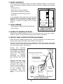
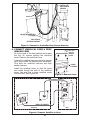
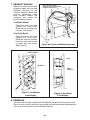
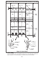
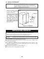
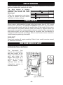
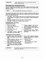
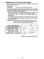
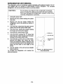
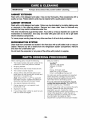
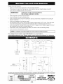
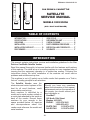
FEB 2006 • P/N 4215155 • B
CAN DRINK & CAN/BOTTLE
SATELLITE
SERVICE MANUAL
MODELS 3505/3505A
(GVC1 HOST CONTROLLER)
CAN DRINK
CAN/BOTTLE
TABLE OF CONTENTS
INTRODUCTION ....................................
SPECIFICATIONS ..................................
UNPACKING ...........................................
INSTALLATION .......................................
INSTALLATION CHECKLIST .................
DROP SENSOR ......................................
1
2
2
3
10
11
VEND CYCLE .........................................
REFRIGERATION UNIT .........................
CARE & CLEANING ...............................
PARTS ORDERING PROCEDURE ........
BEFORE CALLING FOR SERVICE .......
SCHEMATIC ...........................................
11
11
16
17
17
17
INTRODUCTION
This manual contains instructions, service and installation guidelines for the Can
Drink or Can/Bottle Satellite Vendor.
Read this manual thoroughly to become familiar with the features and functions
of this machine. The initial se-up of a vending machine is a very important step of
insuring that the equipment operates in a trouble-free manner. Following the
instructions during the initial installation of the machine will avoid service
problems and minimize set-up time.
This machine is a six (6) select can or bottle vendor that operates on a "first-in,
first-out" vending principle for all selections.
The Satellite Vendor uses the
electronics and control systems of the
host for all vend functions, credit
accumulation and pricing.
Each machine is identified by a
model and a serial number written on
a serial plate attached to the inside or
back of the vendor. Record these
numbers for your records in the
space provided below. All inquiries
and correspondence about this
vendor must reference the model and
serial numbers.
Should you have any questions
about the information in the manual,
replacement parts or the operation of
the vendor you should contact your
local distributor or:
VendNet™
165 North 10th Street
Waukee, IA 50263
PHONE: 1-515-274-3641
1-800-833-4411
PARTS FAX:
1-515-274-5775
SALES FAX:
1-515-274-0390
-1-
MODEL NUMBER:
SERIAL NUMBER:
SPECIFICATIONS
UNPACKING
This machine was thoroughly inspected before leaving the factory and the
delivering carrier has accepted this vendor as their responsibility. Any damage or
irregularities should be noted at the time of delivery and reported to the carrier.
Request a written inspection report from the claims inspector to file any claim for
damage. File the claim with the carrier (not the manufacturer) within 15 days after
receipt of the machine.
Carefully remove the outside packing material in a manner not to damage the
finish or exterior of the machine. Inspect the machine for concealed shipping
damage. Report any damage hidden by the shipping material directly to the
delivering carrier on a Hidden Damage Report.
Record the model number and
INSERT SCREWDRIVER
serial number for your records.
IN SLOT AND TWIST
Space is also provided above.
Remove the "knock-a-way"
support by placing a 2x4 under
the vendor. Insert a large
USE A WOOD BLOCK TO
screwdriver or prying tool into
PROP UP ONE SIDE
the groove of the "knock-away" and split it in two. See
Figure 1. Turn the leveling
screws in as far as possible.
A10673
Figure 1. Remove Knock-Away Supports
-2-
INSTALLATION
Consult local, state and federal codes and regulations before installation of the
vendor.
Follow the instructions outlined in this manual to minimize installation time and
avoid service problems due to improper installation.
Position the vendor in its place of operation no further than six feet (6 ft) from the
power outlet or receptacle and check that the door will open fully without
interference.
Leave at least four inches (4" in) of space between the back of the machine and
any wall or obstruction for proper air circulation.
CAUTION:
Do not block the ventilating screens in front or in the
rear of the vendor. Always allow free ventilation
behind a bank installation so that exhaust air is not
trapped. Failure to do so could result in a
refrigeration failure.
Level the vendor, making sure all levelers are touching the floor. The vendor
must be level for proper operation. If it is properly leveled, it should not "rock" or
"teeter" on any of the levelers. When the vendor is level, the door can be opened
to any position and not move by itself. Try the door half closed, straight out and in
a wide open position before deciding that the machine is level.
Remove all shipping brackets, tape and inner packing material from the vendor.
Operating the vendor without removing the tape and packing material could
result in damage to the vendor.
1. GROUNDING (EARTHING) & ELECTRICAL
IMPORTANT:
Refer to the Safety Manual and Installation Guidelines
(P/N 4206816) that shipped in the service package with
your machine.
Prior to connecting the equipment, the integrity of the main electrical supply
must be checked for correct polarity, presence of ground (earth) and correct
voltage. It is recommended that these checks be repeated at 6 month
intervals with the routine safety electrical testing of the equipment itself.
Consult a licensed electrician to correct negative voltage, amperage, polarities
or ground (earth) checks.
For proper operation of any equipment utilizing electronically controlled
components, the equipment should be placed on an isolated or dedicated
noise free circuit, properly polarized and grounded. Refer to the Electrical
Specifications on this sheet to determine circuit amperage and protection.
WARNING:
Do not use extension cords.
-3-
2. PARTS CHECKLIST
Find the service package envelope inside the Satellite Vendor on the second
(2nd) shelf near the hopper. Remove it and verify that it contains the following
parts:
• Umbilical Cord
• Drop Sensor Cord (umbilical)
• Drop Sensor Extension Harness
• Tie Bracket and Mounting Screws
• Wire Ties
If so equipped, also verify that you have the
optional Filler (rectangular shaped plastic)
attached on the back of the inner door. It
might be needed if vending 16.9 oz water
bottles.
3. TOOLS NEEDED
• Flat Head and Phillips Head screwdrivers.
• Wire Cutters.
HOST VENDOR
SATELLITE
A10879
Figure 2. Satellite
On Right Side of Host
4. SATELLITE VENDOR LOCATION
Position the satellite vendor so that it is on the right side of the host vendor.
Refer to Figure 2. Swing the doors open and check for clearance.
5. INSTALL DROP SENSOR EXTENSION HARNESS
Open the host vending machine door. Find the umbilical box located on the
bottom right towards the back of the cabinet. See Figure 3.
Plug the end with the panel mount connector of the drop sensor extension
harness to the cutout hole. Attach with wire ties to the motor harness only and
not to the power cable. See Figure 3.
Route
the
harness
through the large hole on
the partition, otherwise
route under the partition.
Route the drop sensor
extension
harness
alongside the existing
door harness. See Figure
3.
Plug the other end of the
harness to the drop
sensor harness from the
controller. See Figure 4.
Use wire ties provided to
secure the new harness
to the existing door
harnesses. Use wire
cutters to trim excess wire
ties.
DROP SENSOR EXTENSION HARNESS
SECURE WITH WIRE TIE
TO MOTOR HARNESS
NOT TO POWER CABLE
MOTOR
HARNESS
POWER CABLE
PANEL MOUNT
CONNECTOR
UMBILICAL BOX
Figure 3. Install Drop Sensor Extension
Harness To Umbilical Box
-4-
A11605
CONTROLLER
DROP SENSOR
HARNESS
SECURE WITH WIRE TIES
(3 PLACES)
DROP SENSOR
EXTENSION HARNESS
A11606
Figure 4. Connect to Controller Drop Sensor Harness
6. CONNECT UMBILICAL CORD & DROP
SENSOR CORD
Go to the back of the host cabinet and loosen
the four (4) screws holding the umbilical
cover. Remove the umbilical cover.
Locate the umbilical harness and drop sensor
cord (from inside the service pack envelope).
Plug both the umbilical harness and drop
sensor harness.
Install the umbilical cover so that the cords
are routed though the side of the umbilical
cover. Use wire ties to keep umbilical cords
from the floor. See Figure 6a.
LIFT UP &
PULL TO
REMOVE
COVER
LOOSEN
4 SCREWS
A11574
Figure 5. Remove Cover
DROP SENSOR CORD
UMBILICAL HARNESS
A11573
CB300-SATL
HOST
Figure 6. Connect Satellite to Host
-5-
7. PRODUCT DISPLAY
Make sure that the price and
selection labels are set and
installed correctly on the
Product Display. Labels and
product containers must
face outward toward the
customer and match the
products being loaded.
INSTALL WIRE TIES TO KEEP
UMBILICAL CORD AND DROP SENSOR
HARNESS FROM THE FLOOR
Can/Bottle Model:
Open the main door and
unlatch the inner door.
Slide the can or bottle into
position. See Figure 7.
Can Drink Model:
Open the main door and
unlatch the inner door.
Slide the can into position
from the rear and secure
in place with the strap.
See Figure 8.
A11607
Figure 6a. Secure Umbilical Harness
PRICE SCROLLS
CANS
PRODUCTS
PRICE
SCROLLS
A11501
A11578
Figure 7. Can/Bottle
Live Display
Figure 8. Can Drink
Live Display
8. POWER UP
Connect both the host vendor and the Satellite Vendor to their power source.
Refer to host vendor manual for grounding and electrical power requirements.
Turn on the host vendor and the Satellite Vendor.
-6-
9. MOTOR COUNT
A motor count must be performed
on the host vendor controller for
the controller to recognize the
motors on the Satellite Vendor.
The total number of working motors
should increase by 6.
10. SET PRICES
Set prices for selections 80
through 85 in the same manner
you would set prices for existing
selections. Refer to the host
vendor instruction on programming
prices or follow instructions at right
to set price by selection.
STEP
1
Press Service Mode Button
.
2
Press 2 and wait a few seconds.
3
STEP
1
2
Press Service Mode Button
Press 5 .
3
4
5
Press 1 .
6
7
8
9
.
Press selection number on keypad.
Enter new price of selection.
To erase, press * then go to step 5.
Press # to accept price.
DISPLAY
40
Cnt
46
0.00
DISPLAY
40
Prc
EACH
.75
--
Repeat steps 4 thru 7 for other selections.
Press * twice to exit.
0.00
11. SET SATELLITE (ROW 8) TO CAN OR BOTTLE
When connecting the satellite to
the host controller for the first
time, row 8 must be set to can
or bottle.
Note: The host controller is originally
factory configured so that all
selections are snack. Setting the
entire row 8 to can or bottle
ensures that satellite selections
80 thru 85 operate as a can or
bottle and not a snack.
STEP
1
2
3
4
5
Press Service Mode Button
Press 4 .
.
Press 2 .
Press 8 to select row 8.
Press 1 to toggle to bottle or can.
Do not select SnAc.
DISPLAY
40
CbS
ro SnAc
CAn
Note: CAn = Can, bott = bottle, SnAc = Snack.
6
Press # to save.
ro 0.00
7
Can (CAn) - normally used with double-depth loading of cans to double the
product capacity of that selection. During a vend, the product cradle stops
rotating as soon as the drop sensor detects a vend. This is to prevent double
vending.
Bottle (bott) - normally used with single-depth loading of bottles. This setting
allows the product cradle to continue rotating a few more seconds so that it is
positioned closer to the loading zone. This reduces the customer's waiting
time when the product cradle is activated for the next vend.
12. SET SELECTION TO CAN OR BOTTLE
If there will be a mixture of can
and bottle selections, then
individual selections will need to
be configured.
Note: Only when row 8 has been
configured to can or bottle in
step 11 can each selection be
set individually to vend can or
bottle.
STEP
Press Service Mode Button
Press 4 .
3
Press 1 and wait 2 seconds.
4
Press selection number 80 on keypad.
5
Press 1 to toggle bottle or can vendor.
bott
6
Press # to save.
--
7
Repeat steps 4 thru 6 to set selections 81-85.
8
-7-
.
DISPLAY
40
CbS
C b
-CAn
1
2
Note: CAn = Can, bott = bottle
0.00
13. LOAD PRODUCTS
IMPORTANT SUGGESTION
Load the front rack with products that sell faster. When loading, fill the
rear selections first. This method makes it easier to load the rack.
1. Products featured in the front door Product Display must match the product
being loaded.
2. Filler slides must be kept clean. Refer to Figure 9 for part names, locations
and product orientation.
3. Product container bottoms must face towards the center of the rack as
shown. Refer to Figure 10.
4. Do not store bottles in "spare" space of the cabinet. The refrigeration unit
cold be damaged.
5. A loading chart has been provided on the inner door to make it easier to
keep track of what types of products have been loaded into the Satellite
Vendor. Use a dry erase marker to avoid making a permanent mark.
6. If refilling with the same product size into the same column, then load
products into the columns. Skip steps 7 through 11.
7. If loading for the first time, changing a column to a different product size, or
to reset the product cradle (motor) to correct position, then load one row of
products in each column and test vend each column using real money.
8. Add first (5) rows of products in each column to check product spacing.
Products should not have more than 1/4 to 1/2 inches of free space at the
front or back of the columns as shown on Figure 10. Adjust the back
spacer, latch striker or gate assembly to achieve the required dimension.
The Vend Rack has been factory set for most 20-oz water bottles or 12 oz
cans. If vending 16.9 oz water bottles, then remove Filler (4211816) from
the back of the inner door and install it in the Vend Rack. Follow
instructions on the Filler decal.
9. If product spacing is correct, then test vend each column using real money.
Load the columns to full capacity.
CAUTION:
Do not load dented or damaged cans or bottles in the
columns. Possible jams could occur.
Adjusting the Back Spacer:
Lift the back spacer and
reposition it in the adjustment
slots. Use notch markers as
reference points to align it
vertically. See Figure 10.
Adjusting the Latch Striker
and Gate Assembly:
Pull and lift up on the lower
end of the gate assembly (or
latch striker). Use a small
screwdriver as a wedge to
gently pry the dimple away
from the slot opening. See
Figure 10 on page 1.
Reposition them in the
adjustment slots. Use notch
markers as reference points
to align it vertically.
Figure 9. Vend Rack
-8-
The vend rack has been factory set for most 20 oz bottles or 12 oz cans.
BACK SPACER
BACK SPACER
BACK SPACER
1/4" TO 1/2"
1/4" TO 1/2"
TYPICAL
20 OZ
TYPICAL
20 OZ
CENTER FILLER
CENTER FILLER
SINGLE
DEPTH
SETTING
TYPICAL
CONTOURED
10 OZ
CENTER FILLER
TYPICAL
12 OZ CAN
TYPICAL
20 OZ
TYPICAL
20 OZ
DOUBLE
DEPTH
SETTING
TYPICAL
12 OZ CAN
1/2" MAX
1/4" TO 1/2"
1/4" MIN
LIFT UP
LIFT UP
PULL
PULL
DIMPLE MUST CLEAR
SLOT OPENING
SMALL
SCREWDRIVER
SLOT OPENING
SLOT
OPENING
DIMPLE MUST CLEAR
SLOT OPENING
NOTCH
MARKER
LATCH STRIKER
(LEFT SIDE)
GATE ASSEMBLY
(RIGHT SIDE)
A10886
Figure 10. Column Depth
14. TEST VEND
Close host vendor door and Satellite Vendor door. Test vend both vendors for
proper operation. Use real money to simulate actual vend conditions.
-9-
15. INSTALL TIE BRACKET
WARNING:
Failure to install the Tie Bracket in strict accordance with
the following procedure may create an unintentional
tipping or hazard. All installation and service work must be
done by a qualified service technician.
Attach the Satellite Vendor
to the host vendor as
shown on Figure 11.
If attaching on the left side
of the host vendor, it might
be necessary to remove
the
anti-cheat
upper
bracket and use the other
Tie Plate. Hook the Tie
Plate furnished over the lip
of the Satellite Vendor and
host vendor. Secure with
screws provided.
SATELLITE VENDOR
HOST
TIE BRACKET
SCREWS
A10860
Figure 11. Tie Bracket
INSTALLATION CHECKLIST
All shipping brackets, packing material and tape have been removed.
Make sure the vendor is level from left to right and front to back.
The machine is plugged directly into a live dedicated outlet.
NOTE:
Extension cords cause problems. Do not use extension cords.
The dedicated outlet is polarized and grounded.
All vend prices have been correctly set on the host vendor. Refer to host
vendor service manual.
The SATELLITE VENDOR has been properly loaded and all items in each
selection correspond to the product display and vend price. Refer to Load
Products section on page 1.
The machine has at least 4" of space behind it.
The vendor door is closed tightly and locked.
-10-
DROP SENSOR
A drop (vibration) sensor on the delivery chute is your assurance that a product
has been vended after a selection is made.
The drop sensor is factory
STEP
DISPLAY
calibrated for most can and bottle
40
products and should not need 1 Press Service Mode Button .
2 Press 3 .
adjustment.
OPtn
dr 3
Follow the programming instructions 3 Press 0 to perform a self diagnostic test.
4 Press 0 to until "dr 3 " is displayed.
at right to restore the drop sensor
5
0.00
calibration to factory settings.
VEND CYCLE
When a can or bottle selection is made at the host vendor, then 24 VDC is sent
from the host controller to the SATELLITE VENDOR vend motor. The vend motor
rotates the product cradle and lets the product drop off the cradle. As the can or
bottle drops onto the product delivery chute, the impact or vibration allows the
drop sensor to send a low voltage signal to the host controller. After receiving the
drop sensor signal, the host control board will recognize how the machine is
programmed and responds accordingly. Refer to host vendor service manual for
controller and programming information.
SOLD-OUT
Some host vendors will require resetting. Refer to host vendor's service manual
for additional information.
REFRIGERATION UNIT
REFRIGERATION CONTROLS
The
thermostat
that
controls the temperature
has been preset at the
factory. It is located on the
right side under the
hopper. See Figure 12. If
setting up for the first
time,
please
allow
sufficient time for the
refrigeration system to
cool the products.
7
OFF
1
6
5
A10862
Figure 12. Thermostat
-11-
4
3