1
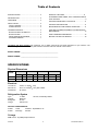
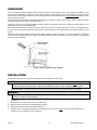
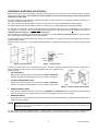
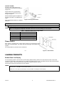
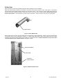
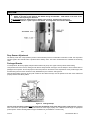
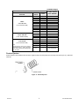
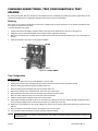
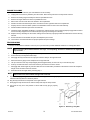
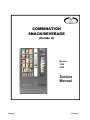
COMBINATION
SNACK/BEVERAGE
(Combo II)
Models:
3516
3534
Service
Manual
FEB 2008
P/N 4216441
Table of Contents
SPECIFICATIONS .................................................. 2
PRODUCT EJECTORS ................................................ 8
INTRODUCTION .................................................... 2
CHANGING AUGER TIMING, TRAY CONFIGURATION &
TRAY SPACING................................................................ 9
UNPACKING .......................................................... 3
COIN MECHANISM & BILL VALIDATOR ....................... 11
INSTALLATION ...................................................... 3
OUTLET TESTER ............................................... 5
POWER SWITCH ................................................ 5
CONTROLLER FUNCTIONS .......................................... 11
REFRIGERATION FUNCTIONS & OPERATION ........... 11
CARE AND CLEANING SCHEDULE FOR PREVENTIVE
MAINTENANCE .............................................................. 15
LOADING PRODUCTS .......................................... 5
BOTTLES/CANS LIVE DISPLAY ......................... 5
BOTTLES/CANS ................................................. 6
DROP SENSOR ADJUSTMENT ......................... 7
PACKAGED SNACKS ......................................... 7
PARTS ORDERING PROCEDURE ................................ 15
BEFORE CALLING FOR SERVICE ................................ 16
The Model and Serial numbers are needed for you to obtain quick service and parts information for your machine. The
numbers are given on the identification plate located on the back side of the cabinet of the machine.
MODEL NUMBER: ______________________________________________
SERIAL NUMBER: ______________________________________________
SPECIFICATIONS
Physical Dimensions
WIDTH
MODEL
DEPTH
HEIGHT
WEIGHT
Inches
Cm
Inches
Cm
Inches
Cm
Pounds
Kg
3516
42
106
34-3/8
87
72
183
963
437
3534
42
106
34-3/8
87
72
183
963
437
Electrical
115 Volt AC:
230 Volt AC:
Transformer:
60 Hz, 7.5 Amps ( 10%)
50 Hz, 3.75 Amps ( 10%), 862.5 Watts
24 Volt AC
Refrigeration System
Type:
Controls:
Refrigerant:
Charge:
3 - Wide
Electronic
R-134a
8.65 Ounces
1/3 Plus, Hermetically Sealed
FACTORY CONFIGURATION
3-Wide:
Snack
29 Select - Expandable to 42
3-Wide
Beverage
6 Select
Coinage
MDB version - any MDB peripheral device
Combo II
ii
P/N 4216441 REV A
INTRODUCTION
This manual contains service and installation guidelines and instructions for the Combination Snack/Beverage product line.
All Combination models are equipped with an electronic control system. All programming of the vend functions, pricing and
features is done at the controller. Changes can be made without any additional accessories or remote parts.
Selections can be priced individually from $.05 to $999.95 in five cent increments (U.S. currency).
Features include:
Multi Drop Bus (MDB) coin handling mechanism
Self-diagnostics and cash accountability
Multi Vend, Free Vend, Bonus Vend and Promo Vend features
Hermetically sealed refrigeration system with R-134a refrigerant
Programmable electronic control of the refrigeration unit
Motorized delivery, electronically controlled
CAUTION:
This vendor utilizes DC motors. Do not attempt to turn augers by hand. Motor damage could occur.
Visual feedback when a product has been vended or when an error condition exists
No change or loss of program/memory because of power failure
Cash accountability records Total Cash transactions and Total Vend cycles performed by the vendor. Information for individual
selections, complete range (rows) or total machine can be compiled and used for inventory and ordering records
The vending sequence is "first-in, first-out" for each selection, eliminating the need for stock rotation to maintain fresh products
in the vend area.
This manual should be read thoroughly to become familiar with the functions of all components, along with the features that are
available. The initial set-up of a vending machine is very important in insuring trouble-free operation of the equipment. Following
the instructions at the initial installation of the machine will avoid service problems and minimize set-up time.
Should you have any questions pertaining to information in the manual, replacement parts or the operation of the vendor you
should contact your local distributor or:
VendNet
165 North 10th Street
Waukee, Iowa 50263 - USA
Parts: (888) 259-9965
Service: (800) 833-4411
Parts Fax: 515-987-4447
All Other: (888) 836-3638
E-Mail: [email protected]
Combo II
2
P/N 4216441 REV A
UNPACKING
This vendor was thoroughly inspected before leaving the factory and the delivering carrier has accepted responsibility for this
vendor. Note any damage or irregularities at the time of delivery and report them to the carrier. Request a written inspection
report from the claims inspector to file any claim for damage. File the claim with the carrier (not the manufacturer) within 15 days
after receipt of the machine.
Carefully remove outside packing material to avoid damage to the finish or exterior of the machine. Remove adhesive residue
with denatured alcohol or common household vinegar.
Inspect the machine for concealed shipping damage. Report any damage hidden by the shipping material directly to the
delivering carrier on a hidden damage report.
Record the model number and serial number of the vendor for your records. These numbers can be found on the Serial Plate on
the rear of the cabinet and/or inside the vendor. Refer to these numbers on all correspondence and inquiries pertaining to this
vendor.
Remove the Knock-Away Skids by placing a block spacer under the vendor. See Figure 1. Insert a screwdriver or prying tool
into the groove and split the skid in two. Discard the slotted washers located on each side of the wooden skids. Turn the leveling
screws in as far as possible.
A10116
Figure 1. Removing Knock-Away- Supports
INSTALLATION
Consult local, state and country codes and regulations before installation of the vendor.
CAUTION:
To insure reliability and maintain manufacturers equipment warranty, machine must NOT be placed in an
environment where the temperature is greater than 90 F/32 C and the relative humidity is 65% or greater.
1.
Position the vendor in its place of operation no further than six (6) feet (2 m) from the power outlet or receptacle.
WARNING:
DO NOT USE EXTENSION CORDS.
Extension cords can cause problems.
2.
3.
4.
5.
6.
Leave at least six (6) inches (15 cm) of space between the back of the machine and any wall or obstruction for proper air
circulation.
Retrieve the keys to the vendor from the coin return cup.
Open outer door and remove all internal packing material.
Check that the door will open fully without interference.
Level the vendor, making sure all levelers are touching the floor. The vendor must be level for proper operation and
acceptance of coins through the coin mechanism.
Combo II
3
P/N 4216441 REV A
GROUNDING (EARTHING) & ELECTRICAL
Before connecting the vendor, the integrity of the main electrical supply must be checked for correct polarity, presence of ground
(earth) and correct voltage. These checks should be repeated at 6-month intervals with the routine safety electrical
testing of the vendor itself.
For proper operation of any equipment utilizing electronically controlled components, the equipment should be placed on an
isolated or dedicated noise-free circuit.
For 115-Volt vendors the circuit should be a minimum 15 Amp, 60 cycle, properly polarized and grounded (earthed).
For 230-Volt vendors the circuit should be a minimum 7.5 Amp, 50 cycle, properly polarized and grounded (earthed).
To verify that the receptacle is properly grounded (earthed) and polarized, insert one probe of a Multi-Meter (set to check AC
line voltage) or a test light in the ground (earth) terminal (hole) and the other probe into the hot terminal of the outlet. If
unfamiliar with this procedure, contact a licensed electrician.
If the receptacle is not properly grounded (earthed) or polarized, you should contact a licensed electrician to correctly polarize
and/or ground (earth) the receptacle to ensure safe operation.
A noise suppressor has been installed in this machine to compensate for any signal noise that could interfere with the normal
operation of the controller.
Shown in Figure 2 and Figure 3 are properly grounded (earthed) and polarized wall outlets. Figure 2 shows two 230-Volt wall
outlets.
Figure 2. 230-Volt Outlets
Figure 3. 115-Volt Outlet
Connect the vendor power cord to a grounded 115 Volt AC, 60 Cycle, noise free polarized power source of not less than 15
Amps. Checking the power source can be accomplished with an AC Voltmeter in the
following manner:
1.
VOLTAGE CHECK
When the AC Voltmeter probes are connected to the HOT and NEUTRAL
terminals, the voltmeter should indicate 110 to 130 volts AC. See Figure 4.
2.
POLARITY AND GROUND CHECK
When the AC Voltmeter probes are connected to the HOT and GROUND
terminals, the voltmeter should indicate 110 to 130 Volts AC. See Figure 4.
Figure 4. Electrical Check with Voltmeter
3.
NOISE POTENTIAL CHECK
When the AC Voltmeter probes are connected to the NEUTRAL and GROUND terminals, the voltmeter should indicate 0
Volts AC. See Figure 4. Any voltage reading could cause noise problems in the electronic controller.
4.
AMPERAGE CHECK
At the fuse box or circuit breaker panel, locate the proper circuit and ensure that the fuse or breaker protecting that circuit is
rated at 15 Amps or greater.
NOTE
In a standard three (3) prong 115 Volt AC wall outlet the GROUND pin is round, the NEUTRAL pin is rectangular and located
clock-wise from the ground pin and the HOT pin is rectangular and smaller than the neutral pin and located counterclockwise from
the ground pin. See Figure 4.
To correct negative voltage, amperage, polarity, or ground checks, consult a licensed electrician. To correct a negative noise
potential check, install a noise suppressor which can be obtained from any electrical or electronic supply store or in kit form.
Combo II
4
P/N 4216441 REV A
OUTLET TESTER
An easy to read outlet tester can be
obtained from any electrical or electronic
supply store.
Plug the tester into any grounded (3prong) 115V AC outlet to detect faulty
wiring. See Figure 5.
Read the indicator lights as explained on
the tester. See Table 1 for explanation of
faults.
Refer all indicated problems to a qualified
electrician.
A10593
Figure 5. 3-Prong Outlet Tester
CAUTION
Unplug all equipment on branch circuit before testing.
NOTE
This is not a comprehensive diagnostic instrument. Please refer to the tester packaging for more information.
Table 1. Indicated Problems when using a tester
FAULT
REASON FOR FAULT
Open Ground
Open Neutral
Open Hot
Hot Ground Reverse
Hot Neutral Reverse
Ground contact not connected
Neutral contact not connected
Hot contact not connected
Hot and ground contacts interchanged
Hot and neutral contacts interchanged
Power Switch
Each vendor is equipped with a power switch located on the transformer panel
along with a 3-Amp breaker. The switch will shut-off the light and controller. See
Figure 6.
The 3-Amp breaker is protection for the transformer.
Figure 6. Power Switch
A10674
LOADING PRODUCTS
Bottles/Cans Live Display
The Live Display provides a full view of the products being dispensed along with the price and selection number of each item.
To load the Live Display, simply slide the can or bottle into position from the rear. The black foam liner will hold the product
securely in position. Be sure that the product label faces outward toward the customer.
Turn the price scroll to the correct price for each selection.
NOTE
Facing the open machine, COLUMN 1 is the far right front column. COLUMN 2 is the far right back column. Column 5 is the far
left front column. COLUMN 6 is the far left back column.
Standard 12 oz cans may be double loaded in the front and back, increasing the column capacity.
Combo II
5
P/N 4216441 REV A
Bottles/Cans
Make sure that the product being loaded matches the product displayed in the Live Display.
Make sure that the white composite Funnel Slide on each side of each product column is clean. See Figure 9. This assures
that the product cannot bridge, blocking delivery from the product column. Then check the product cradle (“bed” area of the
delivery mechanism located at the bottom of the product column) to be sure that it is properly aligned with the bed area facedown in each column. If it is not facedown, cycle the motor to re-position. If this is not done, motor may jam. See Figure 7.
A10678
PRODUCT CRADLE
Figure 7. Delivery Mechanism
Most products (10 to 20 ounce cans and bottles) may be loaded without column adjustment. However, the front and back gates
to the product columns may be adjusted if necessary. To adjust column depth (front to back): with the gate closed, lift the gate
assembly (right and left sections together) and reposition in the adjustment slots. Product should have not more than 1/8 to
1/4 in. free space at front or back of column. See Figures 7 and 8.
FRONT GATE ASSEMBLY
BACK SPACER
LOCATION OF
PRODUCT CRADLE
Figure 8. Bottle/Can Product Area.
Combo II
6
P/N 4216441 REV A
CAUTION:
When loading bottled product, make sure that the bottoms of the bottles face the center of the machine. Load
bottles in the back of the machine with bottom facing the attendant. Load bottles in the front of the
machine with top facing the attendant.
Do not load dented or damaged cans or bottles in the columns. Possible jams could occur.
Do not store bottles in “spare” space of the cabinet. The refrigeration unit could be damaged.
Figure 9. Product Column (open)
Drop Sensor Adjustment
The delivery chute uses a drop (vibration) sensor to detect whether product is vended after a selection is made. The drop sensor
sends a signal to the controller when a product hits the delivery chute. The sensor is attached to the underside of the delivery
chute.
Packaged Snacks
To load products, lift the tray slightly and pull forward until the tray stops. The upper-most trays tilt for easier loading.
Load products from front to back, making sure all items fit freely between the augers. Do not attempt to force oversize items or
packages into the spaces. Do not skip a space. Place the product on the bottom of the compartment on the product augers, with
the label facing the front of the machine for easy identification by the customer. See Figure 10.
When finished loading each tray, lift and push it back into the cabinet. All trays must be pressed to the rear of the cabinet and
properly seated in the detent position.
A10114
Figure 10. Loading Example
The size of the item being vended must be larger than the diameter of the auger being used to vend properly. Undersize
items could cause vend problems. If the product does not fit the auger properly, use a different pitched auger or appropriate
product spacer. See the following table for augers available from your distributor or service entity.
Combo II
7
P/N 4216441 REV A
Available Augers
SELECTION
TYPE/COLUMN WIDTH/DIA &
ROTATION
CANDY
2-3/8” DIA CCW
(2-3/4” WIDE COLUMN)
SNACK (CRISPS)
2-25/32” DIA CCW
(4-5/16” WIDE COLUMN)
DUAL
2-3/8” DIA CW
(5-3/4” WIDE COLUMN)
Note:
Dual type selections require a pair of matching
2-3/8” diameter augers — CCW on the left and
CW on the right. Please select matching auger
from Candy type.
PRODUCT
SPACE
COUNT
COMBO AUGER
PART NUMBER
.5”
.7”
.9”
1.0”
1.2”
1.4”
1.7”
2.0”
2.3”
2.9”
3.8”
24
18
15
13
11
10
8
7
6
5
4
4211397.006309
4200272.112309
4211397.004309
4200272.116309
4211397.002309
4211397.003309
4211397.001309
4200272.122309
4211397.023309
4200272.123309
4211397.015309
1.2”
1.6”
1.9”
2.0”
11
9
8
7
4200272.114309
4200272.115309
4200272.119309
4211397.011309
.9”
1.4”
1.7”
2.0”
2.3”
15
10
8
7
6
4211398.004309
4211398.003309
4211398.001309
4211398.002309
4211398.013309
2.9”
5
4211398.023309
Product Ejectors
Product ejectors can be added to the end of the augers to help move the product out of the tray area (see Figure 11). Order P/N
4025748.
A10085
Figure 11. Product Ejectors
Combo II
8
P/N 4216441 REV A
CHANGING AUGER TIMING, TRAY CONFIGURATION & TRAY
SPACING
By re-timing the augers, difficult-to-vend items can be dispensed more consistently. By altering tray spacing, larger items can be
vended. By changing the tray configuration, different product mixes can be accommodated.
Retiming
Each auger can be rotated in 20-degree increments for a different drop-off point. Most items can be vended successfully when
the auger end is positioned at 6 o'clock.
To change the auger end position:
1.
Unsnap and lift the motor slightly and pull forward on the auger until it separates from the motor. See Figure 12.
2.
Rotate the auger to the desired position and re-insert the auger coupling into the motor.
3.
Make sure the splined auger coupling snaps into place and is seated over the vertical rail (see Figure 12) or retaining rib on
the tray.
4.
Gently pull forward on the auger to verify proper installation.
A10701
Figure 12—AUGER TIMING
Tray Configuration
Candy to Snack
1.
Order the conversion kit from your local distributor or service entity.
2.
Unplug and remove the tray assembly from the vendor. Place the tray harness in the tray before removal.
3.
Remove existing tray divider and store for possible future use.
4.
Remove existing auger assemblies and store for possible future use.
5.
Remove the existing "even" numbered motor. This motor will not be needed.
6.
Dress terminals removed from the motor around the tray harness and tape in place.
7.
Move the "odd" numbered motor to the center slot of the compartment.
8.
Install the auger retainer furnished as part of the conversion kit.
9.
Install auger assembly furnished as part of the conversion kit, making sure the motor coupling properly engages the motor
and is securely snapped over the vertical rail (see Figure 8) or retaining rib on the tray.
10. Replace the tray assembly into the vendor making sure that the tray is properly located and latched and connect the tray
harness
11. Set the selection to the desired vend price and adjust the price scroll to agree.
12. Test vend the converted selections for proper operation and price settings.
NOTE
Combo II
In large item selections, the selection numbers will be the "odd" numbers. For example, selections C3 and C4 are converted to a
single selection, C3.
9
P/N 4216441 REV A
SNACK TO CANDY
1.
Order the conversion kit from your local distributor or service entity.
2.
Unplug and remove the tray assembly from the vendor. Place the tray harness in the tray before removal.
3.
Remove the existing auger assembly and store for possible future use.
4.
Remove the auger retainer and store for possible future use.
5.
Move motor from the center slot to the left slot in the compartment.
6.
Add the new motor furnished as part of the conversion kit in the right hand slot of the compartment.
7.
Properly wire the motor and switch. (Refer to the Schematic section for wire colors and locations).
8.
Add the divider furnished as part of the conversion kit.
9.
Install new auger assemblies furnished in conversion kit, making sure the motor couplings properly engage with the motor
and are securely snapped over the vertical rail (see Figure 8) or retaining rib on the tray.
10. Replace the tray assembly into the vendor making sure that the tray is properly located and latched and connect the tray
harness.
11. Set the selections to the desired vend price and adjust the price scrolls.
12. Test vend the converted selections for proper operation and price settings.
TRAY SPACING
The trays can be raised or lowered in one-inch (2.5 cm) increments to provide additional headroom for vending taller items.
NOTE
1.
To change the vertical tray spacing, follow these steps:
2.
Pull out the tray to be adjusted until it stops.
3.
Disengage the tray harness from its snap-open harness clamp on the right-hand wall.
4.
Disconnect the tray plug from its receptacle on the right side wall.
5.
Lift up on the front of the tray and pull slightly forward (approximately 1/2 inch/1.25 cm) to clear the tray stop.
6.
Pull tray out until it tilts down. Lift the rear of the tray and remove it from the vendor.
7.
Disengage both left and right tray rails from their slots on the side walls: pull inward on the bottom of each rail and pull its
flanges out of the slots in the front and rear.
8.
Relocate both left and right rails by reversing step 7.
NOTE
9.
When increasing the headroom between two trays, a corresponding decrease in headroom of an adjoining
tray will result.
Rails must be level front to back and right side to left side.
Replace the tray by placing its rear rollers on the left and right rails and lifting up slightly on the front of the tray as you push
it back until the tray latches in its detent position.
10. Plug the tray harness into its receptacle on the right side wall.
11. Re-engage the tray harness into its harness clamp and snap the clamp closed.
12. Test vend the tray in its new position to assure that the tray plug is properly
seated.
A10111
Figure 13. Removing a Tray Rail
Combo II
10
P/N 4216441 REV A
COIN MECHANISM & BILL VALIDATOR
CAUTION:
Do not plug in or unplug the coin changer with the power on!
The controller will monitor the condition of the coin changer at all times. Any activity (coins inserted) will be recorded and stored
in the controller.
REMOVING ACCEPTED BILLS
Accepted bills may be removed by opening the “bill box” lid or by removing the bill box from the validator. (See manual from
validator manufacturer).
NOTE
If the bill box is removed, make sure that it is fully latched in place when it is returned to the validator.
CLEARING JAMS & CLEANING
Trapped bills, debris or dirt can result in poor bill acceptance or bill rejection. Remove the bill box and lower housing to clear
trapped bills or debris. Clean the bill path plastic parts or belts with a cloth moistened with a mild soap and water solution.
Clean the magnetic head and optic sensors using a swab and isopropyl alcohol. (See manual from validator manufacturer)
CAUTION:
Do not use any petroleum based cleaning solvents, scouring pads or stiff brushes for cleaning.
CONTROLLER FUNCTIONS
See accompanying programming manual for instructions concerning setting up your controller model.
REFRIGERATION FUNCTIONS & OPERATION
REFRIGERATION CONTROL
NOTE
To prevent damage to the refrigeration unit when it is turned off or the power interrupted, the refrigeration
unit will not restart for at least three minutes regardless of the temperature.
When the temperature is above the cut-in temperature programmed, the unit is turned on. When the refrigeration unit
reaches the cut-out temperature, it is turned off.
If the refrigeration unit runs for more than two hours without reaching the cut-out temperature, the unit is turned off for the
programmed ten (10) minute defrost time. It will then be turned on again automatically.
REFRIGERATION TROUBLESHOOTING
If the refrigeration unit is turned off or the power is interrupted, the refrigeration unit will not start for at least three minutes
regardless of the temperature. This is done to prevent damage to the refrigeration unit.
CAUTION:
Breaking the refrigerant joints or seals on the system voids the unit warranty. Failure to keep the condenser
coil clean and free of dirt and dust and other similar debris voids the unit warranty.
Know and understand how the unit operates. Units may vary, but the operation is basically the same. Never guess at the
problem; find the symptom before attempting any repair.
NOTE
Combo II
Most refrigeration problems are electrical.
11
P/N 4216441 REV A
The sealed hermetic system should not be worked on outside the Factory Service Center. There are three things that
can go wrong with a sealed system and should be repaired only at the Factory Service Center. These are:
Low Charge - usually caused by leaks; look for oil around seals and welds. Unit will not cool properly. The capillary tube
is frosted before it enters the evaporator inlet tube.
Restriction in Systems (unit frosts, then melts) - not cooling properly
Bad valves - unit does not cool properly-- noisy compressor
COMPRESSOR WILL NOT START
Compressor has no power
Machine not plugged in
Tripped breaker or blown fuse
Faulty wall outlet
Short or open in power cord
Temperature sensor circuit is open (check with a Multi-Meter)
Improper wiring
Low voltage: 5% below (check the power source with a Multi-Meter)
Overload defective: Trips too fast (check overload with the Multi-Meter)
Start relay defective (check start relay with the Multi-Meter)
Compressor has open windings (check compressor windings with a Multi-Meter)
Defective refrigeration relay
o Unplug power to the machine; remove the relay plate. Use an insulated jumper wire to short the wires on relay
terminals 2 and 4 or 6 and 8-- then restore power to the machine. The compressor should start, indicating a problem in
the control circuit.
o Check relay terminals 1 to 0 with a Multi-Meter. Should have 24VDC applied to them.
o No DC voltage (check control board output terminal for a loose connection)
COMPRESSOR TRIPS ON OVERLOAD
Improper voltage: 5-10% above, 5% below (check power source with Multi-Meter)
Overload defective: Trips too fast (check overload with Multi-Meter)
Relay defective: Won’t open after starting (check relay with Multi-Meter)
Compressor has shorted windings (check compressor windings with Multi-Meter)
Short in other component: Isolate and eliminate each electrical component until short is found
Compressor is too hot
o Dirty condenser
o Faulty condenser motor or blade
o Restricted airflow
CAUTION:
Condenser must be kept clean of dirt and debris to allow for proper air circulation.
NOISY OR VIBRATING UNIT
Components rubbing or touching each other
o Check fan blades and motor
o Loose shrouds and harness
o Copper tubing
o Loose or unsecured parts
o Dirty condenser fan blades
Worn or aged compressor grommets
Compressor
o Bad valves
Combo II
12
P/N 4216441 REV A
o Slugging
o Bad windings (See Schematic)
o Low voltage
UNIT SHORT CYCLES
Temperature sensor defective or not mounted in the return air duct
Defective control board
Temperature setting set too warm (see “Refrigeration Settings” section of this manual)
UNIT OPERATES LONG OR CONTINUOUSLY
Temperature sensor defective or not mounted in the return air duct
Refrigeration relay shorted
Air flow restricted
o Faulty evaporator motor or blades causing coils to ice
o Loose connections on evaporator motor (1 motor not running.)
o Airflow blocked by product in front of evaporator or air duct openings
o Exhaust area blocked (machine too close to wall)
Gasket leak around door
Excessive load: After loading, unit runs longer to pull out excessive heat from product
Shortage of refrigerant or restriction
Bad controller
Ambient air temperature and relative humidity exceed manufacturer’s operational standards
REFRIGERATED SPACE TOO COLD
Temperature sensor defective (check with Multi-Meter)
Refrigeration control setting too cold (see “Refrigeration Settings” section of this manual)
Refrigeration relay bad (check with Multi-Meter)
Faulty control board
REFRIGERATED SPACE TOO WARM
Temperature sensor defective (check with Multi-Meter)
Refrigeration control setting too warm (see “Refrigeration Settings” section of this manual)
Refrigeration relay bad
Faulty control board
Restricted evaporator space
Evaporator motor or blades faulty, causing the coils to ice over the evaporator
Condenser air flow restricted
Plugged or dirty condenser
Condenser motor or blades bad
Blade stuck
Condensing space restricted
Unit placed too close to a wall
Compressor - bad valves
Capillary tube will start frosting 8 to 10 inches (20-25 cm) past evaporator connection tube
Check for oil around brazed connections
Combo II
13
P/N 4216441 REV A
TROUBLESHOOTING CIRCUITS WITH MULTI-METER
To check the power source, use the voltage section of the Multi-Meter (should measure within 5-10% above, 5% below)
Check overload
CAUTION
Power must be off and fan circuit open.
Using the resistance section of the Multi-Meter, check terminals 1 and 3 for continuity. If no continuity is measured (infinity),
overload may be tripped. Wait 10 minutes and try again. If still no continuity, overload is defective.
Check relay (See Figure 15.) Unscrew lead terminals and remove relay from compressor. (NOTE: keep relay upright)
Check terminals 1 and S, or L and S with the Multi-Meter. Replace relay if continuity exists.
Check Temperature sensor with a Multi-Meter.
Check compressor windings as shown in Figure 15.
Check winding resistance with a Multi-Meter. If readings are not within 2 Ohms, the compressor is faulty. Use RX1 scale.
WARNING:
Wiring diagrams must be followed as shown. Any mis-wiring can cause serious electrical hazard and potential
damage or rupture component electrical parts.
Winding Resistance
APPROX. RESISTANCE ACROSS TERMINALS
COMMON to START:
12 Ohms
COMMON to RUN:
2 Ohms
RUN to START:
14 Ohms
COMMON to SHELL:
No Continuity
A10115
Figure 15. Compressor Schematic
Combo II
14
P/N 4216441 REV A
CARE AND CLEANING SCHEDULE FOR PREVENTIVE MAINTENANCE
Once a Month
CAUTION:
Always disconnect power source BEFORE cleaning or servicing.
CLEAN CABINET INTERIOR:
Wash with a cleaning solution of mild detergent and water, rinse and dry thoroughly. Odors may be eliminated by including
baking soda or ammonia in the cleaning solution. Plastic parts may be cleaned with a quality plastic cleaner. Keep delivery slide
area free of dirt and sticky substances. Remove and clean condensate drain hose to eliminate any deposits that may restrict
condensate water flow.
Do not get the cleaning solution on electrical components.
Snack Compartment: The vend mechanisms and trays must be wiped clean of dirt and sticky substances. Any build-up can
cause the mechanisms to malfunction.
Can/Bottle Compartment: The can/bottle racks must be wiped clean of dirt and sticky substances.
CLEAN CABINET EXTERIOR:
Wash with a mild detergent and water, rinse and dry thoroughly. Clean occasionally with a quality car wax. Plastic exterior parts
may be cleaned with a quality plastic cleaner.
Every 60-days
CLEAN REFRIGERATION INTAKE SCREEN:
Remove screen and clean dust and debris from screen using a soft bristle brush or a vacuum cleaner.
Every 6-months
CLEAN THE CONDENSER COIL AND REAR EXHAUST SCREEN:
Remove the Cover Assembly and clean the condenser coil of refrigeration unit using a soft bristle brush and/or vacuum cleaner.
Pull the refrigeration unit and clean the rear exhaust screen of dirt and debris.
Do not block the evaporator or any area of the airflow with product or supplies.
PARTS ORDERING PROCEDURE
When ordering parts, include the following:
1.
The model and serial numbers of the machine for which the parts are needed.
2.
Shipping address
3.
Address where the invoice should be sent.
4.
The number of parts required.
5.
Always refer to the pertinent parts and/or part manual for the correct part number and description of a specific part
NOTE
When RIGHT or LEFT is used with the name of a part, it is means the person is facing the machine with the door closed.
6.
Any special shipping instructions.
7.
Carrier desired: air or air special, truck, parcel post or rail.
8.
Signature and date.
9.
Purchase order number, if used.
Mail your order to:
VendNet™
P. O. Box 488
165 North 10th Street
Waukee, IA 50263-0488 USA
All orders are carefully packed and inspected prior to shipment. Damage incurred during shipment should be reported at once
and a claim filed with the terminating carrier.
Combo II
15
P/N 4216441 REV A
If you do not have the right parts manual: contact VendNet™.
If you have any questions, check out our Website www.vendnetusa.com or call VendNet . Ask for the Parts Department. We
will be happy to assist you. Email: [email protected]
BEFORE CALLING FOR SERVICE
Please check the following
Does your machine have at least 6-inches of clear air space behind it?
If the power is turned on at the fuse box, is the machine the only thing that doesn’t work?
Is the machine plugged directly into the outlet?
WARNING:
Extension cords can cause problems.
DO NOT USE EXTENSION CORDS.
Is the evaporator coil free of dust and dirt?
Is the condenser coil free of dust and dirt?
Is the compressor free of dust? (A blanket of dust can prevent the compressor from cooling in between workouts).
Is the circuit breaker at the fuse box reset?
Are evaporator fans running? To check if fans are running take a small piece of paper in front of the evaporator coil and see
if the evaporator fans will blow the paper away.
Is the condenser fan running? Fold a sheet of 8 1/2” x 11” paper in half. Place the paper in front of the condenser coils and
see if it draws the paper to it.
Is the shelf in front of the evaporator coil clear? (No tools, product, or other air-restricting items).
Is the cold control set as specified?
NOTE
Setting the temperature colder does not accelerate cooling of product.
The contents of this publication are presented for informational purposes only, and while every effort has been made to ensure their accuracy, they are not to be construed
as warranties or guarantees, express or implied, regarding the products or services described herein or their use or applicabillity. We reserve the right to modify or improve
the designs or specifications of such products at any time without notice.
VendNet™
165 North 10th Street
Waukee, Iowa 50263
United States of America
Service
USA & Canada
Parts
(800) 833-4411
Email
(888) 259-9965
Web Site
International
(515) 274-3641
[email protected]
Web Site
4216441 COMBO SERVICE MANUAL GVC
Combo II
16
P/N 4216441 REV A