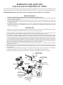
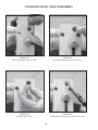
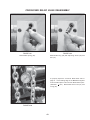
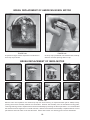
1
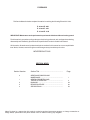
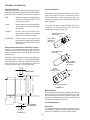
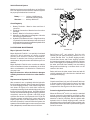
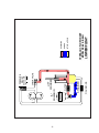
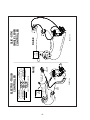
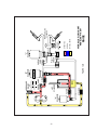
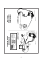
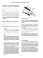
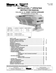
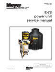
FORM NO. 1-562-R16
October, 2005
Price: $4.25
ELECTRO LIFT®
power units
service manual
MODELS
E-46, E-46H
E-47, E-47H
E-57, E-57H
Meyer Products Inc.
18513 Euclid Ave. • Cleveland, OH 44112-1084
Phone (216) 486-1313
email•[email protected]
© 2005 Printed in the U.S.A.
Diamond Equipment
6 Angell Lane• Damariscotta, ME 04543-9720
Phone (207) 563-2227
www.diamondplow.com • email [email protected]
FOREWARD
This Service Manual includes complete information for servicing the following Electro Lift® Units:
E - 46 and E - 46H
E - 47 and E - 47H
E - 57 and E - 57H
IMPORTANT: Maintenance and repairs must be performed with the moldboard on the ground.
The information is grouped according to the type of work being performed, such as diagnosis and testing,
disassembly and reassembly. Special tools and specifications are also included in this manual.
All information, illustrations and product descriptions contained in this manual are correct at publication
time. We do, however, reserve the right to make changes at any time without prior notice.
MEYER PRODUCTS INC.
SECTION INDEX
Section Number
Section Title .....................................................
0
GENERAL INFORMATION AND
MAINTENANCE ........................................................
GENERAL DESCRIPTION AND
THEORY OF OPERATION ........................................
DIAGNOSIS .............................................................
REPAIR PROCEDURE ..............................................
SPECIFICATIONS .....................................................
1
2
3
4
Page
1
4
23
30
53
Meyer Products Inc. reserves the right, under its continuing product improvement program, to change construction or
design details, specifications and prices without notice or without incurring any obligation.
SECTION 0
- GENERAL INFORMATION AND MAINTENANCE
CONTENTS
GENERAL INFORMATION ..................................................
2
•
MODEL IDENTIFICATION ....................................................
2
•
MODEL IDENTIFICATION AND
SERIAL NUMBER LOCATION ..............................................
2
•
MOTOR IDENTIFICATION ...................................................
2
MAINTENANCE ...................................................................
2
•
GENERAL MAINTENANCE ...................................................
2
•
CLEANLINESS .................................................................
2
•
VEHICLE ELECTRICAL SYSTEM ...........................................
3
•
CHECK REGULARLY .........................................................
3
POST-SEASON MAINTENANCE .......................................
3
•
MEYER HYDRAULIC FLUID M-1 .........................................
3
•
REPLACEMENT OF HYDRAULIC FLUID ...................................
3
•
FILTERS ........................................................................
3
PROTECTION AGAINST RUST
CORROSION ............................................................
3
•
AND
-1-
GENERAL INFORMATION
Model Identification
The Electro Lift® unit is an electrically powered hydraulic
mechanism specifically designed for use with the Meyer
Snow Plow and is available in four models as follows:
E-46
Raises and lowers plow hydraulically
(2-way) and is used with TM, ST and
C series Snow Plows.
E-46H
Raises and lowers plow hydraulically
(2-way) and is used with HM series
Snow Plows.
E-47/E-57
Raises, lowers and angles plow
hydraulically (7-way) and is used with
TM, ST and C series Snow Plows.
E-47H/E-57H
Motor Identification
Three different brand motors are used on the Electro
Lift® units American Bosch, Prestolite and Iskra.
Proper identification of the brand and supplier part
number is necessary when seeking local parts and
service sources.
The motor with which a specific Electro Lift® unit is
equipped can be identified by the distinctive
characteristics shown in figure 0-2.
DOMED COMMUTATOR
END COVER
3" Dia.
Raises, lowers and angles plow
hydraulically (7-way) and is used with
the MDII, HM and Diamond series
Snow Plows.
STEEL STAMPED
PRESTOLITE
MKW-4007-12V
E
LIT
TO
ES
PR
Model Identification and Serial Number Location
Inclusion of the model number and serial number is
extremely important when writing up warranty claim
forms and product report forms for proper evaluation
and follow up.
FLAT COMMUTATOR
END COVER
3" Dia.
The basic model number is located on the name plate
located as shown in Figure 0-1. To determine whether
it is the standard or “H” model, measure the dimension
shown in Figure 0-1. The serial number is located on
the bottom of the base or on the name plate.
STEEL STAMPED
AMERICAN BOSCH
MO 551046A
ISKRA
Label 15829
AMJ4739 12V 1,6kw
xxxxx
6-1/4"
FIGURE 0-2
MAINTENANCE
The following maintenance information is intended as
a basic guide for providing the Electro Lift® unit with
the proper service and care. Sustained heavy duty
operation or operating under adverse conditions may
necessitate more frequent servicing.
General Maintenance
SERIAL NUMBER
(ON FRONT SIDE)
Cleanliness
The greatest enemy to any hydraulic system is dirt or
contamination. Therefore, cleanliness must be stressed
at the time of installation, servicing and repairing.
FRONT VIEW
FIGURE 0 -1
4-1/2" Dia.
SINGLE and TWO TERMINAL
E-46, E-47, E-57
E-46H, E-47H, E-57H 8-1/8"
NAME PLATE
-2-
Vehicle Electrical System
Maximum performance and efficiency of the Electro
Lift® unit requires that the vehicle’s electrical system
be properly maintained and consist of:
Battery ----------Alternator ------
FILLER PLUG
LIFT ROD
70 Amp. Hr. Minimum or
550 Cold Cranking Amps.
60 Amp. Minimum
Check Regularly
1. Battery Terminals - Must be clean and free of
corrosion.
2. Electrical Connections - Must be free of corrosion
and tight.
3. Battery - Must be in first-class condition.
4. Alternator (or Generator) and Regulator - Must be
functioning to specifications.
5. Hydraulic Fluid Reservoir Level - A significant drop
in hydraulic fluid level indicates a leak which must
be located and corrected. Insufficient hydraulic fluid
may result in severe damage.
DRAIN PLUG
DR
AI
N
FILTERS
POST-SEASON MAINTENANCE
FIGURE 0-3
Meyer Hydraulic Fluid M-1.
Meyer Hydraulic Fluid M-1 is a specially formulated
mineral oil which maintains an almost constant
viscosity from normal to sub-zero temperatures.
Because it remains free flowing at extremely low
temperatures, the performance and efficiency are not
affected.
Refill Electro Lift ® unit with M-1 Fluid by fully
retracting lift rod (Ram) and filling reservoir to 1-1/2
“ below the filler hole. On Power Angling models,
fill and bleed hoses and Power Angling cylinders
by loosening hydraulic fittings at cylinders until they
leak. Power angle plow repeatedly from one side to
the other until fluid flows steadily from the leaking
fittings while maintaining a constant check on the
reservoir fluid level.
Meyer Hydraulic Fluid M-1 also contains an additive
which neutralizes moisture accumulating in the fluid
due to condensation. It is effective for a maximum of
one year’s use.
Raise and lower the plow several times and with lift
rod fully retracted, give a final check to the fluid level
and replace filler plug.
Meyer Products Inc. will not be liable for damages
resulting from the use of inferior or other fluids or
oils.
Filters
Replacement of Hydraulic Fluid
Clean the two filters (only one in E-46 and E-46H; two
in Power Angling units) located in base of unit with
mineral spirits or equivalent and blow out with
compressed air. See Figure 0-3 for filter locations.
After a season’s use, completely drain the hydraulic
fluid (including hydraulic fluid in hoses and cylinders
on Power Angling models). Drain fluid through filler
hole shown in Figure 0-3 or drain hole in base by
completely retracting lift rod and unbolting unit to pour
fluid out or using a suction pump. On Power Angling
models, disconnect the fittings at the Angling cylinders,
completely retract the cylinder rods and purge
cylinders and hoses of all hydraulic fluid. Flush the
complete system including unit, hoses and Power
Angling rams with a non wax (Napthenic) cleaner. If
kerosene (Parrafinic) is used to flush the system, the
system must be flushed again to remove any kerosene
with a (Napthenic) based cleaner that is wax free .
Protection Against Rust and Corrosion
When the Electro Lift® unit is not used for extended
periods, protect the chromed lift rod (Ram) by fully
extending it and coating it with chassis lubricant. Full
extension of the lift rod (Ram) fills the cylinder with
hydraulic fluid. On Power Angling models, coat the
exposed portions of the Power Angling cylinder rods
(Rams) with chassis lubricant to protect them against
rust and corrosion.
-3-
SECTION 1
- GENERAL DESCRIPTION AND THEORY OF OPERATION
CONTENTS
GENERAL DESCRIPTION .................................................................................................
5
THEORY OF OPERATION .................................................................................................
5
FUNCTIONS ..................................................................................................................
5
•• Models E-46 and E-46H ...................................................................................
5
•• Models E-47, E-47H and E-57, E-57H ...........................................................
5
•
•
ELECTRICAL AND FLOW CHARTS ...................................................................................... 6-18
ELECTRO LIFT® UNIT COMPONENTS .........................................................................
•
19
MOTORS ......................................................................................................................
19
•• American Bosch ...............................................................................................
19
•• Prestolite ............................................................................................................
19
•• Iskra ....................................................................................................................
19
•
HYDRAULIC PUMP ..........................................................................................................
19
•
PRESSURE RELIEF VALVE ................................................................................................ 19-20
•
SOLENOID VALVES .........................................................................................................
20
•• Cartridge ............................................................................................................
20
•• Coil ......................................................................................................................
20
“A” Solenoid Valve .............................................................................................
20
“B” Solenoid Valve ............................................................................................
20
“C” Solenoid Valve ...........................................................................................
20
•
CHECK VALVES ..............................................................................................................
21
•
PILOT CHECK VALVE ......................................................................................................
21
•
CROSSOVER RELIEF VALVES ............................................................................................
21
•
SWITCH (MODELS E-46
E-46H) ............................................................................
21
•
SWITCHES (POWER ANGLING MODELS) ............................................................................
21
AND
•• Dual Switch Control ........................................................................................... 21-22
•• Single Lever Control ..........................................................................................
22
•• Electro-Touch Control .........................................................................................
22
•
SOLENOID SWITCH ........................................................................................................
22
•
FILTERS .......................................................................................................................
22
-4-
GENERAL DESCRIPTION
THEORY OF OPERATION
Electro Lift ® unit is an electrically powered and
electrically controlled hydraulic mechanism specifically
designed for use with Meyer Snow Plows. The standard
model E-46 raises and lowers the plow hydraulically
with an integral 6" stroke hydraulic cylinder while the
model E-46H performs the identical task for larger plows
with an integral 8" stroke hydraulic cylinder.
FUNCTIONS
The Electro Lift® models perform basic functions.
Because certain of these basic functions are
accomplished differently in the models E-46 and
E-46H as opposed to the Power Angling models will
be treated separately where necessary.
Models E-46 and E-46H
In addition to raising and lowering the plow
hydraulically, the model E-47, E-47H and
E-57, E-57H angles the plow hydraulically, left and
right, via remote hydraulic cylinders.
The two basic functions performed are:
• Raise snow plow
• Lower snow plow and float
Refer to Figures 1-1 and 1-2 (pages 6 thru 9) for
electrical and hydraulic flow chart for each function.
Each figure explains which component is actuated and
related in each function.
The Electro Lift® unit consists of a specially designed
high torque 12-volt DC motor which is directly coupled
to a gear-type hydraulic pump. The pump obtains its
supply of hydraulic fluid from an integral reservoir which
totally surrounds the integral hydraulic cylinder which
raises and lowers the plow.
Models E-47, E-47H and E-57, E-57H
The four basic functions performed are:
• Raise snow plow
• Lower snow plow
• Angle snow plow to right
• Angle snow plow to left
Included in all models is an electrically controlled and
powered solenoid valve cartridge “A” which is
energized to allow the plow to lower by gravity.
The models E-47 and E-57 include an integral valve
body which contains two additional electrically
controlled solenoid valve cartridges. Solenoid valve
cartridge “B” is energized to route the pressurized
hydraulic fluid to the integral hydraulic cylinder to raise
the plow. Solenoid valve cartridge “C” is energized to
route the pressurized hydraulic fluid to the left remote
hydraulic cylinder to angle the plow to the right. Angling
the plow to the left only requires energizing the electric
motor since the normal route for the pressurized
hydraulic fluid is to the right remote hydraulic cylinder.
Refer to Figures 1-3 through 1-6 (pages 6 thru 18) for
electrical and hydraulic flow chart for each function.
Each figure explains which component is actuated and
related in each function.
Additional components which control and supply
electrical current to the Electro Lift® unit are an operator
controlled toggle switch; a solenoid switch to supply
high amperage current to the unit’s motor; a wiring
harness to distribute low amperage current between
the toggle switch or switches, motor solenoid and the
solenoid valve cartridge(s); and short heavy gauge
cables to distribute high amperage current directly from
the positive terminal of the vehicle’s battery and ground
the unit directly to the negative terminal of the vehicle’s
battery.
-5-
-6-
BLACK
A
FUSE
SOLENOID
SWITCH
BLACK
WHITE
MOTOR
SWITCH
RAISE &
LOWER
-
FIGURE 1-1A
RAISE
BATTERY
+
IGNITION
SWITCH
-7-
FIGURE 1-1B
STRAINER
FILTER
"A"
SOLENOID
TANK
LIFT
CYLINDER
CHECK VALVE
E-46 & E-46H
1650 + 50 P.S.I.
PRESSURE
RELIEF
RAISE
HYDRAULIC FLOW CHART
MODELS E-46 & E-46H
- INTAKE or DRAIN
- RETURN
- OPERATING
-8-
BLACK
A
FUSE
SOLENOID
SWITCH
BLACK
WHITE
MOTOR
SWITCH
RAISE &
LOWER
-
FIGURE 1-2A
LOWER/FLOAT
BATTERY
+
IGNITION
SWITCH
-9-
FILTER
FIGURE 1-2B
STRAINER
ENERGIZED
TANK
LIFT
CYLINDER
"A"
SOLENOID
CHECK VALVE
E-46 & E-46H
1650 + 50 P.S.I.
PRESSURE
RELIEF
LOWER/FLOAT
HYDRAULIC FLOW CHART
MODELS E-46 & E-46H
- INTAKE or DRAIN
- RETURN
- OPERATING
NE
G
POWER
WHITE
WIRE
SWITCH GROUND
ORANGE WIRE
Ignition Switch
"ON"
FUSE
PANEL
GROUND
BA
TT
ER
Y
PO
S
1
4
3 6
2 5
FIGURE 1-3A
A2
POSITVE
RED
DR
AIN
"B"
D1
NEGATIVE
ON / OFF
SWITCH
RAISE
(WHITE WIRE)
GROUND
(ORANGE WIRE)
POWER TO SWITCH
(BLUE WIRE)
TO MOTOR SOLENOID
POWER TO SWITCH
BLUE WIRE
A
END OF TOUCH PAD HARNESS
TO "A" SOLENOID
(BLACK WIRE)
TO "C" SOLENOID
(GREEN WIRE)
TO "B" SOLENOID
(RED WIRE)
ELECTRO -TOUCH
CONTROLLER
10
-10G E N U IN E
Meyer
C-H
P A R T S
10
Ignition Switch
"ON"
FUSE
PANEL
Red
wire
"B
" So
leno
id
ERG
IZED
A2
POSITVE
.
DR
AIN
"B"
D1
NEGATIVE
FIGURE 1-3A
is EN
WHITE WIRE - ENERGIZED
Motor Solenoid
RAISE
SLIK - STIK
SINGLE LEVER
CONTROLLER
-11STRAINER
FILTER
"A"
SOLENOID
TANK
LIFT
CYLINDER
POWER ANGLING
CYLINDERS
RAISE
HYDRAULIC FLOW CHART
MODELS E-47 & E-57
- INTAKE or DRAIN
- RETURN
- OPERATING
CROSSOVER
RELIEF
3800 + 400 P.S.I
"C"
SOLENOID
PILOT
CHECK
CHECK
VALVE
FIGURE 1-3B
ENERGIZED
"B"
SOLENOID
FILTER
CHECK VALVE
E-47
1650 + 50 P.S.I.
E-57
2000 + 0 P.S.I.
PRESSURE
RELIEF
S
NE
G
POWER
4
(WHITE WIRE)
BLACK
Black Wire "A" Solenoid
D1
NEGATIVE
A2
POSITVE
ON / OFF
SWITCH
LOWER/FLOAT
POWER TO SWITCH
BLUE WIRE
FIGURE 1-4A
WHITE
WIRE
SWITCH GROUND
ORANGE WIRE
Ignition Switch
"ON"
FUSE
PANEL
GROUND
BA
TT
ER
Y
PO
1
3 6
2 5
GROUND
(ORANGE WIRE)
POWER TO SWITCH
(BLUE WIRE)
TO MOTOR SOLENOID
END OF TOUCH PAD HARNESS
TO "A" SOLENOID
(BLACK WIRE)
TO "C" SOLENOID
(GREEN WIRE)
TO "B" SOLENOID
(RED WIRE)
ELECTRO -TOUCH
CONTROLLER
10
A
-12Bla
ck
G E N U IN E
Meyer
C-H
wir
e
P A R T S
10
"A"
S
Ignition Switch
"ON"
ole
no
id i
s
EN
ER
FIGURE 1-4A
GIZ
ED
.
Black wire "A" Solenoid
LOWER/FLOAT
SLIK - STIK
SINGLE LEVER
CONTROLLER
-13FILTER
STRAINER
ENERGIZED
"A"
SOLENOID
TANK
LIFT
CYLINDER
POWER ANGLING
CYLINDERS
LOWER/FLOAT
HYDRAULIC FLOW CHART
MODELS E-47 & E-57
- INTAKE or DRAIN
- RETURN
- OPERATING
CROSSOVER
RELIEF
3800 + 400 P.S.I
"C"
SOLENOID
PILOT
CHECK
CHECK
VALVE
FIGURE 1-4B
"B"
SOLENOID
FILTER
CHECK VALVE
E-47
1650 + 50 P.S.I.
E-57
2000 + 0 P.S.I.
PRESSURE
RELIEF
Y
G
WHITE
WIRE
SWITCH GROUND
ORANGE WIRE
Ignition Switch
"ON"
FUSE
PANEL
GROUND
ER
NE
POWER
BA
TT
PO
S
1
4
3 6
2 5
(WHITE WIRE)
GROUND
(ORANGE WIRE)
POWER TO SWITCH
(BLUE WIRE)
TO MOTOR SOLENOID
FIGURE 1-5A
A2
POSITVE
GREEN
DR
AIN
ON / OFF
SWITCH
"B"
D1
NEGATIVE
POWER TO SWITCH
BLUE WIRE
RIGHT ANGLE
END OF TOUCH PAD HARNESS
TO "A" SOLENOID
(BLACK WIRE)
TO "C" SOLENOID
(GREEN WIRE)
TO "B" SOLENOID
(RED WIRE)
ELECTRO -TOUCH
CONTROLLER
10
A
-14G E N U IN E
Meyer
C-H
10
P A R T S
Ignition Switch
"ON"
FUSE
PANEL
G re
en
wir
e "C
" So
EN
ERG
IZE
D
.
DR
AIN
D1
NEGATIVE
FIGURE 1-5A
len
oid
is
A2
POSITVE
WHITE WIRE - ENERGIZED
Motor Solenoid
RIGHT ANGLE
"C"
SLIK - STIK
SINGLE LEVER
CONTROLLER
-15-
STRAINER
FILTER
"A"
SOLENOID
LIFT
CYLINDER
TANK
"B"
SOLENOID
ENERGIZED
POWER ANGLING
CYLINDERS
ANGLE RIGHT
HYDRAULIC FLOW CHART
MODELS E-47 & E-57
- INTAKE or DRAIN
- RETURN
- OPERATING
CROSSOVER
RELIEF
3800 + 400 P.S.I
"C"
SOLENOID
PILOT
CHECK
CHECK
VALVE
FIGURE 1-5B
NOT
ENERGIZED
FILTER
CHECK VALVE
E-47
1650 + 50 P.S.I.
E-57
2000 + 0 P.S.I.
PRESSURE
RELIEF
Y
G
WHITE
WIRE
SWITCH GROUND
ORANGE WIRE
Ignition Switch
"ON"
FUSE
PANEL
GROUND
ER
NE
POWER
BA
TT
PO
S
1
4
3 6
2 5
(WHITE WIRE)
GROUND
(ORANGE WIRE)
POWER TO SWITCH
(BLUE WIRE)
TO MOTOR SOLENOID
FIGURE 1-6A
A2
POSITVE
DR
AIN
ON / OFF
SWITCH
"B"
D1
NEGATIVE
POWER TO SWITCH
BLUE WIRE
LEFT ANGLE
END OF TOUCH PAD HARNESS
TO "A" SOLENOID
(BLACK WIRE)
TO "C" SOLENOID
(GREEN WIRE)
TO "B" SOLENOID
(RED WIRE)
ELECTRO -TOUCH
CONTROLLER
10
A
-16G E N U IN E
Meyer
C-H
10
P A R T S
Ignition Switch
"ON"
FUSE
PANEL
DR
AIN
D1
NEGATIVE
FIGURE 1-6A
A2
POSITVE
WHITE WIRE - ENERGIZED
Motor Solenoid
LEFT ANGLE
"C"
SLIK - STIK
SINGLE LEVER
CONTROLLER
-17STRAINER
FILTER
"A"
SOLENOID
LIFT
CYLINDER
TANK
NOT
ENERGIZED
"C"
SOLENOID
PILOT
CHECK
CHECK
VALVE
FIGURE 1-6B
NOT
ENERGIZED
"B"
SOLENOID
FILTER
CHECK VALVE
E-47
1650 + 50 P.S.I.
E-57
2000 + 0 P.S.I.
PRESSURE
RELIEF
ANGLE LEFT
HYDRAULIC FLOW CHART
MODELS E-47 & E-57
- INTAKE or DRAIN
- RETURN
- OPERATING
CROSSOVER
RELIEF
3800 + 400 P.S.I
POWER ANGLING
CYLINDERS
-18-
BLACK
RAISE
&
LOWER
SWITCH
BLACK
RAISE
&
LOWER
SWITCH
RED
A
B
B
BLACK
WHITE
WHITE
A
RED
WHITE
BLACK
WHITE
MOTOR
C
GREEN
MOTOR
BLACK
SWITCH ANGLE
WHITE
C
GREEN
BLACK
SWITCH ANGLE
WHITE
-
-
BATTERY
+
IGNITION
SWITCH
RAISE
BATTERY
+
BLACK
RAISE
&
LOWER
SWITCH
BLACK
RAISE
&
LOWER
SWITCH
A
RED
B
BLACK
WHITE
WHITE
A
RED
B
BLACK
WHITE
DUAL SWITCH WIRING
ANGLE LEFT
SOLENOID
SWITCH
FUSE
SOLENOID
SWITCH
FUSE
IGNITION
SWITCH
WHITE
MOTOR
C
GREEN
MOTOR
BLACK
SWITCH ANGLE
WHITE
C
GREEN
BLACK
SWITCH ANGLE
WHITE
BATTERY
+
BATTERY
+
ANGLE RIGHT
SOLENOID
SWITCH
FUSE
IGNITION
SWITCH
LOWER/FLOAT
SOLENOID
SWITCH
FUSE
IGNITION
SWITCH
ELECTRO LIFT® UNIT COMPONENTS
ELECTRO LIFT UNIT COMPONENTS
®
MOTORS ( 3”) E-46, E-46H and E-47, E-47H
The 12-volt DC high torque motor used on the Electro
Lift® units are interchangeable among all four models.
Its function in all four applications is to drive the
hydraulic pump. The motor is only energized and
operating when pressurized hydraulic fluid is required.
RESERVOIR
Two different brand motors were used. While they are
interchangeable and have nearly identical performance
characteristics, they have distinctive design differences.
ELECTRIC
MOTOR
W
O
FL
American Bosch
INTAKE LINE
The American Bosch motor is a four pole, permanent
magnet motor which consists primarily of a 3" diameter
solid steel frame, armature, brushes and ceramic
permanent magnet fields. Because the fields are
permanent magnets, they do not require electrical
current to operate. Therefore, the motor requires lower
amperage to produce a given amount of power.
DRIVEN GEAR
W
O
FL
PUMP CHAMBER
OUTLET LINE
PUMP HOUSING
Electro Lift® units equipped with an American Bosch
motor cannot be used on vehicles with a positive
ground electrical system since the motor will rotate
backwards. Positive ground vehicles will require
modification of the brush assembly.
FIGURE 1-7
PRESSURE RELIEF VALVE
A basic pressure relief valve is shown in
Figure 1-8. It consists of a poppet valve and a valve
spring. Both are located in a passage which connects
the inlet passage to the outlet passage. The poppet
valve is normally held closed by the valve spring,
sealing the connecting passage from the pressurized
outlet passage. The poppet valve, being a piston, is
exposed to the pressurized hydraulic fluid in the outlet
passage. Whenever the hydraulic pressure against the
poppet valve becomes greater than the pressure being
exerted on the poppet valve from the opposite
direction by the valve spring, the poppet valve will
open. This allows some of the pressurized hydraulic
fluid to flow through the connecting passage to the
non pressurized inlet passage. The effect is to lower
the pressure in the outlet passage which will allow the
valve spring to close the poppet valve again.
Prestolite - (obsolete)
MOTOR (4-1/2”) E-57, E-57H
Iskra - Single and Two terminal
The Iskra motor is a four pole, electromagnet motor
which consists primarily of a 4-1/2" diameter solid steel
frame, armature, brushes, field coils and pole pieces.
This motor can be used on vehicles with either the
common negative ground electrical system or the
positive ground electrical system.
HYDRAULIC PUMP
The pump in a hydraulic system employs an external
source of power to apply a force to a liquid. A pump
develops no power of its own. It simply transfers power
from an external source (the electric motor on the
Electro Lift® unit) to the liquid in the hydraulic system.
The basic operating principles of the hydraulic pump
used in the Electro Lift® units are quite simple. Figure
1-7 illustrates the basic components of a positive
displacement gear type pump and their functions. The
pumping action takes place within the pump chamber
which is connected to the reservoir by the intake line.
The pump chamber has an outlet line in which the liquid
under motion and pressure leaves the pump to perform
work.
DRIVE GEAR
OUTLET PORT
POPPET
VALVE
VALVE
SPRING
PUMP HOUSING
INLET PORT
FIGURE 1-8
-19-
ELECTRO LIFT® UNIT COMPONENTS CONT.
Under a condition, such as when a hydraulic cylinder
is extended to the end of its stroke, eliminating
additional space for the pressurized hydraulic oil to
be pumped into, the alternate opening and closing of
the poppet valve controls the pump’s pressure output
and provides an escape for the pressurized hydraulic
fluid.
WINDING
COIL
The pressure relief valve used in the Electro Lift® pump,
while more sophisticated than the one described,
functions in the same manner. The pump pressure relief
valve may be adjusted on the E-46 & E-47 models to
the specified pressure of 1650 P.S.I. by adjusting the
set screw after installing a suitable pressure gauge of
2500 P.S.I. in the circuit. Note: The E-57 Model has a
nonadjustable pressure relief valve and is factory set
to 2000 P.S.I.
VALVE SPOOL
ARMATURE
FIGURE 1-9
“A” Solenoid Valve
The “A” Solenoid Valve is used in all Models. The “A”
Cartridge contains a poppet valve whose static or
de-energized position is closed. Its energized position
is open.
SOLENOID VALVES
Hydraulic valves are simple in concept and all have
the same basic function: Control the direction of oil
flow. One type of Solenoid Valve is used on the models
E-46 and E-46H and three types are used on models
that Power Angle.
On all four models, the “A” Solenoid Valve retains
hydraulic fluid in the lift cylinder. It is energized
(opened) to allow the hydraulic fluid to flow from the
lift cylinder back to the reservoir, enabling the plow to
lower by gravity.
Each Solenoid Valve consists of two components: the
Cartridge and the Coil.
Cartridge
The “A” Solenoid Valve is designed to remain energized
(open) while the plow is lowered, plowing snow. This
is the “float” feature which insures that the plow
maintains contact with the ground contour.
The Cartridge consists of the hydraulic valve
mechanism and an armature which enables the
valve mechanism to be operated and controlled
electrically. The Cartridge is designed to screw in
and out of the Electro Lift® units much like the
typical “spark plug”.
“B” Solenoid Valve
The “B” Solenoid Valve is used on the Power Angle
Electro Lift® models. The “B” Cartridge contains a
spool valve whose static (de-energized) position allows
the pressurized hydraulic fluid to flow to the
“C” Solenoid Valve. In the energized position, the
pressurized hydraulic fluid is diverted to the lift cylinder,
raising the plow.
Coil
The Coil is the electrical component which operates
the Cartridge’s valve mechanism by producing
magnetism which pulls the Cartridge’s armature
toward it. Since the armature is connected to the
valve mechanism’s only moving part, it is pulled
by the armature.
“C” Solenoid Valve
The “C” Solenoid valve is used on the Power Angle
Electro Lift® models. The “C” Cartridge contains a
spool valve whose static (de-energized) position allows
the pressurized hydraulic fluid to flow to the right power
angling cylinder which angles the plow to the left. At
the same time, it allows the hydraulic fluid being forced
from the retracting left power angling cylinder to flow
through the “C” Cartridge back to the reservoir.
Figure 1-9 illustrates the typical Coil. Whenever
electrical current flows to the Coil, it flows through
the winding, which consists of numerous turns of
copper wire. The flow of current through the
winding produces a magnetic field which pulls the
soft iron armature further into the Coil.
The armature pulls the valve spool or poppet valve
into its alternate (energized) position. Not illustrated
is an integral coil spring, which is compressed
when the armature is pulled by the magnetism.
In the energized position, the pressurized hydraulic
fluid is diverted to the left power angling cylinder,
angling the plow to the right. Also, the hydraulic fluid
being forced from the retracting right power angling
cylinder flows through the “C” Cartridge back to the
reservoir.
When the current flow ceases, the magnetic field
disappears and the compressed coil spring pushes
the armature back to its original (de-energized)
position.
-20-
ELECTRO LIFT® UNIT COMPONENTS CONT.
CHECK VALVES
Check valves are very simple devices that have two
basic functions: They prevent fluid from passing through
them in one direction, but they allow fluid to pass
through them in the opposite direction.
In this instance, the pressure is not produced by
the pump but rather by the damaging force. As an
example, assume that the right corner of the plow
runs into the end of a curb. The impact will attempt
to collapse the right power angling cylinder. As a
result, very high hydraulic pressure is produced
within the cylinder. When the produced pressure is
high enough, it opens the crossover relief valve,
allowing the highly pressurized hydraulic fluid to
flow directly to the left power angling cylinder.
In all four Power Angling models a pump check valve
is used to prevent hydraulic fluid from leaking back
through the pump to the reservoir. Its function on the
E-46 and E-46H models is more critical since it is the
only means by which pressurized hydraulic fluid
pumped into the lift cylinder is prevented from leaking
out through the pump, causing the plow to slowly come
down.
When the crossover relief valve functions in this
manner, the excessive pressure is released, the
excessive energy produced by the impact is
absorbed, and the result is only a change in angled
position of the plow.
The E-47 and E-57 models incorporate two additional
check valves, necessary because the “B” and “C”
Solenoid Valves, being spool valves, have some
leakage.
The crossover relief valve may be adjusted to the
specified pressure of 3800 P.S.I. ± 400 by turning the
3/8” hex cap screw after installing a suitable pressure
gauge of 4000 P.S.I. in the circuit. TIGHTEN (TURN IN)
ADJUSTMENT SCREW TO INCREASE PRESSURE.
See Figure 3-63. Disassembly/ Reassembly figures
3-42 thru 3-62.
One check valve is located between the “B” Solenoid
Valve and the lift cylinder. It prevents the hydraulic fluid
in the lift cylinder from leaking back through the “B”
Solenoid Valve which could cause the weight of the
plow to angle the plow to the left by forcing hydraulic
fluid through the “C” Solenoid Valve into the right power
angling cylinder.
SWITCH (Models E-46 and E-46H)
The other check valve is located between the “B” and
“C” Solenoid Valves. It prevents the hydraulic fluid in
either power angling cylinder from being forced
through the “B” Solenoid Valve to the left cylinder.
A single three-position toggle switch Is used on the
E-46 and E-46H models. The positions are:
• Off (Center Position)
• Raise (Up Position)
• Lower and Float (Down Position)
PILOT CHECK VALVE
In the “off” position, the switch conveys no current.
The pilot check valve is more sophisticated in that it
incorporates a piston in addition to the ball, seat and
spring. It is located between the “C” Solenoid Valve
and reservoir. It has two functions: The first is to prevent
the hydraulic fluid in either power angling cylinder from
leaking back to the reservoir. The second is to allow
the hydraulic fluid from the retracting power angling
cylinder during the angling cycle to return to the
reservoir. This is accomplished by the pressurized
hydraulic fluid moving the piston which forces the check
ball off its seat.
In the “raise” position, the switch conveys current to
the solenoid switch. When released, an internal spring
returns the toggle to the “off” position.
In the “lower and float” position, the switch conveys
current to the “A” Solenoid Valve. When released, the
toggle will stay in the “lower and float” position. The
toggle must be manually returned to the “off”
position.
SWITCHES (Power Angling Models)
CROSSOVER RELIEF VALVE
Dual Switch Control
When plowing snow, a snow plow can be exposed to
damaging forces caused by impact with hidden
obstructions, ends of curbs, etc. With power angling,
these damaging forces can damage not only the snow
plow but also the vehicle. The crossover relief valve
has the function of protecting the snow plow system
against these damaging forces under normal snow
plowing conditions. The crossover relief valve, cannot
protect the system from damaging forces that are too
great due to abusive snow plowing conditions.
Two three-position toggle switches are used on the
E-47 and E-47H models. The first, to raise and lower
the plow, has the same positions as the toggle switch
used on the E-46 and E-46 H models. However,
because it functions differently, it is a completely
different switch.
In the “off” position, the switch conveys no current.
In the “raise” position, the switch conveys current
to the solenoid switch and the “B” Solenoid Valve.
When released, an internal spring returns the toggle
to the “off” position.
Basically, the crossover relief valve functions exactly
like the previously described pump relief valve. It’s
designed to open at a specific pressure.
-21-
ELECTRO LIFT® UNIT COMPONENTS CONT.
SWITCHES (Power Angling Models) Cont.
CAUTION: When the snow plow is not in operation,
the Electro-Touch® Control Switch should be in the
“OFF” position.
Dual Switch Control
The second toggle switch is to angle the plow. The
positions are:
SOLENOID SWITCH
The Electro Lift® motor requires more current or
amperage to operate than the vehicle wiring, vehicle
ignition switch or toggle switches have the capacity
to handle. The solenoid switch is essentially a heavy
duty switch with the capacity to handle the heavy
current required by the motor. It is closed electrically
by the solenoid to convey the heavy current directly
from the vehicle battery via heavy gauge electrical
cable. The solenoid, which functions essentially the
same as the previously described solenoid valves,
receives its low amperage current at the proper
times via the wiring harness. This solenoid must be
grounded to operate properly.
•Off (Center Position)
•Angle Left (Left Position)
•Angle Right (Right Position)
In the “off” position, the switch conveys no current.
In the “angle left” position, the switch conveys
current to the solenoid switch. When released, an
internal spring returns the toggle to the “off”
position.
In the “angle right” position, the switch conveys
current to the solenoid switch and to the “C”
Solenoid Valve. When released, an internal spring
returns the toggle to the “off” position.
FILTERS
A single lever control is also used on the Electro
Lift® models. This switch (five-position) functions the
same as the two three-position toggle switches
previously discussed.
Cleanliness is perhaps the single most important
ingredient in assuring a hydraulic system’s reliability.
Should the hydraulic fluid become contaminated,
malfunction and permanent damage to the
hydraulic system may occur. For this reason, all
the Electro Lift ® units are equipped with a filter
system consisting of:
Electro-Touch® Control Pad
E-46
E-47, E-57
IMPORTANT:
E-46H
E-47H, E-57H
Single Lever Control
The power lead to the switch should be connected
to a terminal on the fuse panel that is HOT ONLY
when the ignition switch is in the “ON” position.
When the control switch is powered up, yellow lights
illuminate the arrows of the individual functions. The
up arrow for raise, the left arrow for angle left, the
right arrow for angle right and the down arrow for
lower or float.
X
X
A fine screen strainer on the
reservoir pump inlet.
X
X
A filter screen between the lift
cylinder and “A” Solenoid Valve.
X
A high pressure filter on the pressure
side of the pump.
With this system, the hydraulic fluid is filtered as it
leaves the reservoir on its way to the pump and on the
Power Angling units filtered again as it leaves the
pump. Because clean hydraulic fluid is most
important to insure “A” Solenoid Valve reliability, the
hydraulic fluid leaving the lift cylinder is filtered
before passing through the “A” Solenoid Valve. The
filter screen and high pressure filter are easily
removed for periodic cleaning or replacement.
Holding the down arrow for a full second will activate
a light located in the upper left corner of the
Electro-Touch® switch. This light indicates the snow
plow is now in the float position. In this position the
snow plow will be able to follow the contour of the
road and the snow plow can also be angled to the
left or right. Touching the up arrow will automatically
cancel the float position.
NOTE: Additional filter screens are added to the
“A”, “B” and “C” Cartridge Valves.
This switch is short circuit, open circuit and
temperature protected. If any of these conditions
exists, the overload light will illuminate. The overload
light is located just below the float light in the upper
left corner of the Touch Pad. Reset is accomplished
by cycling the power to the Touch Pad via the on/
off switch located to the left of the cord as it enters
the Touch Pad.
IMPORTANT:
Should the hydraulic fluid become contaminated,
it will be necessary to replace all the hydraulic oil in
the system. The complete system (hydraulic unit,
power angling cylinders and hoses) should be
flushed. Flush the system with Meyer Hydra-Flush™
Fluid M-2.
-22-
SECTION 2
- DIAGNOSIS
CONTENTS
GENERAL INFORMATION ............................................................................ 24
TESTING TIPS ............................................................................................... 24
“RAISE” Troubleshooting ............................................................................. 25
“LEAK DOWN” Troubleshooting ................................................................. 26
“LOWER” Troubleshooting .......................................................................... 26
“ANGLE LEFT” Troubleshooting .................................................................. 27
“ANGLE RIGHT” Troubleshooting ............................................................... 28
“WILL NOT HOLD ANGLE” Troubleshooting ............................................ 29
“CROSSOVER RELIEF VALVE” Flow Chart ............................................... 29
-23-
DIAGNOSTIC FLOW CHART FOR
E-46, E-47 and E-57 ELECTRO LIFT® UNITS
These charts are intended to be used as an aid in diagnosing problems on the Electro Lift® units. They are not a substitute for factory
training and experience. Be certain to read the General Information and Testing Tips sections before attempting any troubleshooting.
IMPORTANT: Maintenance and repairs must be performed with the moldboard on the ground.
General Information
1.
2.
3.
Before any troubleshooting is started, make certain the following conditions are met.
The moldboard is pointing straight ahead. This can often be done by coupling the left cylinder into the right cylinder and
pushing the moldboard by hand.
The power angling cylinders must be installed correctly on to the A- frame. The left cylinder (Driver’s side) has a hose
attached with a male half of a coupler at the end; the right cylinder (Passenger side) has a hose attached with a female half
of a coupler at the end.
The solenoid coils must be on their proper valve. The “C” coil (green wire) must be next to angling fittings. The “B” coil
(red wire) is located to the front of the Electro Lift® Unit. The “A” coil (black wire) is smaller and is located on the back side
of the unit. (See Drawing).
TESTING TIPS
Many tests do not require removing the Electro Lift® unit from the vehicle. However, more thorough testing can be performed using the Meyer Test Stand which allows direct pressure and amperage readings.
1. Using a screwdriver or other small tool to check for magnetism of the solenoid coils “A”, “B”, “C”. Place the tool on the nut
securing the coil and have an assistant operate the switch. You should feel strong magnetic attraction.
2. Use a test light or volt meter to determine whether there is power at the harness or switch. The current 22154 Electro-Touch
Control has been redesigned. Note: The Electro-Touch Controller now has raised buttons and its circuitry has been changed
from analog to digital, functions have not changed. For troubleshooting for power at the solenoids do not disconnect wires.
To check for power, prick the wire through the insulation for testing. The control knows when a short or an open connection
occurs and will go into overload mode for the function being activated. To reset the controller turn the switch on and off. The
Electro-Touch Control will not operate if not wired properly. Controller must be grounded, Orange wire from switch harness
attaches to the negative terminal of the battery. Reference Form 1-795 for wiring diagram.
3. When determining AMP draw of the motor, always obtain the highest value possible, i.e, at maximum raise or maximum
angle with motor running.
4. Proper rotation for the 3” motor (American Bosch) is indicated by an arrow located on top side of the (Part # 15026) pump.
5. The pump shaft of a good pump can be turned smoothly using two fingers. If it can’t be turn easily, the pump is too tight and
must be replaced.
6. Pump pressure can be measured at an angle hose (note pressure at full angle) or in the pressure filter port (an adaptor is
necessary for the filter port). Note: The E-57 Electro Lift® Unit has a non adjustable pressure relief valve.
7. Flush the complete system including unit, hoses and power angling rams with Meyer Hydra-Flush™ Fluid M-2.
To Ignition Switch
(Accessory Side)
FUSE
Motor Solenoid
(Must be grounded)
20A
22092
White
15680
Pressure Relief
Filler Plug
DR
AIN
DRAIN PLUG
To Motor
To Positive
Battery Terminal
NE
G
"B"
FILTERS
GR
E
BL
A
Coupler
Weather Cap
EN
CK
RE
D
" B"
"C
"
"A
BA
TT
Ground
"C"
PO
ER
Y
"A"
"
A2
To Passenger Side
Coupler
Power Angling Ram.
Weather Plug
(Angle Left)
To Driver's Side
Power Angling Ram.
(Angle Right)
-24-
+
-
D1
S
SNOW PLOW WILL NOT RAISE
NO
Does the
Motor Operate?
Is there power
going to
the motor?
Are all electrical
connections clean
and tight?
Is Battery Charged?
NO
YES
YES
Remove motor.
Does motor run when
12 volts is applied?
NO
Inspect Motor Armature, Brushes
Repair or Replace
Motor as necessary
NO
YES
YES
Charge Battery Clean and tighten
all electrical
Connections.
NO
Can the pump
shaft turn by
hand?
NO
NO
Is there power
going to the
motor solenoid,
at White Wire?
YES
Is Ground Cable
attached to the
Negative (-)
Battery Terminal?
Is there power
leaving the
switch?
Check switch
for Continuity
NO
Check Wires at
Molded connector.
YES
Replace the
Motor
Solenoid.
YES
Replace the
Wiring
Harness.
NO
Is the Fuse
OK?
YES
YES
Replace pump.
Is the fluid level
1-1/2" below
filler hole?
NO
Replace Fuse.
Check for short
in Harness,
"B" Coil, Switch
Connections,
Motor Solenoid,
Electric Motor.
Replace the
Raise
Switch.
ADD M-1
Fluid
YES
Does the snow plow
angle to the left
instead of raising?
NO
Does the snow plow
angle when the
Angle Switch
is activated?
NO
Is there pressure
(or flow) at the
Filter port?
NO
NO
Are the
Filters
Clogged?
Is the motor turning
the proper direction?
NO
Check Brushes for
proper installation or
replace motor.
NO
Clean strainer
and flush the
system completely.
YES
YES
YES
Is the "A" Valve
stuck in the
open position?
YES
Clean
or
Replace
Filters.
NO
Check for clogged
strainer - Is oil getting
to the pump?
YES
Replace
the
Pump.
YES
Clean or Replace
"A" Valve.
-Retest Does snow plow
raise?
NO
Disassemble unit Inspect O-rings,
Cylinder,Piston
assembly.
Look for blockage in
Sump Casting
passages.
Can pump relief pressure
be adjusted to
1650 + 50 P.S.I
E-46 & E-47
NO
Is the pump
shaft turning
tightly?
NO
Does the motor
armature turn
tightly?
YES
YES
Replace
the
Pump.
Does the "B" Coil
(Red Wire) have
magnetism?
Is there power to
the "B" Coil?
(Red Wire)
at Harness
NO
NO
Are the "B" Valve
O-Rings in good
Condition?
NO
Replace
O-Rings.
Replace
the wiring
harness.
Replace
"B" Coil.
YES
Clean or
Replace the
"B" Valve
and retest.
NO
Replace P.A. Block
with E-46 plate and
retest. - Does snow
plow Raise now?
NO
Replace
Sump Base.
YES
Replace
P.A. Block
-25-
NO
Are wires in
molded connector
making contact
with the switch?
YES
YES
YES
YES
Is there power
leaving the switch
at the red wire?
Repair or Replace
the motor.
Replace
the Raise
switch.
SNOW PLOW LEAKS DOWN
NO
Does the
snow plow drop
straight down?
Does the snow plow
drop and angle
to the left?
YES
YES
Replace
"B" Check Valve
Does it now hold?
Are "A" Valve O-rings
in good condition?
Does "A" Valve stem
move freely?
YES
NO
NO
NO
Replace
"B" Valve
Does it now hold?
Replace
Sump Base
Replace O-Rings
Replace "A" Valve
NO
E-47: Dissasemble unit
Inspect O-Rings,Cylinder,
Piston Assembly.
Does it hold now?
"E-46 ONLY"
Replace Pump Check Valve
(Remember to coin the ball to the seat).
Does it now Hold?
NO
NO
Dissasemble unit
Inspect O-Rings,Cylinder,
Piston Assembly.
Does it hold now?
NO
Replace
Sump Base
Replace
Sump Base
SNOW PLOW WILL NOT LOWER
Does "A" Coil
(Black Wire) have
magnetism?
NO
Is there power to the
"A" Coil (Black Wire)
at harness?
NO
YES
YES
Replace
"A" Coil
YES
Is there power leaving
the switch at the
Black Wire?
Replace
Harness
NO
Are wires in molded
connector making contact
with the switch?
YES
Is Fuse
OK?
YES
Replace "A" Valve
Does it now lower?
NO
Check for a clogged
filter or a blocked
passageway.
NO
Check for Bent or
Siezed Ram
Assembly.
-26-
Replace
Switch
NO
Replace the fuse Check for short in
harness, "A" Coil,
Switch connections.
SNOW PLOW WILL NOT ANGLE LEFT
Can the snow plow
Raise?
NO
See the Raise
Flow Chart
Section
NO
Is there power to
the motor solenoid?
(White Wire)
YES
Does the motor run
when angle switch
is pushed?
NO
Is there power
leaving the switch?
Are the wires in
molded connector
making contact with
the switch?
NO
YES
YES
YES
Does the snow plow
raise instead of
angling left?
YES
Clean or replace the
"B" Valve.
Retest
Replace Angle
Switch
Replace Harness
NO
Does the snow plow
angle to the right when
the angle switch is
pushed left?
NO
Can the snow plow be
angled by hand when
the P.A. Rams are
disconnected from A-Frame?
NO
YES
YES
Clean or replace the
"C" Valve.
Retest
Is the ampere draw
less than 100 amperes
while trying to angle
snow plow?
NO
Is the Pilot piston in
good condition?
(worn/sloppy or Missing)
NO
Relieve the interference
between the
Sector and A-Frame.
YES
NO
Replace
Piston
Will the snow plow angle
right & left if not allowed
to travel to extreme
angled position?
NO
Does pressure remain
in angle hose when the
motor is not running?
YES
Are "C" Valve
O-Rings in good
condition?
YES
NO
Replace
O-Rings
YES
If both hoses are stiff
inspect the Pilot Check
Piston and "C" Valve
for binding.
If one hose is stiff
inspect the the "C"
valve for binding.
Replace Coupler sets.
YES
Clean or replace
the Crossover Relief.
Does the snow plow
now angle?
NO
Replace the
P.A. Block
Temporarily put 1/2" blocks
between the Sector and
A-Frame to limit the degree
of angle. Will the snow plow
now angle?
YES
Weld
1-1/2" x 1-1/2" x 1/2"
spacers to the A-Frame
stops.
-27-
NO
Replace both the
Coupler sets and/or
clean or replace the
"C" Valve.
SNOW PLOW WILL NOT ANGLE RIGHT
Can the snow plow
Raise?
NO
See the Raise
Flow Chart
Section
NO
Is there power to
the motor solenoid?
(White Wire)
YES
Does the motor run
when angle switch
is pushed?
NO
Is there power
leaving the switch?
NO
YES
YES
YES
Does the snow plow
raise instead of
angling left?
YES
Clean or replace the
"B" Valve.
Retest
Replace Angle
Switch
Replace Harness
NO
Are the wires in
molded connector
making contact with
the switch?
Can the snow plow
angle to the Left?
YES
Does the "C" Coil
have magnetism?
(Green Wire)
NO
Is there power to
the "C" Coil?
(Green wire at harness)
NO
YES
Are "C" Valve
O-Rings in good
condition?
YES
Replace the
"C" Coil.
Retest
YES
NO
Is there power
leaving the switch?
Replace Harness
Replace
O-Rings
YES
Clean or replace
the Crossover Relief.
Does the snow plow
now angle?
Replace both the
Coupler sets and/or
clean or replace the
"C" Valve.
-28-
NO
Replace the
P.A. Block
NO
Are the wires in
molded connector
making contact with
the switch?
YES
Replace Angle
Switch
SNOW PLOW WILL NOT HOLD ANGLE
Are the Rams mushy?
Can you push the moldboard
6" to 8" by hand?
NO
Does the moldboard
hold left angle & release
from right angle?
NO
Are the "C" Valve
O-Rings in poor
condition?
YES
NO Is Crossover Relief set NO
at 3800 + 400 P.S.I.?
Are Crossover O-Rings
in good condition?
YES
YES
Bleed air from the system
and snug up gland nuts.
Check couplers and fittings
for leaks.
YES
Replace the
P.A. Block
Replace O-Rings
Inspect "C" Valve O-rings
Change if necessary. Does
snow plow now angle?
NO
Set Crossover Relief to
3800 + 400 P.S.I.
Replace Crossover O-Rings
or complete Crossover.
Change Pilot Check
Ball and Seat.
does snowplow
now hold?
NO
Inspect Crossover Relief.
(Rebuild or Replace)
Does snow plow now
hold angle?
NO
Replace the
P.A. Block
Crossover Relief Valve
"C"
SOLENOID
"B"
SOLENOID
Pressure
CHECK
VALVE
POWER ANGLING
CYLINDERS
PILOT
CHECK
CROSSOVER
RELIEF
3800 + 400 P.S.I
-29-
SECTION 3 -
REPAIR PROCEDURES
CONTENTS
GENERAL INFORMATION ..................................................................
31
UNIT DISASSEMBLY AND REASSEMBLY ........................................
31
Disassembly ....................................................................................
31
Reassembly .....................................................................................
31
• Additional Reassembly Points ...................................................
31
PUMP ......................................................................................................
31
Shaft Seal Replacement ................................................................
31
ELECTRO LIFT ®
Exploded View ................................................................................
32
Parts Breakdown ............................................................................
33
Disassembly Photos ....................................................................... 34-41
Reassembly Photos ........................................................................ 41-43
CROSSOVER RELIEF VALVE
Disassembly .................................................................................... 44-45
Reassembly ..................................................................................... 46-49
BRUSH REPLACEMENT .....................................................................
50
Iskra Brush Replacement ..............................................................
50
American Bosch Brush Replacement .......................................... 50-51
VALVE CARTRIDGES “A”, “B” & “C” ..................................................
51
“A” Cartridge ....................................................................................
51
“B” & “C” Cartridges ......................................................................
51
SPECIAL TOOLS ..................................................................................
52
SPECIFICATIONS ................................................................................
53
-30-
GENERAL INFORMATION
Reassembly
Using the proper guidelines and precautions, all four
model Electro Lift® units are easy to disassemble and
reassemble. Figure 3-1 (page 32) is an exploded view
which applies to all four models. It should be used as
the primary reference for proper reassembly. Where
necessary, this section includes additional information,
photographs and illustrations to assure proper and
efficient repairs.
See Figures 3-31 through 3-41 (pages 41-43) for
important reassembly points on any of the four models.
See Figures 3-49 through 3-62 (Pages 46-49) for
Crossover Relief reassembly.
Additional Reassembly Points
UNIT DISASSEMBLY AND REASSEMBLY
O-Rings-
Model E-46, E-46H, and Power Angling units with the
exception of the Power Angling Valve Assembly, the
parts and disassembly / reassembly procedures are
common to all models.
Coat liberally with hydraulic fluid and
position carefully to minimize possibility
of damage during assembly.
Fasteners- Torque all fasteners which are specified to
insure proper reliability and prevent
damage due to over-tightening.
Many repair procedures, including removal and
replacement of the “B” and “C” Solenoid Valves, can
be accomplished without removing the unit from the
vehicle. While Figures 3-2 through 3-62 show the unit
clamped in a vise, make all possible repairs on the
vehicle when possible.
PUMP
Shaft Seal Replacement
NOTE: Do not disassemble pump assembly.
NOTE: Pump Assembly should not be disassembled
since it cannot be serviced with the exception of the
pressure relief valve (pages 19-20) and pump shaft seal
which is covered separately in this section.
Motor should be taken to the appropriate (American
Bosch or Prestolite) authorized service station in your
area for all parts and service with the exception of brush
replacement. Procedure for American Bosch motor
brush replacement is covered separately in this section.
1.
Remove motor as shown in Figures 3-4 and 3-5
(page 34).
2.
Using an appropriate tool, pry out the original shaft
seal, being careful not to damage the shaft or pump
housing.
3.
Liberally coat the replacement seal I.D. with
hydraulic fluid and apply a very light film of
Permatex Form-A-Gasket No. 2 or equivalent to
the replacement seal O.D.
4.
Carefully slide the replacement seal
(metal side up) over the shaft until it is squarely
against the pump housing.
5.
Center a 11/16" hex deep socket over the seal and
use it and a plastic or leather mallet to squarely
drive the seal into the pump.
6.
Replace the motor as shown in Figures 3-39
through 3-40 (page 43).
Disassembly
See Figures 3-2 through 3-11 (pages 34-36), Figures
3-25 through 3-31 (pages 39-41) for important
disassembly points on any of the four models.
See Figure 3-12 (page 36) for important disassembly
points on the E-46 and E-46H models.
See Figures 3-13 through 3-24 (pages 36-39) for
important disassembly points on the Electro Lift® units.
See Figures 3-42 through 3-48 (Pages 44-45) for
Crossover Relief disassembly.
-31-
ELECTRO LIFT®
Exploded View
Caution:
Torque to
100-125 in.-lbs.
19
46
18
15 14
16
17
13
Notch on
underside
Caution:
Torque to
45-55 in.-lbs.
Sealant
(A2)
(+)
21
71
64
Caution:
Torque to
10 in.-lbs.
Caution:
Torque to
100-125 in.-lbs.
47
(D1)
(-)
20
63
70
12
66
Backup
O Ring
O Ring
Backup
O Ring
Backup
68 67
69
61
62
60
89
34
33
55
73
81
79
78
44
88
86
36
45
42
40
49b
90
E-46 only
91
41
49 48
50
48b
50b
Adjustable cross-over relief valve.
Note: Oil seepage, if any, at O-ring (86)
is normal, DO NOT attempt to stop this
seepage by further tightening of the
Acorn Nut.
51
"A" Solenoid
Note: For Prestolite Motors extra set
of holes must be drilled and tapped.
Sealant
Caution:
Torque to
45-55 in.-lbs.
15054
Caution:
15026
Torque to
100-125 in.-lbs.
Locknut 5/16-24
15581
42
39
40
41
38
15043
45
E-46 & E47
Motor & Pump Assy.
-32-
15611
7
6
39
30
82
83
74
3
31
43
87
4
38
52
84
85
NON
ADJUSTABLE
29
37
1
9
25
44
75
76
77
8
9
26 ("H" Units ONLY)
Caution:
Torque to
75-85 in. lbs.
54
53
55
80
11
35
32
57
56 58
59
28
24
27
10
73
2
22
72
65
Caution:
Torque to
100-125 in.-lbs.
23
51
PARTS BREAKDOWN
E-46, E-47 & E-47H
E-57 & E-57H
ELECTRO-LIFT®
PARTS LIST
ITEM
1
1b
2a
2b
3
4
5
6
7*
8
9
10
11*
12*
13*
14
15*
16*
17
18
19
20
21
22
23
24
25
26
27*
28*
29
30
31
32
33
34
35
36
37
38
39*
40
41
42
STANDARDUP THROUGH
C-9
1-1/8" x 6" Stroke
E-57
LONG STROKEHM-9 & HM-10
ONLY
1-1/8" x 8" Stroke
E-57H
15865
15881
15869
15890
15727
15891
15889
15874
15870
15878
15875
15877
22339
15045
15131
15163
15198
15194
05119
15131
15199
08473
21805
21806
15207
15209
15335
15208
15158
15219
15760
15162
15125
20316
15573
15326
15641
15619
21999
15042
15621
21980
15574
15124
15866
15885
15869
15890
15727
15891
15889
15874
15870
15878
15875
15877
22339
15204
15131
15163
15198
15194
05119
15131
15199
08473
21805
21806
15205
15209
15761
15206
15158
15219
15760
15162
15125
20316
15573
15326
15641
15619
21999
15203
15621
21980
15574
15124
QTY.
1
1
1
1
1
1
1
1
1
1
1
1
3
1
1
1
1
1
1
1
1
1
1
1
1
1
1
1
1
1
1
1
1
1
1
1
2
1
1
3
1
2
1
1
1
1
1
DESCRIPTION
Lift Ass'y. (Unit only) 12 volt
Lift Ass'y. (Unit only) 24 volt
Pump & Motor Assy. (12 volt)
Pump & Motor Assy. (24 volt)
• Motor - 12 Volt (2 Terminal)
• Motor - 24 Volt (2 Terminal)
• Pump Assy.
••Kit - Pump Relief Valve
•• Relief Valve Assy.
•• Plug w/O-Ring
Seal Kit Relief Valve
Pump Shaft Seal
Soc. Head 5/16-18 x 1-3/4"
Cylinder Tank
O-Ring 3-1/2 I.D.
O-Ring 1-15/16 I.D.
O-Ring 1-1/8 I.D.
Cover & Seal Assy.
• Wiper
• O-Ring 3-1/2 I.D.
• Sleeve
Pressure Relief Valve Kit
• Reducer Bushing 1/4 x 1/8
• Pressure Relief Valve
Cylinder
Washer (Grooves Down)
Ram Assembly
• Ram
• Piston
• Piston Follower
• Spacer
• Packing Cup
• O-Ring 7/16 I.D.
• Locknut 1/2-13
Base & Strainer Assy.
• Strainer
• Filter Kit - 9/16"
•• Filter
•• Plug w/O-Ring - 9/16"
Stud
Baffle
Retainer Ring
Pump Check Valve Kit
• O-Ring 3/8 I.D.
• Seat
• Ball, 9/32
• Spring
ITEM
43*
44
45*
46*
47
48
49
50
51*
48b
49b
STANDARDUP THROUGH
C-9
1-1/8" x 6" Stroke
E-57
LONG STROKEHM-9 & HM-10
ONLY
1-1/8" x 8" Stroke
E-57H
QTY.
15122
21999
15127
21929
20697
15972
15905
15660
15431
15661
15659
15662
15660
15431
15758
15779
22295
22294
22293
15639
15122
21999
15127
21929
20697
15972
15905
15660
15431
15661
15659
15662
15660
15431
15758
15779
22295
22294
22293
15639
15609
15359
15126
15697
15382
15444
15698
15432
15576
15609
15359
15126
15697
15382
15444
15698
15432
15576
72
73*
74
*
15358
15430
15445
15381
15433
15606
15610
15358
15430
15445
15381
15433
15606
15610
3
1
1
3
3
1
1
1
1
1
1
1
1
1
1
1
1
1
1
1
1
1
1
1
1
1
1
1
1
1
1
1
1
1
1
1
1
1
1
1
1
75
21826
21826
4
50a
51b*
52
53
54
55
56
57
58
59
60
61
62*
63
64
65
66*
67
68
69
70
71
DESCRIPTION
O-Ring 1/4 I.D.
Drain Plug w/O-Ring - 9/16"
O-Ring 5/8 I.D.
Washer, Nyltite 5/16
Locknut 5/16 - 24
"A" Solenoid Assembly
•• "A" Coil, Black Wire (12V)
•• "A" Cartridge Valve
••• Seal Kit, "A" Valve
"A" Solenoid Assembly
•• "A" Coil, Black Wire Plastic
•• "A" Coil, Black Wire (24V)
•• "A" Cartridge Valve
••• Seal Kit, "A" Valve
• Valve Assy. w/Coup. (12V)
• Valve Assy. w/Coup. (24V)
• Forged 90 Degree Elbow
• Coupler, Female Half
• Coupler, Male Half
• Kit-Pilot Check Valve
•• Ball, Steel
•• Spring
•• Plug
• Piston
• Plug Valve Block
•• O-ring 9/16 I.D.
• "B" Solenoid Assembly
•• "B" Coil, Red Wire
•• "B" Coil, Red Wire (24V)
•• "B" Cartridge Valve
•• Seal Kit-"B" Cartridge
• Kit- "B" Check Valve
•• Ball, 7/16
•• Spring
• "C" Solenoid Assembly
•• "C" Coil, Green Wire
•• "C" Coil, Green Wire (24V)
•• "C"-Cartridge Valve
•• Seal Kit-"C" Cartridge
• Kit-Crossover Valve
•• Seal Kit-Crossover Valve
(includes items A,B,D,M)
Soc. Head 5/16-18 x 1-1/2"
Parts indented are included in assembly under which they are indented.
* Parts included in Master Seal Kit Part No. 15888
Basic Seal Kit Part No. 15254
Pump Relief Valve @ 2000 P.S.I. full flow. Non Adjustable
Set Crossover Relief Valve @ 3800 ± 400 P.S.I. @ 2-1/2 G.P.M.
-33-
DISASSEMBLY - ALL MODELS
FIGURE 3-2
FIGURE 3-3
To drain oil from the unit, remove the drain plug using a
11/16" wrench.
Drain Plug removed.
E-46, E-46H & E-47, E-47H
E-46, E-46H & E-47, E-47H
FIGURE 3-4
FIGURE 3-5
To replace the motor remove the two cap screws, use a
10mm hex socket on the E-57 and a 3/8" hex socket on
the E-46 and E-47.
Hold the motor parts together while removing it from the
pump.
-34-
DISASSEMBLY - ALL MODELS
E-46, E-46H & E-47, E-47H
E-46, E-46H & E-47, E-47H
FIGURE 3-6
FIGURE 3-7
To remove the pump, E-57 use a 1/4” Allen socket on
the three bolts. E-46 and E-47 use a 1/2" hex socket on
the three locknuts. The studs usually unscrew with the
nuts.
Pump removed from the unit base.
FIGURE 3-8
FIGURE 3-9
Remove the “A” Coil using a 3/8" or 1/2" wrench.
Coil removed from the “A” Cartridge.
-35-
DISASSEMBLY - ALL MODELS
FIGURE 3-10
FIGURE 3-11
The “A” Cartridge is removed using a 7/8" or 1-1/8" hex
deep socket.
The “A” Cartridge is removed. Clean screen by soaking
cartridge in cleaning solvent.
E-46 & E-46H ONLY
FIGURE 3-12
FIGURE 3-13
End plate is removed by using a 1/4" hex key on the four
socket head screws. Note orientation of plate to the unit,
this is critical when assembling.
Remove “B” and “C” Coil by using a 7/16" Wrench on
the retaining nuts.
-36-
DISASSEMBLY - E-47 and E-57 MODELS
FIGURE 3-14
FIGURE 3-15
Coils removed from cartridges.
A special hex socket, part number 21891, may be
required to remove “B” and “C” Cartridges.
(See Figure 3-67)
FIGURE 3-16
FIGURE 3-17
“B” & “C” Cartridge being removed from valve block.
Clean cartridges by soaking in kerosene.
A magnetic probe is extremely useful for removal of
small valve parts. This is the 7/16" check ball for “B”
Cartridge being removed.
-37-
DISASSEMBLY - E-47 & E-57 MODELS
FIGURE 3-18
FIGURE 3-19
“B” Cartridge check spring removed.
Use a 13/16” Hex Socket to remove pilot valve plug.
FIGURE 3-20
FIGURE 3-21
Pilot check piston being removed. Handle piston with
care. If piston is scratched or damaged, it must be
replaced.
The valve body can be removed from unit using
a 1/4" hex key or Allen Socket.
-38-
DISASSEMBLY - E-47 & E-57 MODELS
FIGURE 3-22
FIGURE 3-23
Use a 1/4" hex key or Allen Socket to remove pilot valve
plug.
Pilot check spring being removed from valve body.
FIGURE 3-24
FIGURE 3-25
Pilot check ball removed. This is a 3/8" diameter steel
ball.
There are two filters on E-47 and E-47H and one on
E-46 and E-46H units. Remove filters with an 11/16"
wrench.
-39-
DISASSEMBLY - ALL MODELS
FIGURE 3-27
FIGURE 3-26
Before removing ram and piston assembly, extend rod
fully. This drains out remaining oil in cylinder.
Filters removed; soak in kerosene before reassembling.
FIGURE 3-28
FIGURE 3-29
When disassembling the reservoir-cylinder assembly
use a 1/2" hex socket to remove the lock nuts. The studs
usually unscrew from the base with the nuts.
Cover is removed from reservoir using a large screw
driver and hammer or mallet as shown, tapping lightly
around the top cap.
-40-
FIGURE 3-30
FIGURE 3-31
Remove ram and cylinder assembly from reservoir then
pull ram out of cylinder. Worn packing cup on piston
should be replaced if cloth backing is visible.
Remove nuts, baffle and retainer rings from studs and
screw the studs into the base. Clean reassemble Sump
Base (30) in reverse order.
REASSEMBLY - ALL MODELS
NOTE: Notch on
the washer to be
on underside.
FIGURE 3-33
FIGURE 3-32
Install cylinder assembly carefully being certain it seats
squarely on “O” ring in base. Assemble O-Ring (13) and
Washer (21) as shown.
Clean all paint from ram then slide the cylinder over the
ram piston assembly using a rubber or leather mallet.
-41-
REASSEMBLY - ALL MODELS
FIGURE 3-34
FIGURE 3-35
Reinstall reservoir using mallet to seat reservoir
squarely.
Install cover assembly using mallet to seat cover, making
certain filter plug is properly located.
E-46, E-46H & E-47, E-47H
FIGURE 3-36
Drain plug and filters to be torqued to 75-85 in. lbs. with
an 11/16" hex socket. Remove nuts from pump studs
and screw into base.
-42-
FIGURE 3-37
Torque the bolts to 100-125 in. lbs. using a 1/4” hex key
or Allen Socket.
REASSEMBLY - ALL MODELS
E-46, E-46H & E-47, E-47H
E-46, E-46H & E-47, E-47H
FIGURE 3-38
FIGURE 3-39
Use a flat tool to hold the pump check valve in place and
assemble pump. Torque the pump to 100-125 in. lbs.
On the E-57 use a 1/4” Allen socket on the bolts and on
the E-46 and E-47 use a 1/2" hex socket on the locknuts.
To reinstall motor, align pump shaft quill and motor shaft
with appropriate bolt holes. Use a 10mm hex socket on
the E-57 and a 3/8" hex socket on the E-46 and E-47.
E-46, E-46H & E-47, E-47H
REFILL UNIT WITH MEYER M-1
HYDRAULIC FLUID
FIGURE 3-40
FIGURE 3-41
Torque cap screws to 45 - 55 in. lbs. using a 3/8” (E-47)
or 10mm (E-57) hex socket, then apply Permatex
Form-A-Gasket No. 2 or equivalent sealant around
each cap screw head.
Follow instructions under
“Replacement of Hydraulic Fluid”
See POST SEASON MAINTENANCE on page 3
-43-
CROSSOVER RELIEF VALVE DISASSEMBLY
FIGURE 3-43
FIGURE 3-42
Remove Plug (58) and adjusting Screw (59) using a
3/8” open end wrench.
Remove Acorn Nut (61), O-ring (60) using a 15/16” open
end wrench.
FIGURE 3-44
FIGURE 3-45
Remove Plug (58), Adjusting Screw (59) and Disc (57).
Remove Pressure Spring (55)
-44-
CROSSOVER RELIEF VALVE DISASSEMBLY
FIGURE 3-47
FIGURE 3-46
Remove Cage (50), O-ring (49) using special tool.
Remove Poppet (52), Guide (54), Washer (53),
Spacer (56).
FIGURE 3-48
Remove bottom O-ring (48) using special tool.
-45-
CROSSOVER RELIEF VALVE REASSEMBLY
FIGURE 3-49
FIGURE 3-50
Correct order when reassembling Crossover Relief Valve
(47). Note: All parts should be dipped in oil prior to their
assembly.
Reinstall O-ring (48) making certain it is seated to the
bottom of the cavity.
FIGURE 3-51
FIGURE 3-52
Install small O-ring (51) into top of cage (50).
Install small bushing (51) onto poppet (52).
-46-
CROSSOVER RELIEF VALVE REASSEMBLY
FIGURE 3-53
FIGURE 3-54
Assemble Poppet with bushing into Cage as shown.
To install Bushing (51), assemble Washer (53) onto the
Poppet as shown. Press Washer down on Cage, this
will put equal pressure on the Bushing. Hold Washer
(53) in place then remove Poppet from Cage.
FIGURE 3-56
FIGURE 3-55
Slide O-ring (49) over bottom of Cage. DO NOT push
O-ring completely onto shoulder of Cage. Drop Cage
assembly into block cavity.
-47-
Seat Cage assembly (50) to the bottom of the block cavity
using a Drift Pin of approximately the same diameter. Tap
Drift Pin lightly with a hammer until Cage assembly bottoms
out and seals against O-rings (48) and (49).
CROSSOVER RELIEF VALVE REASSEMBLY
FIGURE 3-57
FIGURE 3-58
Reassemble Poppet (52) into Cage.
Reassemble Washer (53) smooth side up.
FIGURE 3-59
FIGURE 3-60
Assemble Spacer (56).
Reassemble Spring guide (54) smooth side down.
-48-
CROSSOVER RELIEF VALVE REASSEMBLY
FIGURE 3-61
FIGURE 3-62
Reassemble Spring (55).
Reassemble Plug (58) with Adjusting Screw (59) and
disc (57).
To properly adjust the Crossover Relief Valve refer to
page 21. Push leading edge of the Moldboard against
an immovable object until Crossover Relief Valve opens.
(3800 P.S.I. + 400). Reassemble Acorn Nut (61) and
O-ring (60).
FIGURE 3-63
-49-
BRUSH REPLACEMENT OF AMERICAN BOSCH MOTOR
FIGURE 3-64
FIGURE 3-65
A special tool figure 3-69 is required to hold brushes in
motor top cap as shown.
Once top cap is positioned over armature shaft, carefully
slide tool out while pushing down on cap.
BRUSH REPLACEMENT OF ISKRA MOTOR
FIGURE 3-66
Remove motor from hydraulic unit. Remove top cap from motor housing. To replace brushes (part # 15854) start by
pushing each brush assembly towards the commutator. Remove old assembly from the insulated mounting plate,
removing retaining screws. Replace with a new brush assembly by reversing the above procedure. It is recommended
that each brush be changed in turn to avoid confusion, make sure that each brush assembly is replaced with the correct
part that has the brush cable on the the same side. Service Kits consist of 2 matching pairs of brush assemblies.
-50-
BRUSH REPLACEMENT
VALVE CARTRIDGES “A”, “B” and “C”
American Bosch Brush Replacement
IMPORTANT: The valve cartridges can be damaged
beyond repair by bending or denting the tube, the
portion of the cartridge surrounded by the coil.
Therefore, do not grip the cartridge tube with pliers or
clamp it in a vise.
1.
The commutator end cap is removed by removing
the hex head cap screws as shown in Figure 3-4
2.
While holding the motor in position on the pump,
remove the commutator end cap.
“A” Cartridge
3.
Remove the existing brush assemblies and brush
springs.
NOTE: Use only a 7/8" or a 1-1/8" hex deep socket to
remove and reinstall the “A” Cartridge.
4.
Install the replacement brush assemblies, making
certain that the leads do not contact the
commutator end cap or commutator and that the
chamfered sides of the brushes are away from the
springs. Also install the replacement springs.
The “A” Cartridge cannot be disassembled. When
operating normally, the poppet can be pushed in
approximately .030".
5.
Tighten the brush holder screws to 35-40 in. lbs.
6.
Tighten the motor terminal nut to 50-60 in. lbs.,
and the lock nut to 3-5 in. lbs.
7.
Jamming of the poppet due to metal chips or other
contamination can usually be eliminated by immersing
the entire cartridge in clean kerosene and pushing the
poppet in and out with a probe until it moves freely.
Dry with compressed air and reinstall.
In the event jamming cannot be eliminated, replace
the cartridge.
Apply a thin film of American Bosch LU3001
grease or equivalent to the armature shaft where
it contacts the end cap bearing.
“B” and “C” Cartridges
8.
Properly position the gasket and reinstall the
commutator end cap as shown in Figures 3-64
and 3-65.
NOTE: Cartridges without a hex nut must use special
tool No. 21891 to remove and reinstall the “B” and “C”
Cartridges. See Figure 3-67
9.
Torque the cap screws and seal the cap screw
heads as shown in Figure 3-40.
When jamming of the spool occurs, attempt to
eliminate it using the method described under “A”
Cartridge before disassembling it.
Iskra Brush Replacement
The “B” and “C” Cartridges can be disassembled by
removing the internal retaining ring. When operating
normally, the spool can be pushed in approximately
.070". However, it is generally a better use of one’s
time to replace the cartridge.
See Figure 3-66
In the event jamming or some other malfunction cannot
be eliminated, replace the cartridge since individual
parts for it are not available.
-51-
SPECIAL TOOLS
Crossover Relief Valve
Inner Harden Steel Wire from a Throttle/Choke cable
7.00"
0.13"
FIGURE 3-67
“B” and “C” Cartridge Tool, #21891.
FIGURE 3-68
0.75"
0.38"
R 0.25"
3.00"
2.00"
1.00"
0.25" x 45 Degree
6 Places
1.50"
Bend Area
2.12"
1.88"
4.00"
6.50"
1.06"
FIGURE 3-69
Brush holder tool for American Bosch Motor.
-52-
SPECIFICATIONS
ELECTRICAL SPECIFICATIONS
SOLENOID SWITCH
Applied Voltage
12 Volts DC
Max. Current Draw
5 Amperes
Nominal resistance (ohm meter lead connected to coil
lead, other meter lead connected to metal foot)
2.65 to 4.5 ohms.
MOTOR
American Bosch M0551046A
No load (motor not attached to pump)
NOTE: Do not operate motor continuously for
more than 30 seconds.
Applied Voltage
Max. Current Draw
Speed (Min.)
HYDRAULIC SPECIFICATIONS
PUMP - Pressure Output
E-46, E-47 (Relief Valve setting)
E-57
Non Adjustable
12 Volts DC
24 Amperes
5900 RPM
Under load (pump operating in relief)
NOTE: Do not operate motor continuously for
more than 5 seconds.
Applied Voltage
Max. Current Draw
CROSSOVER RELIEF VALVE
Opening Pressure
Model E-46
Model E-46H
Model E-47 & E-57
Unit
Hoses & 1-1/2 x 10 Cylinders
Total
3,200 RPM
Model E-47 & E-57
Unit
Hoses & 1-1/2 x 12 Cylinders
Total
Under load (pump operating in relief)
NOTE: Do not operate motor continuously for
more than 5 seconds.
Applied Voltage
Max. Current Draw
Model E-47H & E-57H
Unit
12 Volts DC
230 Amperes
Hoses & 2 x 12 Cylinders
Total
SOLENOID VALVES “A”, “B” AND “C”
“A” Coil
Applied Voltage
Current Draw
Model E-57H (MDII)
Unit
12 Volts DC
1.2 Amperes
Hoses & 1-1/2 x 10 Cylinders
Total
Nominal resistance (ohm meter lead connected
to coil lead, other meter lead connected to metal
coil cover) 9.6 ohms ± 10% Plastic cover Coil
10.0 ohms ± 10%
27 oz.
1 qt., 3.5 oz.
(35.5 oz.)
28 oz.
16 oz.
1 qt., 12 oz.
(44 oz.)
28 oz.
19 oz.
1 qt., 15 oz.
(47 oz.)
1 qt., 4.5 oz.
(36.5 oz.)
28 oz.
2 qt., .5 oz.
(64.5 oz.)
1 qt., 4.5 oz.
(36.5 oz.)
16 oz.
1 qt., 20.5 oz.
(52.5 oz.)
TORQUE SPECIFICATIONS
Thread
Torque
Size
(In. Lbs.)
”B” and “C” Coils
Applied Voltage
Current Draw
3800 + 400 P.S.I.
HYDRAULIC FLUID CAPACITY
NOTE :1 Quart = 32 Fluid Ounces
12 Volts DC
230 Amperes
ISKRA AMJ4739 12V.
No load (motor not attached to pump)
NOTE: Do not operate motor continuously for
more than 30 seconds.
Applied Voltage
12 Volts DC
Max. Current Draw
150 Amperes
Speed (Min.)
1650 + 50 P.S. I.
2000 P.S.I.
Reservoir Cover
Retaining Nuts
Pump Assembly
Retaining Nuts/Cap Screws
End Plate or Valve Block
Retaining Cap Screws
Motor to Pump Retaining
Cap Screws
Drain and Filter Plugs
12 Volts DC
1.24 Amperes
Nominal resistance (ohm meter lead connected
to coil lead, other meter lead connected to metal
coil cover) 3.73 ohms + 3%.
-53
5/16-24
100-125
5/16-24
100-125
5/16-18
96-120
1/4-20
1/2-20
45-55
75-85
EQUIPMENT
ELECTRO LIFT®
power units
service manual
MODELS
E-46, E-46H
E-47, E-47H
E-57, E-57H
Meyer Products Inc.
18513 Euclid Ave. • Cleveland, OH 44112-1084
Phone (216) 486-1313
email•[email protected]
© 2004 Printed in the U.S.A.
Diamond Equipment
6 Angell Lane• Damariscotta, ME 04543-9720
Phone (207) 563-2227
www.diamondplow.com • email [email protected]