1
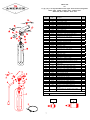
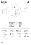
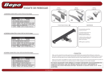
SERVICE MANUAL
NO. 14425
for
AMEREX
HALOTRON I
HAND PORTABLE
“CLEAN AGENT” FIRE EXTINGUISHERS
(FOR NON-RESIDENTIAL APPLICATIONS)
* * * HAVE EXTINGUISHERS RECHARGED IMMEDIATELY AFTER ANY USE * * *
All fire extinguishers should be installed, inspected and maintained in accordance with the National Fire
Protection Association standard titled "Portable Fire Extinguishers", NFPA-10 and the requirements of local
authorities having jurisdiction.
When maintenance is indicated it should be performed by trained persons having proper equipment. Fire
extinguishers are pressure vessels and must be treated with respect and handled with care. They are
mechanical devices and require periodic maintenance to be sure that they are ready to operate properly and
safely. Amerex strongly recommends that the maintenance of portable fire extinguishers be done by a trained
professional – your local authorized Amerex Distributor.
Amerex Corporation makes original factory parts available to insure proper maintenance – use of substitute
parts releases Amerex of its warranty obligations. Amerex parts have machined surfaces and threads that are
manufactured to exacting tolerances. O-rings, hoses, nozzles, and all metal parts meet precise specifications
and are subjected to multiple in-house inspections and tests for acceptability. There are substitute parts
available that are incorrectly labeled as UL component parts, some are advertised as Amerex type. None of
these meet UL requirements and all of them voids the Amerex extinguisher warranty and UL listing. DO NOT
SUBSTITUTE.
REFERENCES IN THIS MANUAL:
NFPA-10 Portable Fire Extinguishers
AVAILABLE FROM:
National Fire Protection Association
1 Batterymarch Park, P. O, Box 9101
Quincy, MA 02269-9101
CGA C-1 Methods for Hydrostatic Testing of
Compressed Gas Cylinders
CGA C-6 Standard for Visual Inspection of
Compressed Gas Cylinders
Compressed Gas Association, Inc.
4221 Walney Road, 5th Floor
Chantilly, VA 20151-2923
AMEREX CORPORATION – P.O. BOX 81 – TRUSSVILLE, ALABAMA 35173-0081
Phone: (205) 655-3271
Fax: (800) 654-5980
Web Page: http://www.amerex-fire.com
e-mail: [email protected]
Printed in U.S.A.
OM14425D-02/05
INTRODUCTION
This manual covers specific instructions for the Amerex Halotron I hand portable extinguishers. Special
maintenance and recharge instructions contained in this manual apply to these extinguishers only.
Halotron I “Clean Agent” extinguishers are designed for Class A, B, and C hazards formerly protected
with Halon 1211 extinguishers. They contain dichlorotrifluoroethane (R-123), which is designated for
streaming fire extinguisher applications. Halotron I is listed in the U.S. Environmental Protection Agency
(EPA) “Significant New Alternative Policy” (SNAP) as acceptable for nonresidential applications. Halotron
I has acceptable toxicity and cardiac sensitization levels for use in occupied spaces when used according
to the instructions on the nameplate and rules of the EPA SNAP Program.
PHYSICAL PROPERTIES OF HALOTRON I
Primary Component
Dichlorotrifluoroethane (R-123) or (HCFC-123)
Boiling Point
80.6°F [27°C]
Liquid Density
92.3 lb./ft³ (1.48 kg / liter)
Gas Density
0.385 lb./ft³ (6.17 kg / m³)
Molecular Weight
150.68
Physical State
Pressurized Liquid
Vapor Pressure @ 68ºF [20ºC] (liquid alone) 11.2 psi [77 kPa]
Pressure of mixture in Container @ 68ºF [20º] 95 psig in bulk container
AMEREX CORPORATION DOES NOT SERVICE, MAINTAIN OR RECHARGE FIRE EXTINGUISHERS.
THIS MANUAL IS PUBLISHED AS A GUIDE TO ASSIST SERVICE PERSONNEL IN THE INSPECTION,
MAINTENANCE AND RECHARGE OF AMEREX FIRE EXTINGUISHERS ONLY. NO INSTRUCTION
MANUAL CAN ANTICIPATE ALL POSSIBLE MALFUNCTIONS THAT MAY BE ENCOUNTERED IN THE
SERVICE OF FIRE EXTINGUISHERS.
AMEREX ASSUMES NO LIABILITY FOR SERVICE,
MAINTENANCE OR RECHARGE OF FIRE EXTINGUISHERS BY PUBLISHING THIS MANUAL.
INSTALLATION
THIS MANUAL SHOULD BE CAREFULLY STUDIED BY ALL WHO MIGHT USE OR SERVICE THE
EXTINGUISHER. STORE IT IN A CONVENIENT PLACE FOR EASY REFERENCE.
Your layout and particular hazards dictate the placement of fire extinguishers. NFPA-10 (1-6.9) recommends
that hand portable extinguishers with a gross weight less than 40 lbs. be hung with the top of the extinguisher
not more than 5 ft. (1.53 m) above the floor. Extinguishers having a gross weight greater than 40 lbs. (18.14
kg) should be installed so that the top of the extinguisher is not more than 3 ½ ft. (1.07 m) above the floor. All
extinguishers should be in an accessible location and near an exit. Never install the extinguisher in a location
where a potential hazard would prevent easy access.
The o p erati onal temperature range is -40°F to +120°F (-40°C to +60°C). The extinguisher must be
protected if temperatures outside of these ranges are anticipated. Never throw an extinguisher into a
fire because rapid heat buildup could cause pressure expansion and exceed the limitations of the cylinder.
MOUNTING INSTRUCTIONS
Your extinguisher should be mounted in a clean, dry area accessible to the fire hazards and
preferably near an exit. Hang it so that the top is from 3½ to 5 feet above the floor and out of
the reach of small children. Use the mounting bracket furnished with the extinguisher. Fasten to a
solid surface using strong screws or fasteners (not included). Follow the Mounting Instructions below.
1
MOUNTING INSTRUCTIONS
U/L specifies that the hanging device must withstand a vertical force of five times the weight of the
charged extinguisher but not less than 100 pounds. The extinguisher bracket should be mounted as
follows:
WALLS WHERE 2 X 4 STUDS CAN BE FOUND
Mount wall hanger bracket securely to stud
using two No. 10 x 1¼ inch long wood screws through the diagonal smaller holes in the bracket.
SHEET ROCK Mount a ¾ inch thick board to wall using 3/16 inch toggle bolts.
Board should
extend a minimum of two inches beyond all sides of the extinguisher profile (excluding hose and
wand). Mount hanger racket to board using two No. 10 x 1 inch long wood screws as above.
CINDER BLOCK OR CEMENT Mount wall hanger bracket using one ¼ inch toggle bolt or masonry
lead screw expansion anchor through center hole in wall bracket.
CONCRETE OR TILE WALLS
Mount wall hanger bracket using one ¼ inch masonry lead screw
expansion anchor through center hole in wall bracket. FOR TILE WALLS – locate in joint.
STEEL POSTS OR BEAMS Special tools and fasteners are required – have extinguisher mounted
by a professional fire extinguisher service company.
OPERATION
WARNING:
PERSONS EXPECTED TO USE THIS EXTINGUISHER SHOULD BE MADE AWARE
OF THE CONFINED SPACE LIMITATIONS AND TRAINED IN INITIATING ITS
OPERATION AND PROPER FIRE FIGHTING TECHNIQUE. THE CONCENTRATED
AGENT CAN PRODUCE TOXIC BY-PRODUCTS. AVOID INHALATION OF THESE
MATERIALS BY EVACUATING THE CONFINED SPACE.
DO NOT USE IN
CONFINED SPACES SMALLER THAN THE MINIMUM STATED ON THE
EXTINGUISHER LABEL.
1. Remove extinguisher from wall hanger bracket.
2. Hold extinguisher upright, twist and pull ring (safety) pin.
3. Start back a minimum of 8 feet from the fire. Aim the nozzle at the base of the fire nearest
you.
4. Keeping the extinguisher upright, squeeze the lever to discharge. Sweep the agent stream from
side to side.
5. Evacuate and ventilate the area immediately after extinguishing the fire. The fumes and smoke
from any fire may be hazardous and can be deadly.
WARNING: SYMPTOMS OF OVER-EXPOSURE TO PURE Halotron I MAY CAUSE CENTRAL
NERVOUS SYSTEM EFFECTS SUCH AS DIZZINESS, DROWSINESS, ANESTHESIA, OR
UNCONSCIOUSNESS.
PERSONS SUFFERING FROM OVER-EXPOSURE SHOULD BE
IMMEDIATELY REMOVED TO AREA WITH FRESH AIR. APPLY ARTIFICAL RESPIRATION IF
NECESSARY. CONTACT A PHYSICIAN.
INSPECTION
Extinguishers should be INSPECTED when initially placed in service and at regular intervals (monthly or more
often if circumstances dictate) to insure they are ready for use. Inspections may be accomplished manually or,
in some cases, by electronic monitoring.
2
INSPECTION [NFPA-10] is a "quick check" that a fire extinguisher is available and is in operating
condition. It is intended to give reasonable assurance that the fire extinguisher is fully changed.
Inspections may be accomplished manually, or in some cases by electronic means.
PERIODIC INSPECTION PROCEDURES
(monthly or more often if circumstances dictate)
This extinguisher should be inspected at regular intervals (monthly or more often if circumstances dictate) to
insure that it is ready for use.
A "quick check" should be made of the extinguisher for the following:
1.
2.
3.
4.
5.
6.
7.
Location in designated place
No obstruction to access or visibility
Operating instructions on nameplate legible and facing outward
Safety Seals and tamper indicators not broken or missing
Determine fullness by weighing or "hefting"
Examination for obvious physical damage, corrosion, leakage, or clogged nozzle
Pressure gauge reading in the operable range
MAINTENANCE
Extinguishers should be subjected to maintenance at intervals of not more than 1 year, at the time of
hydrostatic test, or when specifically indicated by an inspection or by electronic notification.
Maintenance procedures include a thorough examination of the basic elements of a fire extinguisher:
1.
2.
3.
Mechanical parts
Extinguishing agent of cartridge operated extinguishers, pump tanks and certain
types of stored pressure extinguishers
Expelling means
NOTE: Stored pressure Halotron I extinguishers do not require an internal
examination of the cylinder or examination of the agent during annual
maintenance, but shall receive a thorough external examination.
Maintenance [NFPA 10] Maintenance is a thorough examination of the fire extinguisher. It is intended to
give maximum assurance that a fire extinguisher will operate effectively and safely. It includes a thorough
examination for physical damage or condition to prevent its operation and any necessary repair or
replacement. It will normally reveal the need for hydrostatic testing.
MAINTENANCE/SERVICE PROCEDURE
1.
Clean extinguisher to remove dirt, grease or foreign material. Check to make sure that the instruction nameplate
and UL manifest are securely fastened and legible. Inspect the cylinder for corrosion, abrasion, and dents or weld
damage. If any of these conditions are found and you doubt the integrity of the cylinder, hydrostatically test to
factory test pressure, using the proof pressure method in accordance with CGA C-1 and NFPA 10.
NOTE: When cleaning avoid use of solvents around the pressure gauge. They could seriously damage the plastic
gauge face.
3
2.
Inspect the extinguisher for damaged, missing or substitute parts. Only factory replacement parts are approved
for use on Amerex fire extinguishers.
3.
Weigh extinguisher and compare with weight printed in the Maintenance section on the nameplate.
extinguisher if weight is not within indicated allowable tolerances.
4.
Check the date of manufacture on the extinguisher nameplate. Cylinder must be hydrostatically (proof pressure)
tested every 12 years to the test pressure indicated on the nameplate. Check the last date complete maintenance
was performed. Per NFPA 10 these extinguishers shall be emptied and subject to complete maintenance every six
years. All maintenance/service and recharge procedures shall be done at that time.
Visually inspect the pressure gauge:
a. if bent, damaged or improper gauge, depressurize and replace.
b. If pressure is low, check for leaks
c. if pressure is low or high and temperature/pressure relationship has been ruled out:
1. Low pressure – check for leaks. Follow procedure for reclaiming Halotron I agent, install necessary
part(s) to repair leak and recharge according to instructions.
2. High pressure (over pressurized or over charged) - depressurize and recharge extinguisher following
instructions in Recharge section.
5.
Recharge
6.
Remove nozzle or hose and nozzle assembly and inspect for damage. Blow air through nozzle or hose and nozzle to
insure that passage is clear of foreign material. Replace component parts with proper Amerex part as necessary.
7.
Check ring pin for freedom of movement by breaking the seal and removing the pin. Replace the ring pin if bent or
if removal is difficult.
8.
Inspect discharge lever for dirt or corrosion that might impair freedom of movement. Inspect carrying handle for
proper installation. If lever, handle or rivets are damaged or distorted, replace with proper Amerex part(s).
9.
Inspect valve assembly for corrosion or damage to hose thread connection. Replace valve assembly or component
parts as necessary following the proper depressurization and recharge procedures. If valve removal is necessary
complete all steps in the Recharge Procedure.
10. Install nozzle or hose and nozzle assembly.
11. Install new tamper seal and record service data on the extinguisher inspection tag.
12. Rehang the extinguisher on the wall hanger bracket making sure that it fits the hanger bracket properly – replace
the bracket if necessary.
RECHARGE
Recharging [NFPA-10].
extinguisher.
a.
b.
The replacement of the extinguishing agent and also includes the expellant for this type of
WARNING
Halotron service should be performed only in a well ventilated room by a properly trained service
technician wearing proper eye protection and rubber gloves.
Before attempting to recharge be sure this extinguisher is completely depressurized by slowly and
carefully depressing the operating lever and discharging the extinguisher into a proper collection area.
4
c.
Use a regulated pressurizing source using ARGON ONLY. Set the regulator to no more than 25 psi
higher than the extinguisher gauge operating pressure.
d.
Check and calibrate regulator gauge at frequent intervals. The regulator gauge should be used to
determine when the intended charging pressure has been reached.
DO NOT USE THE
EXTINGUISHER GAUGE FOR THIS PURPOSE.
e.
Never leave an extinguisher connected to a regulator of a high pressure source for an extended period
of time. A defective regulator could cause the cylinder to rupture due to excessive pressure.
RECHARGE
Note: The following procedure is for an EMPTY Halotron I extinguisher. If you are recharging an
extinguisher, which has been partially discharged (with agent remaining in the cylinder) or has been
recharged and the pressure leaked, follow the instructions contained in the Recharging Instructions
packaged with the Amerex Recharge Kit (P/N 14538) or with Getz Halotron recovery equipment.
1.
Complete items 1 through 9 in Maintenance Service Procedure above.
2.
Verify that there is no pressure remaining in the extinguisher.
3.
Remove the valve assembly by turning it counter clockwise. Disassemble by removing downtube
assembly (use a wrench on the downtube retainer, not the tube), spring and valve stem from the valve
assembly.
4.
REMOVE AND DISCARD THE COLLAR O-RING AND VALVE STEM ASSEMBLY. Inspect and clean
the spring with a clean, dry cloth – replace if worn or damaged. Clean internal valve body surfaces and
threads with a soft bristle brush making sure that the valve stem seating area is not scratched. Install
a new (green) collar o-ring and valve stem assembly (green seal). Lightly lubricate the collar o-ring and
small o-ring on the valve stem with Visilox V-711 (do not lubricate the valve stem seal). Inspect the
downtube. If it is damaged replace with proper downtube (see Parts List). Install downtube securely.
NOTE: Valve assemblies are not indexed. Keep original valve assembly/cylinder combinations together
while performing maintenance or recharge to assure proper nameplate orientation.
5.
Inspect the interior of the cylinder following CGA Visual Inspection Standard, C-6.
6.
Install the valve assembly to the cylinder in a clockwise direction Install the proper Amerex recharge
adapter and draw a vacuum of 27" of mercury (adjusted for altitude variations – see your vacuum pump
manual for detailed instructions). Place the extinguisher on a scale and tare weight prior to filling.
7.
Connect the extinguisher to a Halotron I supply cylinder using the Amerex P/N 14538 Halotron I
Recharge Kit or equivalent.
NOTE: The Halotron I supply cylinder MUST be pressurized to approximately 100 psi with ARGON at
all times.
5
8.
Depress the operating lever and fill extinguisher with the amount of agent specified on the nameplate
USING ONLY CLEAN, UNCONTAMINATED HALOTRON I AGENT. (See detailed instructions on your
recharging system).
CAUTION: AVOID LIQUID HALOTRON I CONTACT WITH EXTINGUISHER CYLINDER. WIPE DRY
IMMEDIATELY WITH A CLEAN CLOTH.
9.
Pressurize to the extinguisher operating pressure with ARGON only. Repeatedly rock the extinguisher
to thoroughly mix the ARGON pressurizing gas until proper pressure is reached. Add additional
ARGON as necessary until the pressure stabilizes.
10.
Check for leaks at the gauge, valve outlet and valve/cylinder connection using a halogen type leak
detector or leak detection fluid. DO NOT USE SOAPY WATER! Thoroughly remove all leak detection
fluid residue from the valve assembly and cylinder. Remove recharge adapter.
CAUTION: IF YOU USE A HALOGEN TYPE LEAK DETECTOR A RESIDUAL AMOUNT OF
HALOTRON I WILL REMAIN IN THE VALVE BODY UNTIL THE LIQUID EVAPORATES. TO
PROPERLY LEAK TEST USING THE HALOGEN LEAK DETECTOR IT IS RECOMMENDED THAT
THE EXTINGUISHER BE SET ASIDE A MINIMUM OF 24 HOURS AFTER RECHARGING, THEN
LEAK TESTING.
11.
Place nozzle or hose and nozzle on scale with extinguisher. Weigh and confirm that the total weight is
within the allowable tolerances indicated in the maintenance section of the extinguisher nameplate.
12.
Install nozzle or hose and nozzle assembly.
13.
Install ring pin with ring facing front of the extinguisher. Install new tamper seal. Record recharge
date and attached new recharge tag.
TROUBLE SHOOTING GUIDE
WARNING: DETERMINE THE SOURCE OF A LEAK BEFORE THE EXTINGUISHER IS
DEPRESSURIZED.
THE EXTINGUISHER MUST BE COMPLETELY DEPRESSURIZED BEFORE ANY
ATTEMPT IS MADE TO REMOVE THE VALVE ASSEMBLY AND CORRECT THE LEAKAGE PROBLEM.
SEE INSTRUCTIONS PACKAGE WITH THE AMEREX HALOTRON I RECHARGE KIT P/N 14538 OR
GETZ HALOTRON RECOVERY SYSTEM FOR THE PROPER METHOD OF DEPRESSURIZING THE
EXTINGUISHER TO AVOID UNNECESSARY DISCHARGE AND MINIMUM AGENT LOSS.
1.
2.
3.
4.
6.
*
PROBLEM
Leak at collar o-ring
CORRECTIVE ACTION
Remove valve assembly, clean collar thoroughly and install new ring.
(Optional)
Leak through valve
Install new valve stem assembly. Check valve seat for scratches or
foreign matter
Leak around gauge threads Remove gauge* and reinstall using Teflon tape on the gauge threads
Defective gauge
Remove defective gauge* and install a new gauge using Teflon tape on
the gauge threads.
Leak in cylinder
Contact Amerex if under warranty, otherwise mark “REJECTED” and
return to owner.
Pressure gauge threads are coated with a special epoxy at the factory. For easy removal soak the
valve assembly in hot water (180° F/82°C) for two to four minutes. Remove gauge with a 7/16” open
end wrench.
6
PARTS LIST
For
1.4,2½,5,5½ 11 & 15½ HALOTRON I Clean Agent Stored Pressure Extinguishers
Models A384, A/B385, A/B386, B394 – Aluminum Valve
Models 387,397 & 388,398 – Brass Valve
Item
No.
1
1A
2
3
3A
4
4A
5
Part
No.
14527
14525
14526
17051
16694
14436
14449
14407
14408
14409
06978
01532
00160
5A
01412
6 & 6A
7 & 7A
8
8A
9
00532
01387
07762
06067
11825
02625
01563
9A
01060
10 & 10A
10A
12
14418
14417
16332
09020
09001
11826
09002
01564
12A
01064
13
13A
14
14A
15
15A
16
16A
17
17A
17A
18
19
19A
13305
14268
13288
14327
05243
05235
00383
01074
15507
14285
06069
01075
06212
14778
14568
14569
20
03038
20A
03610
11
11A
NOTE:
Std.
Pkg.
Replacement valve assemblies include new valve body, gauge, handle and lever.
19 & 19A
7
Description
Vlv Asy–387/388, 397/398
Vlv Asy–A384
Vlv Asy–A/B385, A/B386
Vlv Asy – B394
Hanger Loop & Screw–387/388, 397/398
Hose & Noz Asy-387/397 (.247)
Hose & Noz Asy-388/398 (.295)
Nozzle – A384 (.121)
Nozzle – A/B385 (.166)
Nozzle - A/B386, B394 (.277)
O-ring (hose) – 387/388, 397/398
O-ring (nozzle) – A384, A/B385, A/B386, B394
Ring (safety) Pin SS – 387/388, 397/398
Ring (safety) Pin AL – A384, A/B385,
A/B386, B394
Chain (Nylon) for Ring Pin – ALL
Lock Wire Seal (yellow) – ALL
Lever & Rivet – 387/388, 397/398
Lever & Rivet – A384
Lever & Rivet - A/B385, A/B386
Lever & Rivet – B394
Rivet only for Lever – 387/388, 397/398
Rivet only for Lever – A384, A/B385,
A/B386, B394
Gauge 125 psi – 387/388, 397/398 & A384
Gauge 100 psi - A/B385 & A/B386
Gauge 150 psi – B394
Handle & Rivets – 387/388, 397/398
Handle & Rivet – A384
Handle & Rivet – A/B385 & A/B386
Handle & Rivet – B394
Rivet only for handle (2 Req'd) 387/388, 397/398
Rivet Only for Handle (2 Req'd) – A384, A/B385,
A/B386, B394
Collar O-ring – 387/388, 397/398
Collar O-ring – A384, A/B385, A/B386, B394
Vlv Stem Asy – 387/388, 397/398
Vlv Stem Asy – A384, A/B385 A/B386 & B394
Vlv Stem O-ring – 387/388, 397/398
Vlv Stem O-ring – A384, A/B385 & A/B386
Spring – 387/388, 397/398
Spring – A384, A/B385 A/B386. B394
Dtube/Retainer Asy –397/398
Dtube/Retainer Asy – 387/388
Dtube/Retainer Asy – A384
Dtube/Retainer Asy – A385
Dtube/Retainer Asy – A/B386, B385, B394
Strap & Clip Asy (blk plastic) – 387/388, 397/398
Fill Adapter – 387/388, 397/398
Fill Adapter – A384, A/B385 A/B386, B394
Hydrotest Adapter (1¼" – 12UN2B) – 387/388,
397/398
Hydrotest Adapter (1" – 12UN2B) – A384, A/B385,
A/B386,B394
20 & 20A