1
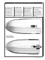
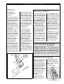
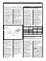
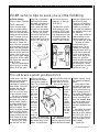
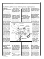
Spring 1994
The Kawasaki Technical Magazine
Vol. 7 No. 1
by Patrick Kelly
Instructional Designer/
Instructor
If you followed personal
watercraft racing this past
season, you couldn’t have
missed it. The competition
probably wishes they had
never seen it.
“It” was the Kawasaki
Super Sport Xi modified
by Performance Jet Ski
and ridden to the IJSBA
World and National Pro
Runabout championships
by John Stevens.
Now, a version of this
machine is available to the
serious JET SKI® watercraft enthusiast. Introducing the JH750-D1 or,
simply, the XiR.
The hull
The XiR is based on
our Super Sport Xi, with a
few important differences.
One of the biggest differences is the hull: The XiR
hull is virtually identical to
the one used on John
Stevens’ championshipwinning boat. It differs
from the Xi hull from the
bond line down. There is
now an extra strake on
each side of the hull
bottom. This extra strake
helps improve the XiR’s
cornering as well as its
straight line abilities. Also
for improved cornering
and stability, there are
longer sponsons on the
XiR hull. These additions
are especially effective in
the rough water conditions
found in competition.
CONTINUED ON PAGE 2
ROUTE LIST: o SERVICE o PARTS
o SALES
P L E A S ER E T U R NT OS E R V I C EL I B R A R Y
Inside!
n Service tips & more!
S H O P
The XiR
CONTINUED FROM PAGE 1
The engine and pump
location in this hull is also
new. The engine and
pump have been moved
rearward as far as possible. Their new location
moves both the center of
mass and the pump inlet
rearward, helping to keep
the pump hooked up in
choppy waters.
The hull is constructed
of carbon fiber-reinforced
RTM, while the deck—
identical to the standard
Super Sport-is made of
SMC. The RTM bottom is
gel coated inside and out
and then painted on the
outside to match the deck.
T A L K / T E C H N I C A L
Also new is the seat.
To help the rider hang on
under severe cornering,
the XiR seat is thicker
than the Xi seat and has a
non-slip cover.
The engine in the XiR
is basically identical to the
one used in the Xi. The
exhaust system is, however, completely new,
from the exhaust manifold
to the exhaust outlet. The
exhaust system now goes
around the front of the
engine, makes a 90-degree
turn and then enters the
rear portion of the hull.
Inside the hull is a
waterbox muffler. The
exhaust exits the top of
the waterbox muffler and
comes up through the hull.
A rubber hose connects it
to the other side of the hull
where it goes back down
into the hull to the exhaust
outlet. The outlet is located in the jet pump tunnel,
facing the jet pump at a 90degree angle. This location keeps exhaust noise
to a minimum.
To maximize the
effectiveness of the new
exhaust, the carburetor
jetting has been recalibrated. The new exhaust
system boosts horsepower
output to 84 at 6750 rpm.
Another change to the
engine package is a
different igniter than the
other 750 watercraft. It
has a higher rev limit
potential to take advantage
of the engine’s potential
for modification.
Also, for added simplicity and flexibility, the
Superlube oil injection
system has been removed.
The engine is now lubricated by pre-mix at a ratio of
50:1.
The jet pump in the XiR
is a standard 750-style jet
pump with a few changes.
The biggest is a new threeblade, stainless steel
impeller. This is a variedpitch impeller for maximum acceleration with
minimum cavitation. The
pitch varies from 9° to 17°.
The pump exit nozzle is
also new. Since the XiR
does not utilize a trim
adjustment system, the
XiR wonders (CLOCKWISE FROM ABOVE, LEFT): 743cc engine boasts a new igniter, modified waterbox and high
performance pipe; nozzle and pump are from the 750SX; sponsons add considerably to cornering capabilities; additional strakes molded into the new RTM/carbon fiber hull improve straight line stability in rough racing conditions.
2
l
K-Tech News
S H O P
exit nozzle does not need
mounting bosses for the
nozzle trim pivot points.
Because of this, the exit
nozzle from the JS750SX
is used. A quick-turn
steering nozzle incorporating a vertical vane for
more responsive cornering completes the XiR
pump. The XiR generates
T A L K / T E C H N I C A L
675 pounds of thrust.
In spite of the XiR’s
performance nature, it
does retain some convenience features. There is
still a fuel gauge located in
front of the seat. The temperature warning system
found on our other 750
watercraft is retained,
along with the tempera-
ture warning light which is
located next to the fuel
gauge. The XiR has the
same ample storage as
the Super Sport and
Super Sport Xi, with
compartments in the bow
and also in the stern. A
hull drain makes cleaning
and flushing the engine
compartment a breeze.
There are even stainless
steel eye hooks at the
stern and the bow to make
trailering easier.
The XiR reinforces
Kawasaki’s leadership
position in the watercraft
industry, and will firmly
establish Kawasaki as the
leader on the race course
as well. o
A graphic comparison
between the Xi (TOP) and
new XiR (BOTTOM) hulls.
The Technical Magazine
l
3
G U E S T
Spring 1994
Vol. 7 No. 1
©1994 Kawasaki Motors
Corp., U.S.A. (KMC).
All rights reserved.
The KLX650’s stunning Baja success
K-Tech News Staff
by Steve Nickless
K-Tech News Prod. Asst.
Publisher
Kawasaki Tech Services
As was mentioned in the
Publications Manager
Don Church
Executive Editor
Gary Herzog
Editor-in-Chief
Gregg Thompson
Communications Editor
Patrick Kelly
Regional Editors
North and East
Fred DeHart
Central and South
Walter Rainwater
Contributors
Dave Behlings, Jerry Heil,
Kenny Osberg, John Porno,
David Pyle, Steve Rice,
Mary Sola, Ray St. John
Graphics/Production
Graphic Art
Gregg Thompson
Photography
Dave Corey
Copy Editor
Pat Shibata
Production
Nickless Communications
Published by Kawasaki.
All suggestions become the
property of KMC. Sending a
service suggestion gives
Kawasaki permission to publish
and/or use it without further consideration.
Specifications subject to change
without notice.
4
l
K-Tech News
S P O T
last issue of K-Tech
News, Kawasaki’s Team
Green racing division did
the impossible once again
by claiming an unprecedented sixth consecutive
overall victory in last
November’s Baja 1000.
Not to be overlooked in
all the post-race hoopla,
however, was another
similarly impressive achievement by Team Green in
the same event: the thirdplace finish by its still-new
competition KLX650.
Pushed to its limits by
Baja veterans Paul Krause,
Garth Sweetland and Ted
Hunicutt Jr., the big fourstroke machine surprised
everyone (except, perhaps,
stock KLX650 customers!)
in finishing so far up the
field despite a time-limited
test program.
Indeed, Team Green
was forced to squeeze
work in on this particular
Kawasaki model around
one of its most ambitious
-and successful--summers of racing ever. Busy
on the desert and in the
amateur motocross ranks,
the green team’s manpower was spread thin.
Obviously, the stock KLX
was a fine platform from
which to begin . . .
The time element was
only one of the challenges
Team Green boss Mark
Johnson and his technicians accepted in
undertaking the KLX650
Baja bike project. Another
was the formidable speed
and reliability baseline
already established by the
team’s awesome, twostroke KX5OOs.
Turning a production
enduro motorcycle--even
one as sturdy as the new
KLX—into a race bike
capable of taking Bajastyle punishment for nearly
16 hours is no easy feat.
Team Green approached
this one as they do all new
machines: by looking at
every component and subsystem in light of the competition rule book and Kawasaki’s overall objectives.
In desert racing, reliability is “job one.” In the
grueling 1,000 miles of
Baja, it’s a big job no
matter what bike you are
preparing. But engineering
for reliability is made
much more complicated
by the need for speed.
It wasn’t enough just to
finish the race. For Team
Green, the objective was
to finish high in the standings. The team couldn’t
just dive in and start beefing up stock components.
In some areas they had to
start from scratch with new
(and costly) processes or
materials to save weight
rather than add it.
There’s no catalog to
turn to, either: Team
Green was forced to
hand-fabricate (or farm
out to specialists the fabrication of) many components including shock
absorbers, exhaust pipe
and a unique, heavily
gusseted swingarm.
Many of the changes
made to the stock machine
are invisible. One that’s
quite obvious is the lighting
system, developed over
the last several years on
the all-conquering 500’s.
Designed in cooperation with lighting producer
PIAA, the 650’s massive
spotlights live in a spider
web of steel tubing and
connecting links.
Lights that turn with the
handlebars are only the
beginning. The vibration
that accompanies the incredible speeds reached
in the Baja event is another problem. Then there
are the weight concerns—
every ounce high and up
front can be harmful to
handling. The beams
themselves must be protected from flying rocks.
And the bulbs must be
easy to change.
These are not simple,
garden variety challenges.
Coming up with solutions
to the lighting problem
alone took several thousand
hours . . . and dollars.
But make no mistake
about it, this amazing third
place finish is a testimony
to the outstanding
capabilities of this durable
new machine. Taking
nothing away from the
expert preparation done
by the Team Green staff,
the eye-opening success
of its first Baja 1000
appearance could never
have been achieved with
anything less than a great
production vehicle.
Team Green’s Johnson
adds, “Contrary to the
comments of some magazine editors,” says Team
Green’s Johnson, “the
KLX650 did not overheat
in any one of its maiden
outings.”
And by the end of the
year, Mark notes, it was
making more power than
the two-stroke 500 . . . o
C O M M U N I C A T I O N S
Micro-K
by David Pyle
Parts Publications
Specialist
In the last few months I
have received quite a few
questions regarding the
‘circled letters” that are
shown on some parts
grids. The purpose of
these letters is to make it
easier to find a part and
he point where it attaches
on a vehicle.
Many times there is not
enough room on the
illustration to spread out
aII the parts in the proper
location. By showing the
circled letter next to the
part and next to its
location on the frame,
identifying the correct
parts is made easier.
In the sample
lustration of the KX250K1 Frame Fittings grid,
here are circled letters A
thru E. These letters show
he correct location of A,
he top motor mount bolt;
I, the front motor mount
bolt; C, the bottom motor
TECHNICALITIES
mount bolt; and D and E,
the top and bottom chain
rollers and bolts. It would
be far too confusing to try
and connect the lines with
the parts and the frame.
Just remember: When
you see a part with a letter
in a circle next to it, there
will be another letter in a
circle somewhere else on
the page showing its
proper location.
lI
have also received
some calls regarding
decals on street bikes.
What decals come on
painted body parts? All
decals come on painted
body parts. Most plastic
emblems have to be
ordered separately. ZX1100-D tank emblems are
not supposed to come on
replacement parts; last
year, however, some were
supplied by mistake.
A chart in K-Tech New
Vol. 5 No. 1 shows vehicle
type and whether its parts
come with decals or not. o
Missing numbers
Some of you may have
noticed in the latest Retail
Price Guide that there are
some numbers missing.
To be more precise, any
part number that has
been canceled for 10 or
more years is no longer
shown in the guide.
This causes some
problems when looking up
parts on the older microfiche. We don’t change
the part numbers on the
microfiche every time
there is a part number
change, of course. (If we
did, your inventory could
have stock with no reference to it, and we would
be sending out so many
microfiche that you would
need a second mail box!)
So, what would I do?
Well, for starters, I would
keep a few old price guides
around for reference. But,
if it’s too late and you’ve
already recycled your old
ones, here are a few tips:
Model Application
Guide: Using the M.A.G.
will help you find the latest
substitute numbers for old
parts you have in stock so
that you can go back to
the price guide for pricing
info.
K-Share: Run an “Item
Status Inquiry” on K-Share.
If you enter any number
on K-Share, it will show
the latest substitute
number even if it is not
shown in the retail price
guide. —Dave Pyle
TECHNICALITIES
XiR assembly and prep.
Believe it or not, there is with the boat!
already an Assembly and
Preparation sheet for the
new XiR. To make sure
that everyone who needed
the A&P sheet got one, we
packed them in the crate
This is a limited-production model, so we did not
do a general mailing of the
A&P the way we would for
a high-production quantity
model. —Ray St. John
SALES TOOLS
How We Stack Up ’94
Recently you received a
supply of How We Stack
Up 1994 booklets. We
hope you have already put
them to use training your
sales staff in the features
and benefits of the ’94
Kawasakis. The booklet is
designed to be carried in a
sales person’s pocket at
all times to help out in
answering customers’
questions.
If you need more
copies, call your Distict
Manager, your Regional
Sales Manager, or the
Technical Services Division of Kawasaki Motors
Corp., U.S.A., (714) 7700400, x2472.
—Ray St. John
The Technical Magazine
l
5
T I P S
F R O M
T H E
Charcoal canister fouling
by Gregg Thompson
Product Support Supervisor
You
dealer technicians
who are not real familiar
with the California Evaporative Emissions system
could be fooled into some
unnecessary diagnostic
work if the customer
doesn’t read (and follow)
he instructions in his
owners manual. So here’s
I little briefing:
The owners manual for
any of our street legal
our-stroke bikes tells the
Once that happens, the
system doesn’t vent properly and you can get all
the symptoms that go
along with a plugged vent
in the fuel system-like
hard starting, throttle
hesitations, or apparently
running out of fuel while a
sustained highway
speeds.
If a California model
comes into your shop with
these symptoms, disconnect the (blue) fuel tank
vent line from the back of
the tank and the (yellow)
S P E C I A L I S T S
TECHNICALITIES
ZX1100-D rod bearings
There are numerous
errors in the rod bearing
selection charts in the
ZX1100-D service
manual. There are errors
in the chart on the specifications pages (pg. 8-5)
of the crankshaft/transmission chapter, as well
as the chart in the text
(pg. 8-13) of that chapter.
Not only are the two
charts full of errors, but
they are different from
each other as well!
Mostly what you have
to be careful of is the part
numbers for the bearings.
Con-Rod Big End
Bore Diameter
Marking
—Gregg Thompson
Crankpin
Diameter
Marking
Size Color
Part Number
Blue
92028-1680
¡
¡
None
None
¡
None
¡
None
They are all incorrect on
both charts. However, you
should also note that the
chart on the specifications
page has a “none” on the
top line under the “Crankpin Diameter Marking”
heading. It should have an
“O” in that space.
In your ZX1100-D
Service Manual, the
Connecting Rod Big End
Bearing selection charts
should look like the chart
below. Make the appropriate corrections in your
service manuals.
Bearing Insert
White
92028-1681
Black
92028-1679
Connecting rod big end bearing insert selection chart.
PUBLICATIONS
Watercraft general
assembly and prep. manual
customer (the one who
takes the time to read it)
not to fill the gas tank so
full that the fuel rises into
the filler neck.
That’s good advice for
the customer, and something you need to be
aware of too.
If the fuel tank is overfilled (that is, filled to the
bottom of the filler neck or
higher), so much fuel will
be forced out of the fuel
tank vent (into the blue
tube) and down the (red)
return tube that the charcoal canister will become
fouled with liquid fuel.
6
l
K-Tech News
carb vent line from the
charcoal canister, and ride
the bike. If the symptoms
are gone, the problem is a
fouled canister.
You can dry the canister
out by setting it out in the
warm sun for a couple
days. Or you can fix it in a
few hours by connecting a
low-pressure air supply
(such as an aquarium
pump) to the (blue) vent
line inlet on the canister
and letting the pump blow
air through it. o
I f you’re a Kawasaki JET
SKI@ watercraft dealer,
you recently received your
free copy of the “Kawasaki
Watercraft General Assembly and Preparation”
manual. This book is
designed to be used with
supplementary A&P
sheets covering those
parts of the preparation of
each model which are
unique to it.
Earlier this year, you
got the A&P sheet for the
1994 model Super Sport
Xi. You were instructed to
use it with the A&P manual for the ’93 model Xi.
Well, now you can use
it the way it was meant to
be used: with the Kawasaki Watercraft General
A&P Manual.
—Ray St. John
T I P S
F R O M
T H E
S P E C I A L I S T S
ZX-9R service tips to save you a little fumbling
by David Behlings
Product Support Specialist
Tank removal
Here’s a tip that might
save you a little fumbling.
Most of us figure we can
remove a fuel tank without
reading the service manual,
right? It’s simple: If it’s got
front mounting bolts, remove those and then get
the seat off. Loosen the
back of the tank (probably
a couple bolts) and lift the
back of the tank enough to
reach in and disconnect
the fuel line(s) and fuel
sensor. Now, brace yourself (some tanks weigh
more than 40 Ibs. when
full of gas) and yank that
dude off there.
Well, that sounds about
right for most of our bikes.
But the ZX-9R has some-
thing else to remember: a
fuel knob that is right in
the middle of the main LH
frame member (the petcock is inside the frame;
the knob is on the outside).
Before you lift the tank
off the bike, you should
remove the fuel knob from
the petcock (there’s a
small Phillips screw in the
center of it). That way you
don’t take a chance on
breaking it off when you
lift the tank up.
Carburetor parts
While working on some
production ZX-9R’s here,
we noticed some interesting things about the internal carburetor parts. The
jet needles and main jet
holders in the #1 and #4
carbs are different than in
the #2 and #3 carbs.
There are no identifying
numbers on the main jet
holders so you have to
look at the hole patterns in
the emulsifier tubes to tell
the difference.
Now, since neither the
parts microfiche nor the
service manual give you
any info about this, we will.
The main jet holders
look like those in the
drawing at left. The jet
needles you find in the
bikes should be N67T for
the #1 and #4 carbs and
N67U for the #2 and #3
carbs. At the time of this
writing, the microfiche
shows two different needle
numbers (N74H and N74J);
this information is wrong.
We should have a corrected fiche out soon. o
TIP
The old brake system pre-bleed trick
I have found a trick that
helps save time bleeding
a brake system when
rebuilding or replacing a
brake caliper. I have had
excellent luck with this
method on KX brakes,
and I am sure it will work
on any hydraulic system.
The trick is to assemble
the system with an already
full caliper. Start with the
new (or rebuilt) caliper in
your hand. Have the piston(s) almost fully extended in the caliper. This
leaves the largest possible
space for fluid in the caliper. Pouring brake fluid in
through the banjo bolt hole,
fill the caliper all the way
to the top of the threads.
Now, with your thumb
over the hole, turn and
shake the caliper to
loosen any air bubbles
that might be trapped in
there. Top it off with fluid
again
and attach the
banjo
bolt and
line using new
crush
washers
(we never
re-use
the old
ones,
right?).
If the
brake line
is empty, you should force
some fluid up into it through
the bleeder fitting on the
caliper. A syringe works
well for this. Be careful not
to push any air into the
caliper while you do this.
Now you are going to
give the
whole
system a
power
flush
from the
bottom
up by
rapidly
pushing
the piston(s) all
the way
into the
caliper
This pushes all the fluid
(with considerable force)
from the caliper up through
the line and into the master
cylinder reservoir, taking
any trapped air bubbles
with it.
It also helps to crack
the banjo bolt loose and
squeeze the brake lever
forcing a little fluid out at
each connecting point in
the system. Sometimes a
small air bubble trapped in
one of these fittings can
be a little stubborn. Make
this the last thing you do
after the whole system
has been assembled and
bled.
See “When the brakes
do the bleeding, but you
have all the pain” article in
the Fall ’93 (Vol. 6 No. 3)
issue of K-Tech News for
more information on this
same subject.
—David Pyle
The Technical Magazine
l
7
T I P S
F R O M
T H E
S P E C I A L I S T S
California emissions motorcycles explorations
by Steve Rice
Product Support Specialist
More and more these
days we are getting concerned calls from dealers
in the Eastern half of the
country wanting to know
what they can do about a
California bike that accidentally got shipped to them.
Our answer is always the
same: “Sell it and be happy.”
The dealers and customers are usually concerned that their California
bike won’t perform
like the 49-state bikes
that they are used to
seeing. They’re sure
this “emissions-choked”
bike won’t be able to
reach the amazing
performance levels
the one tested by their
favorite magazine did.
Well, I have spent a
lot of time preparing
the bikes tested by the
magazines-those
that you read about.
The truth is, most of
those amazing performance figures are
being recorded using
box-stock, Californiaspec motorcycles! After
all, we are here in
sunny California. Just
about the only time we
use non-California bikes is
when it is a very early test
on a new model and
production units are not
available yet.
To prepare one of the
production bikes, we do a
partial tear down, careful
inspection and reassembly of engine, chassis,
brakes and so on. We
don’t modify them and we
don’t remove or disable
the California emissions
equipment.
8
l
K-Tech News
Most of the time, the
California models are
exactly like their 49-state
equivalents, but with a
closed fuel tank and
carburetor vent system to
prevent fuel vapors from
escaping into the air. This
“evaporative emissions
system” simply captures
vented fumes and stores
them in a charcoal
canister when the engine
isn’t running. When the
engine is running, all
fumes-including those
where in the United States;
the 49-state bikes cannot
be sold in California. Therefore we build more California bikes than we think
we’ll need for that year to
prevent running out in
California. Bikes not needed
in California are sold
wherever they are needed.
This evaporative emissions system is virtually
the same on all our
models and consists of a
separator pump, charcoal
canister and some hoses.
stored in the canister—are
sucked into the airbox and
into the engine.
In some cases, there
are slight differences in
the carburetor jetting or
ignition specs, but these
differences have never
resulted in any performance loss. The California bike is one pound
heavier and more expensive to produce. That’s
about it.
Bikes built to California
specs can be sold any-
The fuel tank is modified
to allow connection of the
hoses. Fuel vapors from
the fuel tank go through
the blue hose to the
separator pump. This
vacuum-operated pump
separates the liquid from
the vapors and pumps the
liquid fuel back into the
tank through the red hose.
Vapors continue through
another blue hose from
the separator to the charcoal canister. The carburetors are also vented to
the canister through the
yellow hose. (See the note
at the end of this article.)
The canister is vented
to atmosphere to allow
proper venting of the fuel
tank and carbs, but the
activated charcoal inside
the canister prevents
those nasty fumes from
escaping into the air. It’s a
good system because it
works without any performance penalty.
Federal law does not
allow you to tamper with
any emissions equipment that come as
standard equipment
on a motorcycle. This
applies to the California evaporative emissions equipment even
though it’s not actually required in your
state. In other words:
If it came on the bike,
it stays on the bike. It
is illegal for you to
disable it in any way
(kind of like those
smoke detectors in
the airplane toilets).
NOTE: Models
equipped with ram air
induction systems
have a vacuumoperated valve in the
yellow vent line
between the carbs and the
charcoal canister. This
valve switches the carb
vent from the canister to
the ram air vent tubes
when the engine is running.
This is done because the
intake tract is pressurized
at high speeds. The carb
vent must also be pressurized or no fuel will flow
from the float bowl up
through the jets. (See the
“Float Chamber Ram Air’
article in the Summer ’93
issue of K-Tech News.) o
T I P S
F R O M
T H E
S P E C I A L I S T S
Ninja™ rod bolt torquing procedures not in the book
by Gregg Thompson
Product Support Supervisor
S ome of you may be confused about the torquing
procedures for connecting
rod bolts in our late model
high performance (Ninja™)
engines. And understandably so. In some cases,
the service manual seems
to contradict itself and, in
all cases, the torquing
method can be a little
mystifying.
The text in the crankshaft/transmission chapter
of the ZX1100-C and
ZX1100-D service manuals
calls for 11ft./lb. of torque
plus 120 degrees of
rotation on the rod bolt
nuts. However, on the
exploded view page of
that chapter, these nuts
have two callouts. The “O”
calls for oil to be applied
to the nuts on assembly.
The “4” refers to a footnote that says “See connecting rod installation.”
This means look in the
text for the torque specification.
Unfortunately, it’s real
easy to mistake that “4”
for a “T4” and simply use
the 13ft./lb. spec that goes
with it listed at the bottom
of the page. Don’t do
that! The proper torque
spec as listed in the
chapter text is 11ft./lb.
plus 120° of rotation.
Why the low torque
spec plus 120° of rotation? This method, called
“Angle-Controlled Tightening,” is specified in all
our latest four-cylinder
liquid-cooled engines.
(Some manuals even give a
bolt “stretch” specification.)
Why do they all call for
oil to be applied to the
nuts before assembly?
And why do all the models
with this torquing method
say never to reuse an old
rod bolt?
The answer to these
questions is in the term
clamping force (the actual
pressure applied to the
two parts being bolted
together). The purpose of
all the above described
procedures is to consistently achieve the proper
clamping force. Because
of many variables that can
affect any given situation,
the more conventional
torquing method and
hardware can result in
widely varying clamping
forces. In fact one bolt
could actually be applying
almost twice as much
clamping force as the
other bolt in the same rod
with the same torque! The
high tech “stretch” bolts
used in our very high performance modern Ninja
engines, combined with
proper assembly procedures can greatly narrow
the range of clamping
force produced by applying the specified torque. In
other words this method is
much more precise than
conventional torquing with
conventional hardware.
The friction created
between the threads of
the nut and the threads of
the bolt, and between the
thrust surface of the nut
and the rod will affect the
clamping force produced
at a given torque setting.
The more friction, the less
clamping force. That’s
why the service manuals
call for oil to be applied to
the nut on assembly. If
you don’t apply oil to the
nut, even though you use
the correct torquing
procedure, the clamping
force will be reduced. If
you use an old bolt, not
only will the clamping
force be reduced, but the
bolt will be more likely to
fail in use.
NOTE: When rebuilding
a bottom end in one of
these engines, check
(plastigauge) the bearing
clearances using the old
rod bolts. Then use your
new bolts for the final
assembly. This will allow
you to torque the new
bolts just the one time.
Also, don’t forget to put
molybdenum disulfide
grease on the back side of
the upper bearing shell on
final assembly. This helps
absorb the shock to the
bearing during combustion. o
The Technical Magazine
l
9
T I P S
F R O M
T H E
S P E C I A L I S T S
750 JET SKI® watercraft exhaust do’s and don’ts
by Kenny Osberg
Product Support Specialist
Manifold gaskets
Several recent calls to the
Hot Line concerning watercraft “poor performance”
problems that were eating
up technicians’ lunch hours
big time turned out to be
caused by a very simple
problem. The JH750-A1
and -A2 SuperSports had
an exhaust manifold with a
round exit hole for the exhaust gasses. The JH750-B
Xi exhaust manifold, meanwhile, has a larger oval
exit hole. (JH750-A3’s and
JT750-A1’s also have this
oval part.) The trick is that
all the parts, round hole or
oval, have the same bolt
pattern.
The performance problems come from using the
wrong gasket at that connection. If the oval gasket
is used with the round
manifold, water from the
cooling system leaks into
the exhaust stream. (And,
since the exhaust is supposed to stay dry all the
way to the water box, unwelcome water at the manifold really detunes the pipe.)
If the round gasket is
used with the oval manifold, the gasket protrudes
into the exhaust stream, disrupting the flow of gasses.
Either way, performance (especially top
end) suffers significantly.
Technicians beware.
Pipe coupler
Water entering the exhaust stream at the coupler between the exhaust
pipe and the expansion
chamber in all sit-down
750 watercraft models will
also cause performance
10
l
K-Tech News
problems. Rubber parts or
seals inside the coupler
can leak if the exhaust
has overheated (not
enough water flow) or
simply worn out normally
(after lots of hours).
If you have to take one
of these couplers apart for
some reason (like poor
high speed performance),
pay very close attention
on disassembly and
reassembly: There are lots
of parts in those things.
And, when reassembling it, don’t use any
sea/ant on the gaskets.
This can ooze into the
water passages when you
tighten the bolts, and even
a partial blockage can
result in other problems.
Reduced water flow will
almost certainly result in
overheating damage
somewhere—most likely,
at the waterbox, downstream of the blockage—
but damage can also
occur at the engine or in
other parts of the exhaust
system. o
ZX600-D rear sprocket damper
We’ve had a few calls
recently from dealers who
were confused by a
change that has been
made in the rear sprocket
damper for the ZX600-D’s.
The original damper for
this model was a onepiece unit with small drive
cushions and larger deceleration cushions. That
damper was relatively
smooth and flat on both
sides (see the accompanying illustration).
But it has been replaced
by a new part which is
significantly different—different enough that some
dealers were sure they
received the wrong part.
If you order one of
these, the part (or kit) that
you will receive is actually
three separate parts. All
three parts are identical to
each other and are
installed in the wheel to
make up the complete
damper.
To install them, drop
the dampers into the
wheel with the funny
P/N 92160-5001
looking two-story bumps
pointing outward, toward
the sprocket (as indicated
in the illustration).
The damper is a tight
fit, so you might want to
put a little oil or grease on
it before pushing the
sprocket carrier into it.
—Gregg Thompson
P/N 92160-1229 or -1246
C O M M U N I C A T I O N S
TECHNICALITIES
Authorization
or log number?
Almost every day we get
calls from dealers who
can’t figure out why they
just had a claim rejected
for “no authorization”
when they had clearly
filled out the authorization
space on the claim with
the number they had been
given over the Hot Line. We
ask the dealer for his
authorization number, and
we look it up in the computer, but we already know
what’s wrong. Nearly
every time we get one of
these calls, it turns out the
dealer had called on the
problem previously and
was given a log number. A
log number is just a file.
number that allows us to
find the record of this
phone call the next time
the dealer calls regarding
the same problem.
When we do authorize
that claim, the log number
(plus the Hot Line technician’s initials) becomes
the authorization number.
However, we usually don’t
complete the authorization
until the work is completed;
many times things change
between the first time the
dealer calls about the
problem and when the
work is finally done.
When we give the authorization number and initials, we are authorizing
submitting a claim for work
you’ve already completed.
Remember, any claim
over $150, any claim for a
cosmetic failure, and/or
any repeat claim (similar
failure, same vehicle) will
need authorization.
—John Pomo
Working on those first impressions
by Mary Sola
Assistant Manager,
Consumer Affairs
T here’s an old saying that
you never get a second
chance to make a first
impression, and in today’s
retail market, that’s particularly true. Where do
most of your customers
get their first impression of
your store? For the
majority of people, that allimportant first contact
comes over the telephone.
Let’s face it: Most potential customers let their
fingers do the walking
before they decide to buy
and will call to find out
information such as your
location, if you have a
specific item or product,
pricing, hours, before they
make a trip.
Your store may look
great, have the most
merchandise at the best
prices around, but if
people won’t come in
because they got a bad
first impression over the
telephone, you’re no
different than the guy up
the street with the hole-inthe-wall store which has
three parts for an ’89
EL250 on the shelves at
twice retail.
During my time in Consumer Services, I’ve had
to call lots of dealers, and
I’ve had lots of time to
think about good phone
manners while waiting on
terminal hold. So here are
some suggestions I came
up with that are easy and
cost next to nothing but
which can yield large rewards when used effectively and consistently.
1. Pick up the phone.
People won’t come in if
they think you’re not open,
and most people will hang
up after five or six rings,
so make it a rule to have
the phone picked up after
two, or at the most three,
rings.
2. Give the name of
the store and ask how
you may help. Customers
may hang up without
saying anything if they
think they got the wrong
number. Answering the
phone with a “yeah” might
work at home, but for a
business, it shows a lack
of professionalism which
can really hurt.
3. Don’t leave people
on hold for longer than
30 seconds. Make an
experiment: Without
looking at a clock or
counting but with a phone
in your hand, try to judge
how long a minute is. After
about 10 seconds, you’ll
probably think it’s time
someone picked up.
Everyone has horror
stories about being left on
hold for what seems like
centuries; don’t let the
stories be about your
dealership. Come back
immediately if the department or person the call is
for doesn’t answer right
away. Take a message
rather than keep a person
on hold unless they ask to
stay there, and keep
checking back.
Remember, the more
people you leave on hold,
the fewer incoming calls
you can take and that can
mean less business
coming in the store.
4. Return calls. Over
the years, I’ve left hundreds of messages for
people who never got
back to me, and every
time it happened, my
opinion of the dealership
dropped a little.
It’s just good manners
to return calls, if possible
within 10-20 minutes.
Good manners can only
win you friends.
5. Always be polite. It
doesn’t take that much
effort, even when you’re
busiest or the customer is
the worst. Getting angry at
an angry or impolite
customer doesn’t mean
you win, it means you
lose. Most people are
aware, at least on some
level, that they are not
being reasonable and the
fact that you are polite
anyway can win many of
them over in the long run.
6. Always say “Thank
you.” End every conversation with a “thank you
for calling” if it’s at all
appropriate. Even if you
don’t end up with the
customer this time, you
might the next-especially
if the other guy doesn’t
remember the rules of
good first impressions! o
The Technical Magazine
l
11
R
E
G
I
O
N
A
LN
E
W
S
Training
Schedule
East Region
April
5-6
7
12
13
19-21
26-28
Fuel Systems
Generator
Service Department Operations
Pads Department Operations
JET SKI® watercratt
Troubleshooting Elec. Systems
North Region
March
26-29
30-31
MULE™ Service
Team Green Race Preparation
April
No classes scheduled.
Central Region
WEST
A new face
to follow
by Patrick Kelly
9950 Jeronimo Road
Irvine, CA 92718
(714) 770-0400
The next issue of K-Tech
News will feature a new
face gracing the top of this
column. That’s because
there will be a new person
handling the training
duties out here. Let me be
the first to officially
welcome Jerry Heil to the
West Region classroom.
Jerry is certainly not
new to Kawasaki training,
as he has worked in the
training department for
over seven years and has
been instructing the
electrical troubleshooting
class for some time. He
has spent the rest of his
time researching and
writing training manuals,
so he brings a wealth of
Kawasaki knowledge to
the classroom.
As for me? I’ll be
around, researching and
writing training videos, as
well as coordinating new
model technical
12
l
K-Tech News
information. I’ll get back to
the classroom occasionally, too, instructing
product update classes.
I’ll look forward to
seeing you then! o
SOUTH & CENTRAL
Summer
activity starts
by Walter Rainwater
6110 Boat Rock Blvd. S.W.
Atlanta, GA 30378
(404) 349-2000
At the end of April,
training classes will be
over for the season. My
summer plans include
being a judge at the
Vocational Industrial Clubs
of America (VICA) Skill
Olympics; this year’s
event will take place in
Kansas City. Kawasaki
Motors Corp. always
participates in the motorcycle troubleshooting
section of the Skill Olympics by providing motorcycles and personnel.
I’ll also be working at
some touring events this
summer. Maybe I’ll see
you there. Revised service
training classes will begin
in the fall-look for the
schedule in the mail.
A new K-Tech Service
Contest will also begin in
the fall. It will have fewer
questions per test, making
it easier for you to earn
one of the prizes! o
NORTH & EAST
Too much
snow
by Fred DeHart
201 Circle Drive N. #107
Piscataway, NJ 08854
(201) 469-1221
The North and East
Regions have had more
than enough snow and
rain this winter. When
spring arrives, your customers will be more than
ready! Take advantage of
the service training classes
left this season, before the
spring rush begins. Train
your personnel now!
After the training
season is past, I will be
busy assisting the Hot
Line with their dealer calls
and attending some of the
rider rallies with Team
Tour. I look forward to
talking with you, either on
the phone or in person! o
March
28-30
31
JET SKI® Watercraft
Tune and Service
April
19-21
22
25
26-28
JET SKI® Watercraft
MULE™ 500
Tune and Service
Engines
South Region
April
4
5
6-7
11-13
14
Service Department Operations
Tune and Service
Troubleshooting Elec. Systems
JET SKI® watercraft
Generator
West Region
March
Service Department Operations
29
30-31 Engines
April
5-7
8
12-14
26-27
28
29
JET SKI® watercraft
Precision Measurement and
Diagnostic Tool Usage
Troubleshooting Elec. Systems
Team Green Race Preparation
Fuel Systems
Tune and Service