1
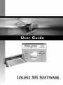
U se r G u id e
Ioline 301 Software
User Notice
Trademarks
Ioline is a trademark of Ioline Corporation. Other product names, logos, designs, titles, words or phrases
mentioned within this publication may be trademarks, service marks, or trade names of Ioline Corporation or other entities and may be registered in certain jurisdictions including internationally.
Ioline Disclaimer
IOLINE CORPORATION PROVIDES THIS MANUAL “AS IS” WITHOUT WARRANTY OF ANY KIND,
EITHER EXPRESS OR IMPLIED, INCLUDING BUT NOT LIMITED TO THE IMPLIED WARRANTIES
OR CONDITIONS OR MERCHANTABILITY OR FITNESS FOR A PARTICULAR PURPOSE. IN NO
EVENT SHALL IOLINE, ITS DIRECTORS, OFFICERS, EMPLOYEES OR AGENTS BE LIABLE FOR ANY
INDIRECT, SPECIAL, INCIDENTAL, OR CONSEQUENTIAL DAMAGES (INCLUDING DAMAGES
FOR LOSS OF PROFITS, LOSS OF BUSINESS, LOSS OF USE OR DATA, INTERRUPTION OF BUSINESS
AND THE LIKE), EVEN IF IOLINE HAS BEEN ADVISED OF THE POSSIBILITY OF SUCH DAMAGES
ARISING FROM ANY DEFECT OR ERROR IN THIS MANUAL OR PRODUCT.
Limit of Liability Statement
It is the responsibility of the operator of the software to monitor performance and maintain it in proper
working condition by following the instructions in this User Guide. It is the responsibility of the operator of the cutter to follow all safety precautions and warnings that are described in this User Guide and
the 300 / 350HF System User Guide. Ioline Corporation is not responsible for injuries that may occur as
a result of unsafe use. Ioline Corporation is not responsible for substandard operational performance as
a result of failure to maintain the software or cutter as described in this User Guide and the 300 / 350HF
System User Guide. Ioline makes no warranty regarding the accuracy of the documentation or system.
© 2003-2006 Ioline Corporation. All rights reserved. This manual may not be copied, photocopied, reproduced, translated, transmitted or converted to any electronic or machine-readable form in whole or in
part without prior written approval of Ioline Corporation.
Service and Support
If you require assistance with an Ioline product, your local Ioline dealer or authorized service center is
ready to help. Support information is also available 24/7 on the Ioline Web site—or you may contact Ioline
directly
Ioline Corporation
14140 NE 200th Street
Woodinville, Washington 98072 U.S.A.
Ioline Customer Service Department
Monday through Friday
700 A.M. - 500 P.M. U.S. Pacific Time
Voice: 1.425.398.8282
Fax: 1.425.398.8383
[email protected]
www.ioline.com
Part Number (File): 107647 Rev. 4
Ioline 301 Software
User Gu i d e
Images & Illustrations
Figure 1.
Figure 2.
Figure 3.
Figure 5.
Figure 4.
Figure 6
Figure 7
Figure 8.
Figure 9.
Figure 10.
Figure 11.
Figure 12.
Figure 13.
Figure 14.
Figure 15.
Figure 16.
Figure 17.
Figure 18.
Figure 19.
Figure 20. Figure 21. Figure 22. Figure 23. Figure 24. Figure 25. Figure 26. Figure 27. Figure 28. Figure 29. Figure 30. Figure 31. Figure 32. Figure 33. Figure 34. Figure 35. Figure 36. Figure 37. Figure 38. Figure 39. Figure 40. Figure 41. Figure 42. Figure 43. Figure 44. The 300 / 350HF System installation screen.................................................... 15
301 Software parallel hardlock key..................................................................... 16
Rear view of computer ........................................................................................ 16
301 Software Main Window ............................................................................ 17
301 Software icon ................................................................................................. 17
Select import options prior to importing the design file ............................ 18
Loading a file into 301 Software ........................................................................ 18
301 Design Window ......................................................................................... 19
301 Design Window function buttons defined .............................................. 20
301 Design Setup Window ........................................................................... 21
Send to Cutter Window ................................................................................ 23
Choose file format to save the cut file ............................................................ 24
Example of saving a file in Tajima .TFD format ............................................... 25
Save Design File Status Window . ............................................................. 27
Create Stitches Window ............................................................................... 29
301 Registration Window Functions ........................................................... 31
Port Setup Window ......................................................................................... 32
301 Stitch Editor Blue Toolbar Mode, design level functions ............. 34
301 Stitch Editor Black Toolbar Mode, segment level functions ....... 35
Descriptions of stitch types ................................................................................ 37
Creating stitches ................................................................................................... 38
Stitch density values ............................................................................................. 38
Select a Port Window ....................................................................................... 39
Ready to Send Window ................................................................................. 39
Removing the stitch “island” in the letter “A” ............................................. 40
Design after removing stitch “islands” . ............................................................ 40
Select the first stitch you wish to edit ............................................................. 41
The bottom stitches will align in an arc after editing . .................................. 41
The completed edit .............................................................................................. 41
Choose the layer that contains the outline to cut ........................................ 42
Use these buttons to set registration points .................................................. 43
Design outline with Registration points defined ........................................ 43
Setting the Origin for digitizing on the cutter .............................................. 44
Choosing a digitizing point on the cutter ........................................................ 44
Digitizer point displayed on screen ................................................................... 45
Turn the cut layer ON before sending to the cutter ................................... 45
Completed cut using registration ...................................................................... 45
Export/Save Window for HP/GL file ........................................................... 46
Import Barudan design files ................................................................................ 47
Save Barudan design files ..................................................................................... 47
CorelDRAW!® main screen ................................................................................ 49
Letters before and after welding and addition of a contour ....................... 50
The weld roll up .................................................................................................... 50
The contour rolls up ............................................................................................ 51
Table of Contents
Table of Contents
Foreword
Introduction ............................................................................................................................... xiii
301 Software Features ........................................................................................................ xiii
Chapter 1
Assembly & Set-up
Chapter 2
Overview
Chapter 3
Editing Designs
Install Ioline Software ........................................................................................................... 15
Installing the Hardlock Key ................................................................................................. 16
Launching 301 Software ...................................................................................................... 17
Opening a File ........................................................................................................................ 17
Design Window ..................................................................................................................... 19
Functions ................................................................................................................................. 20
Design Setup Window ......................................................................................................... 21
Sending a Cut File to the Cutter ....................................................................................... 23
Pause Cutting ......................................................................................................................... 23
Cancel a Cut .......................................................................................................................... 24
Save File (and Create Sew Disk) ........................................................................................ 24
Create Sew Disk / Output Window ................................................................................. 24
Sew Disk / Output Options ............................................................................................... 25
Save Design File Status Window ........................................................................................ 27
Create Stitches Window ..................................................................................................... 28
Registration Window Functions ........................................................................................ 31
Port Setup ............................................................................................................................... 32
Edit Design ............................................................................................................................. 32
Help .......................................................................................................................................... 32
Exit ........................................................................................................................................... 32
Using Edit Design .................................................................................................................. 33
Blue Toolbar Mode ................................................................................................................ 33
Black Toolbar Mode .............................................................................................................. 33
Edit Design Functions ........................................................................................................... 34
Blue Toolbar Mode ................................................................................................................ 34
Black Toolbar Mode ............................................................................................................. 35
Chapter 4
Chapter 5
xii
Index
Tutorials
Create Stitches ...................................................................................................................... 37
Stitch Guide . .......................................................................................................................... 37
Hints for Choosing Stitch Types ........................................................................................ 38
Density Values for Zigzag and Satin columns .................................................................. 38
Creating a Sew Disk ............................................................................................................. 39
Cutting a Design ................................................................................................................... 39
Using Edit Design ..................................................................................................................... 40
Remove a Block of Stitches ................................................................................................ 40
Edit Individual Stitches ......................................................................................................... 41
Using Registration ................................................................................................................... 42
Cutter Preparation ............................................................................................................... 42
Open 301 Software .............................................................................................................. 42
Prepare 301 Design Setup .................................................................................................. 42
Create Registration Points . ................................................................................................ 43
Digitize Points from the Cutter ......................................................................................... 44
Prepare the Cutter ............................................................................................................... 44
Digitize the Points ................................................................................................................. 44
Send Adjusted File to Cutter . ............................................................................................ 45
Saving Registration Points in a File .................................................................................... 46
Special Cases .............................................................................................................................. 46
Importing Barudan® FMC (.dat) Files ............................................................................... 46
Saving Barudan® FMC (.dat) Files ...................................................................................... 47
Exporting .DXF files from Adobe® Illustrator® ............................................................... 48
Importing .DXF files into 301 ............................................................................................ 48
Using CorelDRAW!® to Make a Design ......................................................................... 49
Creating a Design ............................................................................................................ 49
Welding Letters ..................................................................................................................... 50
Creating a Contour .............................................................................................................. 50
Saving the File ........................................................................................................................ 51
End Notes
Service & Support ................................................................................................................... 53
Getting Help ............................................................................................................................... 53
Customer Service .................................................................................................................... 54
Your Comments Are Requested ....................................................................................... 54
Before you contact Support ............................................................................................... 55
The FCC Wants You to Know ............................................................................................. 56
Booklet ................................................................................................................................... 56
Foreword
Introduction
301 software is designed to work with Ioline cutters. It imports and
digitizes stitch or design files for cutting graphics on the cutter and
exports sew disks for use by most popular embroidery machines.
For more information about Ioline cutters, please see the 300 / 350HF
System User Guide.
301 Software Features
n
Interfaces with Ioline cutters.
n
Imports major embroidery system designs including Tajima .
DST, Melco .EXP, Toyota .10o and Barudan .DAT formats.
n
Imports designs created in CorelDRAW!® (HP/GL .PLT) and
makes embroidery sew disks.
n
Nests and cuts multiple copies of pattern outlines, minimizing
material waste.
n
Includes placement, tack-down, zigzag & satin stitches. Choice
of stitch width, density and overlap.
n
Edit Stitches: Move, convert jump to trim, add or delete lock
stitches. Change thread color.
i
Note
Make sure 301 software is installed
as shown in the Installation section.
This page intentionally left blank.
xiv
Chapter 1
Assembly & Set-up
Install Ioline Software
1.
Insert the software CD-ROM into the PC’s CD-ROM drive.
2.
The installation should start automatically. If it does not, go
to Start Menu>Run. Click on Browse and choose the CDROM drive (usually D:\). Select iosetup.exe then Open and
Run.
3.
Follow the self-guided installation instructions to install the
Ioline Control Center, 301 Software, Acrobat® Reader, and all
manuals. See Figure 1.
Figure 1. The 300 / 350HF System installation screen.
4.
A window may appear asking to install ‘Hardlock Drivers’.
Answer ‘Yes’ to all questions.
5.
Restart the computer if requested.
16
Ioline 301 Software User Guide
Installing the Hardlock Key
301 Software requires a hardlock key (or Dongle). Without it, the
software will not work.
The hardlock key is packaged in the Accessory Kit. It plugs into a PC
printer (LPT) or USB port. (See Figures 2 and 3.)
Ioline 301
hardlock
“dongle”
Back of
computer
Figure 2. 301 Software USB hardlock key.
Figure 3. Rear view of computer showing correct installation of the parallel
hardlock and printer cable
Chapter 2
Overview
Launching 301 Software
1.
Locate then double click on the Ioline 301
sun icon. (By default, this icon is placed on
the desktop after installation.)
2.
The Main Window will appear (Figure 5.)
Figure 4. 301
Software icon.
Figure 5. 301 Software Main Window.
Opening a File
1.
Choose a file type. 301 Software can import major embroidery
system designs, including Tajima .DST, Melco .EXP, Toyota
.10o and Barudan .DAT formats. The program also supports
CorelDraw!® HP/GL .PLT format.
2.
Check the Import Options by pressing the button and reading
the descriptions (Figure 6).
18
Ioline 301 Software User Guide
Figure 6: Select import options prior to importing the design file.
3.
Use the center file window to locate the folder and file to import. The default folder is C:\Ioline\Data (Figure 7).
Figure 7: Loading a file into the 301 Software.
Chapter 2: Overview 19
4.
Click on the file name to import. If the file is not shown make
sure that the file type and folder location are correct.
5.
Click on Load Import File.
6.
The Design Window will appear (Figure 8).
Design Window
Y-axis ruler
(carriage motion)
Scroll bars
Design Window functions
(see Figure 9)
X-axis ruler
(Tray motion)
Figure 8: 301 Design Window.
Ioline 301 Software User Guide
20
Functions
Figure 9: 301 Design Window buttons.
Zoom
Enlarges (+) or reduces (-) the view. Each increment
is twice/half size.
All
Zooms the display to fit the entire design.
Cutter Display
Shows the cut outline
Stitch Display
Shows embroidery stitches created with the
Create Stitches function.
Stitch Count
The approximate number of stitches in the displayed design. Active when embroidery stitches
are displayed under the Stitch Display.
Show Jumps
When in Stitch display, shows all PenUp (needle
up) movement as dashed lines.
Show Reg. Pts.
Displays registration points in the Design Window if
they are available.
Pan
Recenters the screen over the cursor when the left
mouse button is clicked in the Design Window.
Single Step
Displays the vectors in the design file one at a
time. Clicking the button displays the next vector.
Design Setup
Displays all of the adjustable settings that modify
the design.
Send to Cutter
Sends the current design to the cutter. Ensure that
the cutter is in Start (green LED) mode with material loaded and blade properly adjusted.
Save File
Saves the stitch file in an embroidery machine or
HP/GL .PLT format.
Create Stitches
Allows the user to create and modify stitches.
Registration
Opens the Registration Window for digitizing
and cutting around a preprinted image.
Print
Sends the current view to a Windows printer.
Port Setup
Configures the PC port connected to the cutter.
Edit Design
Opens the Stitch Editor application for manual
stitch editing.
Help
Provides assistance for 301 software.
Close
Closes the Design Window.
Chapter 2: Overview 21
Design Setup Window
Figure 10: 301 Design Setup Window.
Needle down after first
stitch following jump(s)
In rare cases, uncheck this box to
remove unwanted cuts where a
thread is located.
Remove extra pen up
movement (jumps)
Combines multiple jumps into a
single jump. This cleans a design of
jumps that trigger automatic thread
trimmers.
Remove segments less than
Combines small vectors into
smoother segments to improve cutting quality and reduce cutting time.
Close gaps less than
Repairs shapes that are not continuous. Gaps affect cutting quality and
stitch output.
Rotate
Rotates base design.
Mirror
Mirrors base design.
Ruler Type
Change default display units.
Design Margins
Sets the white space border around
the tray edge.
Copies
Displays multiple copies of the
design so that more than one design
is cut at a time. Select Maximum
to fill the tray. Set Copy Count and
Horizontal and Vertical counts for
the desired number of copies.
22
Ioline 301 Software User Guide
Margins Between Copies
Control the space between copies.
Material Dimensions
Changes the dimensions of the
displayed cutting area to match the
material size.
Cutter Size
Change cutting area for different
cutter models.
Color Setup
Toggles one or more layers on or
off for cutting or editing stitches.
Enables user to rename layers.
Included Layers
Displays the list of layers imported
from the plot file.
Cut Order
Change the numbering in this
column to determine the order each
layer is cut when the file is sent to
the cutter.
Stitch Order
Change the numbering in this
column to determine the order each
layer is stitched when the sew disk
is created.
Pause Between Layers
When enabled, the cutter will stop
cutting between each consecutive
layer and enter Stop (red keypad
light) mode. The user must press the
Start/Stop key (green keypad light)
on the cutter to resume cutting.
Show ALL Colors
This immediately displays all layers
in the design. Turn off layer zero to
get rid of unwanted jump stitch cuts.
Show First Color Only
Turns on only the first layer and
hides all other layers.
Kiss Cut ALL
This is a specialty function for “KissCutting”. Turn Kiss Cut ALL on if
you intend to cut multiple layers
that must be on top of one another
after a cut.
Preview
Opens a preview window that
displays the results of changes in
Design Setup.
Setup Buttons
Save and Recall custom settings
with these buttons. Pressing the
Default button will reset all settings
to the factory default.
Apply
Applies the changes in the Design
Setup Window without closing it.
Chapter 2: Overview 23
Sending a Cut File to the Cutter
Pressing the Send to Cutter button displays the window shown in
Figure 11. Pressing Send will transmit the design displayed in the
Design Window to the cutter.
i
Note
Make sure that the carriage
and material are in the proper
position and that an origin is set
by pressing “Set Origin” on the
keypad (LED is green).
i
Note
If registration data are set with
the Registration feature, a
check mark will appear in the box
Adjust output using registration
data and the 301 will adjust the
cut file to the registration points.
Unchecking this box will send the
cut file without adjustment for
registration.
Figure 11: Send to Cutter Window.
Before Sending...
Always load the cutter and make test cuts to determine the correct
settings before sending any files. See the Adjusting Blade Exposure
and Force sections of the 300 / 350HF System User Guide for more
details.
Send the file directly from the 301 software following the directions
later in this manual or;
From the Ioline Control Center Software:
1.
From the menu bar select File, Send Cut/Plot File.
2.
Either enter the path and file name of the cut or select the correct location from the directory\file lists in the dialog box. For
example, the path might be:
C:\Ioline\Data\<filename>.plt
3.
Select OK.
Pause Cutting
1.
Press the Start/Stop key to place the cutter in Stop mode (red
LED).
2.
When cutting is interrupted, the carriage and material can be
moved with the keypad Arrow keys.
3.
Press the Start/Stop key to resume cutting. The cutter will
return to the original cutting position and continue plotting
where it stopped. The keypad LED will change from red to
green.
Caution
Make sure that the blade
tip is not touched while
examining a cut. This
could damage the blade and cause
inaccurate cutting.
24
Ioline 301 Software User Guide
Cancel a Cut
i
Note
Use the HP/GL (.PLT) format to
save the design outline file for
cutting later or to keep registration data with the file.
1.
Press the Start/Stop key to place the cutter in Stop Mode (red LED).
2.
Cancel the cut by clicking on the Abort button in the Send File
Window. Note: If this step is skipped the cut will continue when a
new origin is set with the Set Origin key.
3.
Press the Set Origin key to make the signcutter delete the cut
data it has already received but has not yet plotted.
Save File (and Create Sew Disk)
The Save File Window will appear when the Save File button is
pressed (Figure 12). Choose a format to save the sew data.
Figure 12: Choose file format to save the cut file.
Create Sew Disk / Output Window
1.
Choose a format. The Export Window will appear (See Figure 13).
2.
Choose the path and file name.
3.
Check the appropriate boxes in the Options list (see below).
4.
Press Continue with Export.
5.
The Save Design File Status Window appears.
Chapter 2: Overview 25
Figure 13: Example of saving a file in Tajima .TFD format.
Sew Disk / Output Options
TFD Label (Tajima Only):
Includes a file description in the
header portion of a Tajima file.
Automatic Centering:
If checked, the center of the design
will be at current origin of the embroidery head. Design will start at
the center and return to the center.
If this item is not checked, the first
segment of the design will begin at
the current origin and the embroidery head will stop at end of last
stitch segment.
Move before changing color:
If checked, the embroidery machine
will jump to the start of the new
color/section then change to the
new color (i.e. change needles after
moving to the new section). If unchecked, the embroidery machine
will change to the new color (change
needles) before jumping to the start
of the new (color) section.
Extra stitch after jumps:
Check to force the embroidery machine to needle down at the start of
the first stitch following a jump.
Trim-jump, minimum:
If a single jump stitch exceeds the
length specified here, it will change to
a trim jump.
Trim 3 / Trim 5:
The number of consecutive jumps
that will trigger an embroidery machine trim command.
i
Note
See the Special Cases section in
Tutorials for information about
using Barudan file formats.
26
Ioline 301 Software User Guide
Color/Stop added to end:
If this item is checked, a color change
record will be appended to the end
of the design. Commonly used with
Barudan FMC (set to first needle of
color sequence so it is ready for sewing the design again).
Move Pantograph After
Placement Stitch:
The Pantograph (sometimes called a
hoop) holds the material and moves
in x and y directions. If this field is
checked, after the placement outline
is sewn the embroidery head will
move just beyond the top or bottom
border of the outline and 1 color
change will occur. At this stage, the
applique material can be placed.
The operator has to program the
machine to stop at the first color
change encountered.
Use (2) color stop:
If checked, the procedure above
will include (2) consecutive color
records. The embroidery machine
operator may prefer this option
(program embroidery machine
to stop when 2 consecutive color
records are encountered).
Save Registration Points
(HP/GL Only):
Saves the location of the registration points in the output file. The
points will reappear when the file is
opened and are reusable.
Include All Layers
(HP/GL Only):
Saves registration points from all
layers in the output file.
Chapter 2: Overview 27
Save Design File Status Window
After pressing Continue with Export the Save Design File Status
Window will appear. The following are displayed:
n
A summary of the output file statistics.
n
Print Specifications function. Choose Portrait or to make a hard
copy of the export file statistics. The options customize the
report.
Figure 14: Save Design File Status Window.
28
Ioline 301 Software User Guide
i
Note
The term polygon refers to an
enclosed vector shape.
Create Stitches Window
Placement Stitch
Makes an outline of the polygon to
aid placing the piece.
Tack-down Stitch
An indented stitch that tacks the letter or shape down to the fabric.
Indent (Tackdown)
Specifies the amount the tack-down
stitch is indented from the polygon.
Bean Stitch This stitch resembles tiny beans.
Three stitches are placed back
and forth between two points and
stitched in a single line.
Indent (Bean)
Specifies the amount the bean stitch
is indented from the polygon.
B3/B5
“B3” and “B5” define the number of
back and forth bean stitches.
Stitch
Fragmentation Length
Lock Stitch at
Start/End
Breaks all stitches which exceed the
entered length into smaller pieces.
Double Lock
Makes the lock stitch a star-shaped,
5-stitch pattern instead of the triangular 3-stitch pattern. This setting is
recommended to improve durability.
Convert Outline to
Embroidery Resolution Outlines are adjusted so coordinates
are all evenly divisible by 4. This
helps ensure that column stitch end
points align more accurately (accurate overlap with placement stitch
endpoint’s).
A triangular sequence of 3 very
small stitches are added to the start
and end of each group of stitches.
This secures (locks) the stitching to
prevent unraveling.
Eliminate Protruding Stitches Improves Zigzag stitching on some
shapes.
Tackdown/Bean: Segment Reduction Removes small segments in the
Tackdown and Bean stitches to
improve output.
Close Polygons
Closes gaps smaller than 1mm that
were left in a polygon and smooths
stitching of vectors that do not
exactly share end points.
Chapter 2: Overview 29
Figure 15: Create Stitches Window.
Group Internal
Polygons
Regroups internal polygons (shapes)
with their respective external
polygons so that the entire group is
processed at once (the default). Left
unchecked, shapes process in the
order of the original import file.
Simple Overlap Logic
Sets the stitch overlap direction to the
outside for internal polygons. When
left unchecked (the default), the overlap on internal polygons falls to the
inside. (See note in side column.)
Eliminate Duplicate Polygons Duplicate polygons (exact same
shape and segment count) are eliminated to improve processing.
Setup Buttons
Use these buttons to Save and Recall
custom settings. Pressing the Default
button will reset all settings to the
factory default.
Zigzag Column Stitch
Puts a zigzag stitch around a polygon.
Density (Zigzag)
See the Stitch Density Table (*Figure 22, in Chapter 4) for stitch/cm
values.
i
Note
Internal polygons—shapes that lie
within the boundaries of another
polygon—have a default overlap
direction toward the inside (away
from the external polygon). For
some designs, you may want
to change the direction to the
outside (toward the external
polygon) using Simple Overlap
Logic. For example, to prevent
the white space in the center of a
capital letter “A” from closing up.
30
Ioline 301 Software User Guide
Overlap (Zigzag)
Percentage of the column width that
overlaps the outline. A 50% overlap
places half the stitch on one side of
the outline and half on the opposite
side.
Contour
Creates a smoother appearance by
graduating the transition between
zigzag columns.
Clip Ends
Removes the first and last stitch.
Handy for removing protruding
stitches.
Satin Column Stitch
Places a satin stitch around the polygon.
Density (Satin)
See the Stitch Density Table (*Figure 22, in Chapter 4) for stitch/cm
values.
Overlap (Satin)
Percentage of the column width that
overlaps the outline. A 50% overlap
places half the stitch on one side of
the outline and half on the opposite
side.
Add Corner Buffer Points
Smooths the corner transitions. Also
referred to as mitred corners.
Short Stitching in Corners
Lessens the density of stitch endpoints in corners.
Extend Corners
Sharpens corners. Leave unchecked
to blunt corners.
Chapter 2: Overview 31
Registration Window Functions
Zoom
Enlarges (+) or reduces (-) the view.
Each increment is twice/half size.
Pan
Recenters the screen over the cursor
when the left mouse button is
clicked in the Design Window.
Design Setup
Displays adjustable design settings
(e.g. margins, active layers, etc.).
Send to Cutter
Sends the design to the cutter. Ensure that the cutter is in Start (green
LED) mode with material loaded
and the blade properly adjusted.
Registration: Set Point 1
Puts 301 Software in Registration
Point Entry Mode. The first registration point is placed where the left
mouse button is clicked. A small R1
appears to show the R1 point.
Registration: Set Point 2
Same as above except an R2 marks
the location of the second point.
Snap to Endpoint
Automatically finds the nearest vector endpoint when
placing the registration point.
Digitize: Set Point 1
Puts 301 Software in Digitize Point
Entry Mode. Manually move the
carriage and tray so that the digitize
tool is positioned over the design in
exactly the same place the Registration Point (R1) is displayed on
screen. Press the Start/Stop button
on the keypad to set the digitized
point. D1 will appear when the
point is received by the 301.
Digitize: Set Point 2
The same as above except D2 marks
the location of the second point.
Clear Digitized Points
Deletes all digitized points displayed on the screen.
Exit Registration
Closes Registration and sends the
registration data to the display
window. Check Show Reg. Points
to display registration points.
Status Window
Displays the Registration Mode and
instructions for the next step.
Coordinates Window
Shows the x-y coordinate location of
the cursor.
Figure 16: Registration Window.
32
Ioline 301 Software User Guide
Port Setup
Choose the PC serial port where the
cutter is connected.
Flow Control
Digitizing Mode should be selected
for proper communication. This is the
default setting.
Figure 17: Port Setup Window.
Edit Design
Opens the Edit Design Window to allow precise adjustment of individual stitches. See Chapter 3 to learn about the basic functions of
the Edit Design application. The Tutorial chapter at the back of this
manual step-by-step instructions on using the Edit Design functions.
Help
Opens the 301 Help File.
Exit
Closes the Design Window and returns to the Main window.
Chapter 3
Editing Designs
Using Edit Design
The Edit Design application enables you to make subtle changes to
individual stitches in a file. Figure 18 outlines its basic functions. For a
more complete demonstration of basic stitch editing, see the Chapter 4.
There are two editing levels available within Edit Design, each identified by the color of the toolbar.
Blue Toolbar Mode
Permits changes at the overall design level, such as rotating or mirroring a design. This is the toolbar that appears when Edit Design is
selected under the Design Window.
Black Toolbar Mode
Permits stitch modifications at the segment level, also known as Black
Toolbar Mode. Click the Edit button on the Blue Toolbar, then click
on a stitch that you’d like to edit. 301 will display the Black Toolbar
and permit you to edit stitches.
34
Ioline 301 Software User Guide
Edit Design Functions
Figure 18. 301 Stitch Editor Blue Toolbar Mode, design level functions.
Blue Toolbar Mode
Design Level Functions
Close
Edit
Zoom
ESC
Move
Preferences
Color
Rotate
Mirror
Cut Paste
Remove
Clean
X
Help
Undo Options
Closes the editor, returns to the Design Window.
Edit at segment level (Black Toolbar Mode).
Adjust display view of design.
Escape from the current task.
Move entire design.
Cross hair type, ruler type, etc.
For color change or background.
Dual direction in single degrees or 10x.
Mirror either horizontally or vertically.
Cut the highlighted portion of the design.
Paste buffer contents.
Removes extra jumps, extra jumps & trims or
small stitches.
Removes extra jumps, trims and small stitches.
exit Editor.
Displays online Help.
Undo previous changes.
To edit jumps and trims.
Chapter 3: Editing Designs 35
Figure 19. 301 Stitch Editor Black Toolbar Mode, segment level functions.
Black Toolbar Mode
Segment Level Functions
Color
Exit
Change> Trim Change> Jump
Change> Run Change> Single
Cut Remainder
Move Remainder Zoom
Paste
< and >
<< and >>
>C and <C
>J and <J
X
START Block
End- Move
End- Cut
Grab
All Lock
Unlock
Double
Del
Current Record
Change the stitch color.
Returns to Blue Toolbar Mode.
Change selected to a Trim Stitch.
Change selected to a Jump Stitch.
Change selected to a Run Stitch.
Change selected to a Single Satin Stitch.
Cut unhighlighted portion of segment.
Move unhighlighted portion of segment.
Adjust display view of design in (+) or out (-).
Paste unhighlighted portion of segment.
Move selected segment forward and backward.
Fast Forward and Fast Backward.
Forward and Backward to next Color Change.
Forward and Backward to next Jump Stitch.
exit Segment Level of Editor.
Identify start of section for editing.
Identify end of section for moving.
Identify end of section for deletion.
Select segment between previous and next jump.
Selects all segments within a group (i.e. both
“islands” in “B”).
Put a Locking Stitch at start and/or end of a
selected group.
Remove Locking Stitches from selected group.
Split the current segment in the middle.
Delete the current segment.
Displays the segment number, stitch type and
relative and absolute coordinates.
Row 1 (e.g. “160 Run: 30” ): Shows the segment
number (in order from start), and the type of
segment. Outline, Tack-down, and Bean stitch
36
Ioline 301 Software User Guide
segments are referred to as Run i.e. run-stitch;
Satin and Zigzag stitches are referred to as Sngl
i.e. single segments.
Row 2: Shows the relative coordinates of the
segment (vector).
Row 3: Shows the absolute coordinates of the
endpoint of the current highlighted segment.
The coordinate display will change when the
mouse pointer is moved, to show the current
mouse position.
Chapter 4
Tutorials
Create Stitches
1.
Open a design file.
2.
Click on the Create Stitches button. See Figure 20 for samples
and an explanation of the 5 stitch types.
3.
Select your desired stitch type(s) (Figure 21).
4.
Click on OK when finished.
5.
The design will appear with the stitches imposed over the
outline.
Placement
Stitch
Tack-down
Stitch
Bean
Stitch
Zigzag
Stitch
Satin
Stitch
Stitch Guide
Placement: An outline stitch of the applique. Used to aid the
placement of the cloth pieces on the garment.
Tack-down: A rough stitch to initially apply the cloth design to
the garment. Holds the cut pieces in place during
the embroidery process.
Bean:
A decorative stitch consisting of 3 or 5 stitches between 2 points. This stitch has a thicker appearance
than the standard running stitch.
Zigzag:
Light-density stitch with adjustable width and offset.
The lower stitch count usually results in a lower cost.
Satin:
A high-density stitch with, adjustable width and
offset. High stitch count results in high quality, but
also often higher cost.
Figure 20. Descriptions of stitch types.
38
Ioline 301 Software User Guide
Figure 21. Creating stitches.
Hints for Choosing Stitch Types
The following table shows the Density Values for Zigzag and Satin
columns:
Density
Per Centimeter
Percentage
1
10
10%
2
10.5
11%
3
11
11%
4
12
12%
5
12.5
13%
6
13.5
14%
7
14
14%
8
15
15%
9
17
17%
10
18
18%
11
20
20%
12
22
22%
13
25
25%
14
29
29%
15
33
33%
16
40
40%
17
50
50%
18
67
67%
19
100
100%
20
133
133%
Figure 22. Stitch density values.
Chapter 4: Tutorial 39
Creating a Sew Disk
1.
Choose Save File. Click on the output type required by the
stitching machine.
2.
Enter a file name and location for the stitch file. Choose Continue with Export.
3.
If a file parameter window appears, adjust the settings as necessary. Click Continue.
Cutting a Design
1.
Use the keypad Arrow keys to position the Table and carriage so
that the blade tip is over the lower right corner of the material.
2.
Press Set Origin on the keypad to
obtain a green keypad light.
3.
Click on the All button under
Zoom in the upper left corner of
the screen.
4.
Click on CUTTER Display.
5.
Click on Port Setup (Figure
23). Verify that the current port
matches the port to which the
cutter is physically connected to.
See the cutter User Guide for help
identifying the COM port. Click
OK.
Figure 23. Select Port Window.
6.
Click on Send to Cutter. Make
sure that Adjust output using
registration data is checked if
the design was digitized. Click
on Send. The cutter will begin
the cut sequence. Wait until
this is finished.
7.
Remove (weed) the excess material. Remove the cut letters.
Put them aside to embroider
later.
Figure 24. Ready to Send Window.
i
Note
Fabrics.plt requires a 5- x
11-inch piece of cloth. Load the
cutter with the 5-inch edge of the
material on the long (Y) edge of
the tray.
40
Ioline 301 Software User Guide
Using Edit Design
Remove a Block of Stitches
This exercise will demonstrate how to remove a block of stitches
from a stitch file with the Edit Design features.
Remove the Stitches
1.
Load fabrics.plt into 301 Software. Add Outline and Zigzag
stitches to the file. These steps are described above.
2.
Press the Edit Design button.
3.
Click the Edit button in the Blue Toolbar, then click any of
the zigzag stitches in the triangle in the center of the “A” (the
“island”). The Black Toolbar will appear (Figure 25).
Island
Figure 25. Removing the stitch “island” in the letter “A”.
4.
Click on Grab. The whole block of stitches will change color
and the Blue Toolbar will appear.
5.
Click on Cut. The stitches on the “island” will disappear. Only
the outline stitch will
remain.
6.
Repeat the previous
steps to remove the
outline stitch. Repeat
this process for the
“B” and the “R”.
7.
The design will look
like Figure 26 after the
edits are complete.
Figure 26. Design after removing stitch “islands”.
Chapter 4: Tutorial 41
Save the File
1.
Exit the Stitch Editor by choosing the Exit Editor button. Click
on Yes to save the changes made during the session. Choose
No when asked to continue editing the design.
2.
The standard 301 software screen will appear. Click Save File
to save the file in the format required by the embroidery machine.
Edit Individual Stitches
The process for editing individual stitches includes creating a stitch
arc from the flat stitches generated by the 301 Software.
Figure 27. Select the first stitch
you wish to edit.
Prepare to Edit
1.
Reload fabrics.plt into the 301 Software. Recreate the stitch file.
Start the Stitch Editor. These steps are described above.
2.
Press the Zoom button. Click in the editing window near the
center of the “A” with the left mouse button (Left click).
3.
Choose Level 3. If required, use the scroll bars to reposition the
image so that the stitches in Figure 27 are visible.
Modify the Stitches
1.
Choose the Edit button. Left click on the stitch shown in Figure
27.
2.
Click on the small square at the end point of the selected stitch
with the right mouse button (Right click). Moving the mouse
will reposition the stitch end point.
3.
Drag the end point so that it looks like the Figure 28.
4.
When the stitch end point is positioned properly, Left click on
the mouse to release it in the new position.
5.
Use the Right and Left Arrow keys in the Black Toolbar to
select the next stitch in the row.
6.
Repeat Steps 2 through 4 for the remaining stitches in the row.
7.
Repeat the process for the stitches in the bottom row of the
“island” in the “A”. Use Figure 29 as a guide.
Save the File
1.
Exit the Stitch Editor by choosing Exit then click on the Close
button. Click on Yes to save the changes made during the session. Choose No when asked to continue editing the design.
2.
The standard 301 software screen will appear. Click Save File
to save the file in the format required by the embroidery machine.
Figure 28. The bottom stitches
will align in an arc after editing.
Figure 29. The completed edit.
42
Ioline 301 Software User Guide
Hint
If the Force range is changed
in the Ioline Control Center,
make sure that the new settings
are sent to the cutter using the
Permanent button.
Using Registration
Registration features allow users to cut or plot around a previously
created patch, chenille design, label, or printed design. All that is
required is a design file that includes the design outline for digitizing and a contour layer for cutting around the pattern. Ensure the
file is in a format that the 301 can read. Please follow the instructions
below for best results. Use the cutter User Guide for guidance using
the cutter.
Cutter Preparation
Hint
The blade tip must clear the
material when it is not cutting.
Cutting accuracy is affected if it
does not.
1.
Prepare the 300/350HF tray with the proper adhesive sheet.
For example, use a high tack sheet for cutting scrim felt.
2.
Lay material onto tray adhesive sheet and smooth out any
bubbles or bumps.
3.
Adjust cutting force and blade exposure for the material to be
cut by performing a series of test cuts.
Open the 301 Software
1.
Open the Ioline 301 Software by double clicking on the sun icon
on the desktop or in Start>Programs>Ioline.
2.
Browse to the Design file folder.
3.
Click on a File Type button, i.e. HP/GL (.PLT).
4.
Open the file by double clicking on the name in the file list.
5.
The Design Window will appear.
Prepare the 301 Design Setup
1.
Click on Design Setup.
2.
Under the heading
Color Setup, select the
color/layer that shows
the pattern for registration that the 300 will cut
around. Verify that Kiss
Cut All is selected. This
feature is checked by default. See Figure 30.
3.
i
Note
Fabrics.plt requires a 5x11-inch
piece of cloth. Load the cutter with the 5-inch edge of the
material on the long (Y) edge of
the tray.
Select OK.
Figure 30. Choose the layer that contains the outline to cut.
Chapter 4: Tutorial 43
Create Registration Points
Registration points are features used to align the pattern/plot that
you wish to cut or plot around. Greater distance between the registration points will result in greater accuracy in the adjusted plot/cut
file. Points should be chosen that are easily selectable from the pattern (sharp corners, rather than curves).
1.
Click on the Registration button. The 301 enters Registration
Mode.
2.
Under Registration Points,
click on Set Point 1 (Figure
31).
3.
Position mouse pointer over
desired Registration Point
and click the left mouse
button. Consecutive clicks
of the left mouse button will
re-select the coordinate.
4.
Click the right mouse button
to accept first registration
point (Figure 32).
5.
Under Registration Points,
click on Set Point 2.
6.
Position mouse pointer over the desired Registration Point and
click left mouse button.
7.
Click the right mouse button to accept second registration point
(Figure 32).
Figure 31. Use these buttons to
set registration points.
Figure 32. Design outline with Registration points defined.
Hint
Check the Snap selection box to
easily select vector endpoints.
44
Ioline 301 Software User Guide
i
Note
Set the plot origin properly to
ensure accurate cutting around
the object (Figure 32).
Digitize Points from the Cutter
These steps require that the shape be positioned on the tray and ready
to digitize. The sample file 2color.plt is shown for this demonstration.
Prepare the Cutter
1.
Remove blade holder.
2.
Install the Registration Tool.
3.
Use the Arrow keys to position the carriage and table so that
cut/plot file will be in the positive x and y directions from the
origin (Figure 33).
4.
If the keypad light is red, press the Set Origin button. If not,
press the keypad Start/Stop button until the keypad light turns
red, then press the Set Origin button. The light will turn green.
Position the registration tool to the right and
below the area to be cut as
shown. Press the Set Origin button on the keypad.
X
Y
Figure 33. Setting the Origin for digitizing on the cutter.
Digitize the Points
1.
In 301 Software, under
Digitize Points, click on
Set Point 1. Two clicks
may be required. The LED
light on the keypad will
turn red.
2.
Using the cutter keypad
Arrow keys, position the
carriage and tray so that
the registration tool tip
is over the First Digitize
Point that corresponds
to the registration point
selected above (Figure 34).
Hint
Turn the speed knob all the way
down (counterclockwise) for precise carriage and tray movement.
Digitize Points must be carefully
selected to ensure accuracy of
the adjusted file.
Figure 34. Choosing a digitizing point
on the cutter.
3.
Press Start/Stop key on keypad.
4.
301 Software will display the new digitize point on-screen (Figure 35) and will change the LED light to green.
Chapter 4: Tutorial 45
5.
In 301 Software, click on
Set Point 2 under Digitize
Points. (Two clicks may be
required.) The LED light
on the keypad will turn
red.
6.
Repeat Step 2 for the second digitizer point.
7.
Press Start/Stop key on the
keypad.
8.
301 Software will display
the second digitize point
on-screen as a DZ to
RZ (Figure 35) and will
change the LED light to
green.
Figure 35. Digitizer point displayed
on screen.
Send Adjusted File to Cutter
1.
Select Design Setup. Under the heading Color Setup, check the
color box(es) for only the
layers you want to cut. All
colors with checked boxes
selected will be cut. For the
2color.plt file, check only
color 1 (the contour color);
uncheck color 0 (Figure 36).
2.
Select Send to Cutter. The
box next to Adjust output
using registration data
should be checked. If not,
file will not be adjusted
using registration data.
3.
Remove the registration
tool and install the blade
holder. Force and blade
exposure must be properly
adjusted before sending.
See the cutter User Guide
for more information.
4.
Click on Send. See Figure
37 for completed cut.
Figure 36. Turn the cut layer ON before sending to the cutter.
Hint
Digitize points are reusable to
save time when using registration to Kiss Cut or cut multiple
contours of the same design.
Figure 37. Completed cut using registration.
The steps described in Digitize Points from Cutter and Send Adjusted File to Cutter should be
repeated for each shape that requires registration. If the file did not cut
completely through the material, make test cut(s) to readjust the blade
exposure and/or force. Once properly adjusted, press the Repeat button to recut or replot the adjusted file.
Caution
Pressing the Set Origin
then Repeat keypad buttons will shift the starting
location of the cut and could ruin
the output.
46
Ioline 301 Software User Guide
Saving Registration Points in a File
It is possible to store the registration points that are created for a
design.
1.
Select Exit Registration or click on
X in upper right
corner of display
window.
2.
Click the Save File
button.
3.
Select HP/GL
plotter (.PLT). Export window will
open (Figure 38).
4.
Select the drive/
directory for the
exported file.
5.
Type a file name.
6.
Ensure that the following check boxes are checked:
• Include Registration Points
• Include all Layers
7.
Click on Continue with Export.
Figure 38. Export/Save window for HP/GL file.
Special Cases
Importing Barudan® FMC (.dat) Files
Barudan® (.DAT) format may exist on an MS-DOS disk or on a Barudan® FMC (CP/M format) disk. If you wish to import/export from a
Barudan® FMC disk, you must first copy the files from the Barudan®
FMC disk to path C:\Ioline\Barudan\.
Important: This procedure requires that Software 22 disk for
Barudan® FMC by Sydex is present in the C:\Ioline subdirectory. Contact Ioline Customer Service for more information.
1. Place the Barudan® FMC disk into drive A: or B:.
2.
Press Import Options in the Main 301 Window.
3.
Choose Copy A or Copy B to move all .DAT files from the disk
to C:\Ioline\Barudan (Figure 39).
4.
After copying files from FMC disk, exit the options window
and select Barudan® (.DAT).
5.
Select to import from C:\Ioline\Barudan.
6.
Select the design file name (with .DAT extension) from those
listed.
Chapter 4: Tutorial 47
Figure 39. Import Barudan design files.
Saving Barudan® FMC (.dat) Files
Saving a Barudan® .DAT file onto a CP/M formatted floppy disk requires an initialization step beforehand. This step is NOT necessary
if the .DAT files are saved onto an MS-DOS formatted floppy disk.
Important: This procedure requires that Software 22 disk for
Barudan® FMC by Sydex is present in the C:\Ioline subdirectory. Contact Ioline Customer Service for more information.
1.
Choose the Barudan® format from the Save File dialog window
(Figure 40).
2. Place a floppy disk in the A: or B: disk drive.
3.
Press the Initialize... button for the correct drive.
4.
When the process is complete, press the Copy File to Drive...
button to finish the export.
Figure 40. Save Barudan design files.
48
Ioline 301 Software User Guide
Exporting .DXF files from Adobe® Illustrator®
The 301 software will import designs exported from Adobe® Illustrator® in the .DXF file format.
1.
Finish the design in Adobe® Illustrator®.
2.
Choose Export from the Illustrator® File menu.
3.
Enter a file name.
4.
In the File Format window, choose AutoCAD .DXF.
5.
Choose OK.
6.
A window will appear with export options. Choose the following:
• ACAD Version: R14/LT98/LT97
• Number of Colors: 256
• Raster File Format: BMP
• Check Box Export Selected Art Only: no preference
• Check Box Alter Paths for Appearance: no preference
• Check Box Outline Text: no preference
7.
Choose OK.
Importing .DXF files into the 301
1.
Setup the 300 and 301 as explained in the Quick Start Guide.
2.
Start the 301 software by double clicking on the program icon.
3.
At the main screen, press the AutoCAD DXF button.
4.
Choose the file in the Import File Name window.
5.
Press the Load Import File button.
6.
The file is imported into the 301 Design Window.
Chapter 4: Tutorial 49
Using CorelDRAW!®
to Make a Design
This exercise will illustrate the fundamentals of using CorelDRAW!®
to create a design, welding letters together, creating a contour (or
background layer), and exporting the file in HP/GL format for use in
the 301 Software.
These are general steps so may work differently on other versions of
CorelDRAW!®. Please contact Corel Corporation for more information on the use and features of CorelDRAW!®.
Creating a Design
1.
Start CorelDRAW!®.
2.
Click on the Text tool, then click the cursor anywhere near the
lower lefthand corner of the page.
3.
Type the word “Cougars”. Highlight the word with the mouse,
or by pressing Ctrl and Shift, then the left Arrow on the keyboard (Figure 41).
4.
Go to the Font List and select Brush Script MT. “Cougars”
will change to a scripted font with all the letters overlapping
but not joined. Resize the letters by typing “200” in the Font
Size List.
Pick
Tool
Arrange
Menu
Effects
Menu
Text
Tool
Figure 41. CorelDRAW!® main screen.
i
Note
Look at the outline and notice
how the individual letters are
not actually connected to one
another. The lines on the screen
are the lines the cutter will cut.
Welding (Figure 40) will connect
the lines.
Remove Color
Color Palette
50
Ioline 301 Software User Guide
Figure 42. Letters before welding and addition of a contour (left) and with a
contour after welding (right).
5.
Click on the Pick Tool.
6.
In the Color Palette, Left click on the X which is usually the
top box. The image will go away.
7.
In the Color Palette, Right Click on the color of your choice.
The image will reappear as an outline only.
Welding Letters
1.
Click on “Cougars” with the Pick Tool. Go to the Arrange
menu. Click on Weld. A large black arrow will appear.
2.
With that arrow, click on
the “C” in “Cougars”.
The cut lines that are in
between the letters will
disappear. “Cougars” is
now one object instead of
seven (Figure 43).
3.
Click and drag the grips
(small-black squares
visible after selecting an
object) to make the object
the desired size.
Creating a Contour
i
1.
With “Cougars” selected,
open the Effects menu and
select Contour. The Contour roll up will appear.
2.
Check the box next to Outside and enter “.25” in the
Offset box. In the Steps
box, enter “1” (Figure 44).
Note
CorelDRAW!® version 7.0 has
a bug that will cause the welding
process, explained below, to fail. If
using version 7.0, please call Corel
at 800.772.6735 for help.
Figure 43. The weld roll up.
Chapter 4: Tutorial 51
Outline button
Figure 44. The contour rolls up.
3.
Click the Color Wheel tab in the Contour dialogue box. Click on
the Outline icon and select a color for the design (Figure 44).
4.
Click on Apply. This will create a 1/4” contour around “Cougars” in the selected color (Figure 45).
5.
Open the Arrange menu and select Separate. Click the mouse
somewhere on the empty page. This will deselect both “Cougars” and the new background design.
Saving the File
1.
Open the File menu. Select Export. Select PLT HP/GL Plotter
File as the file type. Name the file “Cougars,” and click OK.
Accept the default settings for the export process.
2.
The file is now ready for importing into the 301 Software. Different colors are treated as different layers in the 301 software
so the Cougars.plt file will open into the 301 with two layers.
52
Ioline 301 Software User Guide
This page intentionally left blank.
Chapter 5
End Notes
Service & Support
Ioline has many years of experience working with sports and decorative apparel professionals. Feel free to contact us if you have questions—or to share information.
Getting Help
Ioline is committed to providing the highest quality service and
support to its customers. If you need assistance with an Ioline 300 or
350HF System, a number of resources are available:
1.
First, refer to this User Guide for answers to your specific questions.
2.
Many detailed troubleshooting and repair issues are listed
in the 300 / 350HF Systems Service Manual, available upon
request from Ioline Customer Service.
3.
Consult the support section of the Ioline Web site:
4.
www.ioline.com
For additional assistance, contact your local dealer or Ioline
Customer Service. Contact information is listed under Customer
Service in this chapter.
Any warranty servicing of this product not specifically described
in this manual must be authorized in writing by Ioline Customer
Service. You may obtain service by calling or faxing Ioline Customer
Service. The technicians will help you determine the nature of the
problem. If factory repair is necessary, you will receive a RMA (Return Material Authorization). Please gather the information indicated on the next page before contacting Ioline or your dealer.
1.
When returning a machine, carefully package the equipment
in its original container or packaging equivalent. You may
purchase shipping containers from Ioline by contacting Ioline
Customer Service. Ioline is not responsible for any damage
due to inadequate or improper packaging.
2.
Carefully wrap and secure all items in the shipping container to
prevent damage. Seal the container and note the RMA number
near the address block.
54
Ioline 301 Software User Guide
3.
Ship the container using FED-EX or another approved carrier.
COD shipments ARE NOT ACCEPTED. An Ioline representative will contact you prior to the start of work with an estimate
of repair cost. All repairs are warranted for 90 days.
Customer Service
Ioline Corporation is committed to providing quality service and
support to our customers. If you need assistance with an Ioline product, contact your local dealer or Ioline authorized service center. You
may also contact:
Ioline Customer Service Department
Monday through Friday
7:00 A.M. - 5:00 P.M. U.S. Pacific Time
Voice: 1.425.398.8282
Fax: 1.425.398.8383
[email protected]
www.ioline.com
Your Comments
Are Requested
Ioline Corporation is interested in comments on our documentation
and products. Please send corrections or suggestions to:
Ioline Corporation
14140 NE 200th Street
Woodinville, WA 98072 USA
Voice: 1.425.398.8282
Fax: 1.425.398.8383
[email protected]
www.ioline.com
This User Guide is provided for informational purposes only. The
contents are subject to change without notice, and Ioline Corporation assumes no responsibility for any errors that are contained
herein. No part of the 300 or 350HF Systems User Guide may be
copied, disseminated, or distributed without the express written
consent of Ioline Corporation.
Chapter 5: End Notes 55
Before you contact Support…
Please gather the following information about your printer before
contacting Ioline or your dealer for technical support:
Name:
Company
Name:
Phone
Number:
Fax:
E-mail:
Model:
Serial
Number*:
Date of
purchase:
Dealer:
Type of media
& ink used:
Type of
Computer:
Type of
design software:
New software
or peripherals:
Service history:
56
Ioline 301 Software User Guide
The FCC Wants You to Know...
This equipment generates and uses radio frequency energy and, if
not installed and used properly (in strict accordance with manufacturer instructions), it may cause interference to radio and television
reception. Operation is subject to the following two conditions: (1)
This device may not cause harmful interference, and (2) this device
must accept any interference received, including interference that
may cause undesired operation. If this equipment does cause interference to radio or television reception - which can be determined
by turning the equipment off and on - you are encouraged to try to
correct the problem by one or more of the following measures:
n
Use only shielded interface cables.
n
Reorient the receiving antenna.
n
Relocate the host computer with respect to the receiver.
n
Move the host computer away from the receiver.
n
Plug the host computer into a different outlet so that the host
computer and receiver are on different branch circuits.
If necessary, consult the dealer or an experienced radio/television
technician for additional suggestions. How To Identify and Resolve
Radio-TV Interference Problems, a booklet published by the Federal
Communications Commission, is a helpful reference. Please contact
the FCC to request a copy:
www.fcc.gov
Document stock number: 004-000-00345-4
This booklet is available from:
U.S. Government Printing Office
Washington, D.C. 20402
Index
Symbols
Block xii, 35, 40
Remove 40
10o files xiii, 17
Blue Toolbar Mode x, xi, 33, 34, 35, 40
Design Level Functions 34
301 Software vii, ix, x, xi, 17, 15, xii, 16, 30, xiii, 17, 18, 40,
41, 42, 44, 45, 49, 51
Design Window x, xi, 19, 20, 23, 30, 31, 34, 42, 48
Edit design functions 34
Icon 17
Launching 17
Opening a file 17–19
C
Cancel 24
Carriage 19, 23, 30, 39, 44
A
Carriage motion 19
Accessory Kit 16, 57
Change
Jump 35
Run 35
Single satin stitch 35
Trim 35
Acrobat® Reader 15
Clean 34
Add Corner Buffer Points 29
Clear digitized points 30
Adhesive sheet 42
Clip Ends 29
Adjusting blade exposure 20, 23
Close 20, 34
Adjust output using registration data 23, 39, 45
Close gaps 21, 28
Adobe® Illustrator® 48
Close gaps less than 21
Appliqué
Placement of 28
Close Polygons 28
Abort 24
Apply 22
Arrow keys 23, 39, 41, 44
Automatic Centering 25
Color 35
Change xiii, 26, 34
Move before changing 25
Color/Stop added to end 26
Color Setup 22, 42, 45
Color stop 26
B
Computer 55
Barudan x, xiii, 17, 18, 25, 26, 46, 47
FMC files 46–47
Software 22 disk 47
Contour 29
Creating 50–51
Layer 42
Bean stitch 37
Control Center 15, 23, 42
Black Toolbar Mode x, xi, 33, 35
Segment Level Functions 35
Coordinates Window 31
Blade exposure 23, 45
Blade holder 44, 45
Continue with Export 39
Copies 22
Copy Margins 22
CorelDRAW!® x, xiii, 49–51
Corners 29
Extend 29
Mitered 29
Short stitching 29
Dongle 16
Multiple, daisy chaining 16
Create Sew Disk 24–31
Double 35
Create Stitches x, xi, 20, 28, 29, 37
Double Lock 28
Create Stitches Window 28–29
DST files xiii, 17
Current Record 35
DXF files xii, 48
Customer Service 53, 54
Contact information 54
Cut Remainder 35
Cut remainder 35
Cutter display 20, 21, 30, 31, 33, 34, 35, 44, 45, 46
Cutter Size 22
Cutting 39
Avoid cutting a thread 21
Cancel 24
Multiple layers 22
Pausing 23
Send a cut file to the cutter 23, 45
Send to cutter 20
Specify number of copies 22
Cutting area 22
Display 20, 21, 30, 31, 33, 34, 35, 44, 45, 46
E
Edit 34
Edit Design 20, 31, 33–35, 40–41
At design level 34
Design Level Functions 34
Segment level 35
Edit stitches xiii
Emb 35
Embroidery systems xiii, 17, 20, 22, 25, 26, 37, 41
Compatible file formats xiii
Embroidery system settings. See Sew Disks, Output
options
ESC 34
D
Exit xi, 30, 31, 35, 41, 46
DAT files xiii, 17, 46, 47
EXP files xiii, 17
Del 35
Export x, 24, 27, 39, 46, 48, 51
Density x, xii, xiii, 28, 29, 37, 38
Values 38
Extend Corners 29
Exit Registration 30
Extra stitch after jumps 25
Design Center 25
Design Level Functions 34
Design Margins 21
Design Setup 20–21, 30
Apply changes 22
Cutting area 22
Dimensions 22
Preview on-screen 22
Specify number of copies 22
Design Setup Window 21
Design software 55
F
FCC 56
File formats xiii, 17, 24
FMC xii, 26, 46, 47
Fonts 49
Creating a Contour 50
Welding 50
Design Window x, xi, 19, 20, 23, 30, 31, 34, 42, 48
Buttons 20
Functions 19, 20
Force 23, 42, 45
Digitize xii, 30, 44, 45
Points 30, 44
G
Digitize Point 44
Digitizing software. See 301 Software
Dimensions 22
Gaps 21, 28
Grab 35, 40
Group Internal Polygons 28
Cutting 45
Preview 22
Renaming 22
Save registration points from 26
Selecting 42
Show all 22
Toggle on/off 22
Turning off 22
H
Hardlock Drivers 15
Hardlock Key xi, 16
Letters. See Fonts
Help xi, xii, 20, 31, 34, 53
Loading a file 18
Hoop
Moving to place appliqué 26
Lock 28, 35
Double Lock 28
Selected group 35
Unlock 35
HP/GL x, 17, 20, 24, 26, 42, 46, 49, 51
Lock Stitch at Start/End 28
I
LPT port 16
Illustrator®. See Adobe® Illustrator®
Import 17–19, 46, 48
M
Import options 17, 46
Main Window x, 17
Include All Layers 26
Margins 21, 22
Around tray edge 21
Between copies 22
Indent 28
Insert 35
Installation 15–16
Interference problems 56
Ioline Corporation 54
Material xiii, 20, 22, 23, 26, 30, 39, 42, 45
Material Dimensions 22
Media 55
Melco xiii, 17
Mirror 21, 34
J
Move 34
Jumps xiii, 21, 22, 25, 35
Extra stitch after 25
Trim xiii, 25
Viewing on-screen 20
Move Pantograph After Placement Stitch 26
K
Move before changing color 25
Move Remainder 35
N
Needle down 21
Key. See USB key
Needle down after first stitch following jump(s) 21
Kiss cut 22, 42, 45
Needle up 20
Kiss Cut ALL 22
Nest xiii
L
O
Layer
Contour 42
Creating in CorelDraw!® 49–51
Cut multiple 22
Opening a file 18
Options 34
Origin 23, 24, 25, 44
Outline Running Stitch 28
Remove extra pen up movement (jumps) 21
Outline stitch 28, 37, 40
Remove segments less than 21
Output Window 24
Repair 53, 54
Overlap xiii, 28, 29
Repeat 45
Return Material Authorization (RMA) 53
P
Pan 20, 30
Rotate 21, 34
Ruler units 21
Parallel hardlock key x, 16
S
Paste 34, 35
Satin Column Stitch 29
Pause 23
Satin stitch xii, xiii, 29, 35, 37, 38
Placement of appliqué 37
Save Design File Status Window 27
Placement stitch xiii, 26, 37
Save File xi, 20, 24, 39, 41, 46, 47
PLT files xiii, 17, 20, 24, 42, 46
Save Registration Points 26
Polygon 28
Internal 28
Segment
Cut 35
Move 35
Split. See Double
Pantograph. See Hoop
Port
Setup 20, 31
Preferences 34
Preview 22
Print 20
Specifications 27
Printer port 16
Segment Level Functions 35
Send to Cutter x, 20, 23, 30, 39, 45
Service 53
Under warranty 53
Set Origin 23, 24, 25, 44
Set Point 30, 43, 44, 45
R
Settings
Default 22
Recalling 22
Saving 22
Radio frequency 56
Setup Buttons 22, 28
Registration x, xi, xii, 20, 23, 26, 30, 31, 42, 43, 44, 46
Create Registration Points 43
Cutter Preparation 42
Exit 30
Set Point 1 30, 43
Set Point 2 30, 43
Status Window 31
Sew disk xi, xiii, 24, 25, 39
Create 24
Output Options 25
Save 20
Registration functions 30–31
Clear digitized points 30
Set Point 1 30
Set Point 2 30
Show First Color Only 22
Registration Mode 31
Simple Overlap Logic 28
Registration points x, 20, 23, 26, 31, 43, 46
Saving to a file 26
Single Step 20
Registration Tool 44
Registration Window x, xi, 20, 30
Remove 34
Block of Stitches 40
Short Stitching in Corners 29
Show ALL Colors 22
Show Jumps 20
Show Reg. Pts. 20
Snap selection box 43
Snap to Endpoint 30
Software. See 301 Software, Control Center or Embroidery systems
Apparel design software 55
speed 44
Tack-down Running Stitch 28
Start/Stop 23, 24, 30, 44, 45
Tack-down stitch xiii, 28, 37
Start/Stop key 23, 24, 44, 45
Tajima x, xiii, 17, 25
START Block 35
Tech Support 53, 54
Statistics 27
Test cuts 23, 42
Status Window x, xi, 24, 27, 31
TFD x, 25
Stitch density x, xiii, 29, 37, 38
Thread
Changing color xiii
Stitch Display 20
Stitch Editor x, 20, 34, 35, 41
Stitches
Adding xiii
Bean stitch 37
Block of xii, 35, 40
Choosing 38
Clip ends 29
Close gap 28
Creating 20, 28
Delete lock stitches xiii
Density xii, 28, 29, 38
Edit 41
Extra stitch after jumps 25
Fragmentation length 28
Lock 28
Locking stitch 35
Moving xiii
Outline running stitch x, 20, 24, 26, 28, 29, 37, 40, 42, 43,
49, 50
Overlap 28, 29
Placement 26, 37
Placement stitch 26
Remove 40
Satin stitch x, xii, xiii, 20, 21, 22, 25, 28, 29, 33, 35, 37, 38, 39,
40, 41
Stitch Guide 37
Tack-down 28
Tack-down running stitch 28, 37
Zigzag xii, 28, 37, 38, 40
Contour 29
Zigzag stitch xii, 28, 37, 38, 40
Toyota xiii, 17
Tray motion 19
Trim xiii, 25
Trim-jump 25
Troubleshooting
Radio-TV interference 56
Tutorial. See Chapter 4
U
Undo 34
Unlock 35
USB port 16
Use (2) color stop 26
V
Vector segments
Close gaps 21
Smoothing 21
Snap to endpoints 43
Stitch file. See Sew disk
Stitch Fragmentation Length 28
Stitch overlap xiii, 28, 29
Stitch types 37
Stitch width xiii
Stop Mode 24
Support 53, 53–56
Contact information 54
Ioline Web site 53
Warranty 53
Sydex 46, 47
W
Warranty viii, 53
Weed 39
Welding xii, 49, 50
X
X 34, 35
T
X-axis 19
Y
Y-axis 19
Z
Zigzag Column Stitch 28
Zigzag stitch xii, xiii, 28, 29, 37, 38, 40
Zoom 20, 30, 34, 35, 39, 41
All 20