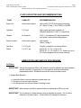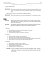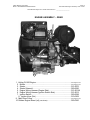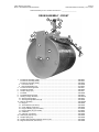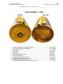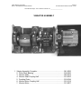
1
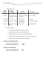
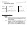
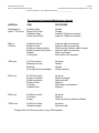
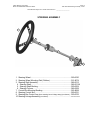
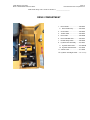
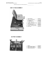
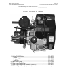
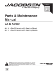
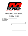
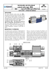
PARTS & SERVICE MANUAL
MODEL 1450/3000/4000
Document: 1450/3000/4000 Parts & Service Manual Rev. 1.5
Covers Serial Number Range:
018-XC14CGH1YG-00018 thru ____________________
SOLD & SERVICED BY
Calder Brothers Corporation
Model: 1450/3000/4000 Steel Drum Roller
Page 1
1450-3000-4000 Table Of Contents 1.0.doc
TABLE OF CONTENTS
ITEM
PAGE
Roller Service & Operation Section................................................... 3
Steering Assembly ............................................................................ 15
Drive Compartment ........................................................................... 16
Seat & Tank Assembly ...................................................................... 17
Battery Assembly .............................................................................. 17
Engine Assembly - Front ................................................................... 18
Engine Assembly - Rear.................................................................... 19
Drum Assembly - Front ..................................................................... 20
Drum Assembly - Rear ...................................................................... 21
Vibrator Assembly ............................................................................. 22
Calder Brothers Corporation
Model: 1450/3000/4000 Steel Drum Roller
Page 2
1450-3000-4000 Notes 1.0.doc
NOTES
Calder Brothers Corporation
Model: 1450/3000/4000 Steel Drum Roller
Page 3
1450-3000-4000 Roller Service & Operation Section 1.0.doc
Serial Number Range: 438-J-14PHH1YG-02438 thru ____________________
IMPORTANT SAFETY INFORMATION
Most accidents involving roller maintenance are caused by failure to observe basic safety rules or
precautions. An accident can often be avoided by recognizing potentially hazardous situations
before an accident occurs.
Read and understand all safety precautions and warnings, before operating or performing
lubrication and maintenance on this roller.
WARNING:
IMPROPER OPERATION, LUBRICATION OR MAINTENANCE OF THIS
ROLLER CAN BE DANGEROUS AND COULD RESULT IN INJURY OR
DEATH.
WARNING:
DO NOT OPERATE THIS ROLLER UNTIL YOU READ AND UNDERSTAND
THE INSTRUCTIONS IN THE OPERATION SECTION OF THIS MANUAL.
WARNING:
DO NOT PERFORM ANY LUBRICATION AND MAINTENANCE ON THIS
ROLLER UNTIL YOU READ AND UNDERSTAND THE INSTRUCTIONS IN
THE MAINTENANCE SECTION OF THIS MANUAL.
SERVICE WARNING
Operating personnel must perform service checks regularly to be sure systems are in good
operating condition. If abnormal conditions are detected, inform maintenance personnel
immediately.
Check all systems for proper operation. Check chassis and all components for physical damage
and security of all fasteners and connectors.
Calder Brothers Corporation
Model: 1450/3000/4000 Steel Drum Roller
Page 4
1450-3000-4000 Roller Service & Operation Section 1.0.doc
Serial Number Range: 438-J-14PHH1YG-02438 thru ____________________
FLUID CAPACITIES AND RECOMMENDATIONS
FLUID
CAPACITY
RECOMMENDATION
Engine oil
Varies with engines
High quality CC/CD multi-grade lubricating
oil. Above 14 deg. F use 15W40 or 20W40.
Hydraulic
7 U.S gal
High quality anti-wear hydraulic oil
(Original equipment, Gulf C-3 torque fluid).
Grease
As required
N.G.L.I. consistency #2, high temperature,
anti-friction, bearing lubricating grease.
Engine coolant
Varies with engines
High quality
Above 14 deg. F
Gasoline
Diesel
3 ½ U.S gal
3 ½ U.S. gal
Regular, unleaded, non-alcohol blend.
above 40°, (5° C), use No. 2-D.
Below 40°, (5° C), use No. 1-D. Power loss up to
4% can be expected due to lower viscosity
LUBRICATION AND SERVICE PROCEDURES
Air Filters
IMPORTANT: Service the engine air filters only when the need is indicated by the air cleaner
service indicator, (if equipped), or in accordance with the preventative
maintenance decal. Excessive service will cause premature wear.
1. Engine Main Element
a. Unbuckle clips to remove element container end cap.
b. Pull gently to remove main element.
c. Use compressed air with an element-cleaning nozzle
IMPORTANT: Main element should be replaced after six cleanings or 500 hours use.
IMPORTANT: Do not attempt to clean element using a standard air nozzle. Do not strike
element on a hard surface. Either action will damage the element.
Calder Brothers Corporation
Model: 1450/3000/4000 Steel Drum Roller
Page 5
1450-3000-4000 Roller Service & Operation Section 1.0.doc
Serial Number Range: 438-J-14PHH1YG-02438 thru ____________________
2. Engine Safety Element
IMPORTANT: Do not remove safety element under heavy dust or blowing conditions (in the
field). Even slight amounts of dust entering the engine can lead to premature
wear.
Inspect safety element for contamination and physical damage.
IMPORTANT: When safety element is dirty, it should be replaced. Do not attempt to clean.
Battery
CAUTION:
BATTERY ELECTROLYTE IS A CAUSTIC ACID. KEEP IT AWAY FROM
SKIN AND EYES. IF CONTACT OCCURS, FLUSH THE AFFECTED AREA
WITH LOTS OF WATER.
CAUTION:
DISCONNECT GROUND CABLE FROM THE NEGATIVE BATTERY POST
BEFORE ATTEMPTING TO SERVICE OR REMOVE BATTERY.
1. Removal:
a. Disconnect ground (negative) cable from battery (-) terminal.
b. Remove battery retaining rod.
c. Disconnect positive cable from battery (+) terminal.
2. Cleaning:
a.
b.
c.
d.
Remove battery, following correct procedures.
Thoroughly clean terminals with a battery-cleaning tool.
Mix a paste solution of baking soda and water and apply to battery and terminals.
Rinse battery and roller area near battery liberally with water.
3. Installation:
a.
b.
c.
d.
Clean battery, following correct procedures.
Be certain battery area is clean and clear of debris.
Install battery and retaining rod.
Connect positive (+) cable to terminal.
CAUTION: DO NOT CONNECT NEGATIVE (GROUND) TERMINAL FIRST. ARCING
CAN OCCUR, POSSIBLY CAUSING SEVERE BURNS AND/OR BATTERY
EXPLOSION.
Calder Brothers Corporation
Model: 1450/3000/4000 Steel Drum Roller
Page 6
1450-3000-4000 Roller Service & Operation Section 1.0.doc
Serial Number Range: 438-J-14PHH1YG-02438 thru ____________________
e. Connect negative (-) terminal
4. Charging:
Connect charger leads to proper battery terminals then proceed according to charger
manufacturer's instructions.
5. Storage:
a. Remove and clean battery, following correct procedures.
b. Bring battery to full charge, following charger manufacturer's instructions.
c. Store in a cool dry place where there is no possibility of freezing.
NOTE: Check battery every 30 days during storage and return to full charge if necessary.
Engine and Engine Filters
1. Initial Break-In:
Proper break-in procedures are a must to realize maximum engine power output and
longest engine life. Engine should show noticeable power gain through the first 30
hours service. Power gain will continue until approximately 200 hours if properly
broken-in.
IMPORTANT: Do not operate engine above 3/4 throttle, for the first 25 hours.
IMPORTANT: Use full throttle only for short intervals during the first 25 hours.
IMPORTANT: Do not "lug" engine during the break-in period.
IMPORTANT: Replace the original oil and oil filters after the first 20 hours of operation.
2. Fuel Filters:
Both fuel filters are disposable.
CAUTION:
BOTH DIESEL FUEL AND GASOLINE ARE HIGHLY FLAMMABLE AND
EXPLOSIVE UNDER CERTAIN CONDITIONS. DO NOT SMOKE OR ALLOW
SPARKS OR OPEN FLAME WHEN HANDLING.
Calder Brothers Corporation
Model: 1450/3000/4000 Steel Drum Roller
Page 7
1450-3000-4000 Roller Service & Operation Section 1.0.doc
Serial Number Range: 438-J-14PHH1YG-02438 thru ____________________
To Change:
a) Stop engine. Wait 15 minutes for engine and surrounding parts to cool
before proceeding.
b) Unscrew and discard existing filters.
c) Fill new filter with clean fuel.
d) Lightly coat the seal ring with oil, then screw on filter until seal meets
flange.
e) Tighten an additional 1/2 to 3/4 turns by hand.
IMPORTANT: Do not over tighten.
3. Oil and Oil Filter Changing:
a)
b)
c)
d)
e)
f)
g)
h)
i)
Stop engine. Wait 15 minutes or engine oil to cool before proceeding.
Drain crankcase.
Unscrew and discard existing filters.
Fill new elements with fresh oil.
Lightly coat the seal rings with oil, and then screw on filters until seals
meet flanges.
Tighten an additional 1/2 to 3/4 turns by hand.
IMPORTANT: Do not over tighten.
Fill crankcase to correct level.
Start engine and run at low idle. Have an assistant visually check seal
areas for leaks.
Stop engine. Wait a few minutes, and then check engine oil level once
again.
Hydraulic System
Hydraulic Fluid Change:
a) Stop engine. Allow system pressure to drop and remove filler cap.
b) Remove suction hose and drain into appropriate container for disposal.
c) Remove hydraulic filter. Replace filter element and reinstall.
d) Replace fluid to approximately 1" from top of reservoir. Operate roller and recheck level.
e) Check visually for oil leaks.
Calder Brothers Corporation
Model: 1450/3000/4000 Steel Drum Roller
Page 8
1450-3000-4000 Roller Service & Operation Section 1.0.doc
Serial Number Range: 438-J-14PHH1YG-02438 thru ____________________
NOTE:
a)
b)
c)
d)
e)
Each roller should be thoroughly inspected after each use and during
maintenance cycle for:
Tightness of mounting bolts and attaching hardware on bearings, couplings, frame, etc.
Leaks, cracks and loose electrical and fluid fittings.
Malfunctioning indicators or controls.
Worn or damaged tires.
Cleanliness.
TROUBLESHOOTING
1. General:
•
Proper troubleshooting begins with an organized approach to the problem at hand. Begin
with investigation of the most probable cause, following the guidelines below.
•
Study the problem thoroughly before taking action!
•
Did warning signs precede the problem? If so, what were they? What would they indicate?
•
Is scheduled maintenance current on all parts and systems involved?
•
Has similar trouble occurred before? What action was taken at that time?
•
Can engine be operated without further damage?
CAUTION:
IF RUNNING INSPECTION MUST BE MADE, GET ASSISTANCE.
OPERATOR SHOULD REMAIN SEATED ON ROLLER THROUGHOUT
INSPECTION. SET PARKING BRAKE. MAKE SURE TRANSMISSION IS IN
NEUTRAL POSITION.
•
Check the most convenient things first.
•
Don't begin major work before checking all other possibilities.
•
Reconsider all known facts and clues before proceeding to more in-depth work.
•
Correct the basic cause.
Calder Brothers Corporation
Model: 1450/3000/4000 Steel Drum Roller
•
Page 9
1450-3000-4000 Roller Service & Operation Section 1.0.doc
Serial Number Range: 438-J-14PHH1YG-02438 thru ____________________
Remember, failure of a certain part may be caused by malfunction of another part or
system
2. Troubleshooting chart:
The troubleshooting chart lists problems that might be encountered in the operation of the
vehicle. The remedies listed may direct the repairman to a possible faulty component.
WARNING: THE TROUBLESHOOTING CHART AND PROCEDURES OUTLINED IN THIS
SECTION SHOULD NOT BE ATTEMPTED BY OTHER THAN EXPERIENCED
MECHANICS OR PERSONNEL UNDER THE DIRECT SUPERVISION OF AN
EXPERIENCED MECHANIC. FAILURE TO COMPLY MAY RESULT IN DAMAGE
TO EQUIPMENT AND/OR INJURY OR DEATH TO PERSONNEL.
A. Engine
For engine troubleshooting see charts indicating faults and recommended repair
procedures. Refer to engine Manufacturer's Operation and Maintenance Manual.
If your particular problem is not covered or you are unsure of what steps to take, contact
your dealer for assistance.
B. Transmission
1. Vehicle fails to move under power:
a)
b)
c)
d)
Inadequate oil level in hydraulic reservoir.
Control cable broken or loose.
Driveline mechanical failure.
Inadequate oil flow through transmission suction filter.
2. Vehicle moves in neutral:
a) Stroke control needs adjustment.
b) Control cable damage.
For detailed troubleshooting information on hydrostatic transmission, refer to Trouble Shooting
Manual, Sundstrand Hydrostatic Transmissions, available from a Sundstrand representative or
dealer.
Calder Brothers Corporation
Model: 1450/3000/4000 Steel Drum Roller
Page 10
1450-3000-4000 Roller Service & Operation Section 1.0.doc
Serial Number Range: 438-J-14PHH1YG-02438 thru ____________________
C. Electrical System
Engine
Status
Voltmeter
Reading
Indicates
Running
13.5 - 14 Volts
Normal Condition
Running
Less than 13.5 or
more than 14 Volts
Alternator or Regulator
Malfunction
Contact Dealer
Won't Start
12-12.5 Volts
Weak battery
Charge
Won't Start
Less than 12 Volts
Weak battery or
Defective Cell
Charge or Replace
Stopped
Excessive current
Draw
Short Circuit
Inspect System
To Correct
D. Hydraulic System
•
Thoroughly review description of hydraulic system.
•
Use logical steps to determine cause of malfunction.
•
Identify the function or functions that require troubleshooting.
•
If possible, trace malfunction to source: pump, control, motor or cylinder.
•
Determine pressure operating the function as specified:
HYDRAULIC SYSTEM PRESSURES
Priority circuit, Sundstrand pump:
Main circuit Sundstrand pump:
900psi
2500psi
HYDRAULIC SYSTEM FLOWS
Priority circuit, Sundstrand pump:
Main circuit, Sundstrand pump:
2gpm
8gpm
Calder Brothers Corporation
Model: 1450/3000/4000 Steel Drum Roller
Page 11
1450-3000-4000 Roller Service & Operation Section 1.0.doc
Serial Number Range: 438-J-14PHH1YG-02438 thru ____________________
(Actual flow determined by engine rpm’s)
Problem
Possible Cause
No Power or
Inadequate Power
Surging of
hydraulic items
To Correct
Worn or Malfunctioning pump or motor.
Repair or replace pump or motor.
Stuck relief valve cartridge.
Repair or replace.
Low system pressure caused by worn pump.
Repair or replace pump.
Air in system due to low level of oil,
cavitating pump, leaky fittings, pinched hose, etc.
Add oil, tighten fittings, reroute
hose(s).
Removal and Installation of Equipment
1. Preparation
WARNING: BEFORE PERFORMING INSTALLATION OR REMOVAL PROCEDURES,
THE FOLLOWING PRECAUTIONS MUST BE ADHERED TO IN ORDER
TO PREVENT POSSIBLE DAMAGE TO EQUIPMENT OR INJURY OR
DEATH TO PERSONNEL.
WARNING: TURN THE ENGINE OFF BY TURNING THE IGNITION SWITCH TO OFF.
DISCONNECT THE BATTERY CABLES BEFORE SERVICING THE
ENGINE START OR STOP CIRCUITS. DISCONNECTING BATTERY
NEGATIVE GROUND BEFORE REMOVING OR CONNECTING THE
POSITIVE BATTERY CABLE CAN PREVENT SHORT CIRCUITING OF
THE BATTERY BY TOOLS.
Calder Brothers Corporation
Model: 1450/3000/4000 Steel Drum Roller
Page 12
1450-3000-4000 Roller Service & Operation Section 1.0.doc
Serial Number Range: 438-J-14PHH1YG-02438 thru ____________________
Recommended Preventive Maintenance Intervals
INTERVAL
ITEM
PROCEDURE
Initial Break-In
(After 1st 50 hours)
Hydraulic Filter
Engine Oil & Filter
Hydraulic Leaks
Loose Nuts & Bolts
Change
Change
Inspect & Tighten as required
Inspect & Tighten as required
Daily or
10 hours
Hydraulic oil level
Engine oil level
Engine air cleaner system
Engine coolant level system
Radiator
Fuel system
Inspect & add as necessary
Inspect & add as necessary
Check service indicator and/or inspect
Inspect & add as necessary
Clean and inspect
Drain water from separator
100 hours
All 10 hour Items
Steering rod ends
Bearings
Tires (optional tow package)
As above
Grease
Grease
Check pressure
250 hours
All 100 hour items
Engine air cleaner
Engine crankcase
Engine oil filter
Fuel tank
Hydraulic filter
As above
Replace element
Drain and refill*
Replace*
Drain water and sediment
Replace*
500 hours
All 250 hour items
Fuel filters
Engine
As above
Replace
Have serviced by authorized Dealer
1000 hours
All 500 hour items
Hydraulic system
As above
Drain and refill
*Change after first 50 hours service, every 250 thereafter.
Calder Brothers Corporation
Model: 1450/3000/4000 Steel Drum Roller
Page 13
1450-3000-4000 Roller Service & Operation Section 1.0.doc
Serial Number Range: 438-J-14PHH1YG-02438 thru ____________________
MAULDIN
™
CALDER BROTHERS CORPORATION
(LIMITED) PRODUCT WARRANTY
Calder Brothers Corporation warr ants that the Roller under this program will be free from defects
in material and workmanship for a period of (12) tw elve months from date of installation. Written
notice of any claimed defect must be given to Ca lder Brothers Corporat ion within the warranty
period and within (30) thirty days a fter such defect is discovered. Liability under this warranty is
limited to replacing or repairing, at Calder Brothers Corporation’ s election, any part or parts
deemed defective after examinati on by Calder Brothers Corporat ion or an Authorized Service
Representative. Any roller or any of its parts returned by customer to Calder Brothers Corporation
or an Authorized Service Repr esentative via prepaid transportation and which is found to be
defective will be repaired or replaced and retur
ned to the customer via prepaid surface
transportation within the continental United States. Should any part be found not defective, Calder
Brothers Corporation or an Au thorized Service Representative may charge inspection and
handling to the customer.
EXCLUSIONS:
This warranty does not apply to routine wearable parts of the Mauldin roller such as seals, points,
plugs, hoses or similar items. This warranty does not extend to any ro ller or part replaced or
repaired under this warranty. This warranty does not cover any repair or replacement labor of any
part or parts found defective after examination by Calder Brothers Corpor ation or an Authorized
Service Representative. This warranty does
not apply to defects caused by casualty or
unreasonable use, including faulty repairs by
others and failure to provide reasonable and
necessary maintenance.
THIS WARRANTY SET FORTH HEREIN IS IN LIEU OF AND EXCLUDES ANY AND ALL
OTHER WARRANTIES, EXPRESSED OR IMPLIED, ARISING BY OPERATION OF LAW OR
OTHERWISE, INCLUDING, BUT NOT LIMI
TED TO, ANY IMPLIED WARRANTY OF
MERCHANTABILITY OR FITNESS FOR A PAR
TICULAR PURPOSE, AND CUSTOMER
WAIVES ANY OBLIGATION OF LIABILITY OF CALDER BROTHERS CORPORATION ARISING
IN TORT OR STRICT LIABILI TY IN TORT, OR FOR LOSS OR USE, REVENUE OR PROFIT
WITH RESPECT TO MAULDIN ROLLER AND/OR PARTS FOR ANY LIABILTIY OF CUSTOMER
TO ANY THIRD PARTY, OR FOR OTHER DI
RECT, INCIDENTAL OR CONSEQUENTIAL
DAMAGES.
Calder Brothers Corporation
Model: 1450/3000/4000 Steel Drum Roller
Page 14
1450-3000-4000 Notes 1.1.doc
NOTES
Calder Brothers Corporation
Model: 1450/3000/4000 Steel Drum Roller
Page 15
1450-3000-4000 Steering Assembly 1.0.doc
Serial Number Range: 438-J-14PHH1YG-02438 thru ____________________
STEERING ASSEMBLY
1
3
2
4
5
6
7
8
9
1. Steering Wheel.................................................................................. 050-0030
2. Steering Wheel Mounting Disk (Rubber) ........................................... 015-0074
3. Steering Shaft Assembly ................................................................... 082-0013
4. Steering Shaft................................................................................. 082-0013A
5. Steering Shaft Bushing................................................................... 050-0004
6. Steering Column............................................................................. 082-0008
7. Control Box Mounting Bushing.......................................................... 050-0068
8. Steering Control Box ......................................................................... 050-0031
9. Steering Box Control Arm (from steering box to linkage assy) (not shown)... 050-0032
10. Steering Linkage Assembly (not shown) .............................................. See Drum-Front
10
Calder Brothers Corporation
Model: 1450/3000/4000 Steel Drum Roller
Page 16
1450-3000-4000 Drive Compartment 2.0
Serial Number Range: 438-J-14PHH1YG-02438 thru ____________________
DRIVE COMPARTMENT
1.
Drive Handle............................. 083-0024
2.
1
4
11
2
3
Choke Cable............................. 050-0025
4.
Throttle Cable ........................... 050-0024
5.
Drive Cable............................... 050-0008
6.
Drive Cable Ball Joint ............... 030-0237
7.
Neutral Safety Switch ............... 020-0002
8.
Hydraulic Filter Assembly ......... 021-0001
9.
6
7
Hydraulic Filter Head ............ 021-0087B
10. Hydraulic Filter Element ........ 021-0002
11. Vibrator Valve ........................... 017-0005
5
12. Hydraulic Tank Sight Guide ...... See Tank Assy
8
12
Drive Handle Grip ................. 050-0334
3.
9
10
Calder Brothers Corporation
Model: 1450/3000/4000 Steel Drum Roller
Page 17
1450-3000-4000 Seat, Tank, Battery Assembly 1.1.doc
Serial Number Range: 438-J-14PHH1YG-02438 thru ____________________
SEAT & TANK ASSEMBLY
1
7
8
10
2
5
4
3
6
1. Seat Assembly........................... 050-0017
2. Water Tank Assembly................ 081-0029
3. Inspection Cap........................ 050-0026
4. Ball Valve................................ 017-0043
5. Water Tank Filter .................... 021-0059
6. Hydraulic Tank Breather Cap .... 050-0016
7. Fuel Tank (not shown) ................... 050-0027
8. Fuel Tank Cap (not shown) ........ 050-0188
9. Hydraulic Tank Sight Guide ....... 060-0068
10. Seat Stand ................................. 082-0079
9
BATTERY ASSEMBLY
3
4
1
2
1.
2.
3.
4.
Battery........................................ 020-0019
Battery Cable (Positive) ............. 020-0361
Battery Cable (Negative) ........... 020-0318
Battery Retaining Rod................ 093-0046
Calder Brothers Corporation
Model: 1450/3000/4000 Steel Drum Roller
Page 18
1450-3000-4000 Engine Assembly - Front 1.0.doc
Serial Number Range: 438-J-14PHH1YG-02438 thru ____________________
ENGINE ASSEMBLY – FRONT
1
2
6
5
3
4
8
1. Kohler CH18S Engine ....................................................................... 010-0275
2. Muffler ............................................................................................ 010-0302
3. Engine Oil Filter .............................................................................. 021-0026
4. Fuel Filter ....................................................................................... 021-0027
5. Main Drive Pump............................................................................... 011-0138
6. Drive Pump Control Arm ................................................................... 082-0021
7. Drive Pump Control Arm Ball Joint (not shown) ................................... 030-0237
8. Rubber Engine Mount (x4) (not shown)................................................ See Engine-Rear
Calder Brothers Corporation
Model: 1450/3000/4000 Steel Drum Roller
Page 19
1450-3000-4000 Engine Assembly - Rear 1.0.doc
Serial Number Range: 438-J-14PHH1YG-02438 thru ____________________
ENGINE ASSEMBLY – REAR
1
7
8
2
6
9
4
5
3
10
1. Kohler CH18S Engine ....................................................................... See Engine-Front
2. Muffler ............................................................................................ See Engine-Front
3. Starter............................................................................................. 010-0375
4. Starter Solenoid.............................................................................. 020-0085
5. Engine Wiring Harness (Engine Side) ............................................ 010-0312A
6. Engine Wiring Harness (Ignition Switch Side) ................................ 010-0312
7. Ignition Switch ................................................................................ 020-0088
8. Ignition Keys (Set) ....................................................................... 010-0209
9. Main Drive Pump............................................................................... See Engine-Front
10. Rubber Engine Mount (x4) (not shown)................................................ 050-0260
Calder Brothers Corporation
Model: 1450/3000/4000 Steel Drum Roller
Page 20
1450-3000-4000 Drum Assembly - Front 1.3.doc
Serial Number Range: 438-J-14PHH1YG-02438 thru ____________________
DRUM ASSEMBLY - FRONT
19
12
18
23
16
15
13 17
14
22
21
20
6
8
7
5
4
11
10
9
1
11
2
1.
3
Front Drum Assembly (1450)................................................................................................ 082-0014
Front Drum Assembly (3000)................................................................................................ 082-0015
Front Drum Assembly (4000)................................................................................................ 082-0016
2. Front Drum Shaft............................................................................................................... 083-0008
3. Drum Shaft Bearing (x4) ................................................................................................... 018-0001
4. Front Drum Mounting Frame ................................................................................................ 082-0017
5. Front Drum Scraper .............................................................................................................. 082-0018
6. Scraper Hanger (x2) ............................................................................................................. 083-0011
7. Front Mat .............................................................................................................................. 083-0009
8. Front Mat Mounting Frame ................................................................................................... 083-0027
9. Steering Linkage Assembly .................................................................................................. 082-0012A
10. Steering Linkage Rod........................................................................................................ 082-0012
11. Steering Linkage Ball Joint (x2)......................................................................................... 050-0009
12. King Pin Assembly................................................................................................................ 083-0003A
13. King Pin............................................................................................................................. 083-0003
14. Thrust Washer (not shown) ............................................................................................... 083-0002
15. Cover Washer (not shown) ............................................................................................... 083-0004
16. King Pin Bearing (x2) (not shown)..................................................................................... 018-0030
17. King Pin Race (x2) (not shown)......................................................................................... 018-0024
18. Castle Nut ......................................................................................................................... 083-0005
19. Cotter Pin (not shown) ...................................................................................................... 030-0202
20. Water Spray Pipe (Front)...................................................................................................... 083-0029
21. Scraper Spring (x2)............................................................................................................... 050-0006
22. Scraper Spring Retaining Washer (push-on) (x2) ................................................................. 030-0359
23. King Pin Dust Cover (not shown).......................................................................................... 050-0266
Calder Brothers Corporation
Model: 1450/3000/4000 Steel Drum Roller
Page 21
1450-3000-4000 Drum Assembly v2.0 doc
Serial Number Range: 438-J-14PHH1YG-02438 thru ____________________
DRUM ASSEMBLY – REAR
Left Side
5
Right Side
6
4
1
2
3
1. Rear Drum Assembly (1450/3000 Model) .................................................. 082-10200
Rear Drum Assembly (4000 Model) ........................................................... 082-102002
2. Drum Bearing ........................................................................................... See Drum-Front
3. Planetary ................................................................................................... 016-0056
4. Rear Mat .................................................................................................... 083-0010
5. Rear Mat Mounting Frame ......................................................................... 083-0028
6. Rear Drum Scraper.................................................................................... 082-0019
7. Scraper Hanger (not shown) (x2) ............................................................... See Drum-Front
8. Water Spray Pipe (Rear) (not shown) ........................................................ 083-0030
9. Scraper Spring (not shown) (x2) ................................................................ See Drum-Front
10. Scraper Spring Retaining Washer (push-on) (x2)....................................... See Drum-Front
Calder Brothers Corporation
Model: 1450/3000/4000 Steel Drum Roller
Page 22
1450-3000-4000 Vibrator Assembly 1.0.doc
Serial Number Range: 438-J-14PHH1YG-02438 thru ____________________
VIBRATOR ASSEMBLY
1
7
5
2
2
4
6
3
1. Vibrator Assembly Complete............................................................. 081-0025
2. Pillow Block Bearing .................................................................... 018-0002
3. Vibrator Shaft............................................................................... 092-0074
4. Vibrator Shaft Coupling Half ........................................................ 015-0033
5. Coupling Chain ............................................................................ 015-0044
6. Vibrator Motor Coupling Half........................................................ 015-0119
7. Vibrator Motor .............................................................................. 013-0007
Calder Brothers Corporation
Model: 1450/3000/4000 Steel Drum Roller
Page 23
1450-3000-4000 Notes 1.2.doc
NOTES
CALDER BROTHERS CORPORATION
(LIMITED) PRODUCT WARRANTY
Calder Brothers Corporation warrants that the Paver, Roller, Tank or Grader
under this program will be free from defects in material and workmanship for a
period of(12) twelve months from the date of installation. Written notice of any
claimed defect must be given to Calder Brothers Corporation within the warranty
period and within (30) thirty days after such defect is discovered. Liability under
this warranty is limited to replacing or repairing at Calder Brothers Corporation
election, any part or parts deemed defective after examination by Calder
Brothers Corporation or an Authorized Service Representative via prepaid
transportation for which is found to be defective, will be repaired or replaced and
returned to the customer via prepaid surface transportation within the United
States. Should any part be found not defective, inspection and handling may be
charged to the customer by Mauldin or an Authorized Service Representative.
EXCLUSIONS:
This warranty does not apply to routine wearable parts of the Mauldin machine
such as seals, points, plugs, hoses or similar items. This warranty does not
extend to any machine or part replaced or repaired under this warranty. This
warranty does not cover any repair or replacement labor or any part of parts
found defective after examination by Mauldin or an Authorized Service
Representative. This warranty does not apply to defects caused by casualty or
unreasonable use, including faulty repairs by others and failure to provide
reasonable and necessary maintenance.
THIS WARRANTY SET FORTH HEREIN IS IN LIEU OF AND EXCLUDES ANY
AND ALL OTHER WARRANTIES, EXPRESSED OR IMPLIED, ARISING BY
OPERATION OF LAW OR OTHERWISE, INCLUDING, BUT NOT LIMITED TO,
ANY IMPLIED WARRANTY OF MERCHANTABILITY OR FITNESS FOR A
PARTICULAR PURPOSE, AND CUSTOMER WAIVES ANY OBLIGATION OF
LIABILTY OF MAULDIN ARISING IN TORT OR STRICT LIABILITY IN TORT,
OR FOR LOSS OR USE, REVENUE OR PROFIT WITH RESPECT TO
MAULDIN MACHINE AND/OR PARTS FOR ANY LIABILTY OF CUSTOMER TO
ANY THIRD PARTY, OR FOR OTHER DIRECT, INCIDENTAL OR
CONSEQUENTIAL DAMAGES.
I have read and fully understand the warranty policy above.
Customer
CALDER BROTHERS CORPORATION
Witness
Calder Brothers Corporation
250 E Warehouse Ct.
Taylors SC, 29687
4amauldin.com
864-244-4800
Fax 864-244-5007