1
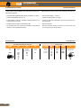
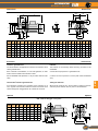
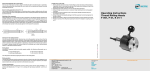
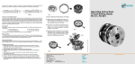
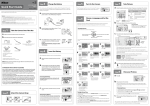
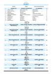
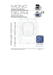
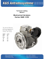
Technical catalog
Manual
Mechanical Variators
Series VAM / CHV
The series VAM and
CHV are identical but
they have different
names. See below:
VAM = CHV
018
02
037
05
075
10
15
20
22
30
40
50
K&S Antriebssysteme GmbH & Co. KG
Industriestraße 28a
21493 Schwarzenbek
Tel.: 04151 - 87 906-0
Fax: 04151 - 87 906-11
www.ks-antriebssysteme.de
RIDUTTORI
MOTOVARIATORI
COMBINATI
COMBINATION
MECHANICALGEARBOXES
VARIATORS
Indice
Index
Caratteristiche tecniche
Tecnical features
Designazione
Classification
Principio di funzionamento
Operating principle
Lubrificazione
Lubrication
Dati tecnici
Technical data
Simbologia
Symbols
Dimensioni
Dimensions
Accessori
Accessories
Options
Uso e manutenzione
Use and maintenance
Pag.
Page
K2
K2
K3
K4
K4
K4
K5
K5
K5
K6
VAM
Opzioni
CMM
VAM
Questa sezione annulla e sostituisce ogni precedente edizione o revisione. Qualora questa sezione non Vi sia giunta in distribuzione controllata, l’aggiornamento dei dati ivi contenuto non è assicurato. In tal
caso la versione più aggiornata è disponibile sul nostro sito internet www.transtecno.com
1112A
This section replaces any previous edition and revision. If you obtained
this catalogue other than through controlled distribution channels, the
most up to date content is not guaranteed. In this case the latest version is available on our web site www.transtecno.com
F11
K
CMM
VAM
MOTOVARIATORI
RIDUTTORI
COMBINATI
COMBINATIONVARIATORS
MECHANICAL
GEARBOXES
Caratteristiche tecniche
Technical features
I variatori epicicloidali a satelliti conici VAM hanno le seguenti caratteristiche principali:
VAM mechanical variator range has the following main features:
• Precisione nella regolazione della velocità, contenuta in ± 0.5/1%.
• Precise speed setting : ± 0.5/1%
• Campo di regolazione continuo 1:5.
• Continuous setting within 1:5 range
• Funzionamento continuo in entrambi i sensi di rotazione, con
entrata ed uscita concordi.
• Continuous CW and CCW rotation, synchronous input and output movement.
• Flangia di attacco motore in standard IEC B5.
• B5 IEC standards
• Le grandezze 018, 037 e 075 sono costruite con carcassa in
alluminio, le altre grandezze in ghisa.
• Die-cast aluminum housing on sizes 018, 037 and 075; cast
iron housing on sizes 15, 22 and 40.
Designazione
Classification
MOTOVARIATORI / MECHANICAL VARIATORS
F22
K
MOTORE / MOTOR
VAM
037
B5
PF
0.75kW
4p
3ph
50Hz
T1
Tipo
Type
Grandezza
Size
Posizione di
montaggio
Mounting position
Opzioni
Options
Potenza
Power
Poli
Poles
Fasi
Phases
Frequenza
Frequency
Pos. morsettiera
Terminal box pos.
VAM
018
037
075
15
22
40
B5
V1
PF
Vedi tabelle
See tables
2p
4p
6p
8p
1ph
3ph
50Hz
60Hz
V3
RIDUTTORI
MOTOVARIATORI
COMBINATI
COMBINATION
MECHANICALGEARBOXES
VARIATORS
CMM
VAM
Principio di funzionamento
Operating principle
L’albero motore mette in rotazione i satelliti ( 7 ) tramite le le 2
piste interne del solare: una fissa ( 10 ) e l’altra mobile ( 11 ).
Motor shaft spins the planet wheels ( 7 ) by the solar rings: a
fixed inferior planetary orbit ( 10 ) and a moving inferior planetary
orbit ( 11 ).
Esternamente i satelliti ruotano su altre 2 piste: una fissa ( 9 ) e
l’altra mobile ( 6 ).
Planet wheels rotate onto two other external rings: a fixed outer
planetary orbit ( 9 ) and a moving outer planetary orbit ( 6 ).
I satelliti sono collegati all’albero di uscita tramite il porta satelliti
( 2 ).
Planet wheels are connected to the output shaft by the planet
support ( 2 ).
Azionando il volantino di comando si apre o si chiude ( in senso
assiale ) la pista esterna mobile.
Rotating the control handwheel the moving outer planetary orbit
moves axially.
Grazie alle superfici coniche di piste e satelliti, aprendo la pista
esterna mobile i satelliti si spostano verso l’esterno, diminuendo
la velocità.
Thanks to the conical surfaces of rings and planet wheels, opening the moving outer planetary orbit the planet wheels move to
the outer side, decreasing speed.
Al contrario, chiudendo la pista esterna, i satelliti traslano verso
l’interno aumentando la velocità dell’albero in uscita.
Differently, closing the moving outer planetary orbit the planet
wheels move to the internal side, increasing speed.
La regolazione di velocità non deve mai essere effettuata a
variatore fermo.
Speed adjustment is possible only when variator is running.
4
5
8
6
9
Min. Speed
5
6
1
4
7
10
10
11
9
7
12
VAM
11
Max. Speed
2
3
1
Albero uscita
Output shaft
2
Portasatelliti
Planet support
3
Boccola scorrevole
Slide block
4
Pista di regolazione
Regulating orbit
5
Anello portasfere
Ball ring
6
Pista mobile esterna
Moving outer planetary orbit
7
Satellite
Planet wheel
8
Scatola di comando
Operating box
9
Pista fissa esterna
Fixed outer planetary orbit
10 Pista fissa interna
Fixed inferior planetary orbit
11 Pista mobile interna
Moving inferior planetary orbit
12 Molle a tazza
Belleville spring
F33
K
CMM
VAM
MOTOVARIATORI
RIDUTTORI
COMBINATI
COMBINATIONVARIATORS
MECHANICAL
GEARBOXES
Lubrificazione
Lubrication
Posizioni di montaggio / Mounting positions
Quantità di olio (litri) / Oil quantity (litres)
VAM
018
0.13
0.30
0.13
B5
V1
V3
037
0.15
0.40
0.15
075
0.33
0.85
0.33
15
0.80
1.40
0.80
22
1.20
2.15
1.20
40
1.20
2.15
1.20
B5
N.B. In fase di ordine specificare sempre la posizione di montaggio desiderata.
V1
NOTE: Always specify the desired installation position at the time
of order.
Dati tecnici
Technical data
Variatore
Variator
VAM 018
VAM 037
VAM 075
VAM 15
VAM 22
VAM 40
Motore
Motor
P1
[kW]
n1 [min-1]
n2 [min-1]
max - min
M2
[Nm]
63C4
0.22
1400
880 - 170
1.9 - 3.8
63C2
0.37
2800
1760-340
1.7 - 3.8
71B4
0.37
1400
1000 - 200
3-6
71B2
0.55
2800
2000 - 400
2.2 - 6
80B4
0.75
1400
1000 - 200
6 - 12
80B2
1.1
2800
2000 - 400
4.4 - 12
90S4
1.1
1400
1000 - 200
9 - 18
90L4
1.5
1400
1000 - 200
12 - 24
90L2
2.2
2800
2000 - 400
9 - 24
100LA4
2.2
1400
1000 - 200
18 - 36
100LB4
3.0
1400
1000 - 200
24 - 48
112M4
4.0
1400
1000 - 200
32 - 64
Simbologia
Symbols
n1
[min-1]
Velocità in ingresso / Input speed
n2
[min-1]
Velocità in uscita / Output speed
P1
[kW]
Potenza in entrata / Input power
M2
[Nm]
Coppia in uscita in funzione di P1 / Output torque referred to P1
F44
K
V3
CMM
VAM
RIDUTTORI
MOTOVARIATORI
COMBINATI
COMBINATION
MECHANICALGEARBOXES
VARIATORS
Dimensioni
Dimensions
VR
VC
G3
VS
B
VR1
X
G
H
t
Y
N
M
P
f
VL
VF
b
O
D
M1
D1
B
D
E
018
23
11
50
037
30
14
40
G
G3
H
112,5 64,5 70
110
74
80
I
M
M1
N
O
D1
P
T
K
72 115 60
95
9
M6 140 3,5 46
71 111 78 110 110 85
4
M5 12,5 200 120 3,6
90 130 77 110
9
M8 160 3,5 53
71 123 90 110 110 85
5
M6 16 227 141 4,8
79 140 107 120 120 85
6
M6 21,5 268 160 7,7
— 200 3,5 — 100 144 122 120 120 85
8
M8 27 290 195 30,5
075
40
19
58
139
85,5 100 98 165 84 130 11 M8 200 3,5 60
15
50
24
—
188
115 126 241 165 — 130 11
VC VF VL VR VR1 VS
b
f
t
X
Y
kG
22
60
28
80
208
131 150 270 215 225 180 15 M8 250
4
99 135 188 150 150 150 110 8 M10 33 320 215 52
40
60
28
80
208
131 150 270 215 225 180 15 M8 250
4
99 135 188 150 150 150 110 8 M10 33 340 240 55
Accessori
Accessories
Indicatore gravitazionale
Indicator
Un utile accessorio da applicare sul volantino di comando è l’indicatore gravitazionale.
The indicator is an extremely useful accessory, mounted on the
handwheel.
Esso consente di visualizzare, su una scala graduata, un riferimento numerico relativo alla velocità in uscita.
It shows the output speed on a graduated scale.
Non è utilizzabile nelle posizioni C e D (con asse volantino verticale).
It cannot be used in positions C and D (with vertical handwheel
axis).
Taratura dell’indicatore gravitazionale
Setting the indicator
Sull’ indicatore smontato fare coincidere le due lancette con lo
zero, regolare la velocità del variatore al minimo e rimontare l’indicatore nell’apposito alloggiamento nel volantino di comando.
Move the two hands to zero, set the variator’s speed to minimum
and then put the indicator back in place on the handwheel.
Opzioni
Options
A
B
C
D
E
F
G
H
018
105
110
121
147
6,5
17,5
10
80
037
105
120
124
149
8,5
20,5
11
93
075
125
160
150
190
11
26,5
12
111
15
—
—
—
—
—
—
—
—
22
230
245
274
305
14
24
25
165
40
230
245
274
305
14
24
25
165
H
VAM
G
PF - Piedi di fissaggio / Fixing feet
E
F
A
C
B
D
F55
K
VAM
VAM
I
E
K
T
CMM
VAM
MOTOVARIATORI
RIDUTTORI
COMBINATI
COMBINATIONVARIATORS
MECHANICAL
GEARBOXES
Uso e manutenzione
Use and maintenance
La regolazione della velocità deve essere effettuata durante il
funzionamento. Non azionare il volantino di regolazione a motore
fermo.
The speed regulation must be done whilst the variator is working.
Do not adjust handwheel when motor is off.
Le due viti a brugola montate al di sotto del volantino di regolazione sono tarate in fabbrica. Si prega di non toccarle.
The 2 socket head screws assembled under the control handwheel are calibrated in the factory, please do not adjust them.
I variatori sono riempiti di olio lubrificante in fabbrica. Dopo un
rodaggio di circa 100 ore è necessario sostituire l’olio; cambi successivi potranno essere effettuati ad intervalli di circa 1000 ore di
funzionamento.
The variators are filled with lubrication oil in the factory. After a
running-in of approximately 100 hours, the oil must be changed;
The subsequent changes can be done with intervals of roughly
1000-functioning hours.
Il livello dell’olio deve essere a 2/3 della spia di livello. Controllare periodicamente tale livello; in caso di livello insufficiente non
usare il variatore.
The oil level must be at 2/3 of the sight glass plug. Check periodically this level and top up as required.
La temperatura di funzionamento normale può raggiungere i 5055 °C oltre la temperatura ambiente con valori massimi di 85-95
°C.
The temperature of normal functioning can reach 50-55 degrees
C over the environment temperature, with maximum peaks of 8595 degrees C.
Per montare o smontare giunti, pulegge o pignoni sull’albero del
variatore utilizzare appositi tiranti ed estrattori; eventuali urti possono danneggiare i cuscinetti.
To assemble and disassemble couplings, pulleys and pinions on
the variator shaft use the stay bolt and strippers provided. Any
impacts can damage the bearings.
Si sconsiglia l’uso del variatore in applicazioni dove possono verificarsi bloccaggi improvvisi della macchina azionata.
The variator should not be used in applications where unexpected
overloads may occur.
L’utilizzo di motori autofrenanti è sconsigliato. Per esigenze particolari consultare il nostro Servizio Tecnico.
We recommend to don’t use brake motors. For particular requirements please contact our Technical Service.
POSIZIONE SCATOLA DI MONTAGGIO
SPEED CONTROL BOX POSITION
A
Consigliata
Suggested
F66
K
B
C
Interpellare il nostro Servizio tecnico
Contact our Technical Service
D