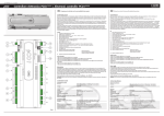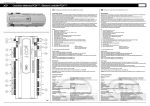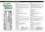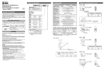
1
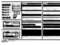
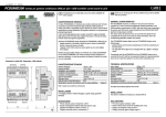
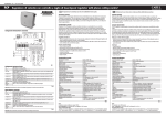
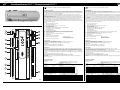
cod. +050003220 rel. 1.3 - 14.09.2004
pCO1
Controllore elettronico PCO1**** / Electronic controller PCO1****
Vi ringraziamo per la scelta fatta, sicuri che sarete soddisfatti del vostro acquisto.
1
J1
+5V Rif
G
GND
G0
J9
10
+V Term
2
Fuse
J10
11
Rx-/TxRx+/Tx+
B1
J2
B2
B3
B5
4
J3
GND
B6
Programming Key
+VDC
12
17
Clock card
B4
Analog Selection
3
15
J11
GND
13
GND
C1
6
NO1
NO2
VG
NO3
VG0
7
J4
Y1
Y3
Y4
ID1
ID2
ID3
8
J5
ID4
ID5
16
C1
C4
Serial Card
Y2
J12
NO4
NO5
J13
NO6
C4
C7
NO7
J14
ID8
IDC1
NO8
C8
J15
J6
GND
ID9
8
J7
ID10
ID11
C9
NO9
NO10
J16
NO11
C9
ID12
IDC9
ID13H
9
J8
ID13
IDC13
General features
pCO1 è un controllore elettronico a microprocessore, sviluppato da CAREL per molteplici applicaz. nel settore del condizionamento dell'aria e della
refrigerazione. Assicura la più assoluta versatilità di applicazione, consentendo di realizzare prodotti specifici su richiesta del cliente. pCO1 è
dedicato all'esecuzione del programma di regolazione ed è dotato del set di morsetti necessari alla connessione verso i dispositivi controllati
(ad esempio: valvole, compressori, contattori di potenza, ventilatori).
Il programma e i parametri sono memorizzati su FLASH-MEMORY, consentendo il loro mantenimento anche in caso di mancanza di
alimentazione (senza la necessità di una batteria di mantenimento). Il caricamento del programma può essere eseguito a mezzo PC o tramite
apposita chiave di programmazione. pCO1 permette anche la connessione alla rete locale pLAN (pCO Local Area Network) già prevista per i
modelli precedenti di controllori pCO e pCO2.
La rete pLAN è costituita da più controllori e più terminali, che interagiscono tra loro. Ogni controllore in rete pLAN può scambiare informazioni
(qualsiasi variabile, digitale o analogica, a seconda del programma applicativo utilizzato) con velocità di trasmissione elevata. Possono essere
collegate fino a 32 unità, tra pCO1 e terminali, in modo da condividere le informazioni in tempi molto brevi. Il collegamento verso la linea seriale di
supervisione/teleassistenza secondo lo standard RS485, viene realizzato tramite l'inserimento sul pCO1 di schede seriali opzionali con il protocollo
di comunicazione CAREL o MODBUS™.
pCO1 is an electronic controller based on a microprocessor designed by CAREL for a wide range of applications in the Air-Conditioning and
Refrigeration sectors. pCO1 is a flexible controller, which can respond to all customer requirements.
pCO1 carries out the regulation program and it is fitted with a set of terminals that connect it to the controlled devices (for ex. valves,
compressors, power contactors, fans).
The program and the parameters are stored on FLASH-MEMORY, thus allowing their permanence even in case of power failure (it is not
necessary for you to have a maintenance battery). The program can be loaded through PC or by means of a suitable programming key.
pCO1 allows the connection to the local pLAN network (pCO Local Area Network) - already provided in the previous versions of the pCO and
pCO2 controllers.
The pLAN network is made up of several controllers and terminals which interact among themselves. Every controller in the pLAN network can
exchange information (any digital and analog variable according to the used application program) at high transmission speed. In order to
rapidly exchange information, up to 32 units - pCO1 and terminals - can be connected to the pLAN network. The connection towards the
supervising/telemaintenance serial line, according to the RS485 standard, is carried out by inserting the optional serial cards on the pCO1 with
the CAREL standard communication protocol or MODBUS™.
Legenda
1. connettore per l’alimentazione [G (+), G0 (-)]
2. fusibile 250 Vac, 2 A ritardato (T2 A)
3. ingressi analogici universali NTC, 0…1 V, 0…5 V, 0…20 mA, 4…20 mA
4. ingressi analogici passivi NTC e ON/OFF
5. ingressi analogici passivi NTC
6. LED giallo indicazione presenza tensione di alimentazione e 3 LED di segnalazione
7. uscite analogiche 0…10 V e uscite PWM taglio di fase
8. ingressi digitali a 24 Vac/Vdc
9. ingressi digitali 230 Vac o 24 Vac/Vdc
10. connettore con Vrif per alimentazione sonde 5 V raziometrici e V Term per alimentazione terminale
11. connettore per tutti i terminali standard della serie pCO* e per il download del programma applicativo
12. connettore rete locale pLAN
13. connettore per la connessione alla chiave per la programmazione
14. uscite digitali a relè
15. sportello per selezione tipo di ingressi analogici
16. sportello per l’inserimento della scheda seriale:
- RS485 per supervisore
- RS232 per l’interfacciamento modem
- Gateway (convertitore di protocollo)
17. sportello per l’inserimento della scheda orologio
Key
1.
2.
3.
4.
5.
6.
7.
8.
9.
10.
11.
12.
13.
14.
15.
16.
Versioni disponibili:
• SMALL (cod. PCO1000AS0), MEDIUM (cod. PCO1000AM0)
• SMALL (cod. PCO1002AS0), MEDIUM (cod. PCO1004AM0) con uscite digitali a relè a stato solido (SSR)
• SMALL (cod. PCO1000CS0), MEDIUM (cod. PCO1000CM0) versione con memoria espansa
Kit connettori:
• SMALL (cod. PCO1CON0S0), MEDIUM (cod. PCO1CON0M0) a vite
• SMALL (cod. PCO1CON1S0, MEDIUM (cod. PCO1CON1M0) a molla
Available models:
• SMALL (cod. PCO1000AS0), MEDIUM (cod. PCO1000AM0)
• SMALL (cod. PCO1002AS0), MEDIUM (cod. PCO1004AM0), with solid status relay digital outputs (SSR)
• SMALL (cod. PCO1000CS0), MEDIUM (cod. PCO1000CM0) expanded memory version
Connectors kit:
• SMALL (cod. PCO1CON0S0), MEDIUM (cod. PCO1CON0M0) screw
• SMALL (cod. PCO1CON1S0, MEDIUM (cod. PCO1CON1M0) spring
Alimentazione
Power supply
Nell’installazione si deve utilizzare un trasformatore di sicurezza in Classe II di almeno 40 VA, per l’alimentazione di un solo controllore pCO1.
Si raccomanda di separare l’alimentazione del controllo pCO1 e terminale (o più pCO1 e terminali) dalla alimentazione del resto dei dispositivi
elettrici (contattori ed altri componenti elettromeccanici) all’interno del quadro elettrico. Qualora il secondario del trasformatore sia posto a
terra, verificare che il conduttore di terra sia collegato al morsetto G0. Attenersi a ciò per tutti i dispositivi connessi al pCO1. Se si alimentano
più schede pCO1 collegate in rete pLAN, assicurarsi che siano rispettati i riferimenti G e G0 (il riferimento G0 deve essere mantenuto per tutte
le schede).
In caso di utilizzo della rete pLAN, richiedere il manuale pCO1 CAREL.
During installation a safety Class II transformer rated at least 40 VA must be used to supply only one pCO1 controller.
It is advisable to keep separate the pCO1 controller and terminal (or more pCO1 and terminals) from the power supply of the other electric devices
(contactors and other electromechanical components) in the electric panel.
If the transformer secondary winding is grounded, check that the ground cable is connected to G0 terminal.
If more than one pCO1 board, connected to the pLAN, must be powered, please check if G and G0 references are observed (G0 reference
must be kept in every board).
If using the pLAN network, ask for the CAREL pCO1 user’s manual.
power supply connector [G (+), G0 (-)]
250 Vac, 2 A delayed fuse (T2 A)
universal analog inputs NTC, 0 to 1V, 0 to 5V, 0 to 20mA, 4 to 20mA
passive analog inputs NTC and ON/OFF
passive analog inputs NTC
yellow LED showing power supply voltage and 3 signalling LEDs
analog outputs 0 to 10V and PWM phase-cutting outputs
24 Vac/Vdc digital inputs
230 Vac or 24 Vac/Vdc digital inputs
connector with Vrif for the power supply of the 5 V ratiometric probes and V Term for the terminal power supply
connector for all pCO* series standard terminals and for the application program download
pLAN local network connector
connector for the connection to the programming key
relay digital outputs
hatch for selecting the type of the analogical inputs
hatch for inserting the serial card:
- RS485 for the supervisor
- RS232 for the modem interface
- Gateway (protocol converter)
17. hatch for inserting the clock card
Ulteriori specificazioni e notizie si possono reperire sul manuale di installazione - cod. +030221840.
Further information can be found in the installation manual - code +030221840.
AVVERTENZA: il pCO1 (come il pCO2) non può alimentare i terminali grafici PCOT00PGH0 e PCOI00PGL0, che devono quindi essere
alimentati con altre sorgenti.
WARNING: pCO1 (as pCO2)can not supply the graphic terminals PCOT00PGH0 and PCOI00PGL0, which can be supplied by other sources.
Caratteristiche tecniche
Technical Specifications
montaggio
GND
B8
Caratteristiche generali
Caratteristiche meccaniche
dimensioni
NC8
B7
5
Thank you for your choice. We trust you will be satisfied with your purchase.
C7
ID6
ID7
GB
NO12
C12
J17
NC12
14
NO13
ID14
C13
ID14H
NC13
J18
Fig. 1
versione SMALL inseribile su 13 moduli DIN, 110 x 227.5 x 60 mm
versione MEDIUM inseribile su 18 moduli DIN, 110 x 315 x 60 mm
su guida DIN
Mechanical Specifications
dimensions
SMALL board models can be mounted on 13 DIN modules, 110x227.5x60mm
MEDIUM board models can be mounted on 18 DIN modules, 110x315x60mm
on DIN rail
mounting
Contenitore plastico
materiale
tecnopolimero
autoestinguenza
V0 (secondo UL94) e 960 °C (secondo IEC 695)
prova biglia
125 °C
resistenza alle correnti striscianti
250 V
colore
grigio RAL7035
agganciabile su guida DIN secondo norme DIN 43880 e CEI EN 50022
feritoie di raffreddamento
Plastic case
material
technopolymer
self-extinguishing
V0 (complying with UL94) and 960 °C (complying with IEC 695)
ball pressure test
125 °C
comparative tracking index
250 V
colour
RAL7035 grey
it can be fastened on DIN rail according to DIN 43880 and CEI EN 50022 standards
cooling vent-holes
Caratteristiche elettriche
alimentazione (controllore con term. connesso)
morsettiera
Electrical specifications
power (controller with terminal connected)
terminal block
CPU
memoria programma (su FLASH MEMORY)
memoria dati (RAM statica)
memoria dati parametri
durata ciclo utile (applicazioni media complessità)
22…38 Vdc e 24 Vac ±15% 50/60 Hz - assorbimento massimo P= 13 W
con connettori maschio/femmina estraibili, tensione max 250 Vac
sezione cavo: min. 0,5 mm2 - max 2,5 mm2
H8S2320 a 16 bit e 14 MHz
1 MB organizzata a 16 bit (2 MB nella versione con memoria espansa)
128 kB organizzata a 8 bit (512 kB nella versione con memoria espansa)
4 kB organizzata a 16 bit (limite max: 400.000 scritture per locazione di memoria)
0,5 s (tipico)
GB
CPU
program memory (on FLASH MEMORY)
data memory (static RAM)
parameter data memory
operating cycle duration (middle complexity applications)
22 to 38 Vdc and 24 Vac ±15 % 50/60 Hz - P= 13 W maximum absorption
with removable-screw male/female connectors - max. voltage: 250 Vac
cable cross-section: min. 0.5 mm2 – max. 2.5 mm2
H8S2320, 16 bit and 14 MHz
1 MB organized in 16 bit (2 MB in expandend memory version)
128 kB organized in 16 bit (512 kB in expandend memory version)
4 kB organized in 16 bit (max limit: 400.000 writings per memory location)
0.5 s (typical value)
Dip-switch per selezionare il tipo di sonda / Dip-switch for selecting the probe type
B1
B2
B3
B4
Ingressi analogici
conversione analogica
tipo
B5 B6
ON
OFF
1 2 3 4 5 6
1 2 3 4 5 6
1 2 3 4 5 6
1 2
0 1V
AVVERTENZA: per l’alimentazione di eventuali sonde attive, è possibile utilizzare i 24 Vdc disponibili sul morsetto +Vdc, la corrente massima
erogabile è di 100 mA protetta contro i corti circuiti. A differenza del pCOB il segnale 0…1 Vdc è da intendersi limitato al range ristretto 0…1 V
e non è quindi sempre compatibile con il segnale standard 10 mV/°C delle sonde CAREL (per temperature negative e superiori a 100 °C può
generare allarme sonda), per i segnali in temperatura usare quindi 4…20 mA o NTC).
WARNING: for powering any active probe, it is possible to use the 24 Vdc placed on +Vdc terminal; the max. current that can be delivered is
100 mA thermally protected against short circuits. Unlike pCOB the signal 0 to 1Vdc is limited to the restricted range 0 to 1 V, so it is not always
compatible with the standard signal 10 mV/°C of CAREL probes (if the temperature is below zero or higher than 100 °C, it can cause probe
alarm). So, for the temperature signals use 4 to 20 mA or NTC).
Ingressi digitali
tipo
optoisolati
numero massimo
8, 14, rispettivamente sulle schede: SMALL e MEDIUM, secondo le combinazioni riportate qui sotto:
N. ing. optois. a 24 Vac 50/60 Hz o 24 Vdc
N. ing. optois. a 24 Vac/Vdc o 230 Vac (50/60 Hz)
SMALL
8
nessuno
MEDIUM
8+4
2
Digital inputs
type
max. number
1 2 3 4 5 6
1 2 3 4 5 6
AVVERTENZE:
Input B1, B2, B3, B4
0 20mA
1 2 3 4 5 6
1 2 3 4 5 6
0 5V
Input
OFF
ON
OFF
OFF
OFF
OFF
0 1V
OFF
ON
OFF
OFF
OFF
ON
NTC
0 20mA
0 5V
1 2 3 4 5 6
Input
ON
OFF
Esempio/Example
B1
B2
B3
B4
digital input
NTC
ON
OFF
ON
OFF
0 1V
NTC
0 20mA
0 5V
Uscite digitali
numero massimo
B5 B6
NTC digital input
digital
input
Fig. 2
NTC
pCO1 versione MEDIUM 18 moduli DIN/ pCO1 MEDIUM model 18 DIN modules
2 uscite (Y1 e Y2) 0…10Vdc optois. e 2 uscite (Y3 e Y4) PWM taglio di fase con impulso a 5V di durata programmab.
esterna 24 Vac/Vdc
8 bit
1 kΩ (10 mA) per 0…10 V e 470 Ω (10 mA) per PWM
8, 13, rispettivamente sulle schede: SMALL, MEDIUM; tipo a relè
Sono raggruppate a 3 con due morsetti di polo comune per un facile assemblaggio dei poli comuni. Prestare attenzione alla corrente
circolante nei morsetti comuni in quanto la stessa non deve superare la corrente nominale di un singolo morsetto, ovvero: 8 A per i morsetti
estraibili. I relè sono divisi in gruppi, a seconda della distanza di isolamento. All’interno di un gruppo, i relè hanno tra loro isolamento
principale e quindi devono essere sottoposti alla medesima tensione (generalmente 24 Vac o 230 Vac). Tra i gruppi c’è il doppio isolamento
quindi i gruppi possono essere a tensione diversa.
In ogni caso tra ogni morsetto delle uscite digitali e il resto del controllo esiste il doppio isolamento.
gruppi:
contatti in scambio:
potenza commutabile:
uscite a SSR:
1, 2, 3, 4, 5, 6 - 7 - 8 (relè di allarme) - 9, 10, 11, 12, 13
1,3 rispettivamente sulle versioni SMALL, MEDIUM
2000 VA, 250 Vac, 8 A resistivi, 2 A FLA, 12 A LRA secondo UL873, (30.000 cicli)
2 A resistivi, 2 A induttivi, cosϕ=0,4, 2(2) A secondo EN 60730-1, (100.000 cicli)
2 in alternativa ai relè n˚ 7 e 8 (SMALL), 4 in alternativa ai relè n˚ 7, 8, 12 e 13 (MEDIUM);
24 Vac/Vdc, Pmax= 10 W
Collegamento al terminale utente
tipo
connettore per terminale
connettore per pLAN*
driver
315
Fig. 3
pCO1 versione SMALL 13 moduli DIN/ pCO1 SMALL model
110
227.5
tot. ing.
8
14
- 230 Vac 50/60 Hz (10/-15 %)
- i due ingressi a 230/24 Vac, hanno il medesimo polo comune e quindi saranno entrambi a 24Vac/Vdc o 230 Vac.
L’isolamento è principale.
- separare quanto più possibile i cavi dei segnali delle sonde e degli ingressi digitali dai cavi relativi ai carichi induttivi e di
potenza, per evitare possibili disturbi elettromagnetici.
Uscite analogiche
tipo e N. max.
alimentazione
risoluzione
carico massimo
Input B5, B6
1 2 3 4 5 6
max. number
time constant for each input
0 to 20 mA inputs internal resistance
10 bit A/D converter, built-in CPU
passive: CAREL NTC temp. probe sensor, (-50T90 °C; R/T 10 kΩ at 25 °C), (input B5, B6, B7,B8)
or free contact digital input (5 mA), that can be selected via dip-switch (B5, B6)
universal: CAREL NTC temp. probe (see passive type), voltage: 0 to 1 Vdc or 0 to 5 Vdc,
current: 0 to 20 mA or 4 to 20 mA, that can be selected via dip-switch (B1, B2, B3, B4 inputs)
6, 8, on SMALL, MEDIUM, boards respectively
1s
100Ω
numero massimo
costante di tempo ingressi
resistenza interna ingressi 0…20 mA
NTC
1 2 3 4 5 6
Analog inputs
analog conversion
type
A/D converter a 10 bit CPU built-in
passivo: sensore di temp. NTC CAREL, (-50T90 °C; R/T 10 kΩ a 25 °C) (ingressi B5, B6,
B7, B8) o input digitale da contatto pulito (5 mA), selezionabili via dip-switch (B5, B6)
universale: sensore di temp. NTC CAREL (vedi tipo passivo), tensione: 0…1 Vdc o 0…5 Vdc,
corrente: 0…20 mA o 4…20 mA, selezionabili via dip-switch (ingressi B1, B2, B3, B4)
6, 8, rispettivamente sulle schede SMALL, MEDIUM
1s
100 Ω
SMALL
MEDIUM
optoinsulated
8, 14 on SMALL and MEDIUM boards respectively according to the combinations shown below:
No. of optoins. inputs at 24 Vac
No. of optoins. inputs at 24 Vac/Vdc
50 to 60 Hz or 24 Vdc
or 230 Vac (50/60 Hz)
8
none
8+4
2
total inputs
8
14
WARNING: - 230 Vac 50/60 Hz (10/-15 %)
- the two 230/24Vac inputs have the same common pole, so they both will be at 24 Vac or 230 Vac. The insulation is principal.
- please keep probe and digital input leads as far as possible from power cables to avoid possible electromagnetic noise.
Analog outputs
type and max. number
power supply
resolution
max. load
2 outputs (Y1 and Y2) optoinsulated 0 to 10 Vdc and 2 outputs (Y3 and Y4) PWM phase-cutting with impulse at
5 V programmable duration
24 Vac/Vdc external
8 bit
1kΩ (10 mA) for 0 to 10V and 470Ω (10 mA) for PWM
Digital outputs
max. number
8, 13, on SMALL, MEDIUM boards respectively, type relay
They are grouped in 3 with two common pole termin. in order to assemble the common poles easily. Be careful to the current flowing in common
termin., because it must not exceed the rated current of each single termin., that is: 8 A for removable-screw terminals.The relays are divided into
groups, according to the insulat. distance. Inside each group the relays have their single own main insulat., so they must be exposed to the same voltage
(in general 24 Vac or 230 Vac). Among the groups there is double-insulat., therefore the groups can be of different voltage.
Anyway the double-insulat. does exist towards the rest of the control. and its presence is guaranteed among digital output termin.
groups:
changeover contacts:
commutable power:
outputs at SSR:
1, 2, 3, 4, 5, 6 - 7 - 8 (alarm relay) - 9, 10, 11, 12, 13.
1,3 respectively on the SMALL, MEDIUM versions
2000 VA, 250 Vac, 8 A resistive, 2 A FLA, 12 A LRA according to UL873, (30,000 cycles)
2 A resistive, 2 A inductive, cosϕ= 0,4, 2(2) A according to EN 60730-1, (100,000 cycles)
2 instead of the rel. no˚ 7 and 8 (SMALL), 4 instead of the rel. no˚ 7, 8, 12 and 13 (MEDIUM);
24 Vac/Vdc, Pmax=10W
Connection to the user terminal
type
asynchronous 2-lead half duplex dedicated
connector for terminal
6-way telephone cable
connector for pLAN
3-way plug-in connector
driver
CMR 7V balanced differential (type RS485)
asincrono half duplex a 2 fili dedicato
tipo telefonico 6 vie
connettore estraibile 3 vie
differenziale bilanciato CMR 7 V (tipo RS485)
Le distanze massime ammesse tra terminale e pCO1 sono quelle riportate nella seguenta tabella:
con cavo telefonico
con cavo schermato AWG24
resistenza del cavo (Ω/m)
distanza massima (m)
resistenza del cavo (Ω/m)
distanza massima (m)
0,14
600
≤0,078
600
0,25
400
The maximum distances between the terminal and pCO1 are described in the following table:
with telephone-type cable
with AWG24 shielded cable
cable resistance (Ω/m)
max. distance (m)
cable resistance (Ω/m)
max. distance (m)
≤ 0.14
600
≤0.078
600
≤ 0.25
400
* Nota: a differenza del pCOB e pCO2 l’indirizzamento pLAN non avviene tramite dip switch ma tramite sequenze di operazioni sul
terminale. A tal proposito consultare il manuale software.
* Note: unlike pCOB and pCO2 the pLAN addressing doesn't take place through dip switch but through operation sequences on the display. With
regards to this, please refer to the software manual.
Altre caratteristiche
condizioni di immagazzinamento
condizioni di funzionamento
grado di protezione
inquinamento ambientale
classe secondo la protezione contro le scosse elettriche
PTI dei materiali per isolamento
periodo delle sollecitazioni elettriche delle parti isolanti
tipo azioni
tipo disconnessione o microinterruzione
categoria di resistenza al calore e al fuoco
immunità contro le sovratensioni
caratteristiche di invecchiamento (ore di funzionamento)
n. cicli di manovra operazioni automatiche
classe e struttura del software
Il dispositivo non è destinato ad essere tenuto in mano.
Other specifications
storage conditions
operating conditions
index of protection
environmental pollution
classification according to protection against electric shock
PTI of insulating materials
period of electric stress across insulating parts
type of actions
type of disconnection or microinterruption
category of resistance to heat and fire
immunity against voltage surges
ageing period (operating hours)
no. of automatic operating cycles
software Class and structure
The device is not intended to be hand-held.
-20T70, 90 % UR non condensante
-10T60, 90 % UR non condensante
IP20, IP40 nel solo frontalino
normale
da integrare su apparecchiature di Classe I e/o II
250 V
lungo
1C
microinterruzione
categoria D (UL94 - V0)
categoria 1
80.000
100.000 (EN 60730-1); 30.000 (UL 873)
Classe A
-20T70, 90 %r.H. non-condensing
-10T60, 90 %r.H. non-condensing
IP20, IP40 (front panel only)
normal
should be integrated into Class I and/or II devices
250 V
long
1C
microinterruption
D (UL94 - V0) category
category 1
80,000
100,000 (EN 60730-1) 30,000 (UL873)
Class A
GB
Avvertenza: per applicazioni soggette a forte vibrazioni (1,5 mm pk-pk 10/55 Hz) si consiglia di fissare tramite fascette i cavi collegati al pCO1
a circa 3 cm di distanza dai connettori.
Warning: for applications subject to strong vibrations (1.5 mm pk-pk 10/55 Hz), we suggest you to fasten, through fastening clamps, the
cables connected to the pCO1 at about 3 cm of distance from the connectrors.
Il programma applicativo potrà essere scaricato nella memoria flash attraverso la key “PCO100KEY0” o un PC mediante il programma
“WINLOAD32” da richiedere alla CAREL.
The application program can be downloaded from the flash memory through the key “PCO100KEY0” or a PC using the program “
WINLOAD32” to be required to CAREL.
60
Fig. 4
CAREL S.p.A.
Via dell’Industria, 11 - 35020 Brugine - Padova (Italy)
Tel. (+39) 0499716611 – Fax (+39) 0499716600
http://www.carel.com – e-mail: [email protected]
CAREL si riserva la possibilità di apportare modifiche o cambiamenti ai propri prodotti senza alcun preavviso. / CAREL reserves the right to alter the features of its products without prior notice.
cod. +050003220 rel. 1.3 - 14.09.2004