1
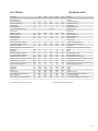
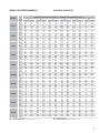
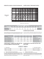
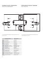
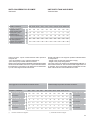
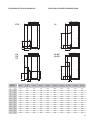
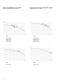
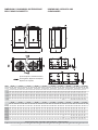
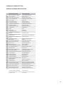
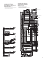
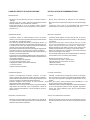
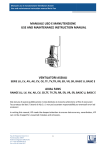
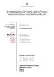
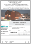
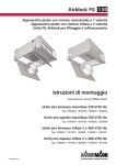
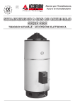
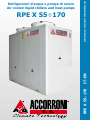
Informazioni tecniche/Technical Manual
IT-EN
RPE X 55÷170
RPE X 55÷170
Refrigeratori d’acqua e pompe di calore
Air cooled liquid chillers and heat pumps
2
INDICE
•
•
•
•
•
•
•
•
•
•
•
•
•
•
•
•
•
•
•
•
•
Descrizione generale
Caratteristiche costruttive
Accessori montati in fabbrica
Accessori forniti separatamente
Condizioni di riferimento
Limiti di funzionamento
Dati tecnici
Rese in raffreddamento
Perdite di carico circuito idraulico
Limiti portata acqua evaporatori
Fattori di correzione
Coefficienti correttivi per fattori
di sporcamento evaporatore
Schema circuito frigorifero:
Unità per solo raffreddamento
Circuito idraulico:
Caratteristiche generali
Schema circuito idraulico
Unità con serbatoio e pompe
Dati tecnici
Posizione attacchi idraulici
Curve caratteristiche delle pompe
Dimensioni d'ingombro distribuzione pesi
e spazi di rispetto
Pressione sonora
Sistema di regolazione con microprocessore
Legenda schemi circuiti elettrici
Schemi circuiti elettrici
Consigli pratici d'installazione
Pag.
4
4
5
5
5
5
6, 7
8
9
9
9
9
10
11
11
12
13
14
15
16
17
18
19 - 21
22
INDEX
•
•
•
•
•
•
•
•
•
•
•
•
•
•
•
•
•
•
•
•
•
General description
Technical features
Factory fitted accessories
Loose accessories
Reference conditions
Operating range
Technical data
Cooling capacity
Water circuit pressure drops
Evaporator water flow limits
Correction factors
Evaporator fouling factors
corrections
Refrigeration circuit diagram:
Only cooling units
Water circuit:
General characteristics
Water circuit diagram
Units with storage tank and pump
Technical data
Position of water connections
Characteristic pump curves
Dimensions, clearances
and Weights
Sound pressure level
Microprocessor control system
Wiring diagrams explanation
Wiring diagrams
Installation recommendations
Pag.
4
4
5
5
5
5
6, 7
8
9
9
9
9
10
11
11
12
13
14
15
16
17
18
19 - 21
22
3
DESCRIZIONE GENERALE
Refrigeratori d’acqua condensati ad aria con ventilatori assiali per
installazione esterna. La gamma comprende 10 modelli che coprono
potenzialità frigorifere da 47 a 178 kW.
GENERAL DESCRIPTION
Air cooled water chiller units, with axial fans for outdoor installation. The range consists of 10 models covering a cooling
capacity from 47 to 178 kW.
CARATTERISTICHE COSTRUTTIVE:
Struttura. Di tipo autoportante, realizzata in lamiera zincata con
un’ulteriore protezione ottenuta tramite verniciatura a polveri poliestere. I pannelli, facilmente rimovibili, permettono l’accesso all’interno
dell’unità per le operazioni di manutenzione e riparazione.
Compressori. Scroll, ermetici, con spia livello olio. Sono dotati di
protezione termica incorporata e di resistenza carter, e sono montati
su supporti antivibranti in gomma.
Ventilatori. Di tipo assiale direttamente accoppiati a motori trifase
a rotore esterno. Una rete di protezione antinfortunistica è posta
sull’uscita dell’aria. Per le unità super silenziate si utilizzano ventilatori
a basso numero di giri e di conseguenza, per alcuni modelli, aumenta
il numero dei ventilatori.
Condensatore. Costituito da una batteria alettata con tubi in rame ed
alette in alluminio. Le circuitazioni sul lato refrigerante sono realizzate
in modo da ottenere un circuito nei modelli X 55÷X 135 e due circuiti
indipendenti nei modelli X 155÷ X 170.
Evaporatore. Del tipo a piastre saldobrasate in acciaio inox AISI 316,
con un circuito sul lato refrigerante ed uno sul lato acqua nei modelli
X 55÷X 135; con due circuiti indipendenti sul lato refrigerante ed
uno sul lato acqua nei modelli X 155÷ X 170.
Nelle unità a pompe di calore è di serie la resistenza antigelo.
Quadro elettrico. Include: interruttore generale con bloccoporta;
fusibili; relè termici a protezione dei compressori e termocontatti
per i ventilatori; relè di interfaccia; morsetti per collegamenti esterni.
Microprocessore per la gestione automatica dell’unità. Permette di
visualizzare in qualsiasi istante lo stato di funzionamento dell’unità,
di controllare la temperatura dell’acqua impostata e quella effettiva
e, in caso di blocco parziale o totale dell’unità, di evidenziare quali
sicurezze sono intervenute.
TECHNICAL FEATURES:
Frame. Self-supporting galvanized steel frame further protected
with polyester powder painting. Easy to remove panels allow
access to the inside of the unit for maintenance and other necessary operations.
Compressors. Scroll with oil sight glass. They are furnished with
an internal overheat protection and crankcase heater, installed
on rubber shock absorbers.
Fans. Axial fans directly coupled to a three-phase electric motor
with external rotor. A safety fan guard is fitted on the air flow
discharge. On the super silenced units there are fans with a low
rpm therefore some models have more fans.
Condenser. Made up of a finned battery with copper pipes and
aluminium fins. Circuits on the refrigerant side are made to create
one circuit in models X 55÷X 135 and two independent circuits
in models X 155÷ X 170.
Evaporator . AISI 316 stainless steel braze welded plate type:
with one circuit on the refrigerant side and one on the water side
in models X 55÷X 135; with two independent circuits on the refrigerant side and one on the water side in models X 155÷ X 170.
Electrical board. Includes: main switch with door safety interlock;
fuses, overload protection for compressors and thermocontacts for
fans; interface relays; electrical terminals for external connections.
Microprocessor for automatic control of the unit allowing continuous display of the operational status of the unit, control set
and real water temperature and, in case of partial or total block
of the unit, indication of security device that intervened.
Circuito frigorifero.
Realizzato in tubo di rame, comprende per tutti i modelli i seguenti
componenti: valvola di espansione termostatica con equalizzazione
esterna; filtro disidratatore; indicatore di liquido ed umidità; pressostati
di alta e bassa pressione (a taratura fissa).
Circuito idraulico include: evaporatore, sonda di lavoro, sonda
antigelo, pressostato differenziale acqua e valvole di sfiato aria manuale.
Refrigerator circuits
Made of copper pipe, it includes the following components on all
models: Thermostat expansion valve with external equalisation;
dehydrator filter; liquid and humidity indicator; high and low pressure gauges (fixed calibration).
The hydraulic circuit includes: Evaporator, work probe, antifreeze
probe, differential water pressure gauge and manual air breather
valve.
4
Circuito idraulico include: evaporatore, sonda di lavoro, sonda antigelo,
pressostato differenziale acqua, valvole di sfiato aria manuale, pompa
di circolazione INVERTER, vaso d'espansione, valvola di
sicurezza, manometro e rubinetti di carico e scarico impianto.
ACCESSORI MONTATI IN FABBRICA:
IM - Interruttori magnetotermici in alternativa a fusibili e relè termici.
SL - Silenziamento unità. I compressori vengono dotati di copertura
fonoisolante.
CT - Controllo condensazione fino a temperature dell’aria esterna di
0 °C ottenuto tramite arresto di alcuni ventilatori.
CC - Controllo condensazione ottenuto tramite la regolazione in
continuo della velocità di rotazione dei ventilatori fino a temperature dell’aria esterna di –20° C in funzionamento come
refrigeratore .
BT - Kit bassa temp.ra, necessario nei casi di funzionamento dell'unità in condizioni di uscita dell'acqua all'evaporatore inferiore ai 5°C.
DS - Desurriscaldatore con recupero del 20%.
RT - Recuperatore calore totale con recupero del 100%.
SI - Serbatoio inerziale 400 l: modelli X 55÷X 135.
- Serbatoio inerziale 600 l: modelli X 155÷X 170.
PS - Pompa circolazione inserita all’interno dell’unità.
PD - Doppia pompa di circolazione. Inserite all'interno
dell'unità, lavorano una in stand-by all'altra e ad ogni richiesta di
accensione viene attivata per prima la pompa con meno ore di
funzionamento.
ACCESSORI FORNITI SEPARATAMENTE:
MN - Manometri alta/bassa pressione per ogni circuito frigorifero.
CR - Pannello comandi remoto da inserire in ambiente per il comando a distanza dell’unità, con funzioni identiche a quello inserito
in macchina.
IS - Interfaccia seriale RS 485 per collegamento a sistemi di controllo
e di supervisione centralizzati.
RP - Reti protezione batterie in acciaio con trattamento di cataforesi
e verniciatura.
AG - Antivibranti in gomma da inserire alla base dell’unità per
smorzare eventuali vibrazioni dovute al tipo di pavimento ove la
macchina è installata.
CONDIZIONI DI RIFERIMENTO
I dati tecnici, indicati a pagina 11 e 12, si riferiscono alle seguenti
condizioni di funzionamento:
- in raffreddamento:
• temperatura ingresso acqua fredda 12°C
• temperatura uscita acqua fredda 7°C
• temperatura ingresso aria condensatore 35°C.
- in riscaldamento:
• temperatura ingresso acqua 40°C
• temperatura uscita acqua 45°C
• aria all'ingresso batteria 7°C b.s., 6°C b.u.
- pressione sonora (DIN 45635):
rilevata in campo libero a 1 m di distanza e ad 1,5 m dal suolo.
Secondo normativa DIN 45635.
- pressione sonora (ISO 3744):
rilevata in campo libero a 1 m dall'unità. Valore medio come definito
dalla ISO 3744.
L'alimentazione elettrica di potenza é 400V/3Ph/50Hz; l'alimentazione
elettrica ausiliaria é 230V/1Ph/50Hz.
LIMITI DI FUNZIONAMENTO
Temperatura acqua in ingresso
°C
Temperatura acqua in uscita
°C
Salto termico acqua (1)
°C
Temperatura aria esterna
Minima temperatura dell’acqua
refrigerata con l’impiego di glicole
Max. pressione di esercizio lato
acqua scambiatore
°C
°C
FACTORY FITTED ACCESSORIES:
IM - Magnetothermic switches instead of fuses and thermal relais.
SL - Unit silencement. The compressors are equipped with
sound-absorbing covering.
CT - Condensation control to outside air temperatures of 0°C
obtained by means of stopping some fans.
CC - Condensation control obtained by means of continuous adjustment of the fan rotation speed up to outside air temperatures of - 20° C
in operation as a refrigerator.
BT - Low temperature kit, required in case the unit will work with
evaporator’s outlet water temperature below 5°C.
DS - Desuperheater with 20% heat recovery.
RT - Total heat regeneration with 100% recovery.
SI - Inertial tank 400 l: models X 55÷X 135.
- Inertial tank 600 l : models X 155÷X 170.
PS - Circulating pump inserted inside the unit.
PD - Double circulating pump. Installed in the unit, working
one in stand-by to the other; by every start request, the pump
with the least number of working hours is activated first.
LOOSE ACCESSORIES:
MN - High and low pressure gauges for every refrigeration circuit.
CR - Remote control panel to be inserted in the room for remote
control of the unit, with the same functions as that inserted in the
machine.
IS - RS 485 serial interface for connection to controls and centralized supervision systems.
RP - Coil protection guards in steel with cataphoresis treatment
and painting.
AG - Rubber vibration dampers to be inserted at the bottom of the
unit to dampen possible vibrations due to the type of floor where
the machine is installed
REFERENCE CONDITIONS
All technical data, indicated on pages 11 and 12, refer to the following
unit operating conditions:
- cooling:
• entering water temperature 12°C
• leaving water temperature 7°C
• ambient air on condenser 35°C.
- heating:
• entering water temperature 40°C
• leaving water temperature 45°C
• ambient inlet air 7°C d.b., 6°C w.b.
- sound pressure level (DIN 45635):
measured in free field conditions at 1 m from the unit and at 1,5
m from the ground. According to DIN 45635.
- sound pressure level (ISO 3744):
measured in free field conditions at 1 m. As defined by ISO 3744.
The power supply is 400V/3Ph/50Hz; auxiliary supply is
230V/1Ph/50Hz.
Raffreddamento
Cooling
min
8
5
3
10 *
Riscaldamento
Heating
max
min
max
20
15
9
46**
25
30
3
-10
45
50
10
20
-8
kPa
* Per le versioni standard può essere portata a -20 °C con accessorio
controllo di condensazione.
** Salvo dove diversamente limitato.
(1) In ogni caso la portata d'acqua dovrà rientrare nei limiti riportati a pag. 9.
5
The hydraulic circuit includes: Evaporator, work probe, antifreeze
probe, differential water pressure gauge, manual air breather valves,
INVERTER circulation pump, expansion chamber, safety valve, system
load and discharge pressure gauges and faucets.
----1000
OPERATING RANGE
Inlet water temperature
Outlet water temperature
Water thermal difference (1)
Ambient air temperature
Minimun chilled water outlet
temperature with glycol mixture
Max. operating pressure heat
exchanger water side
* This value can be reduced until -20°C with an optional accessory supplied
prefabricated..
** Exept where it is differently limitated .
(1) In all cases the water range will have to re-enter within the reported
limits on pag. 9.
DATI TECNICI
TECHNICAL DATA
X 55
MODELLO
X 62
X 72
X 80
X 90
MODEL
Raffreddamento:
Potenza frigorifera (1)
Potenza assorbita (1)
Compressori
Circuiti frigoriferi
Gradini di parzializzazione
kW
kW
n°
n°
%
46,6
53,7
62,2
71,3
81,7
16,6
19,4
22,4
25,7
29,0
2
2
2
2
2
1
1
1
1
1
< - - - - - - - - - 50 / 100 - - - - - - - - - >
Cooling:
Cooling Capacity (1)
Absorbed power (1)
Compressors
Refrigerant Circuits
Capacity steps
Evaporatore:
Portata acqua (1)
Perdite di carico (1)
Attacchi idraulici
Contenuto acqua
l/s
kPa
"G
dm³
2,27
45
1"½
2,6
2,62
48
1"½
3,1
3,03
43
1"½
3,6
3,48
48
1"½
4
3,98
43
1"½
4,6
Evaporator:
Water flow (1)
Pressure drops (1)
Water connections
Water volume
Compressore:
Potenza assorbita unitaria (1)
Corrente assorbita unitaria (1)
Carica olio unitaria
kW
A
kg
7,4
16
3,3
8,7
16,6
3,3
9,9
18,6
3,3
11,5
20,5
3,3
13,1
25,8
6,7
Compressor:
Unitary absorbed power (1)
Unitary absorbed current (1)
Oil charge
4,8
1
1,3
2,5
66,5
4,7
1
1,3
2,5
66,5
7,1
2
2,0
5,0
70,5
7,1
2
2,0
5,0
70,5
7,3
2
2,0
5,0
70,5
Standard version and with SL accessory:
Airflow
Fans
Nominal power - fans
Nominal current - fans
Sound pressure level - DIN (1)
Versione standard e con accessorio SL:
Portata aria
m³/s
Ventilatori
n°
Potenza nominale ventilatori
kW
Corrente nominale ventilatori
A
Pressione sonora - DIN (1)
dB(A)
Pressione sonora con accessorio SL - DIN (1) dB(A)
64,5
64,5
68,5
68,5
68,5
Sound pressure level with SL accessory - DIN (1)
Pressione sonora - ISO (1)
dB(A)
56,5
56,5
60,5
60,5
60,5
Sound pressure level - ISO (1)
Pressione sonora con accessorio SL - ISO (1) dB(A)
54,5
54,5
58,5
58,5
58,5
Sound pressure level with SL accessory - ISO (1)
kg
12
14
14
14
18
mm
mm
mm
kg
kg
kg
kg
2350
1100
1920
595
605
610
620
2350
1100
1920
624
634
639
649
2350
1100
1920
663
673
678
688
2350
1100
1920
682
692
697
707
2350
1100
2220
791
801
806
816
Carica refrigerante R410A
Lunghezza
Larghezza
Altezza
Peso di trasporto
Peso di trasporto con accessorio SL
Peso di trasporto ST
Peso di trasporto ST con accessorio SL
(1) Condizioni di riferimento a pagina 5.
Refrigerant charge R410A
Lenght
Width
Height
Transport weight
Transport weight with SL accesory
ST transport weight
ST transport weight with SL accesory
(1) Referential conditions at page 5.
6
DATI TECNICI
TECHNICAL DATA
MODELLO
Raffreddamento:
Potenza frigorifera (1)
Potenza assorbita (1)
kW
kW
Compressori
Circuiti frigoriferi
Gradini di parzializzazione
n°
n°
%
X 120
X 135
X 155
X 170
MODEL
94,3
32,5
108
38,9
124
44,4
144
51,4
174
59,8
Cooling:
Cooling Capacity (1)
Absorbed power (1)
3
3
3
1
1
1
<-- 33 / 66 / 100 -->
4
4
2
2
<--25/50/75/100-->
Compressors
Refrigerant Circuits
Capacity steps
Evaporatore:
Portata acqua (1)
Perdite di carico (1)
Attacchi idraulici
Contenuto acqua
l/s
kPa
"G
dm³
4,58
50
2"½
6,3
5,27
46
2"½
7,6
6,06
53
2"½
8,2
7,04
48
2"½
8,6
8,49
48
2"½
10
Evaporator:
Water flow (1)
Pressure drops (1)
Water connections
Water volume
Compressore:
Potenza assorbita unitaria (1)
Corrente assorbita unitaria (1)
Carica olio unitaria
kW
A
kg
9,8
18,7
3,3
11,3
18,9
3,3
13,1
25,9
6,7
11,5
21,1
3,3
13,1
25,2
6,7
Compressor:
Unitary absorbed power (1)
Unitary absorbed current (1)
Oil charge
Versione standard e con accessorio SL:
Portata aria
m³/s
Ventilatori
n°
Potenza nominale ventilatori
kW
Corrente nominale ventilatori
A
Pressione sonora - DIN (1)
dB(A)
7,1
2
2,0
5,0
70,5
9,7
2
4,0
8,0
71,5
9,7
2
4,0
8,0
71,5
11,4
2
4,0
8,0
71,5
15,0
3
5,6
12,0
71,5
Standard version and with SL accessory:
Airflow
Fans
Nominal power - fans
Nominal current - fans
Sound pressure level - DIN (1)
Pressione sonora con accessorio SL - DIN (1) dB(A)
68,5
69,5
69,5
69,5
69,5
Sound pressure level with SL accessory - DIN (1)
Pressione sonora - ISO (1)
dB(A)
60,5
61,5
61,5
61,5
61,5
Sound pressure level - ISO (1)
Pressione sonora con accessorio SL - ISO (1) dB(A)
58,5
59,5
59,5
59,5
59,5
Sound pressure level with SL accessory - ISO (1)
kg
24
24
26
28
32
mm
mm
mm
kg
kg
kg
kg
2350
1100
2220
878
893
898
918
2350
1100
2220
927
942
947
967
2350
1100
2220
1036
1051
1056
1076
3550
1100
2220
1135
1155
1155
1175
3550
1100
2220
1374
1394
1394
1414
Carica refrigerante R410A
Lunghezza
Larghezza
Altezza
Peso di trasporto
Peso di trasporto con accessorio SL
Peso di trasporto ST
Peso di trasporto ST con accessorio SL
(1) Condizioni di riferimento a pagina 5;
(2) Non disponibile;
7
X 105
(1)
(2)
Refrigerant charge R410A
Lenght
Width
Height
Transport weight
Transport weight with SL accesory
ST transport weight
ST transport weight with SL accesory
Referential conditions at page 5;
Not available;
RESE IN RAFFREDDAMENTO
MOD.
COOLING CAPACITY
TEMPERATURA ARIA ESTERNA °C / AMBIENT AIR TEMPERATURE °C
25
28
32
35
40
45
To (°C)
kWf
kWe
kWf
kWe
kWf
kWe
kWf
kWe
kWf
kWe
kWf
kWe
X 55
5
6
7
8
9
10
49,7
51,4
52,9
54,7
56,4
58,1
13,2
13,3
13,3
13,5
13,6
13,7
48,2
49,9
51,5
53,1
54,8
56,4
13,9
13,9
14,1
14,2
14,4
14,5
46,4
47,8
49,4
50,9
52,4
54,1
15,0
15,2
15,2
15,3
15,4
15,6
44,6
46,2
46,6
49,3
50,8
52,2
15,8
15,9
16,6
16,2
16,4
16,4
42,0
43,2
44,7
46,2
47,6
49,1
17,5
17,6
17,7
17,8
18,0
18,1
38,9
40,3
41,6
43,0
-----
19,2
19,3
19,5
19,5
-----
X 62
5
6
7
8
9
10
57,3
59,2
61,1
63,1
65,1
67,0
15,3
15,4
15,5
15,7
15,8
15,9
55,6
57,5
59,3
61,3
63,2
65,0
16,1
16,2
16,4
16,5
16,7
16,8
53,5
55,1
56,9
58,7
60,5
62,4
17,4
17,6
17,7
17,8
17,9
18,1
51,5
53,3
53,7
56,8
58,5
60,2
18,4
18,5
19,4
18,8
19,0
19,1
48,4
49,9
51,6
53,3
54,9
56,6
20,3
20,4
20,6
20,7
20,9
21,0
44,9
46,5
47,9
49,6
51,2
52,8
22,3
22,4
22,6
22,7
22,8
23,1
X 72
5
6
7
8
9
10
66,3
68,5
70,6
73,0
75,3
77,5
17,9
18,0
18,1
18,3
18,5
18,6
64,3
66,5
68,6
70,9
73,1
75,2
18,8
18,9
19,2
19,3
19,5
19,6
61,9
63,7
65,8
67,9
69,9
72,1
20,3
20,5
20,6
20,8
20,9
21,1
59,5
61,6
62,2
65,7
67,7
69,7
21,5
21,6
22,4
21,9
22,1
22,3
56,0
57,7
59,6
61,6
63,5
65,5
23,6
23,8
24,0
24,1
24,3
24,4
51,9
53,8
55,4
57,3
-----
25,9
26,1
26,3
26,4
-----
X 80
5
6
7
8
9
10
76,1
78,7
81,1
83,8
86,4
89,0
20,5
20,6
20,7
21,0
21,1
21,3
73,8
76,4
78,8
81,3
83,9
86,3
21,5
21,7
21,9
22,1
22,3
22,5
71,0
73,2
75,6
78,0
80,3
82,8
23,3
23,5
23,7
23,8
23,9
24,2
68,3
70,8
71,3
75,4
77,7
80,0
24,6
24,7
25,7
25,1
25,4
25,5
64,3
66,2
68,5
70,8
72,9
75,2
27,1
27,3
27,5
27,7
27,9
28,1
59,6
61,8
63,7
65,8
-----
29,8
29,9
30,2
30,3
-----
X 90
5
6
7
8
9
10
87,1
90,0
92,8
95,8
98,9
102
23,0
23,2
23,3
23,6
23,8
23,9
84,5
87,4
90,1
93,1
96,0
98,7
24,2
24,4
24,7
24,8
25,2
25,3
81,3
83,7
86,5
89,2
91,8
94,7
26,2
26,5
26,7
26,8
27,0
27,3
78,2
80,9
81,7
86,3
88,9
91,5
27,7
27,9
29,0
28,4
28,7
28,8
73,6
75,7
78,3
80,9
83,4
86,0
30,6
30,8
31,1
31,2
31,6
31,7
68,2
70,7
72,8
75,3
77,7
80,2
33,7
33,8
34,1
34,3
34,4
34,8
X 105
5
6
7
8
9
10
100
103
107
110
114
117
25,6
25,8
25,9
26,3
26,4
26,6
97,1
100
104
107
110
114
27,0
27,1
27,5
27,6
28,0
28,2
93,4
96,3
99,4
103
106
109
29,2
29,5
29,7
29,9
30,0
30,4
89,9
93,1
94,3
99,2
102
105
30,9
31,1
32,5
31,6
31,9
32,1
84,6
87,1
90,1
93,1
95,9
98,9
34,1
34,3
34,6
34,8
35,2
35,3
78,4
81,3
83,7
86,6
-----
37,6
37,7
38,1
38,2
-----
X 120
5
6
7
8
9
10
115
119
123
127
131
135
30,4
30,6
30,8
31,2
31,4
31,6
112
116
119
123
127
131
32,0
32,3
32,7
32,9
33,3
33,5
108
111
114
118
122
125
34,7
35,1
35,3
35,5
35,8
36,2
104
107
108
114
118
121
36,8
37,0
38,9
37,6
38,0
38,2
97,4
100
104
107
110
114
40,7
40,9
41,3
41,5
41,9
42,1
90,3
93,6
96,4
99,6
-----
44,8
45,0
45,4
45,6
-----
X 135
5
6
7
8
9
10
132
137
141
146
150
155
35,1
35,4
35,6
36,1
36,3
36,6
128
133
137
141
146
150
37,1
37,3
37,8
38,0
38,5
38,7
124
127
131
136
140
144
40,2
40,7
40,9
41,1
41,4
41,9
119
123
124
131
135
139
42,6
42,8
44,4
43,5
44,0
44,3
112
115
119
123
127
131
47,1
47,4
47,9
48,1
48,6
48,8
104
107
111
114
118
122
51,9
52,2
52,7
52,9
53,1
53,6
X 155
5
6
7
8
9
10
154
159
164
169
175
180
40,5
40,8
41,1
41,6
41,9
42,2
149
154
159
164
170
174
42,7
43,0
43,6
43,9
44,4
44,7
144
148
153
158
162
167
46,4
46,9
47,2
47,5
47,8
48,3
138
143
144
153
157
162
49,2
49,4
51,4
50,3
50,8
51,1
130
134
138
143
147
152
54,5
54,7
55,3
55,6
56,1
56,4
121
125
129
133
137
---
60,0
60,3
60,9
61,2
61,4
---
X 170
5
6
7
8
9
10
186
192
198
204
211
217
47,1
47,4
47,8
48,4
48,7
49,0
180
186
192
198
205
210
49,7
50,0
50,6
51,0
51,6
51,9
173
178
184
190
196
202
53,8
54,5
54,8
55,1
55,4
56,1
167
173
174
184
190
195
57,0
57,4
59,8
58,3
59,0
59,3
157
161
167
173
178
183
63,1
63,4
64,1
64,4
65,0
65,4
145
151
155
160
166
171
69,5
69,8
70,5
70,8
71,1
71,8
kWf: Potenzialità frigorifera (kW)
kWe: Potenza assorbita (kW)
To: Temperatura acqua in uscita evaporatore (∆t ingr./usc.= 5 K)
kWf: Cooling capacity (kW)
kWe: Power input (kW)
To: Evaporator leaving water temperature (∆t in./out = 5 K)
8
PERDITE DI CARICO CIRCUITO IDRAULICO
WATER CIRCUIT PRESSURE DROPS
70
60
50
10
5
X
13
5
15
5
12
0
X
X
20
X
X
80
55
X
25
Perdite di carico
Pressure drops
(kPa)
17
0
X
X
90
X
30
X
62
72
40
15
10
9
8
1
1,5
2
2,5
3
4
5
6
7
8
9
10
15
Portata acqua - Water flow (I/s)
LIMITI PORTATA ACQUA EVAPORATORI
EVAPORATORS WATER FLOW LIMITS
X 55
X 62
X 72
X 80
X 90
X 105
X 120
X 135
X 155
X 170
Portata minima
l/s
1,5
1,7
2,0
2,0
2,3
2,8
3,4
3,7
4,1
4,9
Minimum flow
Portata massima
l/s
4,7
4,7
4,7
4,7
4,7
13,2
13,2
13,2
14,7
14,7
Maximum flow
Modello
Model
FATTORI DI CORREZIONE
CORRECTION FACTORS
Nell'eventualità che una macchina venga fatta funzionare con una
soluzione acqua/glicole, vanno applicati i seguenti fattori correttivi.
If an unit is made to operate with a glycol-water solution, the
following correction factors should be applied to any calculations.
Percentuale di glicole etilenico
in peso (%)
0
10
20
30
40
50
Ethylene glycol percent by
weight (%)
Temp.di congelamento (°C)
0
-4,5
-9,5
-15,5
-21,5
-32,5
Freezing point ( °C)
Coeff.corr. resa frigorifera
1
0,975
0,95
0,93
0,91
0,88
Cooling capacity corr. factor
Coeff.corr. potenza assorb.
1
1,01
0,995
0,990
0,985
0,975
Power input corr. factor
Coeff.corr. portata miscela
1
1,01
1,04
1,08
1,14
1,20
Mixture flow corr. factor
Coeff.corr. perdita di carico
1
1,05
1,13
1,21
1,26
1,32
Pressure drop corr. factor
COEFFICIENTI CORRETTIVI PER FATTORI
DI SPORCAMENTO EVAPORATORE
f1
0
Piastre pulite
EVAPORATOR FOULING FACTOR CORRECTIONS
fp1
1
1
0,44 x 10⁻⁴ (m² °C/W)
0,98
0,99
0,44 x 10⁻⁴ (m² °C/W)
0,88 x 10⁻⁴ (m² °C/W)
0,96
0,99
0,88 x 10⁻⁴ (m² °C/W)
1,76 x 10⁻⁴ (m² °C/W)
0,93
0,98
1,76 x 10⁻⁴ (m² °C/W)
f1: fattori di correzione per la potenza resa;
fp1: fattori di correzione per la potenza assorbita dal compressore;
le prestazioni delle unità indicate nelle tabelle vengono fornite per
le condizioni di scambiatore pulito (fattore di sporcamento = 0). Per
valori differenti del fattore d’incrostazione, le prestazioni fornite
dovranno essere corrette con i fattori indicati.
0
Clean plate exchanger
f1: capacity correction factors;
fp1: compressor power input correction factor;
unit performances reported in the tables are given for the condition
of clean exchanger (fouling factor = 0). For different fouling factors
values, unit performances should be corrected with the correction
factors shown above.
9
SCHEMA CIRCUITO FRIGORIFERO
REFRIGERATION CIRCUIT DIAGRAM
Unità per solo raffreddamento
Only cooling units
MV
CA
MHP
MHP
RC
MC
P> SPH
RC1
RC
MC
MC1
P< SPL
FD
FD
SPH
P>
SPL
P<
RC
RC
SF
SF
VT
VT
MC
MC
T
MLP
MLP
EW
T
- La parte delimitata da tratteggio si riferisce a modelli a 2 circuiti
(X 155÷X 170)
DENOMINAZIONE
DESIGNATION
CA
Condensatore
Condenser
EW
Evaporatore
Evaporator
FD
Filtro disidratatore
Filter-drier
MC
Compressore
Compressor
MC1
Compressore
(X 105÷X 135
Compressor
X 105÷X 135
MHP
MLP
Manometro alta pressione
(accessorio)
Manometro bassa pressione
(accessorio)
High pressure guage
(accessory)
Low pressure guage
(accessory)
MV
Ventilatori assiali
RC
Resistenza carter
Axial fans
Crank case heater
RC1
Resistenza carter
(X 105÷X 135)
Crank case heater
(X 105÷X 135)
SF
Indicatore di liquido
Sight glass
SPH
Pressostato di alta pressione
High pressure switch
SPL
Pressostato bassa pressione
Low pressure switch
VT
Valvola termostatica
Expansion valve
10
- The components enclosed within the doted are referred to two
circuits models (X 155÷X 170)
CIRCUITO IDRAULICO
WATER CIRCUIT
Circuito idraulico.
Include: evaporatore, sonda di lavoro, sonda antigelo, pressostato
differenziale acqua e valvole di sfiato aria manuale.
SI - Circuito idraulico con accessorio serbatoio inerziale.
Include: evaporatore, serbatoio inerziale coibentato completo di resistenza
antigelo per le unità a pompa di calore, sonda di lavoro, sonda antigelo,
pressostato differenziale acqua, valvola di sfiato aria manuale e scarico
acqua.
PS - Circuito idraulico con accessorio pompa di circolazione. Include:
evaporatore, sonda di lavoro, sonda antigelo, pressostato differenziale
acqua, pompa di circolazione, vaso d’espansione, valvola di sicurezza
e relè termici.
PD - Circuito idraulico con accessorio doppia pompa di circolazione. Include:
evaporatore, sonda di lavoro, sonda antigelo, pressostato differenziale acqua,
doppia pompa di circolazione, vaso d’espansione, valvola di sicurezza, valvole
di ritegno e relè termici.
Water circuit
Includes: evaporator, temperature sensor, antifreeze sensor,
differential pressure switch and manual air release valves.
SI - Water circuit with additional inertial tank. Includes: evaporator,
insu-lated inertial tank complete with the anti-freeze heater on the units
in heat pump version, temperature sensor, antifreeze sensor,
differential water pressure switch, manual air vent.
SCHEMA CIRCUITO IDRAULICO STD
STD WATER CIRCUIT DIAGRAM
Caratteristiche generali
I componenti delimitati da tratteggio sono da considerarsi accessori.
General characteristics
PS - Water circuit with additional circulation pump. Includes: evaporator,
temperature sensor, antifreeze sensor, differential water pressure switch,
circulation pump, expansion vessel, safety valve and thermal relè.
PD - Water circuit with additional double circulation pump.
Includes: evaporator, temperature sensor, antifreeze sensor, differential
water pressure switch, double circulation pump, expansion vessel, safety
valve, check valve and thermal relè.
The components enclosed within the dotted line are accessories.
DESIGNATION
CV
Valvola di ritegno
Gate valve
EW
Evaporatore
Evaporator
MA
Manometro acqua
Water manometer
MPD
Doppia pompa di circolazione
Double circulating pump
MPS
Singola pompa di circolazione
Single circulating pump
PD
Pressostato differenziale acqua
Differential water pressure switch
Resistenza elettrica
Evaporate heating
RE
RS
11
DENOMINAZIONE
evaporatore (solo H)
element (only H)
Resistenza elettrica
Tank heating element
serbatoio (solo H)
(only H)
SCA
Scarico acqua
Water drain
SFA
Sfiato aria
Air vent
SA
Serbatoio inerziale
Inertial tank
ST1
Sonda di lavoro
Sensor for unit operation
ST2
Sonda antigelo
Antifreeze sensor
VE
Vaso d'espansione
Expansion vessel
VSI
Valvola di sicurezza (600 kPa)
Safety valve (600 kPa)
UNITÁ CON SERBATOIO E POMPE
UNITS WITH TANK AND PUMPS
Dati tecnici
Technical data
X 55 X 62
MODELLI / MODELS
Contenuto acqua serbatoio
Storage tank volume
X 72
X 80
X 90
X 105 X 120 X 135 X 155 X 170
l
400
400
400
400
400
400
400
400
600
600
Potenza nominale pompa
Nominal power - pump
kW
0,75
0,75
0,75
0,75
1,1
1,5
1,5
1,5
1,5
1,85
Prevalenza utile (1)
Externer Pumpendruck (1)
kPa
120
110
110
110
140
150
140
120
130
100
Pressione massima di lavoro
Max. working pressure
kPa
600
600
600
600
600
600
600
600
600
600
Contenuto vaso d'espansione
Expansion vessel volume
l
12
12
12
12
12
12
12
12
18
18
Calcolo del peso: Il peso in funzionamento sotto riportato é
composto da:
- peso del serbatoio (con il contenuto dell'acqua);
- peso della pompa e della relativa tubazione.
Questo valore é da aggiungere al PESO DI TRASPORTO della
macchina di riferimento. Si avrà così il peso totale dell'unità in
funzionamento, importante per la definizione del basamento
e per la scelta degli eventuali antivibranti.
Peso aggiuntivo in funzionamento ed attacchi idraulici
X55
X62
kg
535
Attacchi idraulici
"G
PS
Magg. peso in funzionamento
SD
Attacchi idraulici
PD
Magg. peso in funzionamento
Magg. peso in funzionamento
Attacchi idraulici
(1)
Additional weight in operation and water connections
X72 X80
X90 X105 X120 X135 X155 X170
535
535
535
535
535
535
535
820
820
2"½
2"½
2"½
2"½
2"½
2"½
2"½
2"½
2"½
2"½
kg
15
15
15
15
15
20
20
20
20
20
PS
Additional weight while funct.
"G
2"½
2"½
2"½
2"½
2"½
2"½
2"½
2"½
2"½
2"½
SD
Water connections
kg
31
31
31
31
31
41
41
41
41
41
PD
Additional weight while funct.
"G
2"½
2"½
2"½
2"½
2"½
2"½
2"½
2"½
2"½
2"½
MODELLI / MODELS
SI
Weight calculation: The weight in operation indicated below
is composed of:
- weight of the storage tank (with water empty);
- weight of the pump and pipework.
The value is then to be added to the TRANSPORT WEIGHT of
the machine referred to. The result is the total weight of the unit
in operation. This is a necessary detail to calculate the concrete
base of the chiller and select antivibration mounts.
Condizioni di riferimento a pagina 8.
SI
Additional weight while funct.
Water connections
Water connections
(1) Referential conditions at page 8.
12
POSITION OF WATER CONNECTIONS
POSIZIONE ATTACCHI IDRAULICI
SI
STD
OUT
IN
D
D1
IN
OUT
E1
F1
F
SI+PS
SI+PD
PS
PD
ST
F3
OUT
F2
IN
D3
OUT
IN
E2
D2
E3
G
MOD.
G
X 55
X 62
X 72
X 80
X 90
X 105
X 120
X 135
X 155
X 170
D
mm
715
715
715
715
955
955
955
645
645
645
E
mm
245
245
245
245
245
245
245
245
245
245
F
mm
415
415
415
415
415
415
415
415
415
415
G
mm
95
95
95
95
95
95
95
95
95
95
D1
mm
830
830
830
830
830
830
830
830
830
830
E1
mm
250
250
250
250
250
250
250
250
250
250
F1
mm
415
415
415
415
415
415
415
415
415
415
D2
mm
500
500
500
500
500
500
500
500
500
500
E2
mm
715
715
715
715
715
955
955
645
645
645
F2
mm
320
320
320
320
320
320
320
320
320
320
D3
mm
1095
1095
1095
1095
1095
1095
1095
1095
1095
1095
E3
mm
250
250
250
250
250
250
250
250
250
250
F3
mm
320
320
320
320
320
320
320
320
320
320
13
UNITÁ CON SERBATOIO E POMPE
Curve caratteristiche delle pompe
14
UNITS WITH STORAGE TANK AND PUMPS
Characteristic pump curves
DIMENSIONS, WEIGHTS AND
CLEARANCES
DIMENSIONI D'INGOMBRO, DISTRIBUZIONE
PESI E SPAZI DI RISPETTO
Spazi di rispetto / Clearance areas /
Schutzgebiet / Espaces techniques /
Espacios de respecto
MOD.
X 55
X 62
X 72
X 80
X 90
X 105
X 120
X 135
X 155
X 170
STD SL SSL STD SL SSL STD SL SSL STD SL SSL STD SL SSL STD SL SSL STD SL SSL STD SL SSL STD SL SSL STD SL SSL
A mm 2350 2350 2350 2350 2350 2350 2350 2350 2350 2350 2350 2350 2350 2350 2350 2350 2350 2350 2350 2350 3550 2350 2350 3550 3550 3550 3550 3550 3550 --B mm 1100 1100 1100 1100 1100 1100 1100 1100 1100 1100 1100 1100 1100 1100 1100 1100 1100 1100 1100 1100 1100 1100 1100 1100 1100 1100 1100 1100 1100 --C mm 1675 1675 1675 1675 1675 1675 1675 1675 1675 1675 1675 1675 1975 1975 1975 1975 1975 1975 1975 1975 1975 1975 1975 1975 1975 1975 1975 1975 1975 --D mm 245 245 245 245 245 245 245 245 245 245 245 245 245 245 245 245 245 245 245 245 245 245 245 245 245 245 245 245 245
---
G mm 844 844 844 844 844 844 844 844 844 844 844 844 844 844 844 844 844 844 844 844 950 844 844 950 950 950 950 950 950
---
H mm 331 331 331 331 331 331 331 331 331 331 331 331 331 331 331 331 331 331 331 331 191 331 331 191 191 191 191 191 191
---
I
mm ---
---
---
---
X 55
---
---
---
X 62
---
---
---
X 72
---
---
---
---
---
---
X 90
X 80
---
---
---
X 105
--- 1268 ---
X 120
--- 1268 1268 1268 1268 1268 1268 ---
X 135
X 155
X 170
STD SL SSL STD SL SSL STD SL SSL STD SL SSL STD SL SSL STD SL SSL STD SL SSL STD SL SSL STD SL SSL STD SL SSL
K1 Kg
100 100 100 110 120 120 125 125 125 115 145 145 135 135 140 145 165 170
---
K2 Kg 100 100 105 105 105 110 115 115 110 120 120 120 140 140 140 150 155 160 160 165 140 180 185 165 105 105 125 135 135
---
K3 Kg
75
95
75
95
80
80
80
85
85
85
90
90
90
100 100 100 105 100 100 120 100 100 110 115 115 125 130 130 135 140 140 135 155 155 150 145 150 170 175 180
---
K4 Kg 110 115 115 115 120 125 125 130 135 130 135 140 155 160 160 165 170 170 175 180 160 195 200 185 120 120 140 145 145
---
K5 Kg 100 100 105 105 105 110 110 110 120 110 110 120 125 125 135 140 140 145 150 150 125 170 170 140 165 170 180 195 200
---
K6 Kg 120 125 130 125 130 135 135 140 145 140 145 150 165 170 170 185 190 195 190 195 155 205 210 180 145 145 165 170 170
---
K7 Kg
---
---
---
---
---
---
---
---
---
---
---
---
---
---
---
---
---
---
---
---
110
---
---
130 180 185 200 215 220
---
K8 Kg
---
---
---
---
---
---
---
---
---
---
---
---
---
---
---
---
---
---
---
---
130
---
---
155 155 155 175 190 190
---
Tot. Kg 600 610 635 630 640 670 670 680 720 690 700 740 800 810 840 890 905 930 940 955 1070 1050 1065 1240 1150 1170 1300 1390 1410 ---
VENTILATORI / FANS / LÜFTERN / VENTILATEURS / VENTILADORES
N°
15
1
1
2
1
1
2
2
2
2
2
2
2
2
2
2
2
2
2
2
2
3
3
3
---
PRESSIONE SONORA
SOUND PRESSURE LEVEL
I valori di rumorosità, secondo DIN 45635, espressi in
dB(A), sono stati rilevati in campo libero. Punto di rilievo
lato batteria condensante ad 1 m di distanza e ad 1,5 m di
altezza rispetto alla base d'appoggio. Sui valori di rumorosità riportati, in funzione del tipo di installazione, deve
essere considerata una tolleranza di +/- 3dB(A) (normativa
DIN 45635). Valori senza pompe installate.
The sound level values indicated in accordance with DIN
45635 in dB(A) have been measured in free field conditions.
The measurement is taken at 1m distance from the side of
condensing coil and at a height of 1,5 m with respect to the
base of the machine. On the noise levels that are indicated,
a tolerance of +/- 3dB(A) should be considered (according
to DIN 45635). The values refer to a machine without pump.
STD
Hz
X 55
X 62
X 72
X 80
X 90
X 105
X 120
X 135
X 155
X 170
63
125
250
500
1000
2000
4000
8000
Tot. dB(A)
64,0
64,5
66,0
66,5
66,5
67,0
68,0
68,0
68,0
68,0
66,0
65,0
67,0
67,0
67,5
67,5
68,0
68,0
68,5
69,0
66,0
66,5
72,0
72,5
72,5
72,5
73,0
73,0
73,0
73,5
63,0
63,5
66,5
67,0
67,0
67,5
68,0
68,5
69,0
69,0
60,5
60,5
64,0
64,0
64,5
65,0
65,0
65,0
65,0
65,5
56,5
57,5
61,5
61,5
61,5
61,5
61,5
61,5
62,0
62,0
54,0
53,5
57,0
57,5
58,0
58,0
58,5
58,5
59,0
59,5
40,0
41,0
42,5
43,0
43,5
43,5
44,0
44,0
44,5
44,5
65,6
65,9
69,7
70,0
70,1
70,4
70,7
70,8
71,1
71,4
Hz
X 55
X 62
X 72
X 80
X 90
X 105
X 120
X 135
X 155
X 170
63
125
250
500
1000
2000
4000
8000
Tot. dB(A)
63,5
64,0
65,0
66,0
66,0
66,5
67,5
67,5
67,5
67,5
64,5
63,5
65,0
65,5
66,0
66,0
66,5
66,5
66,5
66,5
64,5
65,0
68,5
69,0
69,5
70,0
71,0
71,5
71,5
71,5
61,0
61,5
65,0
65,0
65,0
65,5
66,0
66,0
66,5
66,5
58,5
58,5
61,5
62,0
62,0
62,0
62,5
62,5
62,5
63,0
55,5
56,5
60,0
60,0
60,5
60,5
60,5
60,5
61,0
61,0
53,0
52,5
56,0
56,5
57,0
57,5
57,5
57,5
58,0
58,5
39,5
40,5
42,0
42,5
43,0
43,0
43,5
43,5
43,5
44,0
63,9
64,3
67,6
67,9
68,1
68,4
68,8
68,9
69,2
69,4
SL
16
SISTEMA DI REGOLAZIONE CON
MICROPROCESSORE
MICROPROCESSOR CONTROL SYSTEM
La regolazione ed il controllo delle unità avvengono tramite un microprocessore. Il microprocessore permette di
introdurre direttamente i valori di set-point e i parametri di
funzionamento. Questo tipo di microprocessore permette
la regolazione fino a quattro compressori. Esso è dotato
di allarme visivo, di tasti per le varie funzioni, di controllo
continuo del sistema e di sistema di salvataggio dati in caso
di mancanza di alimentazione elettrica. Il display permette
l'impostazione e la visualizzazione dei valori di set-point.
Funzioni principali: indicazione temperatura di entrata e
uscita acqua; identificazione e visualizzazione dei blocchi tramite codice alfanumerico; regolazione di una o
due pompe; ritardo dell'allarme pressostato differenziale
alla partenza; preventilazione alla partenza, contaore di
funzionamento per i compressori; rotazione compressori
e pompe; inserimento non contemporaneo dei compressori; protezione antigelo; on-off remoto; segnalazione di
funzionamento; funzionamento manuale; reset manuale;
fermata in pump-down.
Allarmi: alta e bassa pressione e termico per ogni compressore; antigelo; flussostato; errore configurazione.
Accessori: interfaccia seriale per PC, remotazione display.
A microprocessor controls all the functions of the unit and
allows any adjustments to be made. The set-points and
operating parameters are set directly into the microprocessor. This type of microprocessor enables the adjustment
of up to four compressors. It has a visual alarm signal,
pushbuttons for the various functions, and offers a continuous control of the system as well as saving all the data
in case of a cut in the power supply. Through the display,
one can input and have an indication of set values.
Principal functions: indication of entering and leaving
water temperature; identification and display of blocks
by means of alphanumerical code; control of one or two
pumps; differential pressure switch alarm delay at startup; prestarting of the fans; hour counter of compressors
in operation; automatic changeover of compressor and
pump sequence; compressors start individually and not
together; frost protection; remote on-off; operation signalling; manual operation; manual reset; pump down stop.
Alarms: high and low pressure and overload on each
compressor; antifreeze; flow switch; configuration error.
Accessories: electronic card for connection to management
and service systems, remote display.
17
LEGENDA SCHEMI ELETTRICI
WIRING DIAGRAMS EXPLANATION
DENOMINAZIONE
DESIGNATION
D
DR
DISPLAY (INTERFACCIA UTENTE)
DISPLAY (USER INTERFACE)
DISPLAY REMOTO *
REMOTE DISPLAY *
FA
FUSIBILI CIRCUITO AUSILIARIO
AUXILIARY CIRCUIT FUSES
FC
FUSIBILI COMPRESSORE
COMPRESSOR FUSES CIRCUIT
FP
FUSIBILI POMPA
PUMP FUSES
FV
FUSIBILI VENTILATORE
FAN MOTOR FUSES
KA
CONTATTORE AUSILIARIO
AUXILIARY CONTACTOR
KC
CONTATTORE COMPRESSORE
COMPRESSOR CONTACTOR
KP
CONTATTORE POMPA
PUMP CONTACTOR
KV
CONTATTORE VENTILATORE
FAN MOTOR CONTACTOR
MC
COMPRESSORE
COMPRESSOR
MP
POMPA
PUMP
MV
VENTILATORE
FAN MOTOR
PD
FLUSSOSTATO ACQUA
FLOW SWITCH
PH
PRESSOSTATO ALTA PRESSIONE
CIRCUITO
HP SWITCH CIRCUIT
PI
PROTEZIONE INTEGRALE MOTORE
COMPRESSORE
MOTOR PROTECTION COMPRESSOR
PL
PRESSOSTATO BASSA PRESSIONE
CIRCUITO
LP SWITCH CIRCUIT
RAC EVAPORATORE
RESISTENZA ACCUMULO/
STORAGE TANK/EVAPORATOR
HEATER
RC
RES. CARTER COMPRESSORE
COMP. CRANKCASE HEATER
REV RESISTENZA EVAPORATORE
EVAPORATOR HEATER
RF
PHASE SEQUENCE RELAY
RELE’ DI FASE
RG1 REGOLATORE DI GIRI **
SPEED GOVERNOR **
RGP INVERTER POMPA (solo versione SD)
PUMP INVERTER
RQ
RES. QUADRO ELETTRICO
ELECTRICAL BOARD HEATER
RT
RESISTENZA TUBI
PIPES HEATER
RTC RELE’ TERMICO COMPRESSORE
COMPRESSOR OVERLOAD RELAY
RTP RELE’ TERMICO POMPA
PUMP OVERLOAD RELAY
RTV PROTEZIONE MOTORE VENTILATORE FAN MOTOR PROTECTION
SA
SONDA ANTIGELO
ANTIFREEZE SENSOR
SB
MICROPROCESSORE
MICROPROCESSOR
SBP SOLENOIDE BY-PASS
SE
BY-PASS VALVE
SL
SCHEDA ESPANSIONE
EXPANSION BOARD
INTERRUTTORE GENERALE DI MANOMAIN SWITCH
VRA-SEZIONATORE
SONDA LAVORO
TEMPERATURE SENSOR
SS
SCHEDA SERIALE *
SG
SERIAL INTERFACE *
STE SONDA TEMPERATURA ARIA ESTERNA AMBIENT AIR TEMPERATUR SENSOR
TE
TERMOSTATO ARIA ESTERNA
AMBIENT AIR TEMPERATUR THERMOSTAT
TP
TRASDUTTORE DI PRESSIONE
PRESSURE TRANSDUCER
TQ
TERM. QUADRO ELETTRICO
ELECTRICAL BOARD THERMOSTAT
TT
TRASFORMATORE AUSILIARIO
AUXILIARY TRASFORMER
VI
VALVOLA INVERSIONE CICLO
REVERSE CYCLE VALVE CIRCUIT
* Accessorio fornito separatamente
* Loose accessory
** Di serie nelle versioni SD, accessorio ** Series of the version SD, accessory
per le altre versioni
for the version
18
- Wiring diagram explanation at page 18;
- Dotted lines indicate optional electrical connections
or to carry out during the installation.
+
- Legenda schema elettrico a pag. 18.
- Le parti tratteggiate indicano collegamenti opzionali o
da effettuare all'atto dell'installazione.
POWER AND CONTROL
ELECTRICAL DIAGRAM:
RPE X 55 ÷ X 90
*
SCHEMA ELETTRICO
DI POTENZA E CONTROLLO:
RPE X 55 ÷ X 90
X1:
SERIALE
D1
-
-
S
S
+
+
TA1
D2
3
S
2
6
1
DISPLAY REMOTO
-
8
7
131
4
132
5
133
ALL
8
OFF EMERGENZA
7
ALL
6
COM
5
4
ALLARME
3
R
2
ON/OFF
R
KV2
TTL
OUTPUT
138
PE
L1 L2 L3
ID
MP2
103
ID
102
101
100
ID
KP2
RTP2
FP2
104
99
B
ID
105
N
ID
ID
107
106
PE
L3
109
108
SS
STE1
TP1
SL
SA
KP2
98
ID
ID
90
ST5
89
mA3
GND
82
GND
CONN B
85
81
TK2
Y-
80
79
12DC
78
Y+
77
mA1
76
75
NC
74
73
72
PE
ST3
67
ST2
RTC2
60
ST1
GND
GND
53
52
PI1
51
50
YA-
TK1
CONN A
RTC1
49
PD
YA+
12DC
PE
48
46
45
RQ1
1
3 2
TQ1
12AC
12AC
PE
PE
mA1
47
PE
44
KC2
RC2
PE
KC1
SB1
42
RC1
PE
X1:
41
PE
TT
FA2
PE
L1
L2
L3
SG
FA1
400
230 0 0
RF
0
12 24
L1
11
L2
14
L3
12
MC1
L1 L2 L3
PI2
59
PE
MC2
L1 L2 L3
61
54
PE
RTC1
KC1
PE
L3
PH1
62
400V/50Hz/3Ph/PE
L2
PL1
68
MV1
L1 L2 L3
RTV1
71
43
L1
RTV1
86
NC
PE
L1 L2 L3
87
PE
KC2
RTC2
FC2
RTV2
88
KV2
KV1
4
X1:
5
1
PE
L3
W
6
RTP1
91
ST6
L1 L2 L3
KP1
RTP1
X1:
RG1
PE
IN+ IN-
Y+
L2
V
7
L1
U
Y-
2
X1:
FV1
8
KP1
92
(mod. 242˜302)
Mod.
0262 ~ 0282
L1
U
4A
93
PE
L2
V
5A
1A
YP+
MP1
2A
7A
RTP2
94
PE
L3
W
6A
3
95
PE
3A
YP-
RTV2
MV2
PE
IN+ IN-
8A
X1:
FP1
RGP1
ID
97
96
FC1
L1
L2
ID
137
110
RS-485
ID
TTL CABLE
*
R
R
KC1
ID
KV1
KC2
R
R
CONN C
R
X2:
1
19
6
5
-
3
D2
+
ALL
TA1
-
- Wiring diagram explanation at page 18;
- Dotted lines indicate optional electrical connections
or to carry out during the installation.
SERIALE
D1
-
S
S
+
POWER AND CONTROL
ELECTRICAL DIAGRAM:
RPE X 105 ÷ X 135
DISPLAY REMOTO
S
2
131
X1:
7
132
4
8
133
1
- Legenda schema elettrico a pag. 18.
- Le parti tratteggiate indicano collegamenti opzionali o
da effettuare all'atto dell'installazione.
+
TA2
*
SCHEMA ELETTRICO
DI POTENZA E CONTROLLO:
RPE X 105 ÷ X 135
8
OFF EMERGENZA
ALL
7
6
ESTATE/INVERNO
COM
5
4
ALLARME
R
3
2
ON/OFF
X2:
R
1
R
KV1
ID
138
137
RS-485
ID
TTL CABLE
*
R
KC1
TTL
OUTPUT
R
KC3
KC2
R
R
CONN C
KV2
SS
ID
112
111
ID
110
STE1
109
ID
107
PE
PE
ID
L1 L2 L3
103
ID
102
101
100
99
ID
MP2
KP2
RTP2
98
97
ID
FP2
104
B
105
N
ID
106
TP1
SL
SA
KP2
RTP2
96
ST6
L1 L2 L3
KP1
88
87
RTV2
RTV1
86
CONN B
RTP1
X1:
89
ST5
4A
90
mA3
1A
91
GND
L2
V
5A
KP1
RTP1
92
85
82
GND
2A
L1
U
ID
93
PE
L3
W
6A
YP+
MP1
3A
YP-
7A
PE
PE
IN+ IN-
8A
X1:
FP1
RGP1
ID
95
94
81
PE
Y-
12DC
L1 L2 L3
79
78
77
76
Y+
mA1
MV2
RTC3
RTV1
NC
KV2
75
74
NC
71
PE
68
67
ST3
L1 L2 L3
PI3
73
72
PL1
PH1
ST2
62
MV1
KV1
4
RTC2
61
60
PI2
59
ST1
X1:
5
1
PE
PE
IN+ INL2
V
Y+
6
L1
U
7
L3
W
RG1
Y-
2
X1:
FV1
3
8
TK2
PE
80
GND
RTC1
53
52
TK1
YA-
50
49
YA+
12DC
mA1
47
PE
12AC
KC3
44
42
X1:
PE
RQ1
PE
RC1
PE
FA3
PE
FA2
FA1
L1
L2
L3
TT
400
230 0 0
RF
0
12 24
L1
11
L2
14
L3
12
MC1
L1 L2 L3
3 2
1
KC1
41
TQ1
PE
KC1
RTC1
PE
L3
RC2
PE
SB1
MC2
KC2
43
400V/50Hz/3Ph/PE
L2
RC3
PE
12AC
L1 L2 L3
PE
PE
KC2
RTC2
45
SG
L1
PD
48
46
FC2
PI1
51
PE
MC3
RTC3
FC3
KC3
L1 L2 L3
PE
PE
CONN A
GND
54
FC1
L1
L3
L2
108
20
8
7
6
5
*
1
8
131
-
X1:
2
+
D2
TA1
1
GND
SE1
S
+
ALL
SERIALE
D1
-
-
S
- Wiring diagram explanation at page 18;
- Dotted lines indicate optional electrical connections
or to carry out during the installation.
DISPLAY REMOTO
S
7
6
132
5
3
133
ID
POWER AND CONTROL
ELECTRICAL DIAGRAM:
RPE X 155 ÷ X 170
+
TA2
ID
ID
ID
EXP402
- Legenda schema elettrico a pag. 18.
- Le parti tratteggiate indicano collegamenti opzionali o
da effettuare all'atto dell'installazione.
4
R
2
R
3
R
4
R
SCHEMA ELETTRICO
DI POTENZA E CONTROLLO:
RPE X 155 ÷ X 170
8
OFF EMERGENZA
ALL
7
6
ESTATE/INVERNO
COM
5
4
ALLARME
R
3
2
ON/OFF
X2:
R
1
KV3
KC1
ID
138
137
L1
L2
L3
ID
112
ID
110
PE
MP2
ID
104
103
ID
102
ID
100
99
ID
ID
ST6
ST5
89
mA3
88
87
GND
86
85
82
GND
CONN B
81
B
N
TP1
SL
SA
KP2
RTP2
RTV3
RTV2
RTV1
PL2
PH2
mA1
RTC3
75
74
71
67
ST3
PE
PI3
73
NC
RTV1
PI4
76
NC
MV2
78
77
Y+
PE
12DC
TK2
RTV2
L1 L2 L3
RTC4
79
68
L1 L2 L3
PL1
PH1
ST2
62
RTC2
61
60
PI2
59
ST1
KV1
KP1
RTP1
80
Y-
(mod. 604)
Mod. 04174
PE
MV3
91
90
MV1
4
X1:
93
92
L1 L2 L3
PE
KV3
PE
1
ID
PE
L1 L2 L3
KP1
94
KV2
L2
V
5
Y+
95
72
PE
L3
W
6
2
Y-
7
TP2
96
RTP1
X1:
3
L1
U
RG1
PE
IN+ IN-
8
97
MP1
L1
U
4A
YP+
RTV3
1A
X1:
FV1
101
PE
L2
V
5A
7A
B
ID
ID
106
RGP1
PE
IN+ INL3
W
6A
2A
X1:
FP1
3A
YP-
N
PE
L1 L2 L3
KP2
RTP2
FP2
108
98
8A
STE1
109
105
SS
STE2
111
107
RS-485
ID
TTL CABLE
*
KC2
TTL
OUTPUT
CONN C
R
R
KC3
R
KC4
R
KV1
R
KV2
50
49
YA+
47
KC4
12DC
48
mA1
PE
PD
12AC
KC3
45
12AC
KC2
RC2
PE
42
RC1
PE
X1:
KC1
41
FA3
PE
FA2
230 0 0
400
TT
FA1
L3
L2
L1
PE
L3
L2
L1
SG
400V/50Hz/3Ph/PE
RF
0
12 24
L1
11
L2
PE
L3
12
14
MC1
KC1
FC1
RTC1
L1 L2 L3
PE
PE
TQ1
RQ1
3 2
1
RC3
PE
44
MC2
RC4
PE
SB1
PE
PE
L1 L2 L3
PI1
51
YA-
CONN A
GND
TK1
MC4
L1 L2 L3
52
43
RTC2
KC2
53
46
MC3
KC3
RTC3
FC3
FC2
RTC1
PE
PE
KTC4
RTC4
FC4
L1 L2 L3
PE
PE
GND
54
21
CONSIGLI PRATICI DI INSTALLAZIONE
INSTALLATION RECOMMENDATIONS
Posizionamento:
Location:
- Osservare scrupolosamente gli spazi di rispetto indicati a
catalogo.
- Verificare che non vi siano ostruzioni sull’aspirazione della
batteria alettata e sulla mandata dei ventilatori.
- Posizionare l’unità in modo da rendere minimo l’impatto
ambientale (emissione sonora, integrazione con le strutture
presenti, ecc.).
- Strictly allow clearances as indicated in the catalogue.
Collegamenti elettrici:
Electrical connections:
- Consultare sempre lo schema elettrico incluso nel quadro
elettrico, ove sono sempre riportate tutte le istruzioni necessarie
per effettuare i collegamenti elettrici.
- Dare tensione all’unità (chiudendo il sezionatore) almeno 12
ore prima dell’avviamento, per permettere l’alimentazione delle resistenze del carter. Non togliere tensione alle resistenze
durante i brevi periodi di fermata dell’unità.
- Prima di aprire il sezionatore fermare l’unità agendo sugli appositi
interruttori di marcia o, in assenza, sul comando a distanza.
- Prima di accedere alle parti interne dell’unità, togliere tensione
aprendo il sezionatore generale.
- È vivamente raccomandata l’installazione di un interruttore magnetotermico a protezione della linea elettrica di alimentazione
(a cura dell’installatore).
- Collegamenti elettrici da effettuare:
◊ Cavo di potenza tripolare + terra;
- Collegamenti elettrici opzionali da effettuare:
◊ Consenso esterno;
◊ Riporto allarme a distanza.
- Check the wiring diagram enclosed with the unit, in wich are
always present all the instructions necessary to the electrical
connections.
- Supply the unit at least 12 hours before start-up, in order
to turn crankcase heaters on. Do not disconnect electrical
supply during temporary stop periods (i.e. week-ends).
- Before opening the main switch, stop the unit by acting on the
suitable running switches or, if lacking, on the remote control.
- Before servicing the inner components, disconnect electrical
supply by opening the main switch.
- The electrical supply line must be equipped with an automatic
circuit breaker (to be provided by the installer).
Collegamenti idraulici:
Hydraulic connections:
- Ensure there are no obstructions on the air suction and discharge
side.
- Locate the unit in order to be compatible with environmental
requirements (sound level, integration into the site, etc.).
- Electrical connections to be done:
◊ Three-wire power cable + ground cable;
- Optional electrical connections to be done:
◊ External interlock;
◊ Remote alarm signalling.
- Sfiatare accuratamente l’impianto idraulico, a pompe spente, agendo sulle valvoline di sfiato. Questa procedura è
particolarmente importante in quanto anche piccole bolle d’aria
possono causare il congelamento dell’evaporatore.
- Scaricare l’impianto idrico durante le soste invernali o usareappropriate miscele anticongelanti.
- Realizzare il circuito idraulico includendo i componenti indicati negli schemi raccomandati (vaso di espansione, valvole di
sfiato, valvole di intercettazione, valvola di taratura, giunti antivibranti, ecc.).
Carefully vent the system, with pump turned off, by acting on
the vent valves. this procedure is fundamental: little air bubbles
can freeze the evaporator causing the general failure of the
system.
Drain the system during seasonal stops (wintertime) or use
proper mixtures with low freezing point.
Install the hydraulic circuit including all the components indicated
in the recommended hydraulic circuit diagrams (expansion
vessel, vent valves, balancing valve, shut off valves flexible
connections, etc.).
Avviamento e manutenzione:
Start up and maintenance operations:
- Attenersi scrupolosamente a quanto indicato nel manuale di
uso e manutenzione. Tali operazioni devono comunque essere
effettuate da personale qualificato.
- Strictly follow what reported in use and maintenance manual.
All these operations must be carried on by trained personnel
only.
22
A2B Accorroni E.G. s.r.l.
Via d’Ancona, 37 - 60027 Osimo (An) - Tel. 071.723991 r.a. - Fax 071.7133153
web site: www.accorroni.it - e-mail: [email protected]