1
Manuale tecnico ediz. 00 - Technical handbook Issue 00
60-120KVA
Serie SA
ATLAS
60÷120 kVA
Manuale tecnico
Technical handbook
Edizione 01- Issue 01
Gennaio 2003 - January 2003
NOTA:
CONSERVARE QUESTO MANUALE TECNICO IN UN LUOGO CONOSCIUTO E ACCESSIBILE A TUTTO IL PERSONALE ADDETTO ALL'UPS.
IT IS MANDATORY THIS TECHNICAL HANDBOOK IS HOUSED IN A PLACE
KNOWN TO THE PERSONNEL OPERATING ON THE UPS, SO THAT THEY
CAN FIND AND USE IT ANY MOMENT .
Premessa/Foreword - I
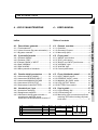
TIPO DI DOCUMENTO - Document type:
Descrizione generale e istruzioni
per l’installazione, l'attivazione,
l’uso e la manutenzione
General overview, instructions for
installing and starting up the Ups;
User manual.
EDIZIONE - Issue:
PRODOTTO - Product:
1
Gruppo statico di continuità On-line
a doppia conversione con by-pass
automatico.
On-line type uninterruptible power
supply unit with double conversion
and automatic by-pass.
MODELLO - Model UPS 60 ÷ 120 KVA
ANNO DI COSTRUZIONE - Manufacturing Date:
CONFORMITA’ - conformity:
Marchio CE
2002
CE BRAND
APPLICAZIONI PER "SUPPORTO VITA"
A causa della varietà delle applicazioni e delle normative applicabili in ciascun caso, non raccomanda la vendita di
questo prodotto per un utilizzo non perfettamente consapevole. La responsabilità di applicazioni ove un malfunzionamento o
l'inadeguatezza dell'UPS portino al rischio della vita umana sarà a carico dell'acquirente. non accetta responsabilità per danni conseguenti a tali applicazioni.
LIFE SUPPORT APPLICATIONS
Due to the variety of applications and involved standards in each case , does not recommend or knowingly
sell it's product for any use not perfectly conscious.Applications where UPS malfunctions or inadequacy give rise to risk
of human life shall be sole responsibility of the purchaser. accepts no liability for consequential harm in
such applications .
I dati contenuti nel presente manuale sono dati dal Costruttore, con riserva di modificarli in ogni momento senza preavviso.
Information in this handbook are given by the Manufacturer which reserves the right to modify them without any notice.
UPS 60 -120 kVA ATLAS Manuale tecnicoDT0342 ediz. 00 - Technical handbook DT0342 Issue 00
INDICE GENERALE
CONTENTS
PREMESSA
FOREWORD
A.1.
A.2.
A.3.
A.4.
A.5.
A.1.
A.2.
A.3.
A.4.
A.5.
Pronto soccorso ..................................... V
Norme di sicurezza ............................... VI
Istruzioni di sicurezza ........................... IX
Demolizione e smaltimento ................... X
10 domande frequenti (FAQ) ................ XI
First Aid .................................................. V
Safety requirements ............................. VI
Safety instructions ................................ IX
Demolition and sell off ........................... X
10 Frequently asked questionsFAQ) .. XI
1. - INFORMAZIONI GENERALI
1. - GENERAL OVERVIEW
1.1. Descrizione generale dell'UPS .............. 2
1.2. Configurazioni ed equipaggiamenti
opzionali .................................................. 4
1.3. Principio di funzionamento ..................... 8
1.1. UPS general description ........................ 5
1.2. Configuration and optional
equipment................................................ 7
1.3. Operation ................................................. 8
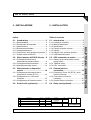
2. - INSTALLAZIONE
2. - INSTALLATION
2.1.
2.2.
2.3.
2.4.
2.5.
2.1.
2.2.
2.3.
2.4.
2.5.
Introduzione ............................................. 3
Allacciamento dell'UPS alla rete ............ 8
Allacciamento a dispositivi esterni ...... 14
Scheda Relè (opzionale) ...................... 17
Allacciamento provvisorio per la ricarica
delle batterie .......................................... 18
Introduction ............................................. 3
UPS connection to mains ...................... 8
External devices connection ............... 14
Relay card (optional) ............................ 17
Temporary connection to enable
battery recharge ................................... 18
3. - ATTIVAZIONE
3. - SETUP
3.1. Prima accensione e verifiche ................ 3
3.2. Predisposizioni ....................................... 7
3.3. Attivazione dei dispositivi periferici ...... 11
3.1. Initial turn-on and checks ....................... 3
3.2. Setting options ........................................ 7
3.3. Pheripheral device set-up ...................... 9
Rev
Descrizione
Data
Controllato
Realizzato
U.T. PTX
Data
Tipo di doc.
Pagine n°
Pag. totali
10/01/2003
Approvato
Cod.
DT0342-E00
Indice generale/Table of contents - I
INDICE GENERALE - CONTENTS
I
UPS 60 -120 kVA ATLAS Manuale tecnicoDT0342 ediz. 00 - Technical handbook DT0342 Issue 00
I
4. - USO E MANUTENZIONE
4. - USER MANUAL
4.1.
4.2.
4.3.
4.4.
4.5.
4.6.
4.7.
4.8.
4.9.
4.1.
4.2.
4.3.
4.4.
4.5.
4.6.
4.7.
4.8.
4.9.
4.10.
INDICE GENERALE - CONTENTS
Descrizione generale ............................. 3
Il pannello frontale ................................... 5
Quadro elettrico posteriore .................. 14
Istruzioni per l'uso ................................. 15
Uso con il PC ........................................ 20
Pannello remoto (opzionale) ................ 21
Manutenzione ordinaria ........................ 22
Manutenzione periodica ....................... 23
Stati dell'UPS (funzionamento
normale)................................................25
4.10. Risoluzione dei problemi ...................... 27
II - Indice generale/Table of contents
General overview .................................... 3
Front panel .............................................. 5
Rear distribution panel ......................... 14
User’s guide .......................................... 15
Use with the PC .................................... 20
Remote panel (optional) ....................... 21
Routine maintenance ........................... 22
Periodic maintenance ....................... 23
UPS status (normal mode)..................25
Troubleshooting .................................... 27
UPS 60 -120 kVA ATLAS Manuale tecnicoDT0342 ediz. 00 - Technical handbook DT0342 Issue 00
PREMESSA
FOREWORD
A.1. Pronto soccorso .......................... V
A.1. First aids ....................................... V
Spegnimento in emergenza ................... V
Persone colpite da scarica elettrica ...... V
Persone venute in contatto con liquidi
corrosivi ................................................... V
Persone che hanno ingerito liquidi
corrosivi ................................................... V
Emergency Power Off ........................... V
First aids for electric shock .................. V
People contaminated by corroding
liquids ...................................................... V
People having ingested corroding
liquids ...................................................... V
A.2. Norme di sicurezza ..................... VI
A.2. Safety rules .................................. VI
Carico sul pavimento del locale di
installazione ........................................... VI
Accesso ai locali .................................... VI
Dimensioni dei locali .............................. VI
Ventilazione ............................................ VI
Usi consentiti .......................................... VI
Surriscaldamento ................................. VII
Precauzioni elettriche ........................... VII
Arresto in emergenza ........................... VII
Batterie .................................................. VII
Guanti protettivi .................................... VIII
Tappeto isolante...................................VIII
Spogliarsi degli oggetti di metallo ........ VIII
Non fumare .......................................... VIII
Assistenza ........................................... VIII
Informazione del personale ................. VIII
Maximum load
on the floor ............................................ VI
Room accessibility ............................... VI
Room dimensions ................................ VI
Ventilation .............................................. VI
Allowed use ........................................... VI
Overheating ......................................... VII
Electrical caution ................................. VII
Emergency Power Off ......................... VII
Batteries ............................................... VII
Protective gloves ................................ VIII
Isolating carpet ................................... VIII
Strip metal objects .............................. VIII
Do not smoke ..................................... VIII
Technical support ............................... VIII
Personnel info ..................................... VIII
A.3. Istruzioni di sicurezza ................ IX
A.3. Safety instruction ........................ IX
Prima di fare l'installazione ................... IX
Installazione ........................................... IX
Before starting installation .................... IX
Installation ............................................. IX
Rev
Descrizione
Data
Controllato
Realizzato
U.T. PTX
Data
Tipo di doc.
Pagine n°
Pag. totali
10-01-2003
Approvato
Cod.
DT0342-E00
Premessa/Foreword - III
PREMESSA- FOREWORD
A
UPS 60 -120 kVA ATLAS Manuale tecnicoDT0342 ediz. 00 - Technical handbook DT0342 Issue 00
A
Earth connection ................................... IX
Earth leakage protection ...................... IX
In case of fire ........................................ IX
Personnel training ................................. IX
A.4. Demolizione e smaltimento ......... X
A.4. Dismantling and disposal ............ X
Smaltimento dell'imballaggio ................. X
Smaltimento delle parti metalliche ........ X
Smaltimento delle schede elettroniche . X
Smaltimento delle batterie ..................... X
Smaltimento di ulteriori parti .................. X
Disposal of packing ............................... X
Disposal of metal parts ......................... X
Disposal of electronic cards ................. X
Disposal of batteries .............................. X
Disposal of other parts .......................... X
A.5. 10 domande frequenti (FAQ) ...... XI
A.5. F.A.Q. ............................................ XI
PREMESSA- FOREWORD
Collegamento di terra ............................ IX
Protezione differenziale ......................... IX
In caso di incendio ................................. IX
Addestramento del personale ............... IX
IV - Premessa/Foreword
UPS 60 -120 kVA ATLAS Manuale tecnicoDT0342 ediz. 00 - Technical handbook DT0342 Issue 00
A
PRONTO SOCCORSO
A.1. FIRST AIDS
Spegnimento in emergenza
Emergency Power Off
In caso di emergenza, è possibile interrompere l'alimentazione al carico aprendo
tutti gli interruttori ubicati nella parte frontale inferiore dell'UPS dietro la porta.
In an emergency case, the load supply
can be disconnected opening all the lever
switches fitted in the front lower side of the
UPS, opening the door.
Persone colpite da scarica elettrica
First aids for electric shock
Sezionare l'alimentazione, oppure utilizzare un materiale isolante asciutto per
proteggersi mentre si sposta l'infortunato
lontano da qualsiasi conduttore.
EVITARE DI TOCCARE L'INFORTUNATO CON LE MANI NUDE FINO A CHE
QUEST'ULTIMO NON SIA LONTANO DA
QUALSIASI CONDUTTORE. CHIEDERE
lMMEDIATAMENTE L'AIUTO DI UNA PERSONA QUALIFICATA E ADDESTRATA.
Turn off or open the power supply line, or
use an isolated dry material to protect itself
while moving the victim far away from any
electrical cable.
DO NOT TOUCH THE VICTIM WITH
HANDS UNTIL THE LATTER IS FAR
AWAY FROM ANY ELECTRIC WIRE.
SEEK IMMEDIATELY FOR MEDICAL
HELP.
Persone venute in contatto con liquidi corrosivi
People contaminated by corroding
liquids
Qualora l'elettrolito delle batterie venisse
in contatto con la pelle, sciacquare abbondantemente con acqua la zona di pelle
interessata; togliere i vestiti contaminati;
ricoprire le bruciature con garza asciutta.
Qualora l'elettrolito delle batterie venisse
in contatto gli occhi, lavarli immediatamente con una soluzione d'acqua salina o
con acqua corrente per almeno 10 minuti.
Should the batteries electrolyte come into
contact with skin, rinse abundantly with
water the skin; remove the contaminated
clothes; apply dry gauze to the contaminated skin.
Should the batteries electrolyte come into
contact with eyes, wash them immediately
with a saline water solution or with fresh
water for 10 minutes at least.
Persone che hanno ingerito liquidi
corrosivi
People having ingested corroding liquids
Qualora l'elettrolito delle batterie venisse
ingerito, non provocare il vomito, ma consentire all'infortunato di bere acqua o latte
in grande quantità.
Should the batteries electrolyte ingested,
do not induce vomiting but let the victim
drink as much water or milk as he likes.
IN TUTTI I CASI CHIEDERE
IMMEDIATAMENTE
L'AIUTO DI UN MEDICO
AT ALL EVENTS SEEK
IMMEDIATELY
FOR MEDICAL HELP
Premessa/Foreword - V
PREMESSA- FOREWORD
A.1.
UPS 60 -120 kVA ATLAS Manuale tecnicoDT0342 ediz. 00 - Technical handbook DT0342 Issue 00
A
A.2. NORME DI SICUREZZA
A.2. SAFETY RULES
Carico sul pavimento del locale di
installazione
Maximum load on the floor
In considerazione dei pesi del sistema
UPS (Cap. 1.5 - Caratteristiche), è necessario scegliere un locale di installazione il
cui pavimento sia in grado di sostenere il
peso dell'apparecchiatura. In caso di problemi consultare il costruttore.
According to the weight of the UPS System (see chapt. 1.5 - Characteristics), the
installation site must have a floor capable
to carry the equipment weight. When in
doubt, consult the building firm.
Accesso ai locali
PREMESSA- FOREWORD
Il locale deve presentare uno spazio sufficiente a garantire i movimenti necessari
per l'installazione: le porte devono avere
una dimensione sufficiente a consentire
l'ingresso dell'apparecchiatura. Per muovere l'apparecchiatura utilizzarre un
transpallet in grado di sostenere il peso
dell'UPS.
Room accessibility
The room must be suitable to permit all
installation manoeuvres: consider the door
dimension in order to facilitate the passage of the equipment. For equipment
moving a transpallet capable to lift the
UPS weight is required.
Dimens. dei locali e i inquinamento.
Deve essere lasciato uno spazio sufficiente a garantire la corretta esecuzione
dei normali interventi di manutenzione. Tra
il tetto dell'UPS e il soffitto dei locali di
installazione deve essere presente uno
spazio di almeno 400 mm. Il locale deve
essere sufficientemente pulito e senza
polveri carboniose o conduttive. (grado di
inquinamento consentito 2)
Room dimensions and pollution
Ventilazione
Ventilation
La temperatura d'esercizio dell'UPS è compresa tra 0 °C e 40 °C. La temperatura
ambiente ideale non dovrebbe superare i
25 °C. Il calore prodotto dall'UPS viene
estratto da ventilatori interni e dissipato
nell'aria e può essere rimosso dal locale in
cui è installato l'UPS mediante un sistema
di ventilazione (raffreddamento forzato) o
un sistema ad aria condizionata.
The UPS working temperature is in the
range 0 °C to 40 °C. The ideal environmental temperature should not exceed 25 °C.
The UPS' heat is extracted by internal fans
and dissipated in the air; the heat can be
removed from the room in which the UPS
is installed by means of a fan system
(forced ventilation) or by an air conditioning system.
Usi consentiti
Allowed use
L'unità deve essere usata secondo le finalità previste. Seguire le istruzioni riportate
nel Cap. 4 - Istruzioni per l'uso.
The unit must be used as intended. Follow
the instructions given in Chapt. 4 - User's
Manual.
VI - Premessa/Foreword
All around the UPS a minimum free space,
enough to guarantee the correct execution
of maintenance jobs must be kept. Between the top of the UPS and the installation site ceiling the minimum distance must
be at least 400 mm.Room has to be clean
and without conductive dusts.(max pollution degree 2)
UPS 60 -120 kVA ATLAS Manuale tecnicoDT0342 ediz. 00 - Technical handbook DT0342 Issue 00
Surriscaldamento
Overheating
Per impedire il surriscaldamento, non
ostruire il flusso dell'aria dalle apposite
aperture dell'unità.
NON appoggiare oggetti sul tetto
To prevent overheating do not obstruct the
ventilation openings for flow of air of the
unit.
DON'T leave objects on the top of the unit.
Precauzioni elettriche
Electrical caution
All'interno dell'unità sono presenti tensioni
pericolose.
Non aprire l'unità e gli armadi ausiliari: i
componenti all'interno dell'unità non possono essere riparati dall'utente.
NON devono inoltre essere rimossi i coperchi protettivi dall'interno dell'armadio
UPS.
Dangerous voltage is present inside the
unit.
The User must not open the Ups cabinet
or auxiliary cabinets: the components inside the unit are not repairable by the User.
Moreover, do not remove any protective
covers from inside the Ups cabinet.
Tutti gli interruttori generali installati a
monte dell'UPS devono recare la seguente dicitura: “Isolare l'UPS (Gruppo di continuità) prima di lavorare su questo circuito”.
Arresto in emergenza
L'unità è munita di E.P.O. (Emergency
Power Off - arresto di emergenza). Questa funzione viene attivata premendo il
pulsante di emergenza esterno al quale è
stata collegata. Essa prevedel'estinzione
della tensionesul carico e l'arresto
dell'inverter. Saranno ancora presenti tensioni pericolose all'interno dell'unità (condensatori carichi) aspettare 5 minuti prima
di agire sull'unità.
Batterie
Durante l'elettrolisi, le batterie rilasciano
gas idrogeno. Esiste il rischio di esplosione se la quantità di idrogeno nella stanza
batterie diviene eccessiva. Garantire
un'adeguata ventilazione del locale batterie in conformità allo Standard EN50091 1, per evitare il rischio di esplosione.
Se la temperatura media supera i 25 °C si
riduce la durata della batteria. Il rapporto è
generalmente 1/2 durata per un incremen-
Allprim ary power switches installed upstream of the Ups m ustbe labelled as
follows:“IsolateUPS Uninterruptible Power
Supply) before working on this circuit”.
Emergency Power Off
The unit is provided with the E.P.O. (Emergency Power Off). This function is activated by pressing the external emergency
button to which the Ups has been connected. This function provides Ups disconnection from the load and from the
battery.
Dangerous voltage will still be present inside the unit, (charged capacitors) wait for
5 minutes before working on the unit.
Batteries
During electrolysis, batteries release hydrogen gas. There is a risk of an explosion
if the amount of hydrogen in the battery
room becomes too high. Ensure appropriate ventilation of the battery room according to the Standard EN50091 -1, to prevent
the risk of an explosion.
If the average temperature in the room
exceeds 25 °C the battery lifetime is greatly
reduced. The lifetime is reduced of 1/2 for
10 °C temperature raising. The ideal temperature should range from 15 to 25 °C.
Premessa/Foreword - VII
PREMESSA- FOREWORD
A
UPS 60 -120 kVA ATLAS Manuale tecnicoDT0342 ediz. 00 - Technical handbook DT0342 Issue 00
A
to di 10 °C. La temperatura ambiente ideale è compresa tra i 15 °C e i 25 °C.
PREMESSA- FOREWORD
Le batterie installate, se integre, si presentano asciutte e nessun liquido corrosivo
esce dal contenitore.
In caso di urto accidentale ispezionare le
batterie !
Un contenitore rotto può lasciare uscire
l'elettrolito che può causare bruciature sulla
pelle e corrodere metalli, vernici e tessuti o
provocare contatto tra le parti interne e
l'elettrolito.
The installed battery, when in good condition, looks dry and no corrosive liquid
drops out its case.
In case of accidental crash inspect accurately the batteries !
A broken case can the electrolyte drops
out; the latter can cause burns of the skin,
corrode metal cabinet, finishing coating
and fabrics or cause short-circuiting among
the internal parts and the electrolyte.
Protective gloves
Guanti protettivi
When handling damages batteries it is
mandatory to wear protective gloves.
Usare guanti di gomma se si opera su
batterie danneggiate.
Isolating carpet
Tappeto isolante
While working on the UPS, stand on a
rubber carpet and use isolated tools only.
Operando sull'UPS, stare su un tappeto di
gomma e usare soltanto attrezzi isolati.
Strip metal objects
Spogliarsi degli oggetti di metallo
Operando sull'UPS, togliersi tutti gli oggetti
personali: anelli, orologi, penne, ecc. che
possono causare cortocircuiti durante il
lavoro sulle batterie. Le batterie sono sempre attive ed un loro cortocircuito può fondere metalli e causare danni notevoli.
Non fumare
Operando sull'UPS, NON FUMARE o non
usare fiamme libere, ed evitare di creare
archi lavorando sull'UPS; non vestire abiti
che possono generare elettricità statica.
While working on the UPS, strip all personal objects: ring, watch, steel pen, etc.
which can cause short-circuiting when
working on batteries. The batteries are
always on and, if short circuited they can
fuse metals and cause many damages.
Do not smoke
While working on the UPS, DO NOT
SMOKE, do not use flames, avoid to create electric arcs when working on the UPS;
do not wear clothes that can create static
charges.
Assistenza
Technical support
L'assistenza su questa apparecchiatura
deve essere eseguite da personale qualificato.
This equipment must be serviced by qualified personnel.
Informazione del personale
A tutto il personale che si accinge ad
operare sull'UPS, sia esso specializzato o
meno, deve essere fatta prtendere visione
delle presenti Norme e Istruzioni.
VIII - Premessa/Foreword
Personnel Info
All the personnel operating on the UPS,
specialized or not, have to be acquainted
with all these Safety Instruction.
UPS 60 -120 kVA ATLAS Manuale tecnicoDT0342 ediz. 00 - Technical handbook DT0342 Issue 00
A
Prima di fare l'installazione
Aprire gli interruttori INPUT MAINS, INPUT
RESERVE, MANUAL BY-PASS e OUTPUT
(tutte le levette devono essere orizzontali)
per isolare completamente l'apparecchiatura; l'alimentazione di ingresso e l'eventuale batteria esterna devono essere isolate dall'UPS.Togliere i fusibili dell'armadio
batterie esterno e / o aprire il sezionatore
di batteria.
Installazione
L'installazione di questa apparecchiatura
deve essere eseguite da personale qualificato, secondo le informazioni date nel
Cap. 2 - Installazione.
Alta corrente di dispersione verso
terra
Prima di collegare i cavi di alimentazione
collegare la protezione di terra.
Protezione differenziale
Questo dispositivo ha un'alta corrente di
dispersione verso la terra di protezione. La
corrente massima di dispersione a terra è
di 300mA. Nel tarare la soglia dell'interruttore di dispersione a terra installato a monte di questa apparecchiatura, tenere presente questo contributo di corrente e quello dovuto ai carichi. si consiglia l'installazione di un dipositivo da almeno 500mA.
A.3. SAFETY INSTRUCTION
Before starting installation
To completely isolate the equipment, the
switches ON/OFF, INPUT, MANUAL BYPASS e OUTPUT must be switched off (all
the lever-switches orizontal) the input supply and external battery supply should be
isolated from the UPS. Remove all the
fuses in the Auxiliary Battery cabinet and/
or open battery isolator.
Installation
This equipment must be installed by qualified personnel, following instruction given
in chapter 2 - Installation.
High leakage current
Connect protective earth before power
supply cables.
Earth leakage protection
This device has a high leakage current
towards protective earthing. The maximum
earth leakage current is 300 mA. When
setting the threshold of the earth leakage
circuit breaker installed upstream from
this equipment consider this amount of
current and the current amount due to the
loads.It is suggested to install a protection
device of at least 500mA.
In case of fire
In caso di incendio
All'interno del Sistema di Continuità sono
presenti tensioni pericolose, anche con
tutti gli interruttori aperti!
Pertanto in caso di incendio nei locali d'installazione non utilizzare acqua per lo spegnimento del fuoco.
Inside the Uninterruptible Power Supply
unit dangerous voltage is present, even if
all the switches are off !
For this reason in case of a fire:
do not use water
to put out a fire.
Personnel training
Addestramento del personale
Tutto il personale deve essere addestrato
ad eseguire lo spegnimento in emergenza
(vedere 1. Pronto soccorso)..
All personnel operating on the UPS have
to be trained to perform the Emergency
Power Off (see A.1. - First Aids).
Premessa/Foreword - IX
PREMESSA- FOREWORD
A.3. ISTRUZIONI DI SICUREZZA
UPS 60 -120 kVA ATLAS Manuale tecnicoDT0342 ediz. 00 - Technical handbook DT0342 Issue 00
A
PREMESSA- FOREWORD
A.4.
DEMOLIZIONE E SMALTIMENTO
A.4. DISMANTLING AND DISPOSAL
In caso di demolizione dell'UPS, le parti di cui
è composto devono essere affidate a ditte
specializzate nello smaltimento e riciclaggio
dei rifiuti industriali e, in particolare:
Should the UPS be dismantled, the parts making
it up must be assigned to Companies specialised in the disposal and recycling or industrial
waste, specifically:
Smaltimento dell'imballaggio
Disposal of packing
L'imballaggio è costituito da materiale biodegradabile e può essere consegnato a normali
aziende di recupero della cellulosa.
Packing consists of biodegradable material. The
cardboard can be sent to Companies assigned
to recuperating cellulose.
I profili protettivi in poliuretano espanso sono
chimicamente inerti e possono essere smaltiti in
discariche dove non contribuiscono nè alla formazione di gas nè all'inquinamento delle acque
di infiltrazione.
Polyurethane foam protective profiles are chemically inert, they do not contribute to gas forming
nor to pollute water; their disposal can be assigned to Companies specialised in the disposal
of industrial materials.
Smaltimento delle parti metalliche
Disposal of metal parts
Le parti metalliche del mobile, sia quelle verniciate, sia quelle in acciaio sono normalmente
recuperabili dalle aziende specializzate del settore di rottamazione dei metalli.
The metal parts of the cabinet, both the varnished ones and the stainless steel ones, are
regularly recovered by companies specialised
in the scrapping of metals.
Smaltimento delle schede elettroniche
Disposal of electronic cards
Le schede elettroniche devono obbligatoriamente essere smaltite da aziende specializzate nello
smaltimento di componenti elettronici.
It is mandatory that the electronic cards be
disposed of companies specialised in the disposal of electronic components.
Smaltimento delle batterie
Disposal of batteries
Le batterie devono essere separate da tutte le
altre parti dell'UPS e smaltite secondo le norme
che regolano lo smaltimento di rifiuti tossici e
nocivi.
Batteries must be separated from any other part
of the UPS and disposed according to the norms
locally current about disposal of toxic and noxious industrial materials.
Smaltimento di ulteriori parti
Disposal of other parts
Ulteriori parti costituenti l'UPS, come guarnizioni
in gomma, parti in plastica e cablaggi, sono da
affidare a ditte specializzate nello smaltimento di
rifiuti industriali.
The disposal of other parts making up the UPS,
i.e., rubber gaskets, plastic materials and wiring
is assigned to Companies specialised in the
disposal of industrial materials.
X - Premessa/Foreword
UPS 60 -120 kVA ATLAS Manuale tecnicoDT0342 ediz. 00 - Technical handbook DT0342 Issue 00
A
A.5. 10 DOMANDE FREQUENTI (FAQ)
A.5. F.A.Q.
Come installare l'UPS ?
Per installare l'UPS consultare:
- Cap. 2 - Installazione.
How have you to install your UPS?
Refer to the instructions supplied in the following
documents:
- Chapt. 2 - Installation.
Per installare l'armadio trasformatore consultare:
- Allegato 2 : Armadio trasformatore.
Personale richiesto: tecnici elettricisti
To install the Battery Cabinet see the document:
- Annex 1 : Battery cubicle
To install the Transformer Cabinet see the
document:
- Annex 2 : Transformer Cabinet
Personnel required: fitters/electricians
Per tutte le altre volte, consultare:
- Cap. 4 - Uso e manutenzione, § 4.4.
Personale richiesto: generico
Where to find instructions to place UPS into
operations?
The first time, refer to the instructions supplied in
the following documents:
- Chapt. 3 - Setup.
Personnel required: Final test technicians
The following times, refer to the following:
- Chapt. 4 - User manual, § 4.4.
Personnel required: anyone can do that.
Devo fare manutenzione all'UPS ?
La manutenzione è estremamente ridotta, consultare:
Cap. 4.7: Manutenzione ordinaria
How to make the UPS maintenance ?
Refer to the instructions supplied in the following
documents:
Chapt. 4.7: Routine Maintenance
Personale richiesto: generico
Personnel required: anyone can do that.
Le batterie sono scariche, che fare ?
Consultare:
Cap. 2.5.1: come ricaricare le batterie
The battery is low, what to do ?
Refer to the following documents:
Chapt. 2.5.1: Battery recharging
Personale richiesto: generico
Personnel required: anyone can do that.
Vorrei addestrare tutto il personale alle operazioni più semplici sull'UPS, che fare ?
Svolgere un rapido corso di addestramento sugli
argomenti trattati nei seguenti capitoli:
PREMESSA
Cap. 4 - Uso e manutenzione
The personnel should be upgraded on the
simplest UPS's commands, how to do?
Have a short training about these two followings:
Personale richiesto: per tutti
Personnel required: anyone can do that.
Come mettere in funzione l'UPS ?
Se l'UPS viene acceso per la prima volta,
consultare:
- Cap. 3 - attivazione.
Personale richiesto: tecnici collaudatori
-
FOREWORD
Chapt. 4 - User manual
Premessa/Foreword - XI
PREMESSA- FOREWORD
Per installare l'armadio batterie consultare:
- Allegato 1 : Armadio batterie .
UPS 60 -120 kVA ATLAS Manuale tecnicoDT0342 ediz. 00 - Technical handbook DT0342 Issue 00
PREMESSA- FOREWORD
A
L'UPS è guasto, che fare ?
Consultare le istruzioni fornite nel:
Cap. 4.4.3: Inserimento del By-pass manuale e spegnimento dell'UPS senza interruzione di alimentazione al carico.
Cap. 4.8: Risoluzione dei problemi.
The UPS is failed, what to do ?
Refer to the following documents:
Chapt. 4.4.3: Manual by-pass connection
and UPS switching OFF without cutting off
power to the load.
Chapt. 4.8: Troubleshooting.
Personale richiesto: tecnici generici.
Personnelrequired:supporttechnician.
Come usare il PC collegato all'UPS ?
Consultare il manuale fornito a corredo del programma UPS MANAGEMENT SOFTWARE.
How to use the PC connected to the UPS ?
Refer to the instructions supplied with the UPS
MANAGEMENT SOFTWARE.
Personale richiesto: personale con esperienza
nell'uso di strumenti informatici.
Personnel required: experienced with Personal
Computers and relevant applications.
Cosa significano le spie del Pannello remoto
Consultare:
- Cap. 4 - Uso e manutenzione, § 4.6
What do the Remote panel lamps mean ?
Refer to the following documents:
- Chapt. 4 - User manual, § 4.6
Personale richiesto: generico
Personnel required: anyone can do that.
Come fare in caso di allarme?
Consultare:
- Cap. 4.8 - Risoluzione dei problemi
How to proceed when the UPS is alarmed ?
Refer to the following documents:
- Chapt. 4.8 - Troubleshooting
Personale richiesto: generico
Personnel required: support technician.
Per avere informazioni di tipo tecnico-commerciale sull'UPS
Consultare :
- Cap. 1 - Informazioni generali e caratteristiche tecniche.
How to gain informations of the technicalcommercial type about the UPS
Refer to the following documents:
- Chapt. 1 - General Overview
XII - Premessa/Foreword
UPS 60 -120 kVA ATLAS Manuale tecnicoDT0342 ediz. 00 - Technical handbook DT0342 Issue 00
1 - INFORMAZIONI GENERALI
1 - GENERAL OVERVIEW
Indice
Table of contents
1.1. Descrizione generale dell'UPS .... 2
1.1. UPS general description ............... 2
1.1.1. Campi di utilizzazione dell'UPS ............2
1.1.2. Potenza e autonomia ............................2
1.1.3. Sicurezza e facilità d’uso ......................3
1.1.4. Particolari costruttivi .............................. 3
1.1.1. UPS type of application ........................2
1.1.2 Power and autonomy ............................. 2
1.1.3. Safety and ease of use ......................... 3
1.1.4. Construction details .............................. 3
1.2. Configurazioni e equipaggiamenti
opzionali ........................................ 4
1.2. Configuration and optional
equipment ...................................... 4
1.2.1. Configurazioni di base ..........................4
1.2.2. Armadio batterie ....................................5
1.2.3. Armadio trasformatore ..........................5
1.2.4. Accessori ..............................................6
1.2.1. Base configuration ...............................4
1.2.2. Batteries cabinet ...................................5
1.2.3. Transformer cabinet .............................. 5
1.2.4.Accessories .......................................... 6
1.3. Principio di funzionamento .......... 7
1.3. Operation ....................................... 7
1.3.1. Stadio di ingresso, modulo di potenza e
stadio di uscita ......................................7
1.3.2. Schema funzionale dell'UPS (doppia
conv. con by-pass) ................................ 8
1.3.3. Logica e circuiti ausiliari ........................9
1.3.4. Batterie ................................................ 10
1.3.5. Scheda Relè ....................................... 10
1.3.6. By-pass manuale ................................ 10
1.3.7. Pannello frontale ................................. 11
1.3.1. Input Stage, Power Module and Output
Stage .....................................................7
1.3.2. UPS functional drawing (double conversion/by-pass) ........................................8
1.3.3. Logic and Auxiliary circuits ...................9
1.3.4. Batteries .............................................. 10
1.3.5. Relay card .......................................... 10
1.3.6. Manual by-pass .................................. 10
1.3.7. Front panel .......................................... 11
Rev
Descrizione
Data
Controllato
Realizzato
U.T. PTX
Data
Tipo di doc.
Pagine n°
Pag. totali
20-04-2002
Approvato
Cod.
DT0342-E00
Informazioni generali/General overview-1- 1
INFORMAZIONI GENERALI - GENERAL OVERVIEW
1
UPS 60 -120 kVA ATLAS Manuale tecnicoDT0342 ediz. 00 - Technical handbook DT0342 Issue 00
INFORMAZIONI GENERALI - GENERAL OVERVIEW
1
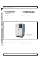
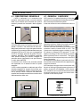
1.1. DESCRIZIONE GENERALE
DELL'UPS
1.1. UPS GENERAL
DESCRIPTION
Le ridotte dimensioni esterne del contenitore
nascondono la notevole potenza dell'UPS: l’apparato, che si presenta con una moderna linea è
costituito da una struttura portante in lamiera
zincata, montata su ruote che ne agevolano i
brevi spostamenti; la struttura portante è coperta
da un mantello esterno in lamiera accuratamente verniciata.
The small outer size of the cabinet hides the
extraordinary power of UPS. The equipment has
a modern structure. It consists of a galvanized
steel iron supporting structure mounted on wheels
so as to easily move it around in the room. The
supporting structure is covered with a varnished
steel shell.
1.1.1. Campi di utilizzazione dell'UPS
1.1.1. UPS type of application
Il nuovo UPS è progettato per fornire alimentazione stabilizzata e filtrata a sofisticate
apparecchiature elettroniche (in particolare a
sistemi per l’elaborazione dei dati) alle quali deve
essere garantita una sorgente di alimentazione
esente da fluttuazioni di tensione e frequenza,
quindi ospedali, stazioni di polizia, gallerie autostradali, stazioni radioemittenti, banche, uffici
tecnici e amministrativi e molte altre applicazioni.
The latest UPS is an uninterruptible assembly
designed to deliver stabilized and filtered power
to sophisticated electronic equipment (data
processing systems). Since the latter are normally utilized in medical centers, police stations,
motorway tunnels, broadcasting stations, banks,
technical and administrative offices and other
applications they must guarantee a power source
free from voltage and frequency variations.
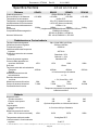
1.1.2. Potenza e autonomia
1.1.2 Power and autonomy
Grazie alla progettazione modulare l'UPS è disponibile nelle versioni con potenza nominale da
60kVA a 120kVA, tutte con cos ϕ = 0,8.
Tutte le taglie non hanno batteria all'interno, ed è
previsto l'utilizzo di armadio batteria separato
per qualunque autonomia.
The modular design of UPS allows to supply it in
versions featuring a nominal power from 60kVA
to 120kVA, all with cos ϕ = 0,8.
All versionas have not battery inside, an external
battery cubicle has to be provided for each
autonomy.
1.1.3. Sicurezza e facilità d’uso
1.1.3. Safety and ease of use
Tutti i comandi disponibili sono perfettamente
isolati e disaccoppiati da elevate tensioni di lavoro, così come è stata posta estrema attenzione
all’isolamento e separazione galvanica riservata
alle parti esterne del contenitore.
All the controls available are perfectly isolated
and decoupled from the high working voltages,
likewise for the outer parts of the container which
have been carefully isolated and galvanically
separated .
1 - 2 - Informazioni generali/General overview
UPS 60 -120 kVA ATLAS Manuale tecnicoDT0342 ediz. 00 - Technical handbook DT0342 Issue 00
Controlli sia sul sovraccarico che sulla sovratemperatura garantiscono l’immediato e più opportuno intervento nel caso che una di queste
condizioni si verifichi durante il funzionamento.
E’ possibile il collegamento di uno o più pulsanti
di emergenza (non forniti ) che in caso di incendio permettano di comandare la totale disattivazione dell’UPS.
Poichè il funzionamento dell'UPS è completamente automatico non c'è bisogno di dare comandi, perciò il pannello frontale è estremamente semplice e ha la sola funzione di verificare il
corretto funzionamento a intervalli periodici.
Il monitoraggio dell'UPS può essere gestito con
la massima semplicità tramite un personal computer ed un apposito programma di comunicazione (opzionale).
Un pannello remoto (opzionale) per il controllo
a distanza può essere collegato all'UPS; il pannello remoto si rivela indispensabile quando l’UPS
è installato in locali non sorvegliati: visualizza il
modo di funzionamento, ripete gli allarmi con
l’accensione di LED e l’attivazione di un allarme
sonoro.
Checks have been made both on overload and
on overtemperature to guarantee a prompt and
fitting intervention should one of the aforementioned conditions arise during operation.
One or more emergency push-buttons (not supplied) can be connected. These, in case of fire,
fully de-activate the UPS.
Since UPS operates in an automatic mode,
there is no need to forward commands.
Therefore, the front panel is extremely easy and
operation is the sole function to have a periodical
check.
UPS is easily managed through a personal computer and through an interacting program (optional).
A remote panel (optional) can be connected to
UPS for remote control operations.The remote
panel is considered essential when the UPS is
installed in unmanned rooms: it displays the
operating mode, repeats the alarms through the
lighting up of LEDs and activates a buzzer.
1.1.4. Particolari costruttivi
1.1.4. Construction details
Sulla parte frontale dell'UPS è posto il pannello di
comando.
Aprendo la porta, nella parte inferiore dell'UPS,
sono collocati i morsetti degli interruttori che
sono anche i terminali ingresso e uscita di potenza della macchina.
L'ingresso cavi può essere realizzato dal basso
o dall'alto.
The control panel is placed on the front door.
Behind the door, in the lower part of the
cubille, I/0 power switches terminals are also
I/0 connectors for over power cables.
Power cables inlet i s provided from the top
or from the bottom of the cubicle.
Informazioni generali/General overview-1- 3
INFORMAZIONI GENERALI - GENERAL OVERVIEW
1
UPS 60 -120 kVA ATLAS Manuale tecnicoDT0342 ediz. 00 - Technical handbook DT0342 Issue 00
INFORMAZIONI GENERALI - GENERAL OVERVIEW
1
1.2. CONFIGURAZIONI E
EQUIPAGGIAMENTI
OPZIONALI
1.2. CONFIGURATION AND
OPTIONAL EQUIPMENT
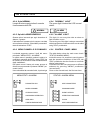
1.2.1. Configurazioni base
1.2.1. Base configuration
Configurazione base
Base configuration
La configurazione base prevde l'UPS trafoless
nel proprio armadio.
Le batterie sono escluse
1 - 4 - Informazioni generali/General overview
The base configuration provides trafoless
UPS equipped in its cubicle.
Batteries aren't provided.
UPS 60 -120 kVA ATLAS Manuale tecnicoDT0342 ediz. 00 - Technical handbook DT0342 Issue 00
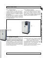
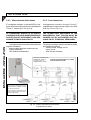
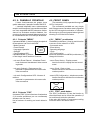
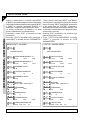
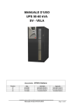
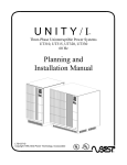
1.2.2. Armadio batterie
1.2.2. Batteries cabinet
Ove richiesto l'UPS può essre fornito
completo di batterie per l'autonomia richiesta.
Le batterie possono esere alloggiate in armadio
di dimensioni opportune, completo di organi di
sezionamento.
Nel caso di batterie non installate in prossimità
dell'UPS deve essere previsto un opportuno
quadretto di sezionamento a parete, da installare
in prossimità dell'UPS
UPS can be supplied with a suitable battery
cabinet for the required autonomy . Cabinet
contains also dc isolator to disconnect battery
when necessary.If battery location is not near
the UPS , a wall cabinet containing battery
isolator must be provided near UPS.
UPS
UPS
Armadio batterie
Batteries cabinet .
1.2.3. Armadio trasformatore
1.2.3. Transformer cabinet
E' disponibile un armadio opzionale con
trasformatore di isolamento galvanico per
impieghi specifici come, ad esempio, applicazioni
ospedaliere. Il trasformatore standard è trifase/
trifasecon rapporto 1:1, ma può essere fornito
con rapporto di trasformazione secondo richiesta.
Nello stasso armadio può essere equipaggiato
un trasformatore per la riduzione delle armoniche
di corrente assorbite da rete.
An optional cabinet with a galvanic isolating
transfomer is available and this is specifically utilized in medical centers.
The standard transformer features a three-phase/
three-phase with 1:1 ratio characteristic, (the
transformer ratio can be customized).
In the same cabinet could be equipped a suitable
transformer for line current armonic.
Informazioni generali/General overview-1- 5
INFORMAZIONI GENERALI - GENERAL OVERVIEW
1
UPS 60 -120 kVA ATLAS Manuale tecnicoDT0342 ediz. 00 - Technical handbook DT0342 Issue 00
1
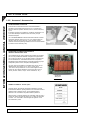
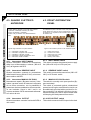
1.2.5. Accessori - Accessories
INFORMAZIONI GENERALI - GENERAL OVERVIEW
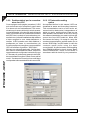
UPS MANAGEMENT SOFTWARE
Il software di comunicazione Generex “UPS MANAGEMENT”:
permette la comunicazione tra l'UPS e un PC o una rete di PC
basati su sistema operativo Windows, Win-NT, Novell, OS2, Dec,
Lynux.
Il software consente di controllare la condizione operativa di uno
o più UPS utilizzati per alimentare una rete locale (LAN) di
Personal Computer.
The “UPS MANAGEMENT” Generex interaction software : it allows
interaction between UPS and a PC or a PC network based on
Windows, Win-NT, Novel, OS2, Dec, Lynux operation system.
Software controls the operating condition of one or more UPS utilized
to power a local PC network (LAN).
SCHEDE PER LA COMUNICAZIONE REMOTA
REMOTE INTERACTING CARD
Una scheda Relè può essere aggiunta alla scheda relè standard,
per avere la possibilità di effettuare collegamenti supplementari
con un altro PC oppure con un pannello sinottico, inoltre dispone
di una morsettiera con contatti liberi da tensione che ripete le
segnalazioni sullo stato dell'UPS ed è in grado di pilotare ogni tipo
di dispositivo( allarmi sonori, lampade, telesegnalazioni).
An relay card can be added to a standard relay card to set up
additional links with another PC or with a remote panel,
this card is also provided with a cold contact tagblock which
reverts the UPS status indications and controls each type of
device (acoustic alarms, lamps, remote indications, etc.).
scheda relè
Relay card
PANNELLO REMOTO - Remote panel
Pannello remoto: permette di visualizzare a distanza il modo di
funzionamento dell'UPS, ripete gli allarmi con l’accensione di LED e
l’attivazione di un allarme sonoro. Viene collegato all'UPS
attraverso una morsettiera nel quadro elettrico posteriore.
Remote Panel: it remotely displays the operating mode of UPS, it
reverts the alarms through the lighting up of LEDs and activates
a buzzer. It is connected to UPS through the tagblock on the
rear distribution panel.
1 - 6 - Informazioni generali/General overview
UPS 60 -120 kVA ATLAS Manuale tecnicoDT0342 ediz. 00 - Technical handbook DT0342 Issue 00
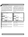
Il UPS è un gruppo di continuità del tipo On-line
a doppia conversione con by-pass automatico a
norma europea EN50091-1-3 (definizione ANIE:
Ups CIB). Tale tipo di UPS effettua, in maniera
continuativa e senza alcuna interruzione, una
doppia conversione della tensione in entrata.
La mancanza di collegamento diretto rete-carico
non consente il passaggio di alcun disturbo e la
doppia conversione garantisce in uscita
un'energia sempre rigenerata, sia in tensione
che in frequenza, ideale per il funzionamento di
utenze professionali.
Quando la tensione d'ingresso esce dalle
tolleranze ammesse, il carico viene alimentato
prelevando energia dalle batterie.
L'Utente dell'UPS si avvantaggia inoltre del bypass automatico: in caso di guasto o di
sovraccarico del gruppo di continuità il by-pass
connette le utenze direttamente alla rete elettrica
tramite una linea di riserva, consentendo così di
ripristinare le normali condizioni di lavoro senza
interruzioni di alimentazione al carico.
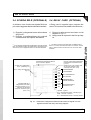
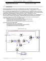
1.3.1. Stadio di ingresso, modulo di potenza e stadio di uscita
(Riferimenti: schema funzionale § 1.3.2.)
Dalla morsettiera di ingresso la rete viene inviata, tramite l'interruttore MAINS INPUT, al modulo
di potenza.
Il convertitore step-up si incarica della
conversione AC/DC della rete (condizione di
normale funzionamento) oppure della
conversione DC/DC dell'energia della batteria,
quando la rete è assente o fuori dalla tolleranza
consentita.
La corrente continua alimenta poi l'inverter che
ricostruisce l'alternata adeguando il prelievo in
funzione delle esigenze del carico.
Segue poi il by-pass automatico, anch'esso
pilotato dalla logica di controllo, che in condizioni
normali invia in uscita l'energia rigenerata e
filtrata del modulo di potenza.
1
1.3. OPERATION
UPS is an On-line type uninterruptible power unit
with double conversion and with automatic bypass compliant with the EN50091-1-3 (ANIE
definition: Ups CIB) European Standard.
Since there is no direct mains-load connection
there is no interference, and the double conversion guarantees a regenerated voltage and
frequency output power always; therefore, it is
ideally employed by professional users.
When the input voltage deviates from the allowed tolerance, the batteries will give the power
to deliver to the load.
The UPS User also makes use of the automatic
by-pass.
The presence of failure or of overload on the
uninterruptible power unit will cause the bypass to directly connect the user to mains through
a reserve line, thus restoring the regular operating conditions without loss of power to the load.
1.3.1. Input Stage, Power Module and Output Stage
(Reference: Functional drawing 1.3.2)
The mains voltage is delivered by the input
tagblock to the power module through switch
MAINS INPUT.
The step-up converter AC/DC converts mains
(regular operating condition) or DC/DC converts battery power when mains has either
failed or is not within the set tolerance.
The DC powers the inverter which reconstructs
the AC by adapting the power extracted vs. load
requirements.
An automatic by-pass follows driven by the
control logic. In regular operating conditions it
delivers the power module’s regenerated and
filtered power to the output.
As already stated, when a faulty or overload
condition arises, the automatic by-pass switches
over to the reserve line. In this manner the load
Informazioni generali/General overview-1- 7
INFORMAZIONI GENERALI - GENERAL OVERVIEW
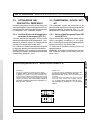
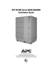
1.3. PRINCIPIO DI
FUNZIONAMENTO
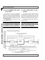
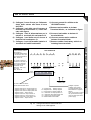
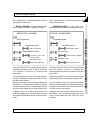
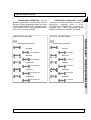
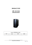
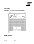
RESERVE
INPUT
By-pass line (Ups excluded)
Linea di By-pass (Ups escluso)
OUTPUT
Linea di riserva - Automatic by-pass
Convertitore step-up
step-up converter
3 F + N + PE
3PH+ N +PE
By-pass
automatico
automatic
By-pass
Inverter
MODULO DI POTENZA
POWER MODULE
MAINS
INPUT
CARICABATTERIA
BATTERY CHARGER
LOGICA PRINCIPALE DI CONTROLLO
MAIN CONTROL LOGIC
INTERFACCIA SEGNALAZIONI
SIGNALLING INTERFACE
NOTA - NOTE
Interruttori e contatti di relè sono
illustrati a Ups spento.
Switches and relay contacts shown
represent Ups in off state.
1.3..2. Schema funzionale dell'UPS (doppia conv. con by-pass)
UPS functional drawing (double conversion/by-pass)
SCHEDA
RELE'
RELAYS
BOARD
3 F + N + PE
3PH+ N +PE
ALIMENT. AUSIL.
AUX. CONVERTER
PANNELLO FRONTALE
FRONT PANEL
Ups in funzione
Ups run
By-pass inserito
By-pass on
Presenza rete 400 VCA
400 VAC mains presence
Batteria scarica
Battery low
al PC/Pannello remoto
to PC/Remote panel
comando E.P.O.
E.P.O. command
UPS 60 -120 kVA ATLAS Manuale tecnicoDT0342 ediz. 00 - Technical handbook DT0342 Issue 00
1 - 8 - Informazioni generali/General overview
ingresso rete
mains input
MANUAL
BY-PASS
1
INFORMAZIONI GENERALI - GENERAL OVERVIEW
UPS 60 -120 kVA ATLAS Manuale tecnicoDT0342 ediz. 00 - Technical handbook DT0342 Issue 00
Come già detto, in caso di avaria o di
sovraccarico, il by-pass automatico commuta
sulla linea di riserva: l'alimentazione al carico
viene così mantenuta dalla rete. Alla cessazione
delle cause che hanno provocato lo scambio
sulla linea di riserva, il by-pass ritorna
automaticamente all'alimentazione da inverter.
Tramite l'interruttore UPS OUTPUT, la rete 400
VCA filtrata, rigenerata e stabilizzata viene inviata al carico.
is still powered from mains.
When the cause that had produced switch-over
clears, the by-pass will automatically revert to
inverter powering.
The 400 Vac filtered, regenerated and stabilized
mains voltage is delivered through the UPS
OUTPUT switch to the load.
1.3.3. Logica e circuiti ausiliari
1.3.3. Logic and Auxiliary circuits
La logica di controllo risiede su un'apposita
scheda e rappresenta “l'intelligenza” dell'UPS.
Essa si incarica infatti di gestire il funzionamento del convertitore step-up, dell'inverter e del bypass in base al confronto in retroazione dei
segnali prelevati dal modulo di potenza. La
logica di controllo gestisce inoltre altre tre schede, cioè il caricabatteria, l'alimentatore ausiliario e l'interfaccia segnalazioni.
Il caricabatterie alimenta continuamente le batterie esterne collegate all'UPS. La scheda
caricabatteria è in grado di ricaricare le batterie
all'80% della capacità massima entro12 ore.
L'interfaccia segnalazioni preleva le segnalazioni
dalla Logica di controllo e le converte nel
protocollo previsto per il pannello frontale dell'UPS
e per la scheda Relè. A ritroso, i criteri provenienti
dal pannello frontale (forzatura by-pass
automatico) e/o dalla scheda Relè (EPO)
vengono inviati dall'interfaccia segnalazioni alla
Logica di controllo che lo interpreta
rispettivamente commutando sulla linea di riserva
e/o spegnendo immediatamente l'UPS.
L'interfaccia segnalazioni può alimentare, oltre
alla scheda Relè standard, anche un'altra scheda
opzionale (una seconda scheda relè).
L'alimentatore ausiliario provvede ad alimentare
la Logica di controllo, il pannello frontale e le
schede relè.
The control logic resides on a specific card and
represents the “smart” section of UPS. In fact, it
manages the operating mode of the step-up
converter, of the inverter and of the by-pass by
feed-back comparing the signals extracted from
the power module.
The control logic also manages three other
cards, i.e., the battery charger, the auxiliary
power supply unit and the signalling interface.
The battery charger uninterruptedly powers the
batteries connecting UPS.
The battery charger card can recharge up to
80% of the batteries maximum capacity within
12 hours.
The signalling interface extracts signalling from
the control logic and converts them into the
protocol specific for the front panel and for the
Relay card.
Likewise, the criteria inputting from the front
panel (automatic by-pass forcing) and/or from
the Relay card (EPO) are forwarded by the
signalling interface to the control logic where it will
be respectively interpreted, i.e., either switch
over to the reserve line and/or immediately switching off UPS.
Besides the standard Relay card the signalling
interface can also power an optional card (one
more relay card).
The auxiliary power unit feeds the Control Logic,
the front panel and relay cards.
Informazioni generali/General overview-1- 9
INFORMAZIONI GENERALI - GENERAL OVERVIEW
1
UPS 60 -120 kVA ATLAS Manuale tecnicoDT0342 ediz. 00 - Technical handbook DT0342 Issue 00
INFORMAZIONI GENERALI - GENERAL OVERVIEW
1
1.3.4. Batterie
1.3.4. Batteries
L'energia dalle batterie si presenta all'ingresso
del Convertitore step-up del modulo di potenza.
Quando la rete è presente, le batterie vengono
costantemente ricaricate dal modulo
caricabatteria.
The power delivered by the batteries reaches the
input of the step-up converter, situated on the
power module.
The batteries are continuously recharged by the
battery charger module when the mains is
present.
1.3.5. Scheda Relè
1.3.5. Relay card
La scheda relè esegue le medesime funzioni
della scheda standard ma, rispetto a
quest'ultima, dispone di una morsettiera con
contatti liberi da tensione, che ripete i medesimi
segnali del connettore DB9. Con la scheda Relè
è possibile(1) perciò pilotare, oltre a PC/Pannello
remoto, ogni tipo di dispositivo (allarmi sonori,
lampade, telesegnalazioni, ecc.).
The functions carried out by the relay card are
as those of the standard card except that, with
respect to the latter, it is provided with a cold
contact tagblock which repeats the same signals of the DB9 plug.
Therefore, the Relay card drives(1) not only a
PC/Remote Panel but also any other type of
device (e.g., acoustic alarms, lamps, remote
indications, etc.).
(1)
: non è possibile collegare alla scheda un secondo pulsante
EPO. Se occorre comandare lo spegnimento forzato dell'UPS
da più pulsanti EPO è necessario collegarli in serie tra loro e
collegare infine la serie all'ingresso di uno dei connettori CN3.
(1) : The card cannot be connected with an extra EPO button. If
the UPS has to be forced OFF through several EPO buttons,
then these should be series-connected and afterwards connected
to the input port of one of the CN3 plugs.
1.3.6. By-pass manuale
Il By-pass manuale è previsto per i casi in cui
occorra escludere l'UPS mantenendo alimentato
il carico da rete (es.: Ups fermo, avaria, ...). Si
tratta di un circuito azionabile tramite l’interruttore
MANUAL BY-PASS, che si trova nella parte
anteriore dell'UPS. L’interruttore, normalmente
aperto con levetta in posizione orizzontale, dispone di un fermo meccanico di protezione per
impedire che venga azionato inavvertitamente. Il
fermo meccanico è inoltre bloccabile con un
lucchetto per evitarne la rimozione da personale
non autorizzato.
1.3.6. Manual by-pass
The manual by-pass circuit is utilized in those
circumstances whereby it is necessary to exclude UPS while still keep load powered from
mains (e.g., Ups not running, failure, etc.). This
circuit can be operated through the MANUAL
BY-PASS switch located on the rear plane of
UPS. The switch, which is normally open with the
lever set to the orizontal position, is provided with
a protection stopper to prevent it from being
accidentally operated. The stopper can also be
pad-locked to prevent unauthorized personnel
from removing it.
1.3.7. Pannello frontale
1.3.7. Front panel
L'UPS viene gestito attraverso il pannello frontale,
dal quale è possibile comandare manualmente il
funzionamento su linea di riserva e resettare i
circuiti d'allarme; il pannello è dotato di una
completa serie di LED che consentono di
visualizzare lo stato di funzionamento dell'Ups,
lo stato del carico e ogni condizione d'allarme. Si
rimanda al capitolo 4, Uso e manutenzione, per
una dettagliata descrizione del Pannello frontale.
1 - 10 - Informazioni generali/General overview
The UPS operation is managed through its front
panel. Through it operation can be manually
driven onto the reserve line and the alarm circuits to be reset. The panel comprises a complete series of LEDs indicating the operating
state of Ups, the state of the load and any other
alarm state. A thorough description of the Front
Panel is given in chapter 4 “Use and Maintenance”, to which reference should be made.
UPS 60 -120 kVA ATLAS Manuale tecnicoDT0342 ediz. 00 - Technical handbook DT0342 Issue 00
2 - INSTALLAZIONE
2 - INSTALLATION
Indice
Table of contents
2.1. Introduzione .................................. 3
2.1. Introduction ................................... 3
2.1.1. Responsabilità ......................................3
2.1.2. Ricevimento del materiale .....................4
2.1.3. Identificazione ....................................... 4
2.1.4. Rimozione dell'imballo ..........................4
2.1.5. Immagazzinamento .............................. 6
2.1.6. Collocazione nella posizione operativa . 7
2.1.7. Quadro elettrico dell'UPS ......................7
2.1.1. Limitations of liability ............................. 3
2.1.2. Material admittance .............................. 4
2.1.3. Identification .......................................... 4
2.1.4. Packing material removal .....................4
2.1.5. Storing ................................................... 6
2.1.6. Siting it in the operative position ............7
2.1.7. UPS distribution panel ..........................7
2.2. Allacciamento dell'UPS alla rete .. 8
2.2. UPS connection to mains ............. 8
2.2.1. Preparazione della rete di
alimentazione primaria trifase ............... 9
2.2.2. Collegamenti alla morsettiera ............. 10
2.2.3. Allacciamento delle utenze ................. 12
2.2.1. Setting up the three-phase primary
supply mains ........................................9
2.2.2. Tagblock wiring .................................... 10
2.2.3. User connection .................................. 12
2.3. Allacciamento a dispositivi
esterni .......................................... 14
2.3. External devices
connection ................................... 14
2.3.1. Collegamento del pulsante per lo
spegnimento forzato (E.P.O.) ............. 14
2.3.2. Collegamento con il Personal
Computer ............................................ 15
2.3.3. Collegamento al Pannello remoto ....... 16
2.3.1. Emergency Power Off (E.P.O.) pushbutton connection ................................ 14
2.3.2. Connection to Personal
Computer ............................................ 15
2.3.3. Remote Panel connection ................... 16
2.4. Scheda relè (opzionale) .............. 17
2.4. Relay card (optional) ................... 17
Rev
Descrizione
Data
Controllato
Realizzato
Data
U.T. PTX
10/10/2003
Tipo di doc.
Pagine n°
Pag. totali
Approvato
Cod.
DT0342-E00
Installazione Installation 2 - 1
INSTALLAZIONE - INSTALLATION
2
UPS 60 -120 kVA ATLAS Manuale tecnicoDT0342 ediz. 00 - Technical handbook DT0342 Issue 00
2
2.5. Temporary connection to enable
battery recharge .......................... 18
2.5.1. Verifiche e predisposizioni ................... 18
2.5.2. Esecuzione dei collegamenti .............. 19
2.5.1. Tests and setting options .................... 18
2.5.2. Wiring ................................................. 19
INSTALLAZIONE - INSTALLATION
2.5. Allacciamento provvisorio per la
ricarica delle batterie ................... 18
2 - 2 - Installazione Installation
UPS 60 -120 kVA ATLAS Manuale tecnicoDT0342 ediz. 00 - Technical handbook DT0342 Issue 00
2.1. INTRODUZIONE
2.1. INTRODUCTION
Questo manuale fornisce tutte le informazioni relative all'interfacciamento meccanico ed
elettrico dell'UPS per consentirne la sua corretta
installazione.
To properly install UPS all information concerning its mechanical and electrical interfacing
is supplied inside this manual.
In questa parte trovano quindi posto tutte le
procedure per il corretto disimballaggio del materiale, per il suo posizionamento e, successivamente, per il corretto collegamento.
This section reports all the procedures required to properly unpack the material, to site it
and afterwards to properly wire-connecting it.
ALL THE OPERATIONS DESCRIBED IN THIS
MANUAL MUST BE EXECUTED BY AUTHORIZED ELECTRICIANS OR BY QUALIFIED
TECHNICAL PERSONNEL.
LE OPERAZIONI DESCRITTE IN QUESTO
MANUALE DEVONO ESSERE ESEGUITE DA
ELETTRICISTI AUTORIZZATI O DA PERSONALE TECNICO QUALIFICATO.
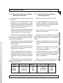
2.1.1. Responsabilità
2.1.1. Limitations of liability
Il costruttore declina ogni responsabilità
da eventuali danni agli apparati ed alle persone causati a seguito di errati collegamenti
o di manovre non espressamente descritte.
The constructor shall not be liable for
consequential damages to the equipment or
person based on wrong connections or operations non specifically set forth.
Installazione Installation 2 - 3
INSTALLAZIONE - INSTALLATION
2
UPS 60 -120 kVA ATLAS Manuale tecnicoDT0342 ediz. 00 - Technical handbook DT0342 Issue 00
2
2.1.2. Ricevimento del materiale
2.1.2. Material admittance
All'atto della ricezione verificare che il materiale non abbia subito danneggiamenti durante il
trasporto; ispezionare perciò accuratamente i
contenitori e, dopo la rimozione dell'imballo, il
perfetto stato del contenuto.
When receiving the material check for damages that it might have suffered during transportation. Therefore, properly inspect the packing
case and after having removed the packing
material check that the contents are in perfect
condition.
Afterwards ascertain that the material supplied is as that reported on the freight bill.
Successivamente assicurarsi che il materiale fornito corrisponda a quanto indicato sulla
bolla d'accompagnamento.
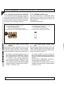
2.1.3. Identification
INSTALLAZIONE - INSTALLATION
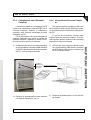
2.1.3. Identificazione
I gruppi forniti sono identificati tramite una targhetta adesiva applicata sul pannello posteriore dell'UPS, sulla quale
sono riportati modello e potenza dell'UPS.
Di seguito viene descritta
la procedura a cui attenersi per
disimballare correttamente i
contenitori utilizzati per la spedizione dei gruppi.
The equipment supplied is provided with an
adhesive identification label
placed on the UPS rear panel
reporting type of UPS model
and power.
Mod.
KVA
In
Imax
Out
CE
Targhetta dell'UPS - UPS Label
The cases utilized to transport
the equipment must be unpacked as specified by the procedure stated below.
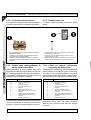
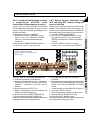
2.1.4. Rimozione dell'imballo
2.1.4. Packing material removal
Durante questa operazione rispettare le indicazioni (FRAGILE, ALTO) riportate sul contenitore al fine di evitare danneggiamenti dell'UPS.
During this operation observe the indications
(FRAGILE, UP) printed on the case to avoid
damaging the UPS.
Per la rimozione dell'imballo procedere secondo le istruzioni della seguente procedura
(fare riferimento alla fig. 2.1):
To remove the packing material proceed in
the following manner (see Fig. 2.1):
-
-
Attenendosi a quanto riportato sul contenitore esterno (ALTO, BASSO), posizionare
correttamente l'apparato sul pavimento.
-
place the equipment on the floor as instructed on the outer case (UP, DOWN).
Rimuovere il coperchio e i laterali della gabbia di legno
-
Remove the cover and the side parts of the
wooden crate.
2 - 4 - Installazione Installation
UPS 60 -120 kVA ATLAS Manuale tecnicoDT0342 ediz. 00 - Technical handbook DT0342 Issue 00
a) posizionare l'UPS correttamente sul
pavimento, rispettando il verso ALTO/
BASSO
place it properly on the floor observing the
UP/DOWN indications
b) Rimuovere la struttura dell'imballo
facendo attenzione.
Remuve the board,carefully.
c) eliminare il foglio di protezione in
polietilene.
remove the polyethylene.
d) con un muletto appoggiare l'UPS a terra
use a forklift truck to place UPS on the floor
Fig. 2.1 - Rimozione dell'imballo dell'UPS
Packing removal from UPS
Installazione Installation 2 - 5
INSTALLAZIONE - INSTALLATION
2
UPS 60 -120 kVA ATLAS Manuale tecnicoDT0342 ediz. 00 - Technical handbook DT0342 Issue 00
INSTALLAZIONE - INSTALLATION
2
-
Togliere l'involucro di cellophane di protezione.
-
Remove the cellophane wrapping utilized as
protection packing.
-
Infilare le forche di un muletto sotto l'UPS e,
dopo averlo sollevato di qualche centimetro,
indietreggiare e appoggiarlo sul pavimento.
L'UPS è dotato di ruote con le quali può
essere spostato senza fatica.
-
Slide the forks of the lift truck under the UPS
and after having lifted it a few centimeters
from the floor, back up and lay it down. UPS
is provided with wheels to easily move it
around.
-
Si consiglia di conservare tutto il materiale
d'imballaggio; potrebbe essere utilizzato
qualora fosse necessario il reimballaggio
dell'apparecchiatura (es.: restituzione, invio
a centri di manutenzione, traslochi).
-
Do not throw away the packing material in
that it might be used again to repack the
equipment if having to send it back or to
send it to maintenance centers or for removal purposes.
-
Verificare che il gruppo non abbia subito
danneggiamenti; in caso contrario contattare immediatamente il rivenditore.
-
Check that the equipment has not been
damaged. If otherwise immediately contact
the Sales Representative.
2.1.5. Immagazzinamento
2.1.5. Storing
Nel caso in cui l'apparato non venga immediatamente installato occorre immagazzinarlo in
un ambiente in grado di proteggerlo sia dall'eccessiva umidità sia da fonti di elevato calore (da
+5 a +40 °C, umidità minore del 95 % non
condensante).
Should the equipment not be installed immediately it must be stored in a room so as to
protect it against excessive humidity and against
very high heat sources i.e., +5° to +40°C, and
humidity not lower than 95% and moistureless.
Nel caso sia fornito il quadro batteria,
ssicurarsi, inoltre, che tra l'ultima ricarica
delle batterie e la successiva non trascorrano più di 6 mesi. Trascorso tale periodo procedere all'allacciamento provvisorio dell'UPS alla
rete e attivarlo per il tempo necessario ad effettuare la ricarica delle batterie.
Vedere § 2.5 - Allacciamento provvisorio per la
ricarica delle batterie.
If battery cubicle is supplied, make sure that
not more than 6 months pass from the time
the battery had last been recharged. After
such period temporarily connect the UPS to
mains and activate it for the time required to
recharge the batteries.
Refer to para. 2.5 – Temporary connection to
enable battery recharge.
2 - 6 - Installazione Installation
UPS 60 -120 kVA ATLAS Manuale tecnicoDT0342 ediz. 00 - Technical handbook DT0342 Issue 00
2
2.1.6. Siting it in the operative position
L'UPS è dotato di ruote che permettono di
posizionarlo facilmente nel luogo più adatto.
La posizione scelta deve garantire:
- comodità di allacciamento;
- spazi sufficienti per un'agevole operatività
sull'UPS , anche in previsione degli interventi
di manutenzione periodica e straordinaria.
- ricambio di aria sufficiente a smaltire il calore prodotto dall'UPS;
- protezione dagli agenti atmosferici;
- protezione dall'eccessiva umidità o da fonti
di elevato calore;
- protezione da polvere;
- rispetto delle norme antincendio vigenti.
- ambiente operativo a temperatura compresa tra +20 e +25 °C: in questo campo di
temperature si ha la massima efficienza
delle batterie.
The UPS is fitted with wheels so as to easily
move it to the right place. The place chosen must
guarantee:
- easy connection;
- enough space to easily work on UPS , considering also troubleshooting and corrective
maintenance operations;
- interchange of air sufficient enough to dispel
heat produced by UPS;
- protection against atmospheric agents;
- protection against excessive humidity and
very high heat sources;
- protection against dust;
- compliance with the current fire prevention
norms.
- operative environment temperature within
+20° C and +25° C. The batteries are at
maximum efficiency in this temperature
range.
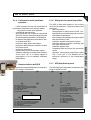
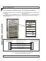
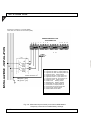
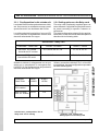
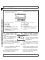
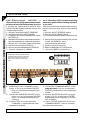
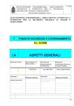
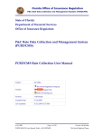
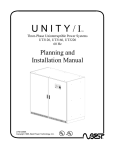
2.1.7. Quadro elettrico dell'UPS
2.1.7. UPS distribution panel
Nel seguito viene data la disposizione degli interruttori e relative connessioni.
The following figure illustrates the switches and
plugs arranged on UPS.
(1)
(2)
(a)
(b)
Connessioni esterne
(a) = Ingresso rete principale U1-V1-W1-N1
(b) = Ingresso linea di riserva U3-V3-W3-N3
(c) = Uscita U2-V2-W2-N2
(d) = Barra GND
(e) = Morsetti armadio batterie
(3)
(c)
(6)
(5)
(d)
External connections
(a) = Input mains terminal blocks U1-V1-W1-N1
(b) = Reserve line terminal blocks U3-V3-W3-N3
(c) = Output terminal blocks U2-V2-W2-N2
(d) = GND busbar
(d) = Ext. Battery terminal blocks
(4)
(e)
Legenda dispositivi
(1) = Interruttore Ingresso rete
(2) = Interruttore Ingresso linea si riserva
(3) = Interruttore di By-pass mauale
(4) = Interruttore d'uscita (al carico)
(5) = Barra gnd
(6) = Sezionatore batterie con fusibile
Devices description
(1) = Input mains MCB
(2) = ReserveInput MCB
(3) = Manual By-pass MCB
(4) = UPS Output MCB (to load)
(5) = GND bar
(6) = Battery fuses
Installazione Installation 2 - 7
INSTALLAZIONE - INSTALLATION
2.1.6. Collocazione nella posizione
operativa
UPS 60 -120 kVA ATLAS Manuale tecnicoDT0342 ediz. 00 - Technical handbook DT0342 Issue 00
2.2. ALLACCIAMENTO DELL'UPS
ALLA RETE
2.2. UPS CONNECTION TO THE
MAINS
Per garantire il corretto funzionamento
dell'UPS e dei suoi eventuali equipaggiamenti
opzionali è necessario approntare opportunamente la rete elettrica sia a monte che a valle
dell'apparecchiatura, dotandola di appositi
dispositivi di protezione.
I collegamenti da realizzare sono
schematizzati in Fig. 2.2.
To guarantee that the UPS and relative
optional equipment operate properly a mains
point must be provided both at the input and
output of the equipment which must also be
provided with the specific protection devices.
The wiring connections to be executed are
shown in Fig. 2.2
LE OPERAZIONI DESCRITTE NEI SUCCESSIVI PARAGRAFI DEVONO ESSERE ESEGUITE DA ELETTRICISTI AUTORIZZATI O
DA PERSONALE TECNICO QUALIFICATO.
THE OPERATIONS DESCRIBED IN THE FOLLOWING PARAGRAPHS MUST BE CARRIED OUT BY AUTHORIZED ELECTRICIANS
OR BY TECHNICAL PERSONNEL.
rete 380÷415Vca/50 Hz 3fase+N+PE (GND)
mains 380÷415 Vac/50 Hz 3ph+N+PE (GND)
Interruttore di By-pass UPS (normalmente aperto)
UPS By-pass switch (normally open)
Interruttore magnetotermico (1) “Curva C”
Magnetothermic switch (1) “Curve C”
Interruttore magnetotermico “Curva C”
Magnetothermic switch “Curve C”
alle utenze - To users
INSTALLAZIONE - INSTALLATION
2
UPS
(1)
= Interruttore magnetotermico quadripolare differenziale per correnti alternate, pulsanti con componente
continua, contraddistinto dalla presenza del simbolo
. Il valore minimo di intervento deve essere
500 mA.
a.c. four-pole safety magnetothermic switch, push-button with dc component,
distinguished by symbol
. The minimum time to intervene must be 500 mA.
Fig. 2.2 - Schema di principio per l'installazione dell'UPS
UPS installation schematic
2 - 8 - Installazione Installation
UPS 60 -120 kVA ATLAS Manuale tecnicoDT0342 ediz. 00 - Technical handbook DT0342 Issue 00
2.2.1. Preparazione della rete d'alimentazione primaria trifase
2.2.1. Setting up the three-phase primary supply mains
Prima di procedere al collegamento dell'UPS
è necessario:
Before connecting the UPS check that:
-
verificare che i valori della tensione e della
frequenza di rete corrispondano a quelli
indicati sull'etichetta adesiva presente sulla
parte posteriore dell'UPS (tensione di ingresso, frequenza di lavoro);
-
the mains voltage and frequency values are
as those indicated on the adhesive label
attached on the rear plane of the UPS (input
voltage, working frequency);
-
verificare che la messa a terra dell'impianto
sia rigorosamente conforme a quanto previsto dalle norme IEC o del luogo vigenti.
-
plant grounding fully complies either with
IEC norms or local laws.
Successivamente, procedere all'installazione, a monte e a valle dell'UPS, di interruttori
magnetotermici quadripolari (vedi Fig. 2.2) aventi le seguenti caratteristiche:
Afterwards, start installing the four-pole
magnetothermic switches both at the input and
output of the UPS (see Fig. 2.2). The switches
feature:
-
portata uguale o maggiore di quella indicata
sull'etichetta presente sulla parte posteriore
dell'UPS (KVA);
-
capacity equal or greater than that reported
on the label situated on the UPS rear plane
(KVA);
-
caratteristiche conformi a quanto previsto
dalle norme CEI o del luogo vigenti per i
magnetotermici “Curva C”.
-
characteristics compliant either with IEC
norms or local laws for “Curve C”
magnetothermic switches.
-
I cavi di collegamento devono avere una
lunghezza tale da permettere l'avanzamen
to dell'UPS di almeno 80cm per l'accessibi
lità laterale e posteriore in caso di manuten
zione.
-
Connecing cables must have a suitable
lenght to allow the cubicle to advance at least
80cm, for lateral and back accessibility in
case of mantainance.
I collegamenti devono essere realizzati utilizzando cavi flessibili con sezione come indicata nella seguente tabella:
P(KVA)
60kVA
80kVA
100kVA
120KVA
Ø A.C.(mm2)
5 x 25 mm2
5 x 35 mm2
5 x 50 mm2
5 x 70 mm2
Wiring must be flexible cable with the
section as suggested in the following table:
MCB (A)
100A
120A
150A
180A
Ø D.C. (mm2)
2x70 mm2
2x 2x50 mm2
2x 2x70 mm2
2x 2x70 mm2
I D.C. (A)
160A
220A
270A
320A
Installazione Installation 2 - 9
INSTALLAZIONE - INSTALLATION
2
UPS 60 -120 kVA ATLAS Manuale tecnicoDT0342 ediz. 00 - Technical handbook DT0342 Issue 00
2
2.2.2. Collegamenti alla morsettiera
INSTALLAZIONE - INSTALLATION
LE OPERAZIONI DESCRITTE IN QUESTO
PARAGRAFO DEVONO ESSERE ESEGUITE
DA ELETTRICISTI AUTORIZZATI O DA PER- 2.2.2. Tagblock wiring
SONALE TECNICO QUALIFICATO.
Per tutti i collegamenti utilizzare cavi con sezione come indicata nella tabella a pag. 2-9.
Per la sicurezza del personale addetto
all'installazione assicurarsi che le operazioni
di collegamento vengano effettuate nelle seguenti condizioni:
- assenza della tensione primaria di rete;
- utenze disattivate;
- UPS totalmente disattivato.
a)
b)
c)
1)
2)
THE OPERATIONS DESCRIBED IN THE
PARAGRAPHS THAT FOLLOW MUST BE
CARRIED OUT BY AUTHORIZED ELECTRICIANS OR BY TECHNICAL PERSONNEL.
Use section cables as described in page 2-9.
As far as the installation personnel’s
safety is concerned, make sure that the wiring
operations are carried out under the following
conditions:
Per disattivare totalmente l'UPS:
- primary mains voltage cut off;
aprire gli interruttori di ingresso rete (1), di - users cut-off;
linea di riserva (2), di uscita (4);
- UPS fully de-activated.
aprire il sezionatore batterie (5);
aprire l'interruttore di BY-PASS (3)
To fully deactivate the UPS:
a) open the main power switch (1),the reserve
Aprire la porta e rimuovere il pannello di
line switch (2), the output switch (4) by setprotezione inferiore.
ting the lever to the down position
Collegare al collettore di terra il cavo di b) open the battery switch (5) by setting the
terra proveniente dal quadro di distribulever to the down position;
zione principale.
(1)
(2)
(3)
(4)
(5)
c) open the BY-PASS switch (3) by setting the
lever it to the down position.
1) Open the door and remove the lower
protection panel
2) Connect the ground lead, incoming from
the main distribution panel, to the GND
busbar of the cubicle.
2 - 10 - Installazione Installation
UPS 60 -120 kVA ATLAS Manuale tecnicoDT0342 ediz. 00 - Technical handbook DT0342 Issue 00
2
La sezione raccomandata
dei fili è descritta nella tabella a pag.2-9.
Le norme di riferimento per
la dimensione dei cavi
sono: VDE 0100 parte 3 e
UNEL 35024170
Use section cables as
described in the table of
pag.2-9.The reference
norms adopted for the
dimensions of the
cables are: VDE 0100
part 3 and
UNEL 35024170
4)Connect mains cables to isolator
I1terminal blocks , as indicated on figure.
5) Connect load cables to isolator I4
terminal blocks.
6) Connect reserve mains cables to
isolator I3 terminal bloks
7)Connect cables from battery cubicle to
isolating fuses terminals
MORSETTIERA DELL'UPS
UPS TAGBLOCK
1
2
3
4
5
6
7
8
(U1) (V1) (W1) (N1) (U3) (V3) (W3) (N3)
11 12 13
14
(U2) (V2) (W2) (N2)
9
(+)
ingresso rete
Mains input
massa
Ground
10
(-)
uscita UPS
UPS output
ingresso linea di riserva
reserve input
(15)
ingresso batteria
battery input
filo di terra verso le utenze
Ground lead towards users
1
2
3
4
5
6
7
8
3) Connect ground for utilities to the
UPS GND busbar .
= Ingresso rete fase U1 Output phase U2
= Ingresso rete fase V1 Output phase V2
= Ingresso rete fase W1Output phase W2
= Ingresso neutro Output neutral
= Ingresso riserva U1 Input reserve U1
= Ingresso riserva V1 Input reserve V1
= Ingresso riserva W1 Input reserve W1
= Ingresso neutro Output neutral
9 = Positivo batt.
Battery positive
10 = Negativo batt. Battery negative
11 = Uscita fase U2 Output phase U2
12 = Uscita fase V2 Output phase V2
13 = Uscita fase W2 Output phase W2
14 = Uscita neutro Output neutral
15 = Massa GND Ground GND
collegare a questo
collettore il filo di terra
proveniente dalla rete di
alimentazione in ingresso
all'UPS
Onto this terminal connect
the ground lead incoming
from the UPS input mains
power supply
Fig. 2.3 - Collegamenti alla morsettiera dell'UPS
Wiring on the UPS tagblock
Installazione Installation 2 - 11
INSTALLAZIONE - INSTALLATION
3) Collegare il cavo di terra per l'alimentazione delle utenze alla barra di terra
dell'UPS.
4) Collegare i cavi della rete di ingresso ai
terminali del sezionatore I1, come indicato nella figura.
5) Collegare i cavi di alimentazione per le
utenze ai terminali del sezionatore I4.
6) Collegare i cavi della rete di riserva ai
terminali del sezionatore I3.
7) Collegare i cavi dell'armadio batterie ai
terminali dei fusibili sezionabili
UPS 60 -120 kVA ATLAS Manuale tecnicoDT0342 ediz. 00 - Technical handbook DT0342 Issue 00
INSTALLAZIONE - INSTALLATION
2
2.2.3. Allacciamento delle utenze
2.2.3. User connection
E' consigliato collegare a valle dell'UPS un apposito interruttore magnetotermico quadripolare
“Curva C” (vedere fig. 2.2 e fig. 2.4).
Its suggested to connect a four-pole “Curve C”
magnetothermic switch at the output of the UPS
(see Fig. 2.2 and Fig. 2.4).
LE OPERAZIONI DESCRITTE IN QUESTO
PARAGRAFO DEVONO ESSERE ESEGUITE
DA ELETTRICISTI AUTORIZZATI O DA PERSONALE TECNICO QUALIFICATO.
THE OPERATIONS DESCRIBED IN THE
PARAGRAPHS THAT FOLLOW MUST BE
CARRIED OUT BY AUTHORIZED ELECTRICIANS OR BY TECHNICAL PERSONNEL.
I collegamenti devono essere effettuati nelle
seguenti condizioni:
- assenza della tensione primaria di rete;
- utenze disattivate;
- UPS totalmente disattivato.
The wiring operations must be carried out under
the following conditions:
- primary mains voltage cut off;
- users cut-off;
- UPS fully de-activated.
interruttore magnetotermico
quadripolare “Curva C”
four-pole “Curve C”
magnetothermic switch
QUADRO DI DISTRIBUZIONE ALLE UTENZE
LOAD DISTRIBUTION PANEL
magnetotermico
differenziale 1
safety
magnetothermic 1
presa
utenza 1
User
socket 1
La barra presente sotto gli interruttori consente l'ancoraggio del cavo
all'UPS stesso mediante l'impiego
di fascette fermacavi.
magnetotermico
differenziale 2
safety
magnetothermic 2
presa
utenza 2
User
socket 2
magnetotermico
differenziale ...n
safety
magnetothermic ..n
presa
utenza n
User
socket n
The bar near the switch blocks can be
used to fasten the cable to the UPS
through cable clamps.
UTENZA 1 - USER 1
UTENZA 2 - USER 2
Fig. 2.4 - Quadro di distribuzione alle utenze
Load distribution Panel
2 - 12 - Installazione Installation
UTENZA-n / USER-n
UPS 60 -120 kVA ATLAS Manuale tecnicoDT0342 ediz. 00 - Technical handbook DT0342 Issue 00
2
Collegare il cavo di uscita dell'UPS ai
morsetti “15” (terra), “11-12-13” (fase) e
“14” (neutro) dell'interruttore magnetotermico “Curva C” del “Quadro di Distribuzione alle utenze”.
-
Connect the UPS output cable to terminals “15” (ground), “11-12-13” (phase)
and “14” (neutral) of the “Curve C”
magnetothermic switch on the “User Distribution Panel”.
Le uscite dell'interruttore “Curva C” devono essere collegate in parallelo alle prese d'utenza; si
consiglia di realizzare questo collegamento mediante l'utilizzo di ulteriori interruttori
magnetotermici differenziali, uno per ciascuna
presa: i magnetotermici consentiranno, se necessario, di isolare le singole utenze.
Outputs of the “Curve C” switch must be parallelconnected to the user sockets; it is suggested to
set up this link using other safety magnetothermic
switches, one per socket: the magnetothermic
switches will, if necessary, isolate each single
user.
Le caratteristiche degli interruttori
magnetotermici da inserire a monte delle utenze,
così come la sezione dei cavi, dipendono dai
carichi previsti sulle varie prese.
The characteristics of the magnetothermic
switches, to insert at the user input, and the
cable sections are based on the loads applied to
the various sockets.
Terminate le operazioni di collegamento
montare nuovamente il pannello di protezione
alla morsettiera di connessione dell'UPS.
At the end of every connection, assembly again
the protection panel on the UPS tagblock.
Quindi collocare l'UPS nella posizione ideale per il servizio.
Place UPS into the position considered most
fitting for the use .
Installazione Installation 2 - 13
INSTALLAZIONE - INSTALLATION
-
UPS 60 -120 kVA ATLAS Manuale tecnicoDT0342 ediz. 00 - Technical handbook DT0342 Issue 00
INSTALLAZIONE - INSTALLATION
2
2.3. ALLACCIAMENTO A DISPOSITIVI ESTERNI
2.3. EXTERNAL DEVICES CONNECTION
Sul pannello posteriore dell'UPS è disponibile una scheda Relè per collegare l'UPS a un
pulsante di spegnimento d'emergenza dell'UPS
(E.P.O.= Emergency Power Off).
Tramite un connettore DB9, la scheda consente
inoltre di collegare l'UPS a un Personal Computer e mediante la morsettiera posta sulla stessa
di collegare l'UPS a un pannello remoto per le
segnalazioni dello stato.
A Relay card is situated on UPS rear panel.
Through this card UPS is connected to a
pushbutton whose function is of forcing UPS
OFF should an emergency condition arise (E.P.O.
= Emergency Power Off).
Through plug DB9 the card can establish connection with UPS to a Personal Computer.
Throught tag-block on it is possible to connect
UPS to a remote panel for UPS status indications.
2.3.1. Collegamento del pulsante per lo
spegnimento forzato (E.P.O.)
2.3.1. Emergency Power Off (E.P.O.)
push-button connection
1) Munirsi di un cavo bipolare (sezione dei
conduttori 0,6 mm2) di lunghezza opportuna, non superiore a 100 m.
2) Intestare un'estremo del cavo ai morsetti
N.C. di un pulsante antincendio (fig. 2.5).
3) Collegare gli estremi opposti dei cavi alla
scdeda Relè (fig. 2.5).
1) Get a suitably long (not more than 100 m.)
two-pole cable (0.6sq.mm conductor section)
2) Terminate one end of the cable to the N.C.
pins of a fire preventing button (Fig. 2.5).
3) connect the other end of the cable to
Relay card (Fig. 2.5).
NOTA: è possibile dotare l'UPS di un'altra scheda Relè (opzionale)
e collegarlo così sia al pannello remoto che al PC. Non è possibile
collegare a tale scheda un secondo pulsante EPO. Per collegare
all'UPS più pulsanti EPO è necessario porli in serie tra loro e poi
collegare la serie a uno dei CN3 disponibili.
NOTE: Another Relè card (optional) can be mounted on UPS
hence connecting it both to the remote panel and to the PC. The
card cannot be fitted with an additional EPO button. To connect
several EPO buttons to UPS first connect them in series and then
connect the lot to one of the CN3s available.
○ ○ ○
○ ○ ○
○ ○ ○
○ ○ ○
○
pulsante E.P.O.
E.P.O. pushbutton
scheda Relè
Relè card
N.C.= Normalmente Chiuso
Normally Closed
Fig. 2.5 - Collegamento del pulsante E.P.O. - E.P.O. connection
2 - 14 - Installazione Installation
UPS 60 -120 kVA ATLAS Manuale tecnicoDT0342 ediz. 00 - Technical handbook DT0342 Issue 00
2.3.2. Collegamento con il Personal
Computer
2.3.2. Connection to Personal Computer
L'interfaccia segnali che equipaggia l'UPS
consente di monitorare lo stato dell'UPS con il
Personal Computer. Qualora si verificassero
anomalie, esse verranno visualizzate in modo
dettagliato sul PC.
Per la realizzazione di questo collegament
utilizzare l'apposito cavo fornito a corredo del
software Generex. Il software e il relativo corredo sono forniti in opzione su richiesta.
The signals interface equipping UPS monitors the state of UPS with the Personal Computer. Any failures present will be fully displayed on
the PC.
To set up this connection use the cable
supplied with the Generex software. The software together with the relative kit are optionally
supplied on Customer demand.
1) Collegare l'estremo con connettore maschio
al corrispondente connettore DB9 femmina
sull'UPS e l'altro estremo ad una porta seriale
del PC, come di seguito illustrato.
1) Connect the male connector tipped end to
the corresponding DB9 female connector
on UPS and the other end to a serial port on
the PC as shown below.
connettore
DB9 femmina alla porta seriale del PC
DB9 female To the PC serial port
connector
2) Eseguire le predisposizioni come descritto
nel capitolo Attivazione, § 4.2.4.
2) Preset as specified at para. 4.2.4 in the Setup chapter.
Installazione Installation 2 - 15
INSTALLAZIONE - INSTALLATION
2
UPS 60 -120 kVA ATLAS Manuale tecnicoDT0342 ediz. 00 - Technical handbook DT0342 Issue 00
2
2.3.3. Collegamento al Pannello remoto 2.3.3. Remote Panel connection
Il Pannello segnalazioni remoto è corredato di
alimentatore.
Costruire un cavo di collegamento di lunghezza idonea, non superiore a 100 m, come da
schema di figura 2.6.
The remote signalling panel is provided with a
power supply unit.
Proceed to assemble a connecting cable up but
not longer than 100m as shown in Figure 2.6.
INSTALLAZIONE - INSTALLATION
Morsettiera M1
M1 Tag-block
LOW BATTERY
ON BYPASS
ALARM SILENCE
POWER ON
Morsettiera (lato UPS)
Tagblock (UPS side)
sezione 0,6 mm2 L. max. = 100 m
0.6 sq.mm. section max. L. = 100 m.
Tagblock (panel side)
Batteria scarica - Low battery
Comune - Common
1
2
Rete 230 V presente - 230V mains ON
4
By pass inserito - By pass ON
9
UPS ON - UPS ON
12
Morsettiera (lato pannello)
1
5
4
3
2
Fig. 2.6 - Schema del cavo di collegamento al Pannello remoto
Drawing showing Remote Panel wiring cable
2 - 16 - Installazione Installation
UPS 60 -120 kVA ATLAS Manuale tecnicoDT0342 ediz. 00 - Technical handbook DT0342 Issue 00
2
2.4. SCHEDA RELÈ (OPZIONALE)
2.4. RELAY CARD (OPTIONAL)
A richiesta, viene fornita una scheda Relè che
può essere aggiunta alla scheda Relè standard(1).
A Relay card is supplied upon customer demand. This card can be added to the Relè one(1).
1) Eseguire i collegamenti come nello schema
di figura 2.7.
2) Eseguire la predisposizione dei ponticelli
come descritto nel capitolo Attivazione.
1) Proceed to wire-connect as shown on the
diagram of Fig. 2.7.
2) Strap preset as reported in the Set up chapter
: non è possibile collegare alla scheda Relè un secondo pulsante
EPO. Per collegare al UPS più pulsanti EPO è necessario porli in
serie tra loro e poi collegare la serie a uno dei CN3 disponibili.
: The Relay card cannot be fitted with an additional EPO
button. To connect several EPO buttons to UPS first connect
them in series and then connect the lot to one of the CN3s
available.
morsettiera di collegamento all'UPS
UPS connection tagblock
morsetti per il collegamento
E.P.O. (vedere fig. 2.5)
E.P.O. wiring terminals (see
Fig. 2.5)
connettore DB9 per il
collegamento al Personal
Computer (vedere § 2.3.2)
DB9 plug for Personal
Computer connection (see
para. 2.3.2)
N.O.
COM.
N.C.
N.O.
COM.
N.C.
N.O.
COM.
N.C.
N.O.
COM.
N.C.
morsettiera con morsetti liberi da
tensione, a disposizione dell'Utente
(collegamento al Pannello remoto
§ 2.3.3.)
Tagblock with cold contacts free
for the User (Remote Panel
connection see para. 2.3.3)
UPS IN FUNZIONE
UPS RUNNING
BY- PASS INSERITO
BY-PASS ON
PRESENZA RETE
MAINS PRESENCE
BATTERIA SCARICA
BATTERY FLAT
Legenda - Legend:
N.O. = Normalmente aperto - Normally open
COM. = Comune - Common
N.C. = Normalmente Chiuso - Normally Closed
Fig. 2.7 - Schema dei collegamenti della scheda interfaccia segnali con relè
Signals interface with relay card wiring diagram
Installazione Installation 2 - 17
INSTALLAZIONE - INSTALLATION
(1)
(1)
UPS 60 -120 kVA ATLAS Manuale tecnicoDT0342 ediz. 00 - Technical handbook DT0342 Issue 00
INSTALLAZIONE - INSTALLATION
2
2.5. ALLACCIAMENTO PROVVISORIO PER LA RICARICA
DELLE BATTERIE
2.5. TEMPORARY CONNECTION
TO ENABLE BATTERY RECHARGE
LE OPERAZIONI DESCRITTE IN QUESTO
PARAGRAFO DEVONO ESSERE ESEGUITE
DA ELETTRICISTI AUTORIZZATI O DA PERSONALE TECNICO QUALIFICATO.
THE OPERATIONS DESCRIBED IN THE
PARAGRAPHS THAT FOLLOW MUST BE
CARRIED OUT BY AUTHORIZED ELECTRICIANS OR BY TECHNICAL PERSONNEL.
2.5.1. Verifiche e predisposizioni
2.5.1. Tests and setting options
Before wire-connecting the UPS, check:
Prima di procedere al collegamento dell'UPS
verificare:
1) i valori della tensione e della frequenza di
rete: essi dovranno corrispondere a quelli
indicati sull'etichetta adesiva presente sulla
parte posteriore dell'UPS (tensione di ingresso, frequenza di lavoro);
1) the mains voltage and frequency values:
these must correspond to those
indicated on the adhesive label attached on
the rear plane of the UPS (input voltage,
working frequency);
2) la portata dell'interruttore magnetotermico:
deve essere uguale o maggiore di quella
indicata sull'etichetta adesiva presente sulla parte posteriore dell'UPS (KVA);
2) magnetothermic switch capacity: must be
equal or greater than that reported on the
label situated on the UPS rear plane (KVA);
3) la messa a terra dell'impianto: deve essere
conforme a quanto previsto dalle norme IEC
o dalle norme localmente vigenti.
3) plant grounding: must fully comply either
with IEC norms or local laws.
Per la sicurezza del personale addetto
all'installazione assicurarsi che le operazioni di
collegamento vengano effettuate nelle seguenti
condizioni:
As far as the installation personnel’s
safety is concerned, make sure that the wiring
operations are carried out under the following
conditions:
-
assenza della tensione primaria di rete;
-
primary mains voltage cut off;
-
UPS totalmente disattivato.
-
UPS fully de-activated.
Per disattivare totalmente l'UPS:
a) aprire, leva in posizione orizzontale (OFF),
gli interruttori di ingresso rete (1), di linea di
riserva (2), di uscita (4);
2 - 18 - Installazione Installation
To fully deactivate the UPS:
a) open the main power switch (1),the reserve
line switch (2), the output switch (4) by setting the lever to the horizontal position
UPS 60 -120 kVA ATLAS Manuale tecnicoDT0342 ediz. 00 - Technical handbook DT0342 Issue 00
2
b) aprire, posizione orizzontale(OFF),il
sezionatore batterie (5);
c) aprire,posizione orizzontale
(OFF),l'interruttore di BY-PASS (3);
(1)
(2)
b) open the battery switch (5) by setting the
lever to the down position;
c) open the BY-PASS switch (3) by setting the
lever it to the down position.
(3)
(4)
2.5.2. Esecuzione dei collegamenti
2.5.2. Wiring
1) Svitare completamente le quattro viti del
pannello di protezione della morsettiera
dell'UPS.
1) Fully unscrew the four screws from the protection panel situated on the UPS tagblock.
2) Collegare alla barra di terra “15” dell'UPS il
cavo di terra (fig. 2.8).
Per il collegamento della messa a terra
utilizzare un cavo con sezione di almeno 6
mm2.
2) Connect the ground lead to the “PE” bar of
the UPS (Fig. 2.8).
To ground connect use a 6 sq.mm. section
cable.
3) Collegare il cavo della tensione di rete (fig.
2.8) ai seguenti morsetti dell'UPS:
1 = fase U1
2 = fase V1
3 = fase W1
4 = neutro N1
3) Connect the mains voltage lead (see Fig.
2.8) to the following UPS terminals:
1 = phase U1
2 = phase V1
3 = phase W1
4 = neutral N1
Per il collegamento della tensione di rete
utilizzare conduttori con sezione di almeno
6 mm2.
With regard to mains voltage connection use a 6
sq.mm. section cable.
Ultimati i collegamenti avviare la carica delle
batterie attenendosi a quanto descritto nel capitolo USO E MANUTENZIONE.
After having completed the wiring connections charge the batteries as instructed in the
USER MANUAL chapter.
Installazione Installation 2 - 19
INSTALLAZIONE - INSTALLATION
(5)
UPS 60 -120 kVA ATLAS Manuale tecnicoDT0342 ediz. 00 - Technical handbook DT0342 Issue 00
2
rete 380÷415 Vca/50 Hz - 3F+N+PE (GND)
mains 380÷415 Vac/50 Hz 3PH+N+PE (GND)
MORSETTIERA DELL'UPS
UPS TAGBLOCK
INSTALLAZIONE - INSTALLATION
1 2
3
16 17 18
4
5
6
7
8
11 12 13 14
9
10
15
(A)
(B)
U1
V1
W1
N1
Sezione-Section:6 mm2
PE (terra - gnd)
PE (ground – gnd)
1 = Ingresso rete fase U1 Output phase U2
2 = Ingresso rete fase V1 Output phase V2
3 = Ingresso rete fase W1Output phase W2
4 = Ingresso neutro Output neutral
5 = Ingresso riserva U1 Input reserve U1
6 = Ingresso riserva V1 Input reserve V1
7 = Ingresso riserva W1 Input reserve W1
8 = Ingresso neutro Output neutral
9 = Positivo batt.
Battery positive
10 = Negativo batt. Battery negative
11 = Uscita fase U2 Output phase U2
12 = Uscita fase V2 Output phase V2
13 = Uscita fase W2 Output phase W2
14 = Uscita neutro Output neutral
15 = Massa GND Ground GND
Fig. 2.8 - Allacciamento provvisorio per la ricarica delle batterie
Temporary connection to enable battery recharge
2 - 20 - Installazione Installation
UPS 60 -120 kVA ATLAS
Manuale tecnicoDT0342 ediz. 00 - Technical handbook DT0342 Issue 00
3 - ATTIVAZIONE
3 - SETUP
Indice
Table of contents
3.1. Prima accensione e verifiche ....... 2
3.1. Initial turn-on and checks ............. 2
3.1.1. Istruzioni per la prima accensione
dell’UPS ................................................2
3.1.2. Verifica dello stato dell'UPS sull
pannello frontale e delle
segnalazioni .......................................... 3
3.1.3. Prova di inserimento del carico ............. 3
3.1.4. Prova di intervento dell’UPS .................. 4
3.1.5. Prova dello stato di carica della
batteria ..................................................4
3.1.6. Prova di commutazione su linea di
riserva (By-pass automatico) ................5
3.1.7. Verifica del funzionamento del
By-pass manuale ..................................5
3.1.1. UPS Initial turn-on
instructions ...........................................2
3.1.2. Check on the UPS status
of the front panel and
signalling ...............................................3
3.1.3. Load insertion test .................................3
3.1.4. UPS intervention test ............................4
3.1.5. Test on the battery charge
condition ................................................4
3.1.6. Test on switching over to the reserve line
(automatic by-pass) .............................. 5
3.1.7. Manual By-pass
operation check ....................................5
3.2. Predisposizioni disp.opzionali .... 6
3.2. Setting options .............................. 6
3.2.1. Predisposizioni sulla scheda relè .........7
3.2.2. Predisposizioni per la comunicazione
con il PC ...............................................8
3.2.1 Setting options on the Relay card .........7
3.2.2. PC Interaction setting ........................... 8
3.3. Attivazione dei dispositivi
periferici ......................................... 9
3.3. Pheripheral device set-up ............. 9
3.3.1. Verifica del circuito di spegnimento
forzato in emergenza (E.P.O.) ..............9
3.3.2. Prova del pannello remoto .................. 10
3.3.3. Verifica delle telesegnalazioni
in uscita dalla scheda Relè ................. 10
3.3.1. Check of the Emergency Power Off
circuit (E.P.O.)....................................... 9
3.3.2. Remote panel test ............................... 10
3.3.3. Check on remote indications outputting
the Relay Card .................................... 10
Rev
Descrizione
Data
Controllato
Realizzato
U.T. PTX
Data
Tipo di doc.
Pagine n°
Pag. totali
10/10/2003
Approvato
Cod.
DT0342-E00
Attivazione Setup 3 - 1
ATTIVAZIONE - SETUP
3
UPS 60 -120 kVA ATLAS
Manuale tecnicoDT0342 ediz. 00 - Technical handbook DT0342 Issue 00
3
3.1. PRIMA ACCENSIONE E
VERIFICHE
3.1. INITIAL TURN-ON AND
CHECKS
3.1.1. Istruzioni per la prima accensione
dell’UPS
3.1.1. UPS Initial turn-on instructions
Gli interruttori d’accensione dell’UPS si trovano
sul retro della porta e in condizione di spegnimento si presentano tutti con la leva orizzontale.
The ON/OFF switches of the UPS are situated in
the rear of the door and when in the OFF
condition the levers are all horizontal.
Prima di attivare l’UPS verificare che l’interruttore MANUAL BY-PASS sia bloccato da un fermo
meccanico (e eventuale lucchetto di sicurezza).
Per attivare l'UPS azionare gli interruttori come
da sequenza descritta nel riquadro sottostante:
Before activating the UPS check that the lever of
the MANUAL BY-PASS switch has been mechanically locked (a safety padlock can be eventually used).
Before activating the UPS operate the switches
following the order given below:
ATTIVAZIONE - SETUP
1-
chiudere il sezionatore MAINS INPUT
3 – close the MAINS INPUT switch
Sequenza di accensione - Switching ON sequence:
12-
chiudere il sezionatore RESERVE INPUT (I3)
chiudere il sezionatore UPS OUTPUT (I4)
- attendere l'avvio del ventilatore e quindi presenza
della tensione in uscita
3 - chiudere il sezionatore MAINS INPUT (I1)
4 - chiudere il sezionatore BATTERY
5 - premere il pulsante (1) "MENU"
6 - Selezionare il menu "COMANDI" con le frecce < (3)
o > (4) e premere "ENTER" ( tasti 3 e 4 contemporanea_
mente) per conferma
7 - Selezionare "INVERTER ON-OFF" con le frecce < (3)
o > (4) e premere "ENTER" ( tasti 3 e 4 contemporanea_
mente) per conferma
8 - Premere "CLEAR" per uscire dal menu "COMANDI" e
posizionarsi sul menu segnalazioni e allarmi.
3 - 2 - Attivazione Setup
1 – close the RESERVE INPUT switch (I3)
2 – close the UPS OUTPUT switch (I4)
– wait the fan run, so the voltage is present to the
output
3 – close the MAINS INPUT switch (I1)
4 – close the battery isolator
5 – press the "MENU" pushbutton (1)
6 – Choose the "COMMAND MODE " menu using the arrows
< (3) or > (4) and press "ENTER" (pushbuttons 3 and 4
togheter )to confirm
7 – Choose "INVERTER ON-OFF" using the arrows <
(3) or > (4) and press "ENTER" (pushbuttons 3 and 4
togheter )to confirm
8 – Press "CLEAR" pushbutton to exit from "COMMAND
MODE " menu to visualize the status and alarm menu
UPS 60 -120 kVA ATLAS
Manuale tecnicoDT0342 ediz. 00 - Technical handbook DT0342 Issue 00
3
Front panel status when
switching ON the UPS
Stato del pannello frontale
all' accensione dell' UPS
(5)
Sull' LCD (7) verranno visualizzati
(6)
i seguenti stati:
On LCD (7) will be displayed the
following statusi:
(7)
- UPS in funzione - inverter inserito
- rete principale OK
- rete di riserva OK
- tensione di batteria OK
- sincronismo OK
- carico su inverter
(1)
(4)
(3)
fig. 2.3
- UPS operating (2)
-
inverter operating
mains line within limits
by pass line within limits
battery voltage within limits
inverter - bypass in syncro
load on inverter
3.1.2. Verifica dello stato delle
segnalazioni sull'LCD del pannello frontale
3.1.2. Check on the status state of the
front panel and signalling LEDs
Al momento dell’accensione l’UPS si pone in Bypass automatico dando origine all’allarme generico (LED rosso acceso e allarme sonoro).
- Premere il tasto di silenziamento "ESC" per
escludere l’allarme sonoro.
Dopo 20 secondi che l'inverter è stato avviato
l’UPS si pone in condizione di funzionamento
normale, indicata sul pannello frontale dall' LCD
sopra descritto. (fig. 2.3)
When switching ON, the UPS will set to the
automatic By-pass condition thus producing a
generic alarm (red LED glowing and buzzer alarm
activated).
- Press the quenching key to clear the buzzer
alarm.
After 20 seconds that the inverter has been
started the UPS will revert to the regular operating conditions. This condition is indicated on the
front panel through the LCD above described.
(fig.2.3)
3.1.3. Prova di inserimento del carico
Si suggerisce di utilizzare carichi fittizi o carichi
non critici fino al raggiungimento della potenza
massima dell'UPS. Tenendo sotto controllo la
potenza o corrente di uscita indicata nel menu
parametri dell'LCD, procedere gradualmente all’inserzione del carico.
AVVERTENZA
L' allarme di "Sovraccarico Inverter" sull'LCD
indica un sovraccarico dell’UPS (il carico connesso è troppo elevato): scollegare l'utenza in
eccesso, far ripartire l'inverter seguendo la procedura di accensione inverter.
3.1.3. Load insertion test
Dummy loads are suggested to be used till
reaching the maximum UPS power . With an eye
to the load indicating LEDs, gradually insert the
load.
WARNING
The " Inverter Overload" alarm indicates that the
UPS is overloaded (the load connected is too
high): disconnect the load in excess, restart the
inverter following the Inverter On-Off procedure.
Attivazione Setup 3 - 3
ATTIVAZIONE - SETUP
Il led verde (5) indicherà la condizione dell'UPS di funzionamento
UPS 60 -120 kVA ATLAS
Manuale tecnicoDT0342 ediz. 00 - Technical handbook DT0342 Issue 00
3
3.1.4. Prova di mancanza rete dell’UPS
3.1.4. UPS Mains failure test
La verifica dell’intervento dell’UPS o commutazione del funzionamento RETE/BATTERIA si
effettua staccando la rete di ingresso e verificando che il carico continui ad essere alimentato.
Procedere come di seguito descritto:
The UPS intervention or MAINS/BATTERY
switching test is carried out by cutting off the
input mains and checking that the load is still
being powered.
Proceed as stated below:
Prova di intervento - Intervention test
ATTIVAZIONE - SETUP
1 - Aprire l’interruttore INPUT MAINS e verificare:
a - allarme acustico in funzione
b - LED rosso ALARM (6) acceso
c - Allarme sull' LCD "Rete principale non idonea".
2 - Premere il tasto "ESC" (2) per escludere l’allarme acustico.
1 - Open the INPUT MAINS switch lever and check that:
a – the buzzer alarm is operating
b – the red ALARM LED (6) is glowing
c – alarm on LCD " mains line out of limits"
2 – Press "ESC" key (2) to clear the buzzer alarm.
3.1.5. Prova dello stato di carica della
batteria
3.1.5. Test on the battery charge condition
Mantenendo il carico alimentato solo da UPS
(interruttore INPUT MAINS leva orizzontale),
verificare sul pannello frontale LCD i parametri
relativi alla batteria. ( Vbatt, I batt, Autonomia %)
With the load powered through the UPS only
(INPUT MAINS switch lever horizontal) check
on the LCD front panel the battery parameters (
Vbatt, I batt, Back up time %).
- La condizione normale è quella di avere la "V
batt." compresa tra i 370-430Vdc e "l'Autonomia" compresa tra 90-100% (valori indicativi
in funzione del carico applicato);
- La condizione di PREALLARME FINE SCARICA è quella la "V batt." a 350Vdc (+- 2%);
- La condizione di BATTERIA NON IDONEA
(allarme minima) è quella di avere quella la
"V batt." a 320Vdc(+- 2%).
- the normal condition is to have "Vbatt" between 370-430Vdc and back up time between
90-100% (indicative values depending on load
applied);
- the BATTERY PREALARM condition is
"Vbatt" between at 350Vdc (+-2%);
- the BATTERY VOLTAGE OUT OF LIMITS
condition (minimum alarm) is "Vbatt" between
at 320Vdc (+-2%);.
3 - 4 - Attivazione Setup
UPS 60 -120 kVA ATLAS
Manuale tecnicoDT0342 ediz. 00 - Technical handbook DT0342 Issue 00
3
Se si protrae ulteriormente l’utilizzo della batteria, verrà visualizzato l'allarme "fine scarica batteria": l'inverter viene automaticamente arrestato e la macchina non riparte sino al rientro rete
If the battery is further utilized, the alarm " BATTERY END OF DISCHARGING" will be displayed : inverter is automatically stopped and
the UPS will not restartuntil mains will be restored
3.1.6. Prova di commutazione su linea di 3.1.6. Test on switching over to the reriserva (By-pass automatico)
serve line (automatic by-pass)
Commutazione su linea di riserva
a-
premere il pulsante (1) "MENU"
The switching over to the reserve line test is
carried out by forcing the automatic By-pass
circuit to intervene and by checking that the load
is still being powered.
Switching over to the reserve line
a – press the "MENU" pushbutton (1)
b - Selezionare il menu "COMANDI"
con le freccie < (3) o > (4) e
premere "ENTER" ( tasti 3 e 4
contemporaneamente) per conferma.
b – Choose the "COMMAND MODE "
menu using the arrows
< (3) or >
(4) and press "ENTER" (pushbuttons 3
and 4
togheter
)to confirm
c - Selezionare "COMMUTAZIONE
CARICO" con le freccie < (3) o > (4)
e premere "ENTER" ( tasti 3 e 4
contemporaneamente) per conferma.
c – Choose "INVERTER ON-OFF"
using the arrows < (3) or > (4) and press
"ENTER" (pushbuttons 3 and 4
togheter) to confirm
d - Premere "ESC" per uscire dal
menu "COMANDI" e posizionarsi sul
menu segnalazioni e allarmi.
d – Press "ESC" pushbutton to exit from
"COMMAND MODE " menu to visualize
the status and alarm menu
e - ritorno alle condizioni normali con
segnalazione sull'LCD "Carico su
Inverter".
e – return to normal condition with LCD
display status "Load on Inverter".
Se non si verificano ulteriori eventi, l’UPS torna If no other events arise, the UPS will automatiautomaticamente in funzionamento normale cally revert to regular operation after 20 secdopo 20 secondi.
onds.
3.1.7.
Verifica del funzionamento del 3.1.7. Manual By-pass operation check
By-pass manuale
Il By-pass manuale permette di escludere l’UPS
mantenendo alimentato il carico. Per la verifica
procedere come segue:
1 - premere il pulsante (1) "MENU";
2 - Selezionare il menu "COMANDI" con le frecce < (3) o > (4) e premere "ENTER" ( tasti 3
e 4 contemporaneamente) per conferma;
The manual by-pass allows to exclude the UPS
while still keeping the load powered. The check is
carried out in the following manner:
1 - press the "MENU" pushbutton (1);
2- Choose the "COMMAND MODE " menu
using the arrows < (3) or > (4) and press
"ENTER" (keys 3 and 4 together )to confirm);
Attivazione Setup 3 - 5
ATTIVAZIONE - SETUP
La prova di commutazione su linea di riserva si
effettua forzando l'intervento del circuito di Bypass automatico e verificando che il carico continui ad essere alimentato.
UPS 60 -120 kVA ATLAS
Manuale tecnicoDT0342 ediz. 00 - Technical handbook DT0342 Issue 00
3
3 - Selezionare "COMMUTAZIONE CARICO"
con le frecce < (3) o > (4) e premere "ENTER"
( tasti 3 e 4 contemporaneamente) per conferma. Ora il carico è su bypass.
4 - Selezionare "INVERTER ON-OFF" con le
frecce < (3) o > (4) e premere "ENTER" ( tasti
3 e 4 contemporaneamente) per conferma
spegnimento. L'allarme generico si attiverà.
5 - verificare la segnalazione dell'LCD di "Cari-
3- Choose "SWITCH LOAD" using the arrows <
(3) or > (4) and press "ENTER" (pushbuttons
3 and 4 together )to confirm. Now the load is
on bypass.
4- Choose "INVERTER ON-OFF" using the
arrows <(3) or > (4) and press "ENTER"
(pushbuttons 3 and 4 together )to confirm.
The general ALARM will be activated.
5 - check the status "Load on bypass" on LCD
Inserzione del By-pass manuale
Manual By-pass insertion
fig. 4.3
ATTIVAZIONE - SETUP
Al termine della manovra le utenze continuano ad
essere alimentate dalla rete.
At the end of the operation the users will continue
receiving power from mains.
co su by pass";
6 - rimuovere il fermo meccanico sull'interruttore
MANUAL BY PASS e chiudere l'interruttore;
verrà visualizzato l'allarme "MANUAL
BYPASS ON".
7 - aprire l'interruttore OUTPUT;
8 - aprire l'interruttore INPUT MAINS.
9 - aprire l'interruttore INPUT RESERVE
10- aprire il sezionatore BATTERY;
display;
6 - remove the mechanical lock from the
MANUAL BY PASS switch and lift the switch
lever; " MANUAL BY PASS ON" alarm will be
displayed.
7 - open the OUTPUT switch lever;
8 - oper the INPUT MAINS switch lever;
9 - open the INPUT RESERVE switch lever;
10 -open the BATTERY switch lever;
Verificare che il carico continui ad essere
alimentato dalla rete con l'UPS spento.
Ascertain that the load continues to be powered from mains while the UPS is switched
off.
3.2. PREDISPOSIZIONI
3.2. SETTING OPTIONS
Le sole predisposizioni necessarie sono quelle
relative alle interfacce di collegamento ai dispositivi esterni quali personal computer, pulsante di
spegnimento di emergenza, pannello remoto.
3 - 6 - Attivazione Setup
The presettings required are only those which
concern the interfaces wiring the external devices, i.e., personal computer, safety switch,
remote panel.
UPS 60 -120 kVA ATLAS
Manuale tecnicoDT0342 ediz. 00 - Technical handbook DT0342 Issue 00
3
3.2.1. Predisposizioni sulla scheda relè
3.2.1 Setting options on the Relay card
La scheda Relè è fornita opzionalmente a richiesta. Se presente, la scheda deve essere predisposta secondo l’uso desiderato dal Cliente.
The relay card is optionally supplied upon customer demand. If supplied the card shall have to
be preset according to specific Customer requirements.
The strap configuration adopted for the application with PC or with the remote indication panel is
described in the following table.
Le configurazioni dei ponticelli per l’uso con il PC
o con il pannello di segnalazione remoto sono
descritte nella tabella che segue.
Scheda Relé - Relay Card
CHIUSI - CLOSED
Uso con il PC contatti
Use with the PC contact
J5,J7,J8,J9,J10,J11,J14
Uso con il PC seriale
Use with the PC serial
J1,J2,J3,J5
Quando è richiesto il collegamento con un pulsante per lo spegnimento in emergenza dell’UPS (E.P.O.) la configurazione dei ponticelli è
descritta nella tabella che segue.
FUNZIONE
FUNCTION
CHIUSI
CLOSED
APERTI
OPEN
EPO abilitata
EPO enabled
J15
J12, J16
EPO non abilit. J12-J15
EPO not enabled
APERTI - OPEN
J1, J2, J3, J4, J6
J7, J8, J9, J10, J11,J14
When a connection with the E.P.O. of the UPS
is established, the strap configuration reported in
the table below applies.
J16
Scheda Relé: predisposizioni E.P.O.
Relay card : E.P.O. setting
Ponticelli sulla scheda Relé
Setting options on the Relay card
Attivazione Setup 3 - 7
ATTIVAZIONE - SETUP
FUNZIONE - FUNCTION
UPS 60 -120 kVA ATLAS
Manuale tecnicoDT0342 ediz. 00 - Technical handbook DT0342 Issue 00
ATTIVAZIONE - SETUP
3
3.2.2. Predisposizioni per la comunicazione con il PC
3.2.2. PC Interaction setting
option
Come spiegato nelle pagine precedenti, l'UPS
può comunicare ad un computer il proprio stato
e le misure sul suo funzionamento. Tale comunicazione può essere di due tipi: seriale avanzata o seriale basica. In funzione di quale si intende
usare, e quindi di come si è settato sia il firmware
dell'UPS che le schede di comunicazione presenti sul retro, in fase di installazione del software
si deve scegliere la voce esatta dall'elenco a
tendina. L'UPS quando esce dalla fabbrica è
predisposto per usare la comunicazione più
ricca e questa porta a scegliere come modello di
UPS nel software di gestione: "SQP3/3ph".
Nel caso, per esigenze particolari, il cliente desideri usare la comunicazione basica, dopo aver
opportunamente configurato la scheda sul retro
e il firmware di gestione dal pannello dell'UPS,
deve nel software scegliere " Basic Comm xxKva/
xxmin". Ovviamente i numeri qui non scritti devo
corrispondere alle caratteristiche del vostro UPS.
As explained before in this manual, UPS can
broadcast its status and its working measures.
This communication can be of two levels: advanced serial or basic serial. In dependance of
which you prefer, and therefore of how you set
both hardwere and firmware of the UPS, during
the software installation you need to choose the
correct item from UPS model list. When UPS
first leaves the factory, it's setup for using the
reachest communication, and this makes you to
choose "SQP3/3ph" as UPS model. In case the
customer wpuld prefer using the basic
coominication, for special needs, while installing
the UPSMAN software he has to choose "Basic
Comm xxkVA/xxmin", where xx are values in
accordance with the model in your possession.
3 - 8 - Attivazione Setup
UPS 60 -120 kVA ATLAS
Manuale tecnicoDT0342 ediz. 00 - Technical handbook DT0342 Issue 00
3.3. ATTIVAZIONE DEI
DISPOSITIVI PERIFERICI
3.3. PHERIPHERAL DEVICE SETUP
In questo paragrafo sono date le istruzioni per il
collaudo di impianti esterni e dispositivi periferici
collegati all'UPS, quali il pulsante di spegnimento
in emergenza, il PC, il pannello remoto.
This paragraph reports the instruction to be
followed when testing the external plants and the
peripheral devices connecting UPS, i.e., the
safety ON/OFF switch, the PC, the remote panel.
3.3.1. Verifica del circuito di spegnimento forzato in emergenza (E.P.O.)
3.3.1. Check of the Emergency Power Off
circuit (E.P.O.)
Il circuito, pensato per spegnere l’UPS in condizioni di emergenza (incendio, allagamento... ecc.)
utilizza un pulsante esterno di emergenza con
contatti NC collegati alla scheda Relè.
Per verificare il corretto funzionamento eseguire
le manovre descritte nel riquadro sottostante.
AVVERTENZA: se le condizioni sopra descritte
non fossero verificate, controllare i ponticelli della
scheda Relè (paragrafi 3.2.1).
This circuit has been designed to switch off the
UPS in emergency conditions (i.e., fire, flood,
etc.). It utilizes an external safety switch with NC
contact connecting the Relay card .
To check that it operates correctly proceed as
described below.
WARNING: If the above conditions are not verified, check the straps on the Relay card (see
paras. 3.2.1).
Prova di spegnimento E.P.O. - Switch-off test on the E.P.O.
-
EPO Remoto
a) Premere il pulsante di Emergenza esterno :l'Ups
si spegne entro 2 secondi e cessa di alimentare
il carico [allarme acustico e accensione allarme gen. (6)].
b) Per ripristinare spegnere completamente l'UPS e aspet
tare alcuni minuti (per la riaccensione, attendere il completo
spegnimento dell'LCD). Per la riaccensione, ripetere la
procedura di attivazione descritta al paragrafo 3.1.1
della presente sezione.
–
Remote EPO
a) Press the external "EMERGENCY"pushbutton: the
Ups switches off within 2 seconds and stops
powering the load [buzzer alarm and general alarm
activation].
b) To reset switch off completely the UPS and wait few
minutes (to restart, wait the LCD completely switched
off). To restart, please repeat the start up proce_
dure described on paragraph 3.1.1 of the present
section.
a)
b)
Attivazione Setup 3 - 9
ATTIVAZIONE - SETUP
3
UPS 60 -120 kVA ATLAS
Manuale tecnicoDT0342 ediz. 00 - Technical handbook DT0342 Issue 00
3
3.3.2. Prova del pannello remoto
3.3.2. Remote panel test
Per verificare il corretto funzionamento eseguire
le manovre descritte nel riquadro sottostante.
To check regular operation proceed as stated
below.
Prova del pannello remoto - Remote panel test
LOW BATTERY
ON BYPASS
ALARM SILENCE
ATTIVAZIONE - SETUP
POWER ON
1 - Simulare la mancanza di rete abbassando l’interruttore
INPUT MAINS sull’UPS;
2 - verificare che sul pannello di segnalazione remoto si
accenda iI LED rosso RECTIFIER(4);
3 - verificare l’intervento dell’allarme sonoro sul pannello
remoto; premendo il tasto BUZZER l’allarme sonoro viene
silenziato.
1 - simulate mains absence by lowering the lever of the
INPUT switch on the UPS;
2 - check that red LED RECTIFIER (4) light up on the
remote indication panel;
3 - check that the buzzer alarm intervenes on the remote
panel; press the BUZZER key to quench the alarm.
3.3.3. Verifica delle telesegnalazioni in
uscita dalla scheda Relè
3.3.3. Check on remote indications
outputting the Relay Card
Sulla morsettiera M della scheda Relè sono
disponibili contatti liberi da tensione di tipo NO/
NC, relativi agli stati dell'UPS descritti nella tabella seguente (a UPS spento i contatti NC sono in
continuità con il rispettivo comune).
The M tagblock of the Relay card is provided with
cold contacts of the NO/NC types concerning
the status of the UPS described in the table
below (when UPS is OFF the NC contacts must
show continuity with the relative common lead).
Morsetti
Segnalazioni
12 .................... UPS in funzione (N.O.)
11 .................... comune
10 .................... UPS in avaria (N.C.)
9 ..................... By-pass inserito (N.O.)
8 ..................... comune
7 ..................... By-pass disattivo (N.C.)
6 ..................... Mancanza rete 230 VCA (N.O.)
5 ..................... comune
4 ..................... Presenza rete 230 VCA (N.C.)
3 ..................... Livello batteria sufficiente (N.O.)
2 ..................... comune
1 ..................... Batteria scarica (N.C.)
Accertarsi della corretta corrispondenza di quanto
descritto misurando la continuità ohmica fra il
comune e i relativi contatti mediante un tester.
3 - 10 - Attivazione Setup
Terminals
Indications
12 .................... UPS running (N.O.)
11 .................... common
10 .................... UPS faulty (N.C.)
9 ..................... By-pass enabled (N.O.)
8 ..................... common
7 ..................... By-pass disabled (N.C.)
6 ..................... 230 VAC mains failure (N.O.)
5 ..................... common
4 ..................... 230 VAC mains presence (N.C.)
3 ..................... Sufficient battery level (N.O.)
2 ..................... common
1 ..................... Battery flat (N.C.)
Make sure that the relationship given is true by
measuring with a tester the ohmic continuity
between the common lead and the relative
contacts.
UPS 60 -120 kVA ATLAS Manuale tecnicoDT0342 ediz. 00 - Technical handbook DT0342 Issue 00
4 - USO E MANUTENZIONE
4 - USER MANUAL
Indice
Table of contents
4.1. Descrizione generale .................... 3
4.1. General overview .......................... 3
4.1.1.Funzionamento ....................................... 4
4.1.2.Linea di riserva (By-pass automatico)...4
4.1.3.By-pass manuale .................................... 4
4.1.1.Operation ................................................. 4
4.1.2.Automatic By-pass ................................. 4
4.1.3.Manual By-pass ..................................... 4
4.2. Il pannello frontale ........................ 5
4.2. Front panel .................................... 5
4.2.1.Pulsante "MENU" .................................... 5
4.2.2.Pulsante "ESC" ....................................... 5
4.2.3.Pulsanti "BACK" e "NEXT" ..................... 6
4.2.4.Spia "NORMAL" ...................................... 7
4.2.5.Spia "ALARM" .......................................... 7
4.2.6.Menu pannello di comando .................... 7
4.2.1."MENU" push-button .............................. 5
4.2.2."ESC" push-button ................................. 5
4.2.3."BACK" and "NEXT"push-button ........... 6
4.2.4."NORMAL" light ...................................... 7
4.2.5."ALARM" light ......................................... 7
4.2.6.Control panel menu ................................ 7
4.3. Quadro elettrico anteriore .......... 14
4.3. Front distribution panel .............. 14
4.3.1.Interruttore INPUT MAINS ..................... 14
4.3.2.Interruttore RESERVE INPUT ............. 14
4.3.3.Interruttore MANUAL BY-PASS ............ 14
4.3.4.Interruttore UPS OUTPUT ................... 14
4.3.5.Sezionatore fusibili BATTERY ............. 15
4.3.1.INPUT MAINS switch .......................... 14
4.3.2.RESERVE INPUT switch .................... 14
4.3.3.MANUAL BY-PASS switch .................. 14
4.3.4.UPS OUTPUT Switch .......................... 14
4.3.5.BATTERY fuses switch ........................ 15
4.4. Istruzioni per l’uso ...................... 15
4.4. User’s guide ................................ 15
4.4.1.Accensione dell'UPS ............................ 15
4.4.2.Spegnimento dell'UPS .......................... 16
4.4.3.Inserimento del By-pass manuale e
spegnimento dell'UPS senza
interruzione di alimentazione al carico 17
4.4.1.UPS switching ON ................................ 15
4.4.2.UPS switching-off ................................. 16
4.4.3.Manual by-pass connection and Qusar
switching OFF without cutting off power
to the load .............................................. 17
Rev
Descrizione
Data
Controllato
Realizzato
U.T. PTX
Data
Tipo di doc.
Pagine n°
Pag. totali
10-01-2003
Approvato
Cod.
DT0342-E00
Uso e manutenzione - User manual 4 - 1
USO E MANUTENZIONE - USER MANUAL
4
UPS 60 -120 kVA ATLAS Manuale tecnicoDT0342 ediz. 00 - Technical handbook DT0342 Issue 00
4
4.4.4.Riaccensione dell'UPS e disinserimento
del By-pass manuale senza interruzione
di alimentazione al carico .................... 18
4.4.5.Inserimento del By-pass manuale in
caso di avaria dell'UPS ........................ 19
4.4.4.Resetting UPS and disconnecting
manual by-pass without cutting off power
to the load .............................................. 18
4.4.5.Manual by-pass connection following
UPS failure ............................................ 19
4.5. Uso con il PC ............................... 20
4.5. Use with the PC ........................... 20
4.6. Pannello remoto (opzionale) ...... 21
USO E MANUTENZIONE - USER MANUAL
4.6. Remote panel (optional) ............. 21
4.7. Manutenzione ordinaria ............. 22
4.7.1.Verifica dell'intervento dell'UPS ............ 22
4.7.2.Ricarica della batteria ........................... 22
4.7.3.Verifica periodica del funzionamento
della linea di riserva .............................. 22
4.7.4.Pulizia del mobile, del pannello frontale e
della griglia di aerazione ....................... 23
4.7. Routine maintenance .................. 22
4.7.1.Check on UPS intervention ................. 22
4.7.2.Battery recharge ................................... 22
4.7.3.Routine operating check on the reserve
line ......................................................... 22
4.7.4.Cabinet, Front panel and ventilation grid
cleaning ................................................. 23
4.8. Manutenzione periodica...............23
4.8. Periodic maintenance.......................23
4.9. Stati UPS (funzionamento normale)..........................................................24
4.9. UPS status (normal mode).............25
4.10. Risoluzione dei problemi ........... 26
4.10. Troubleshooting .......................... 27
4 - 2 - Uso e manutenzione - User manual
UPS 60 -120 kVA ATLAS Manuale tecnicoDT0342 ediz. 00 - Technical handbook DT0342 Issue 00
4.1. GENERAL OVERVIEW
L'UPS è realizzato in un contenitore che
presenta, nella parte frontale, un motivo estetico
dalle curve morbide sulla sommità del quale è
inserito il pannello dei comandi e delle segnalazioni.
UPS consist of a cabinet featuring a finely designed front coverplate with flowing line mounting
the command and indication panel.
In the rear of the door are contained the various
Vista frontale - Front view
Nella parte anteriore, in posizione volutamente
nascosta dalla porta per impedire manovre accidentali, si trovano i vari interruttori di manovra.
Nella parte posteriore vi sono due aperture da cui
si affaccia un connettore dB9 standard usato per
collegare l'UPS a un PC che, con un programma
fornito su richiesta, permette di gestire il funzionamento dell'UPS. Alla morsettiera applicata
sulla stessa scheda può essere collegato un
pannello remoto (opzionale) le cui spie informano sullo stato dell'UPS .
A richiesta viene fornita una seconda scheda
relè opzionale con le stesse funzioni di quello
standard.
L'UPS è stato progettato e realizzato per offrire
elevate prestazioni in termini di sicurezza, protezione ed affidabilità. l'UPS si rivela perciò idoneo a servire carichi sofisticati ed altamente
sensibili alle fluttuazione ed alle microinterruzioni
d'alimentazione della rete.
operating switches, hidden from sight to prevent
them from being accidentally operated.
The two slots are reserved for a standard DB9
connector used to connect UPS to a PC. The
Constructor supplied program residing on the
PC allows to manage UPS operation. To the
tagblock residing on the same board a remote
panel (optional) can be connected. The lights
present on the remote panel reports on the UPS
state of operation.
An additional Relay Board (optional) with functions similar to the standard one is supplied upon
customer demand.
UPS has been designed and constructed with
the aim of offering high performance in terms of
safety, protection and reliability. UPS is therefore, suitable to serve sophisticated loads which
are highly sensitive to surges and micro-interruptions on the mains power.
Connettore DB 9
Pannello Remoto - Remote Panel
Uso e manutenzione - User manual 4 - 3
4
USO E MANUTENZIONE - USER MANUAL
4.1. DESCRIZIONE GENERALE
UPS 60 -120 kVA ATLAS Manuale tecnicoDT0342 ediz. 00 - Technical handbook DT0342 Issue 00
USO E MANUTENZIONE - USER MANUAL
4
4.1.1. Funzionamento
4.1.1. Operation
L'UPS ha due modi tipici di funzionamento:
- da RETE, in presenza della rete, le utenze
(carico) sono mantenute alimentate dalla rete
stessa filtrata e raddrizzata dall'UPS; la batteria
è a riposo e costantemente sotto carica. Questa
è la normale condizione di funzionamento.
- da BATTERIA, in assenza della rete, la batteria fornisce l'energia necessaria all'alimentazione delle utenze, garantendo in tal modo l'alimentazione al carico collegato.
La commutazione RETE/BATTERIA avviene
automaticamente e istantaneamente al mancare della rete; in maniera altrettanto automatica, al
ritorno della rete avviene il ritorno alla normale
condizione di funzionamento.
The dual operating modes of UPS are:
- from MAINS, with mains present, the load is
kept powered by the mains voltage which is
filtered and rectified by UPS; the battery is idle
and constantly charged. This is the regular operating condition.
- from BATTERY, with no mains voltage
present, the battery yields the power required to
supply the load.
In this manner power is guaranteed to the connected load even with no mains present.
The switching over from MAINS to BATTERY is
automatic and immediately following mains failure. Likewise, when mains is restored the equipment reverts to the regular operating condition.
4.1.2. Linea di riserva (By-pass automatico)
4.1.2. Automatic By-pass
Quando l'UPS rileva condizioni anomale (es:
avaria della batteria, dei circuiti interni, oppure in
caso di temperatura eccessiva) un circuito detto
By-pass automatico interviene automaticamente inserendo una linea di riserva sulla quale la
rete continua ad alimentare il carico per tutto il
tempo di intervento del By-pass automatico.
Alla scomparsa delle cause che hanno provocato l’intervento del By-pass automatico, questo
viene disinserito automaticamente e il carico
viene di nuovo alimentato dall'UPS.
L’intervento del By-pass automatico è segnalato
da una spia gialla presente sul pannello frontale.
When UPS detects faulty conditions (e.g., battery or circuitry failure, or excessive temperature), an automatic switching circuit will automatically intervene to by-pass over to a transient path. On this path the mains will continue
powering as long as the automatic switching
circuit intervenes.
When the cause for switching clears, the automatic switching circuit automatically cuts off and
the load is once again powered through UPS.
The intervention of the automatic by-pass switch
is signalled on the front panel through the turning
on of the yellow light.
4.1.3. By-pass manuale
4.1.3. Manual By-pass
Il By-pass manuale è un circuito previsto per tutti
i casi in cui occorra escludere l'UPS mantenendo alimentato il carico (es.: UPS fermo, avaria,
...). Si tratta di un circuito azionabile tramite
l’interruttore MANUAL BY-PASS, che si trova
nella parte anteriore dell'UPS aprendo la porta.
L’interruttore dispone di un fermo meccanico di
protezione per impedire che venga azionato
inavvertitamente. Il fermo meccanico è bloccabile
con lucchetto per evitarne la rimozione da personale non autorizzato.
The manual by-pass circuit is utilized in all those
circumstances whereby UPS must be excluded
while still keeping the load powered (e.g., UPS
not running, failure, etc.). This circuit can be
operated through the MANUAL BY-PASS switch
situated on UPS front ,opening the door.
The switch is provided with a mechanical lock
protecting it against accidental operations. The
mechanical lock can be further secured with a
padlock. This latter measure is used to prevent
unauthorized personnel from removing it.
4 - 4 - Uso e manutenzione - User manual
UPS 60 -120 kVA ATLAS Manuale tecnicoDT0342 ediz. 00 - Technical handbook DT0342 Issue 00
4.2. IL PANNELLO FRONTALE
4.2. FRONT PANEL
L'intero funzionamento del gruppo viene
gestito attraverso il pannello frontale dell'UPS.
I comandi disponibili sono estremamente
semplici e all'insorgere di una condizione d'allarme viene segnalata dall'UPS attraverso l'attivazione di un avvisatore acustico d'allarme, l'accensione di una spia rossa di allarme generico e
la visualizzazione sull 'LCD del tipo di allarme.
The assembly is fully operated through the
UPS’s front panel.
The commands available are very simple
and if the presence of an alarm state is signalled
by the UPS through the activation of a buzzer,
the turning on of the red general alarm light and
showing on LCD the kind of alarm.
4.2.1. Pulsante "MENU"
4.2.1. "MENU" push-button
Il pulsante MENU (1) ha la funzione principale di
far accedere ai vari menù dell'UPS:
- Modo Comandi
(1)
- Eventi Remoti
- Linguaggio Operativo
- Orologio
- Configurazione UPS
Il pulsante MENU (1) all'interno dei singoli menù cambia di funzione:
The MENU pushbutton (1) has for main function
to access to the submenu of UPS:
- Command mode
- Event history
- Operating language
- Clock
- UPS configuration
Inside the submenu the MENU pushbutton (1)
change his function:
- nel menù Eventi Remoti - Visualizza Eventi:
ha la funzione di visualizzare l'ultimo evento
registrato.
- menu Event history - Display events:
has the function to display the last record
event.
- nel menù Orologio - Data oppure Ora:
permette lo spostamento del cursore alla
cifra successiva.
- menu Clock - Date or time:
has the function to shift the cursor to the next
number position.
- nel menù Configurazione UPS - Numero di
telefono:
permette lo spostamento del cursore alla
cifra successiva.
- menu UPS Configuration - telephone number:
has the function to shift the cursor to the next
number position.
(2)
4.2.2. Pulsante "ESC"
Il pulsante "ESC" (2) ha la funzione di tacitazione
e di annulla operazione (se non confermata)
all'interno dei vari menù.
Ha la funzione di scrolling nel menù allarmi e
stati.
4.2.2. "ESC" push-button
The "ESC" pushbutton (2) has the function to
silent the buzzer and to cancel the operation (if
not confirmed) inside the submenu.
It has also the function of messages scrolling
inside the status and alarm menu.
Uso e manutenzione - User manual 4 - 5
USO E MANUTENZIONE - USER MANUAL
4
UPS 60 -120 kVA ATLAS Manuale tecnicoDT0342 ediz. 00 - Technical handbook DT0342 Issue 00
4
Il pannello dei comandi
Control panel
Il pannello consente di visualizzare lo stato di
funzionamento dell'apparecchiatura
The panel displays the equipment's operating state
(5
(6
USO E MANUTENZIONE - USER MANUAL
(7
(4
(3
(1
(2
Legenda dei comandi e indicatori dell'UPS
Legend of the commands and lights on the UPS
( 1 ) = Pulsante "MENU"
( 2 ) = Pulsante "ESC"
( 3 ) = Pulsante "BACK"
( 4 ) = Pulsante "NEXT"
(3) +(4) = Funzione "ENTER"
( 5 ) = Spia verde "NORMAL", accesa quando l'UPS è in
condizioni di funzionamento normali
( 6 ) = Spia rossa "ALARM", accesa quando l'UPS è in
condizioni di allarme
( 7 ) = Diplay alfanumerico per la visualizzazione delle
funzioni e dei parametri dell'UPS.
( 1 ) = "MENU" pushbutton
( 2 ) = "ESC" pushbutton
( 3 ) = "BACK" pushbutton
( 4 ) = "NEXT" pushbutton
(3) + (4) = "ENTER function
( 5 ) = Green light, ON to indicate UPS normal operation
( 6 ) = Red light, ON to indicate UPS general alarm
( 7 ) = LCD display to display the UPS functions and
parameters.
4.2.3. Pulsanti "BACK" e "NEXT"
4.2.3. "BACK" and "NEXT" pushbuttons
I pulsanti Back (3) e Next (4) hanno diverse
funzioni:
The Back (3) and Next (4) pushbuttuons have
different functions depending of
submenu:
- Premendo contemporaneamente
i tasti si
conferma l'operazione
eseguita (funzione "ENTER").
- Pressing togheter the pushbuttons
it is made the operation confirm
(4) ("ENTER" function)
(3)
- nel menu Eventi Remoti, Back
scorre gli eventi visualizzando solo data e ora;
Next visualizza l'evento selezionato (in data e
ora) con i relativi stati e allarmi.
-
nel menu Linguaggio Operativo, Back e Next
visualizzano le lingue disponibili.
- nei menu Orologio e Numero di telefono
tramite il tasto Back si incrementa la cifra,
mentre Next decrementa le cifra.
4 - 6 - Uso e manutenzione - User manual
-
Inside the Event History menu, Back scroll
the event date and time only; Next display
the event set (date and time ) with the status
and alarm.
-
inside the Operating language menu, Back
and Next display the available languages.
-
inside the Clock and Telephone number
menus, Back increase the number, Next
decrease the number to set.
UPS 60 -120 kVA ATLAS Manuale tecnicoDT0342 ediz. 00 - Technical handbook DT0342 Issue 00
4
4.2.4. Spia NORMAL
4.2.4. "NORMAL" LIGHT
La spia di colore verde indica il normale
funzionamento dell'UPS.
The green light inicates the UPS normal
status.
(6)
NORMAL
ALARM
4.2.5. Spia ALLARME GENERICO
4.2.5. "ALARM" LIGHT
Questa spia si accende per ogni situazione di
allarme o guasto.
This light it is on every time that an alarm or
fault condition occur..
L'attivazione di questa spia è sempre correlata
ad un allarme acustico, silenziabile premendo il
tasto di tacitazione "ESC".
The turning on of this light is always associated
with the activation of a buzzer which can be silent
using "ESC" pushbutton.
4.2.6 MENU PANNELLO DI COMANDO
4.2.6 CONTROL PANEL MENU
La tabella seguente mostra i livelli del menu
principale " MENU STATI - ALLARMI":
in questo menu è possibile vedere lo stato e le
condizioni operative dell'UPS, il tasto "ESC" ha
la funzione di scorrimento nella visualizzazione
degli stati/allarmi.
Da questo menu l'utente può avere acceso ai
diversi menu premendo il pulsante "MENU" (secondo livello).
Una volta entrati al secondo livello, la prima riga
The table below show the main menu levels
"STATUS-ALARM MENU":
inside this menu it is possible to see the status
and the operative conditions of the UPS, the
"ESC" pushbutton has the function to scroll the
display status/alarm.
From this menu the user can access to different
submenu by pressing "MENU" pushbutton
(second level).
Once on the second level, the first row show
MENU STATI - ALLARMI
NEXT
STATUS - ALARM MENU
NEXT
PARAMETRI UPS
UPS PARAMETERS
MODO COMANDI
NEXT
COMMAND MODE
NEXT
STORICO EVENTI
NEXT
EVENT HISTORY
NEXT
LINGUAGGIO OPERATIVO
NEXT
NEXT
OPERATING LANGUAGE
NEXT
OROLOGIO
CONFIGURAZIONE UPS
NEXT
CLOCK
UPS CONFIGURATION
Uso e manutenzione - User manual 4 - 7
USO E MANUTENZIONE - USER MANUAL
(5)
UPS 60 -120 kVA ATLAS Manuale tecnicoDT0342 ediz. 00 - Technical handbook DT0342 Issue 00
USO E MANUTENZIONE - USER MANUAL
4
mostra < scelta menu > e usando i tasti "NEXT"
e "BACK" è possibile scegliere il menu desiderato.
Premendo contemporaneamente i pulsanti "NEXT"
e "BACK" si esegue il comando "ENTER" e si
seleziona il livello più basso del menu scelto.
La scritta "confermato" sul display e un beep
sonoro indicheranno l'avvenuta azione.
Premendo il tasto "ESC" si ritornerà al livello
precedente.
Dal menu "STATI- ALLARMI UPS" premendo il
tasto "NEXT" si accede al menu "PARAMETRI".
MENU STATI - ALLARMI
STATUS - ALARM MENU
NEXT
NEXT
PARAMETRI UPS
NEXT
NEXT
NEXT
NEXT
NEXT
NEXT
NEXT
NEXT
NEXT
NEXT
< menu choice > and using "NEXT" and "BACK"
pushbuttons it is possible to choose the desired
menu. Pressing "NEXT" and "BACK" pushbutton
at the same time the "ENTER" command is
selected and the lower level will be reached. The
"confirmed" on the display and a beep will indicate the action occurred.
Pressing "ESC" pushbutton it is possible to go
back at the previous level.
From "STATUS-ALARM MENU" pressing
"NEXT" it possible to access at "UPS
PARAMETERS"
UPS PARAMETERS
TENSIONE INGRESSO L-N
L1-N
L2-N
L3-N
NEXT
TENSIONE INGRESSO L-L
L1-L2
L2-L3
L3-L1
NEXT
TENSIONE USCITA
L-N
NEXT
COTTENTE INGRESSO
I-r
I-s
I-t
CORRENTE USCITA
I-out
NEXT
BATTERIA
Vbatt -Ibatt - Autonomia %
FREQUENZA
Fin
Fout
NEXT
NEXT
TEMPERATURA
T
°C
POTENZA USCITA
kW
kVA
NEXT
NEXT
NEXT
cosø
CONFIGURAZIONE UPS
Vout Fout PS 1%
4 - 8 - Uso e manutenzione - User manual
NEXT
INPUT VOLTAGE
L1-N
L2-N
L3-N
INPUT VOLTAGE
L1-L2
L2-L3
L3-L1
OUTPUT VOLTAGE
L-N
INPUT CURRENT
I-r
I-s
I-t
OUTPUT CURRENT
I-out
BATTERY
Vbatt -Ibatt - Autonomy %
FREQUENCY
Fin
Fout
TEMPERATURE
T
°C
OUTPUT POWER
kW
kVA
UPS SETTING
Vout Fout PS
cosø
1%
UPS 60 -120 kVA ATLAS Manuale tecnicoDT0342 ediz. 00 - Technical handbook DT0342 Issue 00
4
Da < scelta menu > è possibile selezionare uno
dei seguenti sottomenu:
From < menu choice > it is possible choose one
of the following menu:
- MODO COMANDI : In questo menu è possibile eseguire comandi operativi sull'UPS.
- COMMAND MODE : in this menu it is
possible to execute operative command on UPS.
MODO COMANDI
STATUS - ALARM MENU
COMMAND MODE
INVERTER ON-OFF
INVERTER ON-OFF
ON- OFF Inverter
NEXT
COMMUTAZIONE CARICO
Start- Stop Inverter
NEXT
Transfer load to bypass
Commuta il carico sulla
linea di bypass
NEXT
NEXT
BATTERY TEST
Battery test manuale
SWITCH LOAD
BATTERY TEST
Battery test manual
a) Inverter ON-OFF è il comando di accensione
e spegnimento dell'Inverter. In caso di sovraccarico resetta e permette la riaccensione
dell'Inverter.
a) Inverter ON-OFF is the commnad to start and
stop the Inverter. In case of overload this
command reset the alarm condition and restart
the inverter.
b) Commutazione carico è il comando di trasferimento momentaneo (20sec.)del carico in uscita sulla linea di riserva.
Questo comando è anche usato per resettare la
condizione di Commutatore Statico Bloccato
(condizione che avviene in caso di spunti elevati
del carico sull'inverter per tre volte consecutive).
b) Swicth load is the command for tranferring the
output load (20sec.)on automatic bypass line.
c) Battery test è il comando manuale per la
verifica della batteria. Il comando attiva il circuito
di controllo della batteria che ne verifica la condizione.
c) Battery test is the manual command to verify
the battery. The command activate the control
circuit of the battery that will verify the good
condition.
This command it is also used to reset the Static
Switch Locked condition (condition that happen
for high inrush current of the load on the inverter
for three times consecuitive).
Uso e manutenzione - User manual 4 - 9
USO E MANUTENZIONE - USER MANUAL
MENU STATI - ALLARMI
UPS 60 -120 kVA ATLAS Manuale tecnicoDT0342 ediz. 00 - Technical handbook DT0342 Issue 00
4
USO E MANUTENZIONE - USER MANUAL
STORICO EVENTI : in questo menu l'utente può vedere e scorrere gli ultimi 500 eventi
avvenuti in ordine cronologico. La visualizzazione
degli eventi è possibile premendo "ENTER" sul
menu "VISUALIZZA EVENTI". Il display
visualizzerà data e ora dell'ultimo evento. Premendo il tasto "BACK" sarà possibile scorrere
data e ora degli eventi, premendo il tasto "NEXT"
sarà possibile visualizzare gli stati e allarmi di un
determinato evento.
- EVENT HISTORY :in this menu the usercan
see and scroll the last 500 events occurred in
chronological order. It is possible to display the
EVENTS by pressing "ENTER" in menu
"DISPLAY EVENT". The display will show date
and time of the last event. Pressing "BACK"
pushbutton will be possible to scroll the events
date and time, pressing "NEXT" pushbutton will
be possible to see the status and alarms of a
defined event.
STATUS - ALARM MENU
MENU STATI - ALLARMI
EVENT HISTORY
STORICO EVENTI
DISPLAY EVENT
VISUALIZZA EVENTI
00/00/00 00:00:00
events
00/00/00 00:00:00
evento
NEXT
NEXT
CANCELLA EVENTI
Cancella tutti gli eventi
DELETE EVENT
Delete all events
Premendo il tasto "MENU" all'interno del menu
"VISUALIZZA EVENTI" in qualsiasi posizione il
display visualizzerà l'ultimo evento avvenuto.
Pressing "MENU" pushbutton inside the
"DISPLAY EVENT" menu the display will show
always the last event.
Per cancellare tutto lo storico eventi selezionare
"CANCELLA EVENTI" nel menu e confermare
con il comando "ENTER".
To Erase all the events stored in memory choose
"CANCEL EVENTS" and confirm with the
"ENTER" command.
Si consiglia di utilizzare questa azione di cancellazione dello storico solo in casi di necessità.
It is suggested to do this action only if necessary.
4 - 10 - Uso e manutenzione - User manual
UPS 60 -120 kVA ATLAS Manuale tecnicoDT0342 ediz. 00 - Technical handbook DT0342 Issue 00
4
MENU STATI-ALLARMI
LINGUAGGIO OPERATIVO
OPERATING LANGUAGE : available
in this menu are five languages. To select the
desidered
language enter in menu
"OPERATING LANGUAGE" choosing the
language using "NEXT" pushbutton. When
selected confirm with "ENTER" command.
STATUS - ALARM MENU
OPERATING LANGUAGE
ITALIAN
ITALIANO
to confirm
per confermare
NEXT
INGLESE
NEXT
to confirm
per confermare
NEXT
FRANCESE
NEXT
TEDESCO
NEXT
SPAGNOLO
per confermare
GERMAN
to confirm
per confermare
NEXT
FRENCH
to confirm
per confermare
NEXT
ENGLISH
NEXT
SPANISH
to confirm
Uso e manutenzione - User manual 4 - 11
USO E MANUTENZIONE - USER MANUAL
LINGUAGGIO OPERATIVO : sono disponibili cinque lingue in questo menu. Per selezionare la lingua desiderata entrare nel menu
"LINGUAGGIO OPERATIVO" scegliendo la lingua con il tasto "NEXT". Una volta scelta confermare con il comando "ENTER".
UPS 60 -120 kVA ATLAS Manuale tecnicoDT0342 ediz. 00 - Technical handbook DT0342 Issue 00
4
OROLOGIO : il menu permette all'utente di cambiare la data e l'ora impostate sull'UPS.
Per selezionare la Data o Ora premere "NEXT"
dal menu "OROLOGIO" poi premere "ENTER"
per la modifica.
USO E MANUTENZIONE - USER MANUAL
MENU STATI-ALLARMI
CLOCK: the menu allows to the user to
modify date and time set on UPS.
To select Date or Time press "NEXT"pushbutton
from "CLOCK" menu then press "ENTER" to
modify.
STATUS - ALARM MENU
CLOCK
OROLOGIO
DATE
DATA
00/00/00
to set date
00/00/00
per impostare la data
NEXT
NEXT
TIME
ORA
00:00:00
per impostare l'ora
Quando la Data o l'Ora sono visualizzate il
cursore sarà sopra la prima cifra a destra. Per
incrementare o diminuire la cifra usare i tasti
"NEXT" e BACK"; per spostare a sinistra il cursore
premere il tasto "MENU". Quando si è impostata
correttamente la Data o l'Ora premere "ENTER"
per confermare.
4 - 12 - Uso e manutenzione - User manual
00:00:00
to set time
When the Date or Time are displayed the cursor
will be located onthe first right charachter. To
increase or decrease the charachter use the
"NEXT" and "BACK" pushbuttons; to move the
cursor on the left pree "MENU" pushbutton.
When the Date or Time are set correctly press
"ENTER" command to confirm.
UPS 60 -120 kVA ATLAS Manuale tecnicoDT0342 ediz. 00 - Technical handbook DT0342 Issue 00
4
CONFIGURAZIONE : il menu permette
di cambiare parametri dell'UPS.
UPS CONFIGURATION: the
allows to modify parameters of UPS.
E' fortemente raccomandato che solamente
personale qualificato utilizzi il presente menu.
It is strongly reccomended that only trained
people can access to this menu.
In questo menu all'utente è permesso solamente l'inserimento e la modifica del numero di
telefono dell'assistena tecnica.
Per l'accesso selezionare "numero di telefono" e
premere "ENTER" per confermare.
Per incrementare o diminuire la cifra usare i tasti
"NEXT" e BACK"; per spostare a sinistra il cursore
premere il tasto "MENU". Quando si è impostata
correttamente il numero di telefono premere
"ENTER" per confermare.
In this menu the user can only add or modify the
service phone number.
To select this menu choose "phone number" and
press "ENTER" to confirm.
To increase or decrease the charachter use the
"NEXT" and "BACK" pushbuttons; to move the
cursor on the left pree "MENU" pushbutton.
When the Date or Time are set correctly press
"ENTER" command to confirm.
STATUS - ALARM MENU
UPS CONFIGURATION
CONFIGURAZIONE UPS
SERIAL NUMBER
NUMERO DI SERIE
NEXT
NEXT
PHONE NUMBER
NUMERO DI TELEFONO
0000000000
to set service phone n.
0000000000
per impostare n° tel.
NEXT
NEXT
BATTERY CAPACITY
CAPACITA' BATTERIA
NEXT
NEXT
TARATURA PARAMETRI
CALIBRATION
Uso e manutenzione - User manual 4 - 13
USO E MANUTENZIONE - USER MANUAL
MENU STATI-ALLARMI
menu
UPS 60 -120 kVA ATLAS Manuale tecnicoDT0342 ediz. 00 - Technical handbook DT0342 Issue 00
4
4.3. QUADRO ELETTRICO
ANTERIORE
USO E MANUTENZIONE - USER MANUAL
Il quadro elettrico dell'UPS si trova nella parte anteriore
in posizione volutamente nascosta, per evitare
manovre involontarie o accidentali.
Contiene tutti gli interruttori che attivano/disattivano
l'UPS.
(1)
(2)
4.3. FRONT DISTRIBUTION
PANEL
UPS distribution panel is situated on the front plane purposely hidden from sight to prevent unintentional or accidental operations. It comprises all the switches used to activate/
de-activate UPS.
(3)
(4)
(5)
Legenda degli interruttori nel quadro elettrico
Legend of the switches present on the distribution panel
(1)
(2)
(3)
(4)
(5)
(1)
(2)
(3)
(4)
(5)
=
=
=
=
=
Interruttore di ingresso rete
Interruttore di ingresso linea di riserva
Interruttore di By-pass manuale
Interruttore di uscita alimentazione carico
Sezionatore fusibili di batteria
=
=
=
=
=
Mains input switch
Reserve line switch
Manual By-pass switch
UPS output switch
Battery fuses switch
4.3.1. Interruttore INPUT MAINS
Questo interruttore consente la connessione
della linea d’alimentazione esterna (380÷415
VAC) all’ingresso dell'UPS.
4.3.1. INPUT MAINS switch
This switch connects the external power supply
line (380÷400 VAC) to UPS input port.
4.3.2. Interruttore RESERVE INPUT
Questo interruttore consente la connessione
della linea di riserva (380÷415 VAC) al commutatore statico dell'UPS.
4.3.2. RESERVE INPUT switch
This switch connects the reserve line (380÷415
VAC) to UPS static switch.
4.3.3. Interruttore MANUAL BY-PASS
Normalmente aperto (By-pass escluso) l’interruttore è protetto contro le manovre involontarie
da un fermo meccanico, con la possibilità di
protezione ulteriore mediante la chiusura a chiave con lucchetto. Serve in tutti i casi in cui
occorre escludere l'UPS mantenendo alimentato il carico da rete.
4.3.3. MANUAL BY-PASS switch
The switch is normally set to open position (Bypass excluded).
The switch is protected against unintentional
operations through a mechanical lock wich can
be additionally provided with a pad-lock for further protection. It is utilized in all those circumstance whereby UPS has to be excluded while
still keeping the load powered from mains.
4.3.4. Interruttore OUTPUT
Questo interruttore connette l’uscita dell'UPS ai
vari carichi.
4.3.4.UPS OUTPUT switch
This switch connects the UPS output to the load.
4 - 14 - Uso e manutenzione - User manual
UPS 60 -120 kVA ATLAS Manuale tecnicoDT0342 ediz. 00 - Technical handbook DT0342 Issue 00
4.3.5. Sezionatore fusibili BATTERY
4.3.5 BATTERY fuses switch
Consente la connessione della batteria verso
l’interno dell'UPS. Questi fusibili sezionabili possono essere aperti o chiusi solo con sezionatore
sul quadro batteria aperto , in quanto non sono
organi di manovra sottocarico, quindi servono
solo alla messa in sicurezza dell'UPS durante le
manutenzioni
Connect the battery to UPS inner circuitry. This
manual fuse-holder switchescan be open or
closed only with external battery isolator open,
because they aren't capable to operate on loads,
so the are used only to put on safety the UPS
during maintenances.
4.4. ISTRUZIONI PER L’USO
4.4 USER'S GUIDE
4.4.1. Accensione dell'UPS
4.4.1. Accensione del UPS
UPS ON/OFF switches are located behind the
door with the lever set ti the horizontal position to
denote OFF condition.
Before switching UPS ON check that the
MANUAL BY-PASS switch is locked to the
horizzontal position with a mechanical lock ( and
eventually the pad-lock).
To activate UPS proceed to operate the switches
following the order giveb below:
WARNING : Bypass SWitch (2)must be open
andbattery fuses must be inserted.
1 - close the MAINS INPUT switch (3)
2 – press the "MENU" pushbutton choose the
"COMMAND MODE " menu sing the arrows <
(3) or > (4) and press ENTER" (pushbuttons 3
and 4 togheter)to confirm
3– Choose "INVERTER ON-OFF" using the
arrows < (3) or > (4) and press "ENTER"
Gli interruttori d’accensione dell'UPS si trovano
dietro la porta e in condizione di spegnimento
sono tutti in posizione orizzontale.
Prima di attivare l'UPS verificare che l’interruttore MANUAL BY-PASS sia bloccato in posizione
orizzontale da un fermo meccanico (e eventuale
lucchetto di sicurezza).
Per attivare l'UPS azionare gli interruttori come
da sequenza sotto indicata:
ATTENZIONE : l'interruttore di bypass(2) deve
essere aperto ed i fusibili di batteria(4) devono
essere inseriti.
1- chiudere l’interruttore MAINS INPUT (3)
2 - Selezionare il menu "COMANDI" con le
frecce < (3) o > (4) e premere "ENTER"
(tasti 3 e 4 contemporaneamente) per
conferma
3 - Selezionare "INVERTER ON-OFF" con le
frecce < (3) o > (4) e premere "ENTER" (
Sequenza di accensione
tasti 3 e 4 contemporaneamente) per
conferma :si avviano inverter e ventilatori.
4 - Premere "ESC" per uscire dal menu
"COMANDI" e posizionarsi su misure.
segnalazioni e allarmi.
Switching ON sequence
(pushbuttons 3 and 4 togheter )to confirm:
inverter and fans will start
4–Press "ESC" pushbutton to exit from
"COMMAND MODE " menu to visualize
. the status and alarm menu.
Uso e manutenzione - User manual 4 - 15
USO E MANUTENZIONE - USER MANUAL
4
UPS 60 -120 kVA ATLAS Manuale tecnicoDT0342 ediz. 00 - Technical handbook DT0342 Issue 00
USO E MANUTENZIONE - USER MANUAL
4
5- chiudere il sezionatore esterno di batteria
6-chiudere il sezionatore INPUT RESERVE
7-chiudere il sezionatore OUTPUT
5-close the external battery switch.
6- close "INPUT RESERVE" switch.
7-close "OUTPUT" switch.
4.4.2. Spegnimento dell'UPS
4.4.2 UPS switching-off
Attenzione: le istruzioni seguenti permettono di
spegnere l'UPS senza mantenere alimentato il
carico; in tutti i casi in cui occorra escludere
l'UPS mantenendo alimentato il carico, vedere il
paragrafo successivo.
Per lo spegnimento dell'UPS azionare gli interruttori come da sequenza sotto indicata:
1 - premere il pulsante (1) "MENU"
2 - Selezionare il menu "COMANDI" con le
frecce < (3) o > (4) e premere "ENTER"
(tasti 3 e 4 contemporaneamente) per
conferma
3 - Selezionare "INVERTER ON-OFF" con le
frecce < (3) o > (4) e premere "ENTER"
(tasti 3 e 4 contemporaneamente) per lo
spegnimento
4 - abbassare la levetta dell’interruttore UPS
OUTPUT (1)
5- Sezionare la batteria all'esterno ed estrarre i fusibili BATTERY.(2)
6 - aprire l’interruttore INPUT RESERVE (3)
1 – press the "MENU" pushbutton (1)
2 – Choose the "COMMAND MODE " menu
using the arrows < (3) or > (4) and press
"ENTER" (pushbuttons 3 and 4 togheter)to
confirm
3 – Choose "INVERTER ON-OFF" using the
arrows < (3) or > (4) and press "ENTER"
(pushbuttons 3 and 4 togheter )to confirm
OFF procedure;
4- Open the OUTPUT switch (1);
5- Open the external battery isolator and inner
battey fuses(2);
6- open the INPUT RESERVE switch(3);
Sequenza di spegnimento dell'UPS
7 - aprire l’interruttore INPUT MAINS (4)
8 - Attendere lo spegnimento completo
dell'UPS.
4 - 16 - Uso e manutenzione - User manual
Warning: the following instructions permit to
switch OFF without having to keep the load
supplied. Refer to paragraph below reporting all
those circumstances whereby UPS has to be
excluded while still keeping load supplied.
To switch UPS off proceed to operate the switches
following the order giveb below:
Switching ON sequence
7- open the INPUT MAINSswitch(4);
8- Wait the complete OFF status of the UPS;
UPS 60 -120 kVA ATLAS Manuale tecnicoDT0342 ediz. 00 - Technical handbook DT0342 Issue 00
4.4.3. Inserimento del By-pass manuale
e spegnimento dell'UPS senza
interruzione di alimentazione al carico.
4.4.3. Manual by-pass connection and
UPS switching OFF without cutting off
power to the load.
In tutti i casi in cui occorra fermare ed escludere
l'UPS mantenendo alimentato il carico, occorre
attivare il By-pass manuale rispettando la seguente procedura:
1 - premere il pulsante (1) "MENU";
2 - Selezionare il menu "COMANDI" con le
frecce < (3) o > (4) e premere "ENTER"
(tasti 3 e 4 contemporaneamente) per
conferma;
3-Selezionare "COMMUTAZIONE CARICO"
con le frecce < (3) o > (4) e premere
In all those circumstances where UPS has to be
stopped and excluded, while still keeping the
load powered, it will be necessary to activate the
manual by-pass following the given procedure:
1 - press the "MENU" pushbutton;
2 - Choose the "COMMAND MODE " menu
using the arrows < (3) or > (4) and press
"ENTER" (pushbuttons 3 and 4 togheter)to
confirm;
3 – Choose "SWITCH LOAD" using the
arrows < (3) or > (4) and press "ENTER"
Sequenza di inserimento del By-pass
manuale e spegnimento dell'UPS
Manual by-pass connection and UPS
switching OFF
"ENTER" (tasti 3 e 4 contemporaneamente)
4 -verificare l'avvenuta commutazione
5 - togliere l'eventuale fermo mecc. sull'interruttore MAN. BY-PASS e chiudere l'interruttore;
- verificare l’accensione del LED rosso di
allarme ;
6 -aprirel'interruttore OUTPUT;(6)
7 -Aprire il sezionatore esterno di batteria ed
estrarre i fusibili di batteria(7)
8 -aprire l'interruttore INPUT RESERVE.(8)
9 - aprire l'interruttore INPUT MAINS.(9)
l carico è ora alimentato dalla sola rete attraverso
il By-pass manuale a bordo dell'UPS.
4 - ascertain that the UPS has transfer to
BYPASS;
5 - remove the mechanical lock (and eventually
the padlock too) from the MANUAL BY-PASS
switch and close the MANUAL BY-PASS
switch
- check that the red ALARM LED (6) light up
6 - open the OUTPUT switch;
7 - Open external batt. isolator and batt. fuses
8 - open the INPUT RESERVE switch;
9 - open the INPUT MAINS switch.
The load is now powered from mains only through
manual by-pass residing on UPS.
Uso e manutenzione - User manual 4 - 17
USO E MANUTENZIONE - USER MANUAL
4
UPS 60 -120 kVA ATLAS Manuale tecnicoDT0342 ediz. 00 - Technical handbook DT0342 Issue 00
USO E MANUTENZIONE - USER MANUAL
4
4.4.4. Riaccensione
dell'UPS
e
disinserimento del By-pass manuale senza interruzione di alimentazione al carico
4.4.4. Resetting UPS and disconnecting
manual by-pass without cutting off power
to the load
Il ripristino del funzionamento dell'UPS dopo
l’inserimento del By-pass manuale avviene con
la seguente procedura:
1 - chiudere l’interruttore INPUT RESERVE;
2 - chiudere l'interruttore INPUT MAINS;
3 - Chiudere il sez. esterno di batteria ed i fusibili
BATTERY(3);
4 - attendere l'accensione del pannello frontale e
quindi la segnalazione "CARICO SU RISERVA";
- verificare che il ventilatore riparta a funzionare;
5 - chiudere l’interruttore OUTPUT(5);
6 - Aprire l’interruttore MANUAL BY-PASS(6);
7 - premere il pulsante (1) "MENU"
UPS is restored back to operation after connecting the manual by-pass switch in the following
order:
1 -close the INPUT RESERVE switch;
2 -close the INPUT MAINS switch;
3 -Close external battery isolator and dc fuses(3)
4- wait for the front panel switching ON and the
"LOAD ON BYPASS" status;
- verify that the fan will restart;
5- Closet he OUTPUTswitch(5);
6 -Open the MANUAL BY-PASS switch ;
7 – press the "MENU" pushbutton (1)
Sequenza per la riaccensione del UPS
e disinserimento del By-pass manuale
Sequence followed to turn UPS ON
again, and to disconnect manual bypass.
8 - Selezionare il menu "COMANDI" con le
frecce < (3) o > (4) e premere "ENTER"
(tasti 3 e 4 contemporaneamente) per
conferma
9 - Selezionare "INVERTER ON-OFF" con le
frecce < (3) o > (4) e premere "ENTER"
( tasti 3 e 4 contemporaneamente) per
conferma
10 - Premere "ESC" per uscire dal menu
"COMANDI" e posizionarsi sul menu
segnalazioni e allarmi.
4 - 18 - Uso e manutenzione - User manual
8 – Choose the "COMMAND MODE " menu
using the arrows < (3) or > (4) and press
"ENTER" (pushbuttons 3 and 4 togheter)to
confirm
9– Choose "INVERTER ON-OFF" using the
arrows < (3) or > (4) and press "ENTER"
(pushbuttons 3 and 4 togheter )to confirm
OFF procedure;
10 –Press "CLEAR" pushbutton to exit from
"COMMAND MODE " menu to visualize
the status and alarm menu.
UPS 60 -120 kVA ATLAS Manuale tecnicoDT0342 ediz. 00 - Technical handbook DT0342 Issue 00
Attendere 20 secondi e verificare il cambiamento della segnalazione da "CARICO SU RISERVA" a "CARICO SU INVERTER".
Il carico è ora di nuovo alimentato dall'UPS.
Rimettere il fermo meccanico e l’eventuale lucchetto all’interruttore MANUAL BY-PASS.
Wait for 20 seconds and check that the changing
status from "LOAD ON BYPASS" to "LOAD ON
INVERTER".
The load is once again powered from UPS.
Place the mechanical lock, and eventually the
pad-lock too, back onto the MANUAL BY-PASS
switch.
4.4.5. Inserimento del By-pass manuale
in caso di avaria dell'UPS
4.4.5. Manual by-pass connection following UPS failure
Nel caso in cui occorra escludere l'UPS in avaria, attivare il By-pass manuale con la seguente
procedura:
1 - accertarsi sullo stato degli allarmi, "INVERTER
When having to exclude the faulty UPS, activate
the manual by-pass switch in the following order:
1 - be sure on the status of alarms "INVERTER
OFF", "LOAD ON BYPASS";
SPENTO", "CARICO SU RISERVA";
2 - togliere il fermo meccanico (con l’eventuale
lucchetto) che blocca l’interruttore MANUAL
BY-PASS ,chiudere l’interruttore MANUAL BYPASS e verificare la visualizzazione dell'allarme "BYPASS MANUALE INSERITO";
3 - aprire l’interruttore OUTPUT;
4 - aprire il sezionatore esterno di batteria
5 - aprire l’interruttore INPUT RESERVE;
6 - aprire l’interruttore INPUT MAINS.
In caso fosse necessario staccare l'UPS dall’impianto (es.: per riparazione) il mantenimento
dell’alimentazione al carico è possibile solo se
l’impianto è dotato di By-pass esterno.
2 - remove the mechanical lock (and eventually
the pad -lock too) blocking the MANUAL BYPASS switch and lift the lever of MANUAL
BY-PASS and check the ALARM "MANUAL
BYPASS ON";
3 - open the OUTPUT switch;
4 - open the external battery isolator ;
5 - open the INPUT RESERVE switch;
6 - open the INPUT MAINS switch.
Should it be necessary to cut-off UPS from the
plant (e.g., for repair reasons) the load will continue to be powered only if provided with an external
By-pass.
Sequenza di inserimento del By-pass
manuale in caso di avaria dell'UPS
Sequence to follow to connect the
manual by-pass switch should UPS fail
Uso e manutenzione - User manual 4 - 19
USO E MANUTENZIONE - USER MANUAL
4
UPS 60 -120 kVA ATLAS Manuale tecnicoDT0342 ediz. 00 - Technical handbook DT0342 Issue 00
USO E MANUTENZIONE - USER MANUAL
4
4.5. USO CON IL PC
4.5. USE WITH THE PC
Collegato a un Personal Computer (o a una rete
di PC) l'UPS è gestibile tramite Windows NT. La
gestione tramite il software “UPS Management”
(opzionale) permette lo spegnimento automatico del PC locale e remoto della rete, il
monitoraggio delle principali funzioni dell'UPS, il
protocollo SNMP.... ecc.
Una descrizione completa di funzioni e modalità
d'uso è inclusa nel pacchetto software “UPS
Management”.
If connected to a Personal Computer (or a network of PCs) UPS can be managed through the
Windows NT application. Management through
the “UPS Management” software (optional) allows to automatically switch off the network’s
local and remote PC, to monitor the main functions of UPS , the SNMP protocol, etc.. A full
description of the functions and modality of use
is given in the “UPS Management” software.
4 - 20 - Uso e manutenzione - User manual
UPS 60 -120 kVA ATLAS Manuale tecnicoDT0342 ediz. 00 - Technical handbook DT0342 Issue 00
4.6. PANNELLO REMOTO
(OPZIONALE)
4.6. REMOTE PANEL
(OPZIONAL)
Il pannello di segnalazione remoto consente con
le sue spie luminose di supervisionare le principali funzioni e stati operativi del UPS anche se
quest’ultimo si trova distante dalla zona operativa di controllo.
The remote indication panel allows, through its
lights, to supervise the main functions and operating statuses of UPS even if It is sited at a
distance from the control operative area.
(1)
(2)
(3)
(4)
(5)
(6)
Legenda delle spie sul Pannello Remoto
Legend of the lights present on the Remote Panel
( 1 ) = Spia verde UPS ON, accesa funzionamento
regolare dell'UPS.
( 2 ) = Spia gialla ON BATTERY, accesa funzionamento
da batteria dell'UPS.
( 3 ) = Spia rossa LOW BATTERY, accesa pre allarme di
batteria.
( 4 ) = Spia gialla ON BYPASS, accesa carico dalla linea di
riserva.
( 5 ) = Pulsante di silenziamento dell'allarme acustico.
( 6 ) = Spia verde POWER ON, accesa presenza
dell'alimentazione del pannello sinottico.
( 1 ) = Green UPS ON light, glowing to indicate
regulary operating.
( 2 ) = Yellow ON BATTERY light, if glowing it indicates
stored energy mode.
( 3 ) = Red LOW BATTERY light, glowing to indicate the
prealarm status
( 4 ) = Yellow ON BYPASS light, to indicates that the
load is automatically by-passed powered.
( 5 ) = Buzzer silent push-button
( 6 ) = Greeen POWER ON light, glowing indicatethe
correct power supply of the remote monitor.
Uso e manutenzione - User manual 4 - 21
USO E MANUTENZIONE - USER MANUAL
4
UPS 60 -120 kVA ATLAS Manuale tecnicoDT0342 ediz. 00 - Technical handbook DT0342 Issue 00
USO E MANUTENZIONE - USER MANUAL
4
4.7. MANUTENZIONE ORDINARIA
4.7. ROUTINE MAINTENANCE
AVVERTENZA: le prove prescritte nel seguito
possono causare la perdita di dati dei PC alimentati dall'UPS. Si consiglia di effettuare tali prove in
condizioni di sicurezza, p. es. utilizzando carichi
non critici o evitando manovre che comportino
perdite di dati nel sistema.
WARNING: The tests described below could
cause loss of data on the UPS powered PCs. It
is suggested to carry out the tests taking security measures e.g., utilizing uncritical loads or
avoiding operations that could cause loss of data
on the system.
4.7.1. Verifica dell'intervento dell'UPS
4.7.1. Check on UPS intervention
Una volta al mese staccare la rete di ingresso
all'UPS (aprire l’interruttore INPUT MAINS ) e
verificare che il carico continui ad essere alimentato regolarmente solo dall'UPS:
- aprire l’interruttore INPUT MAINS, si accendono le seguenti spie:
- spia rossa (6) allarme generico con allarme acustico silenziabile.Premere il tasto
Premere(2) per silenziare l’allarme.
Carry out this test on a monthly basis: cut UPS
off from the input mains (by opening the INPUT
switch) and check that the load is still being
regularly powered from UPS only:
- open the INPUT switch, the following lights will
glow:
- red general alarm light (6) with quenchable
buzzer alarm
Press button (2) to quench the alarm.
4.7.2. Ricarica della batteria
4.7.2. Battery recharge
La ricarica delle batterie avviene automaticamente in presenza della tensione di rete, mantenendo il UPS acceso. Nel caso di batteria scarica dovuta a cause eccezionali come una prolungata assenza della rete, si consiglia di eseguire
la ricarica durante le ore di inattività lavorativa
(es: chiusura notturna), con le utenze spente.
Dopo circa 10-12 ore di ricarica si raggiunge
l’80% del massimo livello di carica.
The batteries are automatically recharged through
the mains voltage and while keeping UPS
switched ON. If the battery is flat due to abnormal
conditions i.e., mains cut-off for a long period, it
is suggested to recharge the battery during dead
working hours (e.g., evening closing time) and
with the loads switched off.
80% of the maximum charge level is reached
after approx. 10-12 recharging hours.
4.7.3. Verifica periodica del funzionamento della linea di riserva
4.7.3. Routine operating check on the
reserve line
Una volta al mese eseguire la commutazione
sulla linea di riserva e verificare che il carico
continui ad essere alimentato.
La procedura è la stessa descritta al paragrafo
3.1.6.
Se non si verificano ulteriori eventi, l'UPS torna
automaticamente in funzionamento normale
dopo 20 secondi.
This test is carried out on a monthly basis:
transfer the load on automatic bypass and check
that the load is being powered.
The operation should follow the procedure described in paragraph 3.1.6.
If no other events arise, UPS will automatically
revert to regular operation after 20 seconds.
4 - 22 - Uso e manutenzione - User manual
UPS 60 -120 kVA ATLAS Manuale tecnicoDT0342 ediz. 00 - Technical handbook DT0342 Issue 00
4.7.4. Pulizia del mobile, del pannello
frontale e della griglia di aerazione
4.7.4. Cabinet, Front panel and ventilation grid cleaning
Con un panno spolverare il mobile e il pannello
frontale; per la pulizia della griglia di aerazione
usare un pennello e un aspirapolvere.
ATTENZIONE
Non utilizzare spugne o strofinacci imbevuti di
acqua o altri liquidi, né sul mobile dell'UPS né
nelle immediate vicinanze dello stesso.
Use a duster to clean the cabinet and the front
panel. To clean the ventilation grid instead, use
a brush and a vacuum cleaner.
WARNING
Do not use sponges or cloth moistened with
water or other liquids neither on the UPS’s cabinet nor on surfaces near it.
4.8. MANUTENZIONE PERIODICA
4.8. PERIODIC MAINTENANCE
Per garantire una protezione costante ed efficente
del carico si raccomanda una manutenzione
periodica del gruppo di continuità da effettuarsi a
scadenze prefissate. Questa manutenzione è
buona cosa che venga eseguita da personale
tecnico autorizzato in modo che si possano
evitare errate operazioni che possano compromettere il corretto funzionamento dell'UPS e
quindi causare danni.
It is suggest a periodic maintenance ( to do on
planned expiries) on the UPS to guarantee a
constant and efficent protection of the load.
To avoid wrong operations and faults it is better
that technical personnel or electricians authorized
will do the maintenance.
Uso e manutenzione - User manual 4 - 23
USO E MANUTENZIONE - USER MANUAL
4
UPS 60 -120 kVA ATLAS Manuale tecnicoDT0342 ediz. 00 - Technical handbook DT0342 Issue 00
4
4.9 STATI DELL'UPS (funzionamento normale)
STATO
USO E MANUTENZIONE - USER MANUAL
INVERTER INSERITO
SIGNIFICATO
L'Inverter è acceso e sta funzionando normalmente
RETE PRINCIPALE IDONEA
La tensione di alimentazione
principale è presente e nei limiti
stabiliti
LINEA DI RISERVA IDONEA
La tensione della linea di riserva
è presente e nei limiti stabiliti
SINCRONISMO OK
Indicata il regolare sincromismo
tra l'Inverter e la linea di riserva
TENSIONE BATTERIA OK
La tensione di batteria è nei
limiti specificati
CARICO SU INVERTER
CARICO SU RISERVA
Il carico è alimentato
dall'Inverter in continuità
Il carico è alimentato dalla linea
di riserva (non in continuità).
Questa può essere una condizione temporanea (20sec.) se
nessun altro allarme sè presente.
4 - 24 - Uso e manutenzione - User manual
UPS 60 -120 kVA ATLAS Manuale tecnicoDT0342 ediz. 00 - Technical handbook DT0342 Issue 00
4
4.9 UPS STATUS (normal mode)
INTERPRETATION
INVERTER OPERATING
The inverter is turned on and it
is normally running
MAINS WITHIN LIMITS
The input mains is present and
the voltage is in specified range
BYPASS LINE WITHIN LIMITS
The input bypass line is present
and the voltage is in specified
range
INEVERTER-BYPASS
SINCRONIZED
Indication of regular syncronism
state between inverter and
bypass
BATTERY VOLTAGE WITHIN
LIMITS
The battery voltage is in
specified limits
LOAD ON INVERTER
Load is supplied from the
Inverter
LOAD ON BYPASS
Load is supplied from the
Bypass line. This can be a
temporarycondition for 20sec if
no alarm present.
Uso e manutenzione - User manual 4 - 25
USO E MANUTENZIONE - USER MANUAL
STATUS
UPS 60 -120 kVA ATLAS Manuale tecnicoDT0342 ediz. 00 - Technical handbook DT0342 Issue 00
4
4.10. RISOLUZIONE DEI PROBLEMI
ALLARME
CAUSA
AZIONE
Accensione iniziale
Sovraccarico permanente o
cortocircuito in uscita
Sovraccarico permanente o
cortocircuito in uscita
Avviare l'Inverter
Controllare i carichi collegati in
uscita UPS
Controllare i carichi collegati in
uscita UPS
BATTERIA NON INSERITA
Sezionatore di batteria aperto o
batteria non collegata
Test di batteria fallito
Chiuderesezionatore di batteria o collegare batteria
Controllare la batteria presente
FINE SCARICA BATTERIA
Prolungata mancanza rete
PREALLARME BATTERIA
Batteria vicino alla fine autonomia
INVERTER SPENTO
USO E MANUTENZIONE - USER MANUAL
SOVRACCARICO INVERTER
AVARIA CARICA BATTERIA
Eseguire lo shut-down eventuale dei carichi collegati
Chiamare il servizio assistenza tecnica per sostituzione
GUASTO
COMMTATORE STATICO
Possibile guasto su blocco
commutatore statico
Controllare SCR Bypass
COMMUTATORE STATICO BLOCCATO
Spunti elevati di corrente del
carico
Verificare il carico collegato e
resettare la condizione
RETE RISERVA NON IDONEA
Tensione della riserva fuori dai
limiti specificati
Controllare la tensione della linea di riserva
Tensione della rete fuori dai limiti specificati
Controllare la tensione della linea principale
RETE PRINCIPALE
NON IDONEA
BY PASS MANUALE INSERITO
UPS in manutenzione
ARRESTO DI EMERGENZA
Comando di arresto di emergenza attivato
4 - 26 - Uso e manutenzione - User manual
Verificare causa. Spegnere
completamente l'UPS. Per la
riaccensione eseguire procedura paragrafo 3.1.1 del manuale d'uso.
UPS 60 -120 kVA ATLAS Manuale tecnicoDT0342 ediz. 00 - Technical handbook DT0342 Issue 00
ALARM
CAUSE
ACTION
Initial start-up
Permanent output overload or
output short circuit
Permanent output overload or
output short circuit
Start the Inverter
Check the loads connected to
the UPS
Check the loads connected to
the UPS
BATTERY NOT CONNECTED
Battery breaker off or battery
not connected
Battery test fail
Switch on the batery fuses or
connect the battery
Check the battery elements
BATTERY END OF DISCARGING
Mians missing for long time
BATTERY PREALARM
Battery almost flat, next to
shutdown
INVERTER OFF
INVERTER OVERLOAD
Make shutdown
connected loads
to
the
Call sevice office to replace the
battery charger
BATTERY CHARGER FAILURE
One or more phase in the output
are missing
Check Bypass SCR
High output inrush current
Check the loads connected and
reset to normal condition
BYPASS LINE OUT OF LIMITS
Bypass line voltage out of the
specified limits
Check the bypass line voltage
MAINS OUT OF LIMITS
Mains line voltage out of the
specified limits
Check the mains line voltage
MANUAL BYPASS ON
UPS on maintenance
EMERGENCY POWER OFF
EPO command activated
BYPASS SWITCH FAILURE
STATIC SWITCH LOCKED
Investigate on cause. Switch
off completely the UPS. To
restart follow the procedure on
paragraph 3.1.1 on user manual
Uso e manutenzione - User manual 4 - 27
USO E MANUTENZIONE - USER MANUAL
4
4.10. TROUBLESHOOTING
Documento DT0340
Rev.02
Specifica Tecnica
21-01-2003
ATLAS 60÷120 kVA
SHT-POWER ATLAS 60-120 KVA
DT 0340 E02
Rev.
Description
Date
ISSUED
21/01/2003
Checked
Released
Date
Type of doc.
Page n°
Pag. Tot.
21/01/2003
Approved
Cod.
DT 0340 E02
La SHT-POWER si riserva i diritti di modificare i dati del presente documento senza alcun preavviso.
Pag.1/11
Documento DT0340
Rev.02
Specifica Tecnica
21-01-2003
ATLAS 60÷120 kVA
Introduzione
La presente specifica definisce le caratteristiche tecniche di una famiglia di UPS
SHT-POWER trifasi di media potenza, denominata ATLAS, nel range da 60 a 120kVA
resi. Tale famiglia di apparecchiature è contraddistinta da un ingombro molto ridotto e da
un elevato rendimento, grazie alla tecnologia di conversione adottata, che non necessita di
trasformatori di adattamento o separazione tra la rete, l’invertitore e il carico.
Tali UPS si possono collocare tra le macchine a doppia conversione, con i vantaggi che
tale tipologia comporta, senza peraltro essere penalizzate nel rendimento di sistema .
Come per gli altri prodotti SHT-POWER, sono disponibili opzioni per accrescere il
livello di presrazioni, sia a livello di potenza quali:
_Riduzione delle armoniche della corrente assorbita da rete.
_Isolamento del carico tramite trasformatore.
_Isolamento della rete d’ingresso lato inverter e/o lato riserva.
sia a livello di supervisione quali:
_Connesione a PC e/o a rete locale.
_Interrogazione/gestione remota dello stato dell’UPS.
_Telesegnalazioni isolate di stati e allarmi.
SCHEMA A BLOCCHI UPS ATLAS
I3
PW2
BY-PASS DI EMERGENZA
RETE DI RISERVA
I3
I3
PW1
L4
I3
C7
RETE DI ALIMENTAZIONE
CARICA BATTERIE
ARMADIO BATTERIA
La SHT-POWER si riserva i diritti di modificare i dati del presente documento senza alcun preavviso.
Pag.2/11
PW3
Documento DT0340
Rev.02
Specifica Tecnica
21-01-2003
ATLAS 60÷120 kVA
Gli UPS della famiglia ATLAS sono macchine a ventilazione forzata, alloggiate in un
armadio metallico (armadio batteria separato).
Tutte le taglie sono contenute nella medesima carpenteria.
Di seguito viene riportata una foto dell’apparecchiatura.
La SHT-POWER si riserva i diritti di modificare i dati del presente documento senza alcun preavviso.
Pag.3/11
Documento DT0340
Rev.02
Specifica Tecnica
21-01-2003
ATLAS 60÷120 kVA
Caratteristiche generali
Doppia conversione, controllo digitale, senza trasformatore.
Pannello di comando a LCD con misure e allarmi, con EPO integrato
Predisposizione per EPO remoto
Possibilità di connessione con PC
Connettore RS232 9 vie tipo D
Software sviluppato per le più comuni piattaforme (WINDOWS, NOVELL, UNIX, OS/2)
Possibilità di interrogare e controllare l’UPS via modem
Meccanica sviluppata in linea con lo stile SHT-POWER
Accessibilità alle parti critiche dal fronte
Entrata cavi dal basso
Grado di protezione IP20
Sistema
60kVA
Configurazione
Tensione nominale ingresso
Variazione tensione ingresso
Frequenza nominale ingresso
Variazione di frequenza ammessa
CorrenteMax assorbita con
tensione di 400Vac
107A
Tensione nominale uscita
Frequenza nominale uscita
Distorsione armonica totale (THD)
•con carico lineare
•con carico distorcente secondo
EN50091/3
Stabilità della tensione di uscita
Stabilità della frequenza
•con sincronismo di rete
•con oscillatore proprio
Potenza uscita nominale
60kVA
Potenza attiva
48kW
rendimento %
•al 50% carico
>91
•al 100% carico
>92
Perdite massime con carico
nominale e batteria carica
4,2kW
3612kcal/h
Sovraccaricabilità
•Inverter
•Commutatore Statico
Variazione ammessa sull’uscita
inverter per commutazione
su bypass
80kVA
100kVA
120kVA
On line doppia conversione
3ph + N
380÷ 415 Vac
300÷480 Vac (330÷ 480Vac a pieno carico)
50÷60Hz
40÷70Hz
137A
166A
380/400/415Vac regolabile
50/60 Hz
200A
< 3%
< 7%
+/- 1%
+/- 1%, +/- 4% selezionabile
+/- 0.005%
80kVA
100kVA
64kW
80kW
120kVA
100kW
>92
>92,5
>92
>93
>92.5
>93,8
5,2kW
4472kcal/h
6,02kW
5177kcal/h
6,6kW
5685kcal/h
125% per 10 minuti 150% per 10 secondi
150% 30 minuti 1000% 100ms
+/- 15%
La SHT-POWER si riserva i diritti di modificare i dati del presente documento senza alcun preavviso.
Pag.4/11
Documento DT0340
Rev.02
Specifica Tecnica
Sistema
21-01-2003
ATLAS 60÷120 kVA
60kVA
80kVA
100kVA
120kVA
Grado di protezione
IP20 a IEC529, IEC 944
Rumorosità a 1m di distanza
< 60 dBA
< 60 dBA
< 65 dBA
< 65 dBA
Temperatura funzionamento
da 0 a 40°C
Temperatura immagazzinamento
-20 a 70°C (batterie escluse)
Umidità relativa di funzionamento
< 95% UR (senza condensa)
Altitudine senza declassamento
1000m s.l.m.
Peso
230Kg
260Kg
290Kg
340Kg
Dimensioni
(LarghezzaxProfonditàxAltezza)700x750x1350 mm
Compatibilità Elettromagnetica
EN50091-2 classe A
IEC801-2, IEC801-3, IEC801-4
Norme di riferimento
IEC 146-4, EN50091-1, IEC 950
Raddrizzatore e Carica batteria
Tensione nominale ingresso
Variazione tensione ingresso
Frequenza ingresso
Variazione ammessa frequenza
ingresso
Distorsione armonica tot.corrente
ingresso
3ph + N da 380V a 415 Vac
330Vac a 480Vac
50/60 Hz
40/70 Hz
Fattore di potenza ingresso
Corrente Max assorbita con
tensione di 400Vac
107A
Soft start
Tensione uscita del carica batteria
•Tampone
432Vdc
•Rapida
Stabilità della tensione del
carica batteria
Residuo alternato tensione
continua
Massima corrente di ricarica
20A
Campo di taratura limitazioni
7÷20A
Caratteristiche di ricarica
Standard < 35%
Optional < 10%
standard 0.95
137A
166A
200A
10 sec
432Vdc
432Vdc
In funzione del tipo di batteria
545Vdc
+/- 1%
< 1% (Vrms/Vb) x 100
20A
20A
7÷20A
7÷20A
DIN 41773
Tampone compensato in temperatura per
batterie ermetiche
30A
10÷30A
Batteria
Numero di celle
•Piombo ermetico
•Piombo vaso aperto
•Ni Cd
Carica rapida
•Piombo vaso aperto
•Ni Cd
Massima corrente di scarica
(Vdc = 320 V carico nominale)
192
192
192
192
192
192
Opzione disponibile su richiesta del cliente
240
240
In funzione del tipo di batteria
163A
215A
Temperatura ambiente media
Limiti ammessi in funzionamento
regolare
267A
Consigliata 25°C
0÷40 °C
La SHT-POWER si riserva i diritti di modificare i dati del presente documento senza alcun preavviso.
Pag.5/11
260A
Documento DT0340
Rev.02
Specifica Tecnica
Inverter Data
Tensione nominale di ingresso
21-01-2003
ATLAS 60÷120 kVA
60kVA
80kVA
100kVA
120kVA
384 V
(192celle)
384 V
(192celle)
384 V
(192celle)
480V
(240celle)
Variazione ammessa tensione
nominale
Preallarme batteria
320-750 Vdc
320-750 Vdc
320-750 Vdc
396-750Vdc
Regolabile
Regolabile
Regolabile
Regolabile
(350V consigliato) (350V consigliato) (350V consigliato) (430V consigliato)
Massima corrente assorbita (c.c.) 163A
215A
267A
260A
Corrente nominale erogata
(400Vac)
87A
115A
144A
174A
Rendimento al 100% del carico
>95%
Tensione di uscita
380/400/415Vac selezionabile
Distorsione armonica totale uscita
•con carico lineare
< 3%
•con carico distorcente secondo
EN50091/3
< 7%
Possibilità di variazione della
tensione
380-415V
Angolo di sfasamento fra le tensioni
•con carico bilanciato
120° +/- 1%
•con carico sbilanciato al 100%
120° +/- 3%
Simmetria delle tensioni
•statica con carico bilanciato
< 1%
•statica con carico sbilanciato 50%
< 3%
•statica con carico sbilanciato 100%
< 5%
•dinamica variaz. del 50% del carico
< 3%
•dinamica variaz. del 100% del carico
< 4%
Tempo di ripristino entro i limiti
della stabilità statica
<50ms
Corrente di corto circuito
200% della corrente nominale per < 5 sec.
Massima variazione della frequenza
di Inverter in sincro con rete presente
1-4% selezionabile
Massima velocità di variazione della
frequenza durante il sincronismo
< 1Hz/s
La SHT-POWER si riserva i diritti di modificare i dati del presente documento senza alcun preavviso.
Pag.6/11
Documento DT0340
Rev.02
Specifica Tecnica
Commutatore
Statico
60kVA
21-01-2003
ATLAS 60÷120 kVA
80kVA
Tensione nominale
ingresso/uscita 3ph + N
Variazione ammessa sulla
tensione di ingresso
Sovraccarico
100kVA
120kVA
380/400/415Vac
+/- 10% regolabile
1.5In per 30 minuti
10In per 100ms
Tempi massimi di commutazione
•Inverter - Bypass
•Sovraccarico o
comando manuale
•Bypass - Inverter
ritorno automatico
< 1ms
0 ms
0 ms
• A completameto dei dati sopraccitati sono riportate tabelle e grafici, riguardanti tutte le gamme •
La SHT-POWER si riserva i diritti di modificare i dati del presente documento senza alcun preavviso.
Pag.7/11
Documento DT0340
Rev.02
Specifica Tecnica
21-01-2003
ATLAS 60÷120 kVA
NOTA 1 :Ingresso esafase incluso filtro passivo.
Andamento sovraccarico UPS ATLAS in funzione del tempo di
applicazione (tutte le taglie)
130
%Pnominale
125
120
115
110
105
100
0
10
20
30
40
50
60
minuti
Potenza erogabile da UPS ATLAS ( %Pnom )
140
120
P.attiva
100
80
cosfì 0,8R
60
sovraccarico 15'
permanente
40
20
0
-80
-40
0
40
80
120
P.reattiva
La SHT-POWER si riserva i diritti di modificare i dati del presente documento senza alcun preavviso.
Pag.8/11
Documento DT0340
Rev.02
Specifica Tecnica
21-01-2003
ATLAS 60÷120 kVA
%Potenza resa
Decadimento potenza resa UPS in funzione della
temperatura
(tutte le taglie)
102
100
98
96
94
92
90
88
86
84
0
10
20
30
40
t.amb °C
La SHT-POWER si riserva i diritti di modificare i dati del presente documento senza alcun preavviso.
Pag.9/11
50
60
Documento DT0340
Rev.02
Specifica Tecnica
21-01-2003
ATLAS 60÷120 kVA
Tabelle.
Rendimento UPS ATLAS in funzione del carico.
P.nominale ( KVA )
Rendimento macchina %
(25% P nom.)
(50% P nom.)
(75% P nom.)
(100% P nom.)
60
88,5
91,7
92,5
92,2
80
89,5
92
93
92,5
100
90
92,5
93,5
93
120
90,5
92,7
94,5
93,8
Distorsione tensione uscita UPS ATLAS in funzione del carico.
P.nominale ( KVA )
THD Tensione uscita con car. lineare (25% P nom.)
(50% P nom.)
(75% P nom.)
(100% P nom.)
60
2%
2%
3%
3%
80
2%
2%
3%
3%
100
2%
2%
3%
3%
120
2%
2%
3%
3%
THD Tensione uscita con car. distorc. (25% P nom.)
(CEI - EN 50091-3)
(50% P nom.)
(75% P nom.)
(100% P nom.)
3,5%
4%
6%
7%
3,5%
4%
6%
7%
3,5%
4%
6%
7%
3,5%
5%
6,5%
7,5%
Tabella fattore di potenza rete alimentazione UPS ATLAS in funzione del carico e del
filtro per abbattimento armoniche ( opzionale ).
P.nominale ( KVA )
Fattore di potenza
Fattore di potenza esaf.+ filtro passivo (25% P nom.)
(50% P nom.)
(75% P nom.)
(100% P nom.)
60
80
Fattore di potenza con reaz. Dodecaf. (25% P nom.)
Input power factor (12 pulse rect)
(50% P nom.)
(75% P nom.)
(100% P nom.)
La SHT-POWER si riserva i diritti di modificare i dati del presente documento senza alcun preavviso.
Pag.10/11
100
0,95
0,96
0,96
0,97
0,97
0,97
0,98
0,98
0,98
120
Documento DT0340
Rev.02
Specifica Tecnica
21-01-2003
ATLAS 60÷120 kVA
Opzioni
Pannello remoto a Led
Armadio batteria
predisposto per autonomie di
30minuti e 1 ora in tutte le configurazioni
Bypass manuale (esterno)
Trasformatore di isolamento uscita (esterno)
Riduttore di armoniche corrente assorbita (esterno)
Comunicazione Remota via RS232
Interfaccia modem
Adattatore ethernet SNMP
Scheda relè
Contatti relè disponibili su
morsettiera o Db9-capacità
Segnali trasferiti
Software di monitoraggio remoto UPS
250Vac/10A
Rete presente
Inverter in funzione
Preallarme di batteria
By-Pass ON
Contatto Win NT
Allarme comune
Porta di comunicazione RS232
Morsetto disponibile per Emergency Power Off
remoto
UPS Management Software Suite
(Unix-Linux-Novell-Windows-MacOS Supported)
La SHT-POWER si riserva i diritti di modificare i dati del presente documento senza alcun preavviso.
Pag.11/11