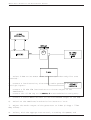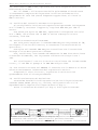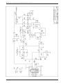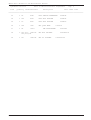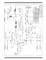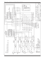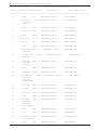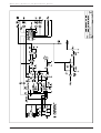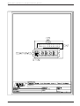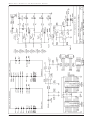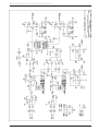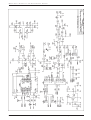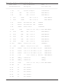
1
TEX20-NV/S
TECHNICAL AND MAINTENANCE MANUAL
MANUALE TECNICO E DI MANUTENZIONE
Manufactured by R.V.R. Elettronica - Italy
TEX20-NV/S Technical and Maintenance Manual
TEX20-NV/
S 20W FM STEREO EXCITER 87.5108 MHz RANGE
Technical and Maintenance Manual
TEX20-NV/
S ECCITATORE STEREO DA 20W RANGE 87.5108 MHz
Manuale Tecnico e di Manutenzione
English
Pag. 3
Italiano
Pag. 43
R.V.R. Elettronica S.r.l. (Bo)
Pag. 2
TEX20-NV/S Technical and Maintenance Manual
INDEX
Preliminary Instructions and Warranty Information
Safety Regulations
Pag. 5
Pag. 7
SECTION 1
General Description
Pag. 10
Technical Specifications (Table A)
Pag. 12
Dimensional & Environmental Specifications (Table B)
Pag. 14
SECTION 2
Electrical Description
Pag. 15
Front Panel Description
Pag. 18
Front Panel View (Fig.1)
Pag. 20
Rear Panel Description
Pag. 21
Rear Panel View (Fig.2)
Pag. 23
Top View Description
Pag. 24
Top View (Photo 1)
Pag. 25
Bottom View Description
Pag. 26
Bottom View (Photo 2)
Pag. 27
Block Diagram (Fig.3)
Pag. 28
Recommended Test Equipment (Table C)
Pag. 29
SECTION 3
Installation Procedures
Pag. 30
SECTION 4
Maintenance
Pag. 35
SECTION 5
Internal Adjustments
Pag. 38
APPENDIX A
Circuit Diagrams, Layouts and Bill of Material
R.V.R. Elettronica S.r.l. (Bo)
Pag. 83
Pag. 3
TEX20-NV/S Technical and Maintenance Manual
Wiring Diagram
Pag. 84
Main Card
Pag. 86
Power Supply
Pag. 99
CON-PA Card
Pag. 104
R.F. Power Amplifier
Pag. 108
Audio Input Card
Pag. 113
Stereo Coder (Mod. SDC30)
Pag. 117
Meter Card
Pag. 124
Frequency Selector Card (Mod. TSW-1)
Pag. 128
Frequency Selector Card (Mod. TSW-3)
Pag. 132
TCXO Card
Stereo Coder (Mod. SDC30A002)
R.V.R. Elettronica S.r.l. (Bo)
Pag. 136
Pag. 140
Pag. 4
TEX20-NV/S Technical and Maintenance Manual
PRELIMINARY INSTRUCTIONS
AND WARRANTY INFORMATION
WARNING: This a "CLASS A" equipment. In a residential place this equipment
can cause hash. In this case can be requested to user to take the necessary
measures.
Please observe safety precautions when handling this unit. This equipment
contains dangerous currents and high voltages.
This manual is written as a general guide for those having previous knowledge
and experience with this kind of equipment. It is not intended to contain a
complete statement of all safety warnings which should be observed by personnel
in using this or other electronic equipment.
R.V.R. doesn’t assume responsibility for injury or damage resulting from
improper procedures or practices by untrained/unqualified personnel in the
handling of this unit.
Please observe all local codes and fire protection standards in the operations
of this unit.
CAUTION: always disconnect power before opening covers or removing any part
of this unit. Use appropriate grounding procedures to short out capacitors
and high voltage points before servicing.
Any damage to the goods must be reported to the carrier in writing on the
shipment receipt.
Any discrepancy or damage discovered subsequent to delivery, shall be reported
to R.V.R. within five (5) days from its receipt.
R.V.R. extends to the original end-user purchaser all original manufacturers
warranties which are transferable and all claims are to be made directly to
R.V.R. per indicated procedures.
All manufacturers warranties will be supported by R.V.R. to ensure precise
and speedy service where possible.
R.V.R. shall not be liable for any damage of whatsoever nature, arising out
of or in connection with the product or its use thereof.
R.V.R.'s warranty shall not include:
1)
2)
3)
4)
5)
Re-shipment of the unit to R.V.R. for repair purposes
Any unauthorized repair/modification
Incidental/consequential damages as a result of any defect
Nominal non-incidental defects
Re-shipment costs or insurance of the unit or replacement
units/parts
R.V.R. Elettronica
S.r.l.
(Bo)
5
Warranty
shall come
into
force from invoice date and for Pag.
the period
of the
manufactures warranty.
TEX20-NV/S Technical and Maintenance Manual
The warranty for a period of 12 months is referred to any R.V.R.
product, while for products as Transistors, Mos-Fet and Tubes of the
final stages is applied the manufacture's warranty of these devices.
To claim your rights under this warranty:
a. Contact the dealer or distributor where you purchased the unit.
Describe the problem and ask if he has an easy solution. Dealers
and Distributors are supplied with all the information about
problems that may occur and usually they can repair the unit quicker
than what the manufacturer could do. Very often installing errors
are discovered by dealers.
b.
If your dealer cannot help you, contact R.V.R. in Bologna and explain
the problem. If it is decided to return the unit to the factory,
R.V.R. will mail you a regular authorization with all the necessary
instructions to send back the goods.
c. When you receive the authorization, you can return the unit. Pack
it carefully for the shipment, preferably using the original packing
and seal the package perfectly. The customer always assumes the
risks of loss (i.e., R.V.R. is never responsible for damage or loss),
until the package reaches R.V.R. premises. For this reason, we
suggest you to insure the goods for the whole value. Shipment must
be
effected C.I.F. (PREPAID) to the address specified by R.V.R.’s
service manager on the authorization.
DO NOT RETURN UNITS WITHOUT OUR AUTHORIZATION AS THEY WILL BE
REFUSED.
Be sure to enclose a written technical report where mention all the problems
found and a copy of your original invoice establishing the starting date of
the warranty.
Replacement and warranty parts may be order from the following address. Be
sure to include the equipment model and serial number as well as part
description and part number.
R.V.R. Elettronica S.r.l.
Broadcasting Equipment Via del Fonditore, 2/2c
40138 Bologna - Italy
-
R.V.R. reserves the right to modify the design and specifications of the
equipment in this manual without previous notice.
R.V.R. Elettronica S.r.l. (Bo)
Pag. 6
TEX20-NV/S Technical and Maintenance Manual
WARNING!
The currents and voltages in this equipment are dangerous!
Personnel must at all times observe safety regulation!
This manual is intended as a general guide for trained and qualified personnel
who are aware of the dangers inherent in handling potentially hazardous
electrical and electronic circuits.
It is not intended to contain a complete statement of all safety precautions
which should be observed by personnel in using this or other electronic
equipment.
The installation, operation, maintenance and service of this equipment
involves risks both to personnel and equipment, and must be performed only
by qualified personnel exercising due care.
R.V.R. ELETTRONICA S.r.l. shall not be responsible for injury or damage
resulting from improper procedures or from the use of improperly trained or
inexperienced personnel performing such tasks.
During installation and operation of this equipment, local building codes and
fire protection standards must be observed.
WARNING!
Always disconnect power before opening covers,
doors, enclosures, gates, panels or shields.
Always use grounding sticks and short out high
voltage points before servicing. Never make
internal adjustments, perform maintenance or
service when alone or when fatigued.
Do not remove, short-circuit or tamper with interlock switches on access
covers, doors, enclosures, gates, panels or shields.
Keep away from live circuits, know your equipment and don’t take chances.
WARNING!
In case of emergency ensure that power has been disconnected
R.V.R. Elettronica S.r.l. (Bo)
Pag. 7
TEX20-NV/S Technical and Maintenance Manual
Treatment of electrical Shock
1) If victim is not responsive follow the A-B-C's of basic life support.
PLACE VICTIM FLAT ON HIS BACK ON A HARD SURFACE
A AIRWAY
B BREATHING
IF UNCONSCIOUS,
OPEN AIRWAY
IF NOT BREATHING,
BEGIN ARTIFICIAL
BREATHING.
LIFT UP NECK,
PUSH FOREHEAD BACK,
CLEAR OUT MOUTH IF NECESSARY,
OBSERVE FOR BREATHING
TILT HEAD,
PINCH NOSTRILS,
MAKE AIRTIGHT SEAL,
4 QUICK FULL BREATHS.
REMEMBER MOUTH TO MOUTH
RESUSCITATION MUST BE
COMMENCED AS SOON AS
POSSIBLE.
C CIRCULATION
CHECK CAROTID PULSE
IF PULSE ABSENT,
BEGIN ARTIFICIAL
CIRCULATION
DEPRESS STERNUM 1 1/2" TO 2"
APPROX. 80 SEC. : ONE RESCUER, 15 COMPRESSIONS,
2 QUICK BREATHS.
APPROX. 60 SEC. : TWO RESCUERS, 5 COMPRESSIONS,
1 BREATH
SIONS
NOTE: DO NOT INTERRUPT RHYTHM OF COMPRESWHEN SECOND PERSON IS GIVING BREATH.
Call for medical assistance as soon as possible.
2) If victim is responsive:
a. Keep them warm.
b. Keep them as quiet as possible.
c. Loosen their clothing (a reclining position is recommended).
R.V.R. Elettronica S.r.l. (Bo)
Pag. 8
TEX20-NV/S Technical and Maintenance Manual
FIRST-AID
Personnel engaged in the installation, operation,
maintenance or servicing of this equipment are urged
to become familiar with first-aid theory and practices.
The following information is not intended to be a
complete first-aid procedure, it is brief and is only
to be used as a reference. It is the duty of all
personnel using the equipment to be prepared to give
adequate Emergency First Aid and thereby prevent
avoidable loss of life.
Treatment of electrical Burns
1) Extensive burned and broken skin.
a. Cover area with clean sheet or cloth.
(Cleansed available cloth article).
b. Do not break blisters, remove tissue, remove adhered particles of
clothing, or apply any salve or ointment.
c. Treat victim for shock as required.
d. Arrange transportation to a hospital as quickly as possible
e. If arms or legs are affected keep them elevated.
NOTE
If medical help will not be available within an hour and the victim is conscious
and not vomiting, give him a weak solution of salt and soda: 1 level teaspoonful
of salt and 1/2 level teaspoonful of baking soda to each quart of water (neither
hot or cold).
Allow victim to sip slowly about 4 ounces (half a glass) over a period of 15
minutes.
Discontinue fluid if vomiting occurs (Do not give alcohol).
2) Less severe burns - (1st & 2nd degree)
a. Apply cool (not ice cold) compresses using the cleansed available
cloth article.
b. Do not break blisters, remove tissue, remove adhered
particles of clothing, or apply salve or ointment.
c. Apply clean dry dressing if necessary.
d. Treat victim for shock as required.
e. Arrange transportation to a hospital as quickly as possible.
f. If arms or legs are affected keep them elevated.
R.V.R. Elettronica S.r.l. (Bo)
Pag. 9
TEX20-NV/S Technical and Maintenance Manual
SECTION 1
GENERAL DESCRIPTION
1.1 GENERAL DESCRIPTION
The TEX20-NV/S is housed in a 3U, 19" rack-mouting container comprising
a number of interconnected modules mounted internally on the main chassis,
facilitating removal and substitution.
The power output control, audio input level control and analog meter for the
measurement of operating parameters, are all mounted on the front panel.
The line power, audio input, RF output and telemetry control connectors are
mounted on the rear panel.
1.2 ELECTRICAL DESCRIPTION
The TEX20-NV/S is an exciter working in the 87.5 to 108 MHz band,
programmable in steps of 10 KHz. Its power output is continuously adjustable
from 2 to 20W into a 50 Ohm load.
The TEX20-NV/S incorporates a stereo coder which guarantees excellent stereo
separation together with low harmonic distortion. It also accepts two SCA
signals.
A front panel switch allows stereo operation or "mono/mpx" operation which
excludes the stereo encoder and uses the "right" input as the mono input and
the "left" input as the wideband composite input.
The specification features low audio distortion and intermodulation figures
(typically 0.05%) and a high signal-to-noise ratio (typically -72 dB).
A voltage selector on the transformer primary allows a variety of supply
voltages to be used.
1.3 METERS AND INDICATORS
The operating parameters of the exciter can be monitored using the analog
multimeter (12 Fig.1) situated on the front panel.
The parameter to be measured is selected by the rotary selector
(11 Fig.1).
The frequency control (14 Fig.1) allows frequencies to be selected in steps
of 10 KHz.
Three red alarm leds indicate VCO unlock (15 Fig.1), excess VSWR (8 Fig.1)
on the output and the shutdown condition, programmed by a remote computer.
Three green leds (7 Fig.1) indicate the presence of +12V, +15V and +28V voltages
which are used to power the various cards inside the exciter.
A selector (1 Fig.1) allows selection between Mono/MPX and Stereo functions
and another selector (6 Fig.1) is provided to choose the level of the input
signal.
Trimmers (5 Fig.1) are provided for adjustment of left and right channels and
a switch allows the stereo subcarrier to be enabled or disabled.
1.4 AUTOMATIC FREQUENCY CONTROL
R.V.R. Elettronica S.r.l. (Bo)
Pag. 10
TEX20-NV/S Technical and Maintenance Manual
The operating frequency is governed by a thermally-compensated, reference
oscillator working within a phase-locked loop (PLL).
The TEX20-NV/S reaches frequency lock within a maximum of 30 seconds.
1.5 CONTROL CIRCUITS
The control circuits allow automatic control of output power, maintaining
the chosen power level across the entire operating band. Furthermore another
circuit protects the final stage against excessive VSWR or short circuits.
1.6 RF AMPLIFIER
The RF amplifier is a wide-band design and guarantees an adjustable power
output of 2 to 20 watts across the entire band.
A low-pass filter enables the TEX20-NV/S to be used as a low power transmitter,
connected directly to an antenna.
1.7 SPECIFICATIONS
Please refer to Table A for the electrical specifications and
Table B for the mechanical specifications.
TABLE A
R.V.R. Elettronica S.r.l. (Bo)
Pag. 11
TEX20-NV/S Technical and Maintenance Manual
TECHNICAL SPECIFICATIONS
Power Supply
100-130V, 50-60Hz
198-250V, 50-60Hz
Power Consumption
approx. 130 W
Cooling System
Forced ventilation
Frequencies
from 87.5 to 108 MHz in steps of
10 KHz, microprocessor-controlled
Output Power
adjustable from 2 to 20 W
Automatic Output
Stabilizes the set RF output level
control
Output Impedance
50 Ohm
Output Connector
Standard "N-type"
Harmonic Suppression
meets or exceeds all FCC and CCIR
requirements (> -65dB)
Spurious Signal Suppression
meets or exceeds all FCC and CCIR
requirements (> -80 dB)
Mono Intermodulation Distortion
0.05% or less, measured at 1KHz
and 1.3 KHz, ratio 1:1 at 100%
modulation
Frequency Stability
Modulation Type
± 500Hz (typically ± 300Hz) from
0 to 50°C
Direct frequency modulation of the
RF oscillator at fundamental
frequency
Frequency Deviation
±75KHz nominal
Harmonic distortion
< 0.10% (typically 0.05%)
Pre-emphasis
50µs ± 2% or 75µs ± 2% selectable
Residual AM (asynchronous)
65dB below reference carrier with
100% amplitude modulation at
R.V.R. Elettronica S.r.l. (Bo)
Pag. 12
TEX20-NV/S Technical and Maintenance Manual
400Hz, without de-emphasis, no FM
modulation present
Residual AM (synchronous)
55dB below reference carrier with
100% amplitude modulation at
400Hz, without de-emphasis, FM
modulation = ±75KHz at 400Hz
FM Signal-to-Noise
> 75 dB mono, > 70 dB stereo
measured with 75 KHz deviation in
the 30 Hz to 15 KHz band RMS.
Audio Input Impedance
10 KOhm balanced or 5K Ohm
unbalanced (600 Ohm on request)
Audio Input Level
Selectable from -12 to +9 dBm in
five steps
Audio Frequency Range
30-15000 Hz, MONO input
30-100000 Hz, MPX input
Audio Input Filter
> or = at 45dB at 19KHz (Mono)
Mono Frequency Response
±0.3dB from 30Hz to 15KHz
MPX Frequency Response
±0.3dB from 30Hz to 100KHz
Stereo Separation
> 45dB (typically 50dB)
Pilot Tone Frequency
19KHz ±1Hz
Pilot Tone Level
-20dBm adjustable
Number of SCA Inputs
2
SCA Input Impedance
1KOhm unbalanced
SCA Input Level
0dBm for ±7.5KHz of deviation
SCA Input Response
±0.5dBm from 40KHz to 100KHz
TABLE B
R.V.R. Elettronica S.r.l. (Bo)
Pag. 13
TEX20-NV/S Technical and Maintenance Manual
DIMENSIONAL AND ENVIRONMENTAL SPECIFICATIONS
Rack Dimensions
483.0 mm (19")W
132.5 mm (5.22")H
345.0 mm (13.58")D
Operating Temperature
-10°C to 50°C
Humidity
95% max. non-condensing
Weight
13Kg
SECTION 2
R.V.R. Elettronica S.r.l. (Bo)
Pag. 14
TEX20-NV/S Technical and Maintenance Manual
ELECTRICAL DESCRIPTION
2.1 INTRODUCTION
This section describes, in detail, the operating theory behind the TEX20NV/S.
To aid understanding, the unit has been subdivided into blocks, each of which
is fully described below. The block diagram is show in Fig.3.
2.2 POWER SUPPLY
This circuit comprises a board (5 Photo 1), mounted on a heat sink, which
is fixed to the central part of the middle section of the unit.
The power supply generates the various stabilized voltages necessary for each
of the various modules that make up the TEX20-NV/S.
After having undergone filtering for mains-borne interference, the supply is
transformed into four lower voltages, rectified, smoothed and stabilized to
the following values: +12V, +15V and 2 to 24V variable (+28V upstream of the
voltage control stage).
The +15V supplies the encoder mixer, the main card, the meter card and the
contraves card. The +12V supplies the RF power amplifier driver and the 224V variable supplies the final power stage of the same module.
The variable voltage of the final stage is controlled by the PWR ADJ control
which determines the RF power output of the exciter.
The automatic control of output power guarantees the power level set by the
PWR ADJ control right across the frequency range and independently of other
variables such as temperature, load variations etc.
The system works by comparing the value set by the PWR ADJ control with the
actual power output of the unit and compensating accordingly.
A power limiting circuit intervenes in the event of excess SWR on the output,
thus protecting the final stage.
2.3 AUDIO INPUT CARD
This card (2 Photo 2) is situated on the rear panel of the exciter.
The card filters all audio signal inputs to the unit, removing RF interference,
before supplying them to the encoder mixer.
The main operating parameters of the exciter are available for remote
monitoring via a 10 pin connector.
2.4 ENCODER MIXER
This card (1 Photo 1) is situated in the lower part of the unit.
The card can function either as a stereo encoder or as a simple mixer for the
various audio inputs. The function may be selected by a control situated on
the front panel.
In stereo encoder mode, the 19KHz pilot tone is derived from a quartz crystal
reference oscillator.
R.V.R. Elettronica S.r.l. (Bo)
Pag. 15
TEX20-NV/S Technical and Maintenance Manual
So too is the sampling frequency which allows the L and R signals to be separated
from the multiplexed signal, plus the suppression of the 38KHz frequency.
The level of the left and right signals is set by the corresponding selector
situated on the front panel. The signals are then filtered at 15KHz and preemphasized (50 µS CCIR, 75 µS FCC) before being sent to the multiplex circuit.
The audio signals from the two SCA inputs are mixed in to provide the output.
In mixer mode (Mono/MPX) the stereo encoder is bypassed, the right input accepts
a mono signal and the left input accepts a multiplex signal upto 100KHz. The
SCA inputs remain unchanged.
Three rectifiers allow the peak levels of the two inputs "LEFT/MPX" and "RIGHT/
MONO" to be displayed on the analog meter, and provide the audio detector
circuit with the deviation level.
2.5 MAIN CARD
The main card (1 Photo 1) is situated internally, in the upper part of
the unit.
The circuit includes a voltage-controlled oscillator (VCO, 2 Photo 1) which
generates the selected operating frequency.
This signal is amplified to drive the phase-locked loop (PLL) control circuit
and also the final stage.
The audio signal supplied by the encoder mixer is amplified and processed in
order to compensate for distortion caused by the varicap diodes; it is then
injected into the VCO to provide class F3E modulation.
The operating frequency generated by the VCO is divided down before being
compared to a reference frequency, generated by a high stability oscillator
(standard 5 ppm). The error voltage is filtered and used to compensate the
VCO frequency and guarantee its stability.
An indicator situated on the front panel signals the “unlocked” condition.
Three trimmers are present on this card for adjustment of deviation, distortion
and pre-polarization of the varicaps.
2.6 RF POWER AMPLIFIER
The final power stage (4 Photo 1) is mounted on a heat sink to dissipate
waste heat and is enclosed in a totally screened, metal container, fixed to
the upper-middle part of the central section of the unit.
The RF signal coming from the Main card at a power level of about
150-200 mW, reaches the driver stage (MRF237 in Class C) and is amplified to
a level of about 2W before being further amplified by the final stage (BLW86)
to a level of upto 20W.
The resultant signal is then filtered by a low-pass filter which removes any
harmonic content.
A directional coupler allows the direct and reflected power levels to be
measured and displayed on the analog multimeter and also feedback to the power
supply for automatic control of the output power (see Power Supply sec. 2.2).
A BNC connector situated on the rear panel provides a power signal at -30dB
of the amplifier output power.
R.V.R. Elettronica S.r.l. (Bo)
Pag. 16
TEX20-NV/S Technical and Maintenance Manual
2.7 METER CARD
This card (3 Photo 2) is situated centrally on the front panel.
The card receives direct and reflected power signals from the power supply
which, in turn, come from the final power stage. The Stereo encoder card
supplies deviation and left and right signal levels.
These signal levels are then displayed on the analog meter according to the
position of the rotary selector situated on the front panel.
2.8
FREQUENCY SELECTOR CARD
This card (3 Photo 1) is fixed to the left-hand side of the front panel.
The operating frequency selected by the frequency control is represented by
a signal which is supplied to the frequency dividers that form part of the
PLL circuits found on the Main card.
2.9 CLIPPER CARD (OPTIONAL)
This card is fixed with a sandwich structure on the coder card and is
accessible from lower part of the equipment.
Its function is that to limit drastically any audio signal that exceeds a
prefixed threshold.
Therefore, it's used to avoid any type of over-modulation as to maximum peak
permitted of ±75KHz.
With an exceeding signal, immediately too, of 6dB the nominal level for a
deviation of ±75KHz, this card allows to contain deviation increasing within
1dB.
SECTION 3
INSTALLATION PROCEDURE
3.1 INTRODUCTION
This chapter contains the information required for installation of the
R.V.R. Elettronica S.r.l. (Bo)
Pag. 17
TEX20-NV/S Technical and Maintenance Manual
FRONT PANEL VIEW DESCRIPTION (FIG.1)
1
STEREO/MONO-MPX
Selects STEREO or MONO/MPX operation
2
STEREO LED
Indicates the operation of the stereo
encoder
3
19KHz Led
Indicates the 19KHz pilot tone presence
4
MODE SELECTOR
Button In :
Stereo Operation Mode
Pilot Tone Present
Button Out:
Mono Operation Mode
Pilot Tone Absent
5
L/MPX & R/MONO LEVEL
L/MPX and R/MONO input level adjustable
from -12 to +9 dBm; this is possibile if
the input level switch is completely
turned clockwise
6
INPUT LEVEL
7
VOLTAGES LEDS
8
SWR
Input signal attenuator adjustable in 5
steps from -9 to +6 dBm
Indicates the presence of the internal
operating voltages +12V, +15V and +28V
Indicates that reflected power exceeds
10W
9
PWR ADJ
10-turn trimmer to regulate the power
output of the exciter
10
REMOTE
11
MEASUREMENT SELECTOR
The measurement made by the meter
corresponds to the position of this
selector
12
METER
Indicate that the exciter has been
shut-down by remote control
Analog meter used to display the
following operating parameters of the
exciter:
Forward Power
f.s.
Reflected Power
Deviation
f.s.
Right Channel In. Level
Left Channel In. Level
R.V.R. Elettronica S.r.l. (Bo)
25W
f.s. 5W
100KHz
f.s. +3dB
f.s. +3dB
Pag. 18
TEX20-NV/S Technical and Maintenance Manual
13
POWER
ON/OFF switch
14
MHz/KHz (Frequency Selector) Rotary frequency selector
15
L.O. UNLOCK
If ON indicates that the VCO is not
locked to the reference frequency.
The output power will drop to zero in
this condition
R.V.R. Elettronica S.r.l. (Bo)
Pag. 19
TEX20-NV/S Technical and Maintenance Manual
FIG. 1
R.V.R. Elettronica S.r.l. (Bo)
Pag. 20
TEX20-NV/S Technical and Maintenance Manual
REAR PANEL VIEW DESCRIPTION (FIG.2)
1
REMOTE CONTROL
BNC connector. Connecting the central
conductor to ground will cause the RF
output power level to drop to zero and
to
stay there until the short is
removed.
When used with an R.V.R.
amplifier, this
connector should be
connected to the
"REMOTE" output of the
power amplifier.
2
FAN
Fan-assisted cooling for the power stage
and the power supply.
3
TELEMETRY TERMINALS
1-2
3-10
4
5
6
7
8
9
4
PLUG
10 Pin telemetry connector.
Audio GND
GND
PD = Forward Power
PR = Reflected Power
VPA
IPA
SWR alarm
Unlock alarm
Line power connector.
5
FUSE BLOCK &
Fuse block and line voltage selector.
LINE VOLTAGE CHANGER
Use a small screwdriver to change the
fuse or the line voltage. Rotate the
block and position it for the desired
voltage.
6
24VDC (Optional)
Plugs for External 24VDC
7
R.F. OUTPUT
50 Ohm, "N-type" connector
8
T.P. -30dB
-30dB output referred to the output
power level
9
RIGHT (MONO)
Cannon XLR for CCIR version with
balanced input.
1
GND
2
(+) Inphase
3
(-) Return
10
LEFT (MPX)
11
SCA 1
Cannon XLR for CCIR version with
balanced input.
1
GND
2
(+) Inphase
3
(-) Return
BNC connector, unbalanced SCA1 input
R.V.R. Elettronica S.r.l. (Bo)
Pag. 21
TEX20-NV/S Technical and Maintenance Manual
12
SCA 2
BNC connector, unbalanced SCA2 input or
output (internally selectable) for pilot
tone (i.e. for RDS encoder)
R.V.R. Elettronica S.r.l. (Bo)
Pag. 22
TEX20-NV/S Technical and Maintenance Manual
FIG. 2
R.V.R. Elettronica S.r.l. (Bo)
Pag. 23
TEX20-NV/S Technical and Maintenance Manual
TOP VIEW DESCRIPTION (PHOTO 1)
1
.................. Main Card
2
.................. V.C.O.
3
.................. Frequency Selector Card
4
.................. R.F. Power Amplifier Stage
5
.................. Power Supply
6
.................. Transformer
R.V.R. Elettronica S.r.l. (Bo)
Pag. 24
TEX20-NV/S Technical and Maintenance Manual
4
5
1
2
6
3
PHOTO 1
R.V.R. Elettronica S.r.l. (Bo)
Pag. 25
TEX20-NV/S Technical and Maintenance Manual
BOTTOM VIEW DESCRIPTION (PHOTO 2)
1
.................. Stereo Coder Card
2
.................. Audio Input Card
3
.................. Meter Card
R.V.R. Elettronica S.r.l. (Bo)
Pag. 26
TEX20-NV/S Technical and Maintenance Manual
3
1
2
PHOTO 2
R.V.R. Elettronica S.r.l. (Bo)
Pag. 27
TEX20-NV/S Technical and Maintenance Manual
FIG. 3
R.V.R. Elettronica S.r.l. (Bo)
Pag. 28
TEX20-NV/S Technical and Maintenance Manual
TABLE C
RECOMMENDED TEST EQUIPMENT
INSTRUMENT TYPE
SUGGESTED MODEL
Coaxial Load Resistor
Bird
Mod. 8085
Wattmeter
Mod. 43
Bird
Plug-in-Elements
Bird
Mod. 25B
TECHNICAL SPECIFICATIONS
Power rating 50W continuous
Power range : 100mW to 10KW
using Bird Plug-in-Elements
Frequency range : 0.45 to
2300MHz
Variable RF Signal Bird
Sampler Element
Mod. 4275-100
Power rating : 25W
Freq. range : 25 to 125MHz
Power rating : 1000W
Freq. range : 25 to 1000MHz
Spectrum Analyzer
Adavntest
Mod. R4141D
10KHz-3.5GHz
Low Distortion
A.F. Genarator
Krohn-Hite
Mod. 4400A
THD < 0.001%
Oscilloscope
Tektronix
Mod. 2225
50MHz Oscilloscope
Stereo Decoder
A.E.V.
Mod. SMD
Stereo separation
> 60dB 30Hz to 15KHz
F.M. Modulation Meter
Rohde Schwarz
Mod. F.A.M.
Digital Multimeter Metrix
R.V.R. Elettronica S.r.l. (Bo)
Pag. 29
TEX20-NV/S Technical and Maintenance Manual
TEX20-NV/S exciter and for preliminary checks.
3.2 UNPACKING
Remove the unit from its packaging and before any other operation, check
for any damage that the unit may have suffered in transit and that all front
and rear panel controls are functioning.
3.3 INSTALLATION
1) Check that the line voltage selector is correctly set for the local
supply. If not, remove the cover on which the voltages are printed
and rotate it until the required value corresponds to the arrow,
and reinsert it. Check also that the fuse mounted inside the cover
is
present and in order.
The current capacity of the fuse are as follows:
220-240 V - 1.6 A
100-120 V - 2.0 A
2)
Now ensure that the PWR ADJ control is rotated fully anti- clockwise,
using a small screwdriver.
N.B. The control is a ten-turn potentiometer so care should be taken
to verify the minimum position.
Units are usually shipped with this control already at minimum.
WARNING: When the unit is switched on with the control at its
minimum position, power output is about 2W.
3) Connect a dummy load with a power rating of at least 20W continuous
to the RF output, situated on the rear panel of the unit (see SETUP1).
It is advisable to connect a bypass wattmeter in series with this
load in order to verify the accuracy of the unit’s own internal
wattmeter.
SETUP
1 REMOTE connector on the rear
4) Connect a switch, via a cable,
to the
panel so that the switch is able to short the central conductor to
its screen. Leave the switch in the short-circuit position.
R.V.R. Elettronica S.r.l. (Bo)
Pag. 30
TEX20-NV/S Technical and Maintenance Manual
5)
Switch the unit’s on/off switch to the OFF position.
6)
Connect line power to the unit via the VDE socket.
N.B. It is essential that the unit be properly earthed to ensure both the safety
of the operator as well as the correct functioning of the equipment.
7) Switch the power switch to the ON position and check that the both
the green ON led and the red UNLOCK led are both on.
Select the desired operating frequency using the corresponding
selector.
The red UNLOCK led should switch off within 30 seconds, indicating
that the oscillator has locked onto the operating frequency.
The frequency selector comprises five figures of which the three
to the left of the decimal point represent (from left to right)
hundreds of MHz, tens of MHz and MHz.
The two figures to the right of the decimal point represent (from
left to right) hundreds of KHz and tens of KHz.
Eg: 098.45 = ninety eight megahertz and four hundred and fifty
Kilohertz.
Eg: 103.94 = one hundred and three Megahertz and nine hundred and
forty Kilohertz.
Furthermore, if a frequency is selected beyond the two limits of
the 87.5-108 MHz band, the amplifier will continue to work even
though the displayed frequency no longer corresponds to the
operating frequency of the unit.
8) After having verified that the UNLOCK led is switched off and that
the unit is therefore locked to the selected operating frequency,
switch the switch connected to the REMOTE connector so as to remove
the short circuit between the central conductor and ground.
The RF output is now enabled and should correspond to a power level
of about 2W.
To check this reading, select FWD on the meter selector and read
the power from the 25W FSD scale.
9) Using a small screwdriver, rotate the PWR ADJ control clockwise;
the power output should increase progressively to a maximum of 20W.
Check the value with the bypass wattmeter which should be within
±10%.
10) With the power output at 20W, select a new operating frequency well
away from the current value.
Eg: 107 MHz: the UNLOCK led should switch on and the power output
should fall to zero at the same time. Only when the UNLOCK led
switches off (unit locked to new frequency) should the power output
resume its previous level.
11) Automatic power control check.
It is advisable to start this procedure with the operating frequency
R.V.R. Elettronica S.r.l. (Bo)
Pag. 31
TEX20-NV/S Technical and Maintenance Manual
set to 87.50 MHz. When locked to this frequency, the PWR ADJ control
should be adjusted for an output power of 10W.
Now, with no further adjustment of the PWR ADJ control, change the
operating frequency in steps of 4-5 MHz, ensuring that the output
power remains constant at 10W.
12) SWR alarm check.
For this test, adjust the PWR ADJ control for a power output of 5W.
Disconnect the output load and check that the S.W.R. led switches
on.
Now adjust the PWR ADJ control to check that the unit switches on
again at a reflected power level of about 4W.
Turn the PWR ADJ control for maximum power and check that the
reflected power does not exceed 10W.
Re-connect the output load and check that REF falls to zero, the
SWR led switches off and that PWR FWD jumps to 20W.
13) Now short circuit the central conductor of the REMOTE input to ground
and the output power should drop instantly to zero.
Removing the short should cause the power output to return,
gradually, to its previous level.
14) Deviation reading check.
The maximum input sensitivity is determined by the position of the
"INPUT LEVEL" control. In the -12/+9 position, the sensitivity will
depend on the L/mpx and R/mono controls.
Put the meter selector in the DEV position.
15) Connect a low-distortion audio generator to the LEFT and RIGHT
inputs (see SETUP2).
Inject a 400 Hz tone at a level of 0dBm (775mV RMS = 2.2Vpp).
Put the INPUT LEVEL control in the 0dBm position.
Select stereo mode (the corresponding led will switch on).
Enable the PILOT using the relevant switch (the green led will switch
on).
With the selector in the R/MONO
position,
check that the reading
SETUP
2
is 0db, measured on the +3dB FSD scale.
Repeat the operation for the L/MPX.
Check that the deviation reading is 100%.
3.4 OPERATION USING THE INTERNAL STEREO ENCODER
1)
Inject the pilot tone (4 Fig.1) checking that the corresponding led
R.V.R. Elettronica S.r.l. (Bo)
Pag. 32
TEX20-NV/S Technical and Maintenance Manual
switches on.
2)
Select STEREO operation confirmed by the corresponding led.
3) Select the sensitivity of the audio LEFT/RIGHT inputs to match the
signal level being supplied to the unit.
4) Connect the signal source to the LEFT/RIGHT inputs. These are
balanced inputs (see SETUP3).
5)
Check with the analog multimeter that the L/R signal levels are those
expected, selecting the desired input with the corresponding
control.
6) The effective modulation level
may be
SETUP
3 measured on the analog
multimeter by selecting DEV with the corresponding selector.
3.5 CONNECTION OF AN EXTERNAL STEREOPHONIC SOURCE
1)
Connect the stereo source’s output to the MPX input of the unit (see
SETUP4).
2)
Adjust the stereo encoder to obtain just the 19 KHz subcarrier output
and ensure the total absence of signals on the left and right inputs
of the encoder.
3) Adjust the output level of the encoder to obtain the correct level
as displayed on the analog meter of the TEX20-NV/S.
4) Inject audio signals into theSETUP
left and
4 right inputs of the encoder
and adjust the sensitivity of the input to obtain a peak reading
of
MAX=75KHz with both channels enabled.
3.6 MONOPHONIC TRANSMISSION
R.V.R. Elettronica S.r.l. (Bo)
Pag. 33
TEX20-NV/S Technical and Maintenance Manual
1) Connect the signal source (audio mixer, receiver, compressor etc.)
to the MONO input. This input is unbalanced (see SETUP5).
2) Select the desired INPUT LEVEL.
3)
Adjust the signal level of the equipment connected to the
TEX20-NV/S (with the audio signal present) for a peak reading of
DEV MAXIMUM = 75 KHz.
Note that international standards permit a maximum deviation (DEV MAX) of 75
KHz for frequency modulated, radiophonic
SETUP 5transmissions.
Exceeding this limit will only result in the degradation of signal quality.
In the case of mono transmissions, the stereo input is available for frequencies
between 15 KHz and 100 KHz ie. subcarriers for SCA, RDS etc.
SECTION 4
MAINTENANCE
4.1 SAFETY REQUIREMENTS
WARNING WARNING WARNING WARNING WARNING WARNING WARNING WARNING
When the exciter is operational, removing the top cover will expose lethal
R.V.R. Elettronica S.r.l. (Bo)
Pag. 34
TEX20-NV/S Technical and Maintenance Manual
voltages on the line voltage selector and heavy currents on the power supply
filter terminals and power transistors.
Use insulated tools for any type of maintenance work and do not touch any
internal components when the exciter is switched on.
Ensure that the exciter is disconnected from the line supply before carrying
out any maintenance work.
MAINTENANCE LEVEL
1
4.2 ROUTINE MAINTENANCE
The only routine maintenance required by the TEX20-NV/S is the periodic
replacement of the cooling fan and the removal of accumulated dust.
The period between such action will depend on ambient operating conditions
such as temperature, air-borne dust levels and humidity.
It is advisable to check the unit every 6 months and to replace noisy or worn
fans. Fans should be replaced as a matter of course after no more than 18 months
of operation.
MAINTENANCE LEVEL 2
4.3 STEREO ENCODER CARD REPLACEMENT
1)
Open the top and bottom covers of the unit.
2)
Disconnect connectors J1, J3 and J4.
3)
Unscrew the four nuts fixing the card.
4)
Unscrew the screw inside the INPUT LEVEL knob and slide it off.
5) Raise the card from its supports, simultaneously sliding the
switches and the INPUT LEVEL switch pivot from the panel.
4.4 RF POWER AMPLIFIER MODULE REPLACEMENT
1)
2)
Open the top and bottom covers of the unit.
Disconnect connector CN1 on the "CON-PA" card connected to connector
CN2 of Meter Card.
3) Unscrew the three fixing screws situated on the lower part of
internal metal shelf.
4) Disconnect the screened cable connecting the RF Power Amplifier
module to the Main Card.
5)
Slide out the RF Power Amplifier.
R.V.R. Elettronica S.r.l. (Bo)
Pag. 35
TEX20-NV/S Technical and Maintenance Manual
4.5 MAIN CARD REPLACEMENT
1)
Open the top and bottom covers of the unit.
2)
Disconnect connectors CN1 and CN2.
3) Disconnect the screened cable connecting the Main Card to the RF
Power Amplifier module.
4)
Unscrew the nuts fixing the card.
5)
Remove the card upwards with great care.
4.6 AUDIO INPUT CARD REPLACEMENT
1)
Open the top and bottom covers of the unit.
2) Disconnect connectors CN6 and CN7. To ease removal, disconnect
connector CN2 situated on the Main Card first.
3) Unscrew the nuts of the two connectors BNC1 and BNC2 situated on
the rear panel.
4) Unscrew the two screws fixing the terminal block panel, situated
on the rear panel.
5) Desolder the six wires connecting the Audio Input Card to the two
audio connectors, RIGHT (mono) and LEFT (MPX).
6)
Slide the card out.
4.7 POWER SUPPLY MODULE REPLACEMENT
1)
Open the top and bottom covers of the unit.
2) Unscrew the three fixing screws situated on the lower part of the
internal metal shelf.
3)
Disconnect connector CN1 from the Power Supply.
4) Take careful note of the position of the various colored connecting
wires.
5)
Disconnect the REMOTE faston connector situated on the power supply.
6) Take careful note of the positions of the fastons connected to the
bridge rectifier.
7)
Disconnect fastons JP1 and JP2 situated on the bridge rectifier.
R.V.R. Elettronica S.r.l. (Bo)
Pag. 36
TEX20-NV/S Technical and Maintenance Manual
8)
Carefully lift out the power supply.
4.8 METER CARD REPLACEMENT
1)
Open the top and bottom covers of the unit.
2) Unscrew the nut inside the measurement selector situated on the
front panel and the selector fixing nut.
3)
Disconnect connectors CN1 and CN2 situated on the Meter card.
4)
Disconnect the fastons CN4 and CN5 and jumper CN3.
5) Remove the card paying careful attention to the various leds and
adjustments.
4.9 FREQUENCY SELECTOR CARD REPLACEMENT
1) Open the top cover of the unit.
2) Disconnect connector CN1 situated on the Contraves card.
3) Unscrew the two fixing screws on the front panel.
4) Remove the Contraves card.
SECTION 5
CALIBRATION PROCEDURE
5.1 STEREO ENCODER CALIBRATION
It will be necessary to check and recalibrate the following parameters
after replacement of the Stereo Encoder card (see SETUP6):
R.V.R. Elettronica S.r.l. (Bo)
Pag. 37
TEX20-NV/S Technical and Maintenance Manual
1) Select 0 dBm on the INPUT LEVEL selector (encoder and pilot tone
inserted).
2) Connect a low distortion, sine-wave, audio generator to the left
and right inputs.
3)
4)
Connect a 50 Ohm 25W load resistor to the RF output of the
TEX20-NV/S.
6 other modulation analyzer).
Connect the -30 dB tap to the SETUP
FAM (or
5)
Connect a stereo MEAS-decoder to the rear FM-MPX output of the FAM.
6)
Switch on the TEX20-NV/S and wait for the PLL to lock.
7) Adjust the audio output of the generator to 0 dBm (2.2Vpp = 775mV
RMS, 400Hz).
8)
Select, with the appropriate control, a reading of R(MONO) and
R.V.R. Elettronica S.r.l. (Bo)
Pag. 38
TEX20-NV/S Technical and Maintenance Manual
adjust P8 on the encoder to obtain 0 dB.
8A) Repeat the operation for L(MPX), adjusting P7.
9) With the FAM in FM, P+ mode, and with a 30Hz-200KHz audio filter,
check that the deviation is 75KHz. If not, adjust trimmer R35,
situated on the Main card, accordingly.
9A) Remove the audio signal from both channels, leaving the pilot tone
inserted, and check that the deviation is between 6.5KHz and 8KHz
(typically 7.5KHz). Adjust P6 if necessary.
10) Remove the audio signal from one channel.
N.B. Check that the generator output is still at 0db.
Now measure the stereo separation with the Stereo Meas-Decoder, which, with
a 400Hz signal, should be better than 45dB.
Repeat the operation for the other channel.
Should the separation figure be different for the two channels (a difference
of upto 3dB is acceptable), adjust trimmer P4 on the Encoder card accordingly.
5.2 MAIN CARD CALIBRATION
After having replaced the Main Card and relevant connectors, carry out
the following procedure (see SETUP6, previous page):
1)
Connect an audio generator to the Left input (or Right).
2) Select 0 dBm on the INPUT LEVEL selector (encoder and pilot tone
inserted).
3)
Connect a 50 Ohm 25W load resistor to the RF output.
4)
Connect the FAM or other modulation analyzer to the -30dB tap.
5)
Connect a Stereo MEAS decoder to the rear output of the FAM "FM MPX".
6)
Inject a 400Hz, 0dBm (775Vrms, 2.2Vpp) tone into the Left (or Right)
input.
7) Configure the FAM to measure deviation with the "30Hz-200KHz/FM/
P+" filters and check that it is 75KHz.
If not, adjust trimmer R35 accordingly.
Check that the deviation remains constant right across the band and,
if not, adjust trimmer R36 on the Main Card, accordingly.
8) Remove the pilot tone with the switch, configure the FAM to measure
distortion and adjust trimmer R34 to minimize distortion.
N.B. The audio generator used in these tests must have a distortion
figure better than 0.001%.
R.V.R. Elettronica S.r.l. (Bo)
Pag. 39
TEX20-NV/S Technical and Maintenance Manual
Perform this test at the operating frequency of the exciter.
9)
Repeat step (7).
10) Repeat the same procedure from step (2) for the Right (or Left)
input.
5.3 RF POWER AMPLIFIER MODULE CALIBRATION
After having replaced the amplifier, carry out the following procedure
(see SETUP7):
1) Connect a bypass wattmeter between the RF output and a 50 Ohm 25W
dummy load.
2) Switch on the exciter and set the frequency to 98.00MHz. Wait for
the PLL to lock and the power output to be enabled.
3)
Rotate the PWR ADJ trimmer clockwise to obtain maximum power output.
4) Take a reading of the output power. If this is not 20 W, adjust
SETUP
7
trimmer R1 on the Power Supply card
accordingly.
5) Take the same reading from the analog meter on the TEX20-NV/S,
selecting PWR FWD. Adjust trimmer R8 on the Meter card for a meter
reading of 20W.
6) Disconnect the dummy load from the exciter output, check for a power
reduction of about 8W and the lighting of the SWR indicator.
Connect a voltmeter between telemetry terminal block connectors PD
and PR and adjust R2 on the power supply card for a voltage of 0V
±
0.1V.
7)
Rotate the PWR ADJ trimmer anticlockwise to obtain a FWD PWR reading
of 25 W. Select the PWR REF reading. Adjust R7 on the Meter 100 for
a reading of 25W fsd.
8)
Reconnect the dummy load and rotate the PWR ADJ trimmer clockwise
R.V.R. Elettronica S.r.l. (Bo)
Pag. 40
TEX20-NV/S Technical and Maintenance Manual
until the output power is once more 20W.
5.4 POWER SUPPLY CALIBRATION
The only calibration procedure required in the event of Power Supply
replacement is that of the RF Power Amplifier from step (1) to step (8).
5.5 AUDIO INPUT CARD CALIBRATION
No calibration is required after the replacement of this card.
5.6 FREQUENCY SELECTOR CARD CALIBRATION
No calibration is required after the replacement of this card.
5.7 METER CARD CALIBRATION
All meter readings should be calibrated after the replacement of any card:
Perform SETUP8.
1)
Inject a 400 Hz, 0dBm pilot tone into the Left (or Right) input.
2) Connect a bypass wattmeter between the RF output and a 50 Ohm, 25W
dummy load.
3) Adjust the power output to 15W.
4) With the selector, select the following measurements and make
adjustments according to the table below:
MEASUREMENT
R(MONO)
L(MPX)
FWD PWR
REF PWR
DEV
VALUE
0dB
0dB
20W
10W
VAR
+3dB
+3dB
25W
25W
100KHz
FSD
SETUP
8 TRIMMER
R6
R5
R8
R7
R4
NOTE
1
NOTE:
R.V.R. Elettronica S.r.l. (Bo)
Pag. 41
TEX20-NV/S Technical and Maintenance Manual
1) Disconnect the load for this measurement only and adjust PWR ADJ
for 10W of direct output power.
R.V.R. Elettronica S.r.l. (Bo)
Pag. 42
TEX20-NV/S Technical and Maintenance Manual
INDICE
Istruzioni Preliminari e Informazioni di Garanzia
Regole di Sicurezza
Pag. 44
Pag. 37
CAPITOLO 1
Descrizione Generale
Pag. 50
Caratteristiche Tecniche (Tabella A)
Pag. 52
Caratteristiche Dimensionali e Ambientali (Tabella B)
Pag. 54
CAPITOLO 2
Descrizione Elettrica
Pag. 55
Descrizione del Pannello Frontale
Pag. 58
Vista del Pannello Frontale (Fig.1)
Pag. 60
Descrizione del Pannello Posteriore
Pag. 61
Vista del Pannello Posteriore (Fig.2)
Pag. 63
Descrizione della Vista dall'Alto
Pag. 64
Foto della Vista dall'Alto (Foto 1)
Descrizione della Vista dal Basso
Pag. 65
Pag. 66
Foto della Vista dal Basso (Foto 2)
Diagramma a Blocchi (Fig.3)
Pag. 67
Pag. 68
Strumentazione Consigliata per i Test (Tabella C)
Pag. 69
CAPITOLO 3
Operazioni per l'Installazione
Pag. 70
CAPITOLO 4
Manutenzione
Pag. 75
CAPITOLO 5
Taratura
Pag. 78
APPENDICE A
Schemi Elettrici, Piani di Montaggio, Liste Componenti
R.V.R. Elettronica S.r.l. (Bo)
Pag. 83
Pag. 43
TEX20-NV/S Technical and Maintenance Manual
Diagrammi di Connessione
Pag. 84
Main Card
Pag. 86
Power Supply
Pag. 99
CON-PA Card
Pag. 104
R.F. Power Amplifier
Pag. 108
Audio Input Card
Pag. 113
Stereo Coder (Mod. SDC30)
Pag. 117
Meter Card
Pag. 124
Frequency Selector Card (Mod. TSW-1)
Pag. 128
Frequency Selector Card (Mod. TSW-3)
Pag. 132
TCXO Card
Stereo Coder (Mod. SDC30A002)
R.V.R. Elettronica S.r.l. (Bo)
Pag. 136
Pag. 140
Pag. 44
TEX20-NV/S Technical and Maintenance Manual
ISTRUZIONI PRELIMINARI E
INFORMAZIONI DI GARANZIA
ATTENZIONE: Questo è un apparecchio di "CLASSE A". In un ambiente residenziale
questo apparecchio può provocare radio distrubi. In questo caso può essere
richiesto all'utilizzatore di prendere misure adeguate.
Si prega di osservare le necessarie precauzioni di sicurezza quando si usa
questa apparecchiatura.
Questa macchina presenta al suo interno correnti pericolose e alte tensioni.
Questo manuale è stato concepito per fornire una guida generale per coloro
che hanno necessità di avere una conoscenza preliminare di questo tipo di
macchina. Esso non intende quindi fornire una guida completa di tutte le regole
di sicurezza che dovrebbero essere osservate dal personale durante l’uso di
questa o altre apparecchiature elettroniche.
R.V.R. non assume la responsabilità per lesioni o danni causati da procedure
errate o da un uso improprio da parte di personale non addestrato o non
qualificato all’uso di questa unità.
Si prega osservare le norme locali e regole antincendio durante l’uso di questa
macchina.
ATTENZIONE: disconnettere sempre l’alimentazione prima di aprire coperchi
o rimuovere qualsiasi parte di questa apparecchiatura. Usare appropriate
procedure di messa a terra per scaricare i condensatori e i punti di alta
tensione prima di qualsiasi manutenzione.
Qualsiasi danno all’apparecchiatura causato dal trasporto deve essere
segnalato al corriere e scritto sulla ricevuta di spedizione. Qualsiasi
differenza o danno scoperto dopo la consegna, dovrà essere riferito all’ R.V.R.
entro cinque (5) giorni dalla consegna.
R.V.R. estende al cliente utente finale tutte le garanzie originali di
fabbricazione che sono trasferibili e tutti i reclami devono essere fatti
direttamente all’R.V.R. secondo procedure prestabilite.
Tutte le garanzie di fabbricazione saranno trattenute dall’R.V.R. per
assicurare un assistenza precisa e veloce dove possibile.
R.V.R. non sarà responsabile per qualsiasi danno di qualsiasi natura, a causa
o in relazione all’uso del prodotto.
La garanzia R.V.R. non include:
1)
2)
3)
4)
5)
Spedizione della macchina all’R.V.R. per la riparazione
Qualsiasi modifica o riparazione non autorizzata
Danni incidentali/causati non dovuti a difetti della macchina
Difetti nominali non incidentali
Costi di spedizione o di assicurazione della macchina o sostituzione
R.V.R.
S.r.l. (Bo)
Pag. 45
diElettronica
parti o unità
TEX20-NV/S Technical and Maintenance Manual
La garanzia entrerà in vigore dalla data di fattura per il periodo di garanzia
di costruzione.
La garanzia di 12 mesi è riferita a qualsiasi prodotto R.V.R., mentre
su prodotti quali transistor, Mos-Fet e valvole per finali vale la
garanzia della casa costruttrice di tali dispositivi.
Per reclamare i propri diritti con questa garanzia:
a. Contattare il rivenditore o il distributore dove avete acquistato
la macchina. Descrivere il problema e chiedere se è in grado di
fornirvi una facile soluzione. Rivenditori e Distributori sono in
grado di fornire tutte le informazioni relative ai problemi che
possono presentarsi e normalmente possono riparare la macchina più
velocemente di quello che potrebbe fare la casa costruttrice. Molto
spesso errori di installazione vengono scoperti dai rivenditori.
b. Se il vostro rivenditore non può aiutarvi, contattare l’R.V.R. in
Bologna e esporre il problema. Se viene stabilito di rispedire la
macchina alla fabbrica, l’R.V.R. vi spedirà una regolare autorizzazione
con tutte le necessarie istruzioni per la restituzione della merce.
c. Quando avete ricevuto l’autorizzazione, potete restituire la
macchina. Imballarla con molta attenzione per la spedizione,
preferibilmente usando l’imballo originale e sigillare l’imballo
perfettamente. Il cliente assume sempre il rischio di perdita (es.,
l’R.V.R. non è mai responsabile per danni o perdita), finchè
l’imballo non raggiunge la sede dell’R.V.R.. Per questo motivo, vi
consigliamo di assicurare la merce per il valore intero. La
spedizione deve essere effettuta C.I.F. (PREPAID) all’indirizzo
specificato dall’R.V.R. sull’autorizzazione.
NON RESTITUIRE LA MACCHINA SENZA LA NOSTRA AUTORIZZAZIONE IN
QUANTO POTREBBE ESSERE RIFIUTATA.
Assicurarsi di allegare una diagnosi tecnica sritta dove sono elencati tutti
i problemi riscontrati e una copia della vostra fattura originale che mostra
la data di decorrenza della garanzia.
La sostituzione di parti in garanzia può essere richiesta al seguente
indirizzo. Assicurarsi di allegare il modello della macchina e il numero di
serie come pure la descrizione della parte e il suo numero di codice.
R.V.R. Elettronica S.r.l. - Broadcasting Equipment
Via del Fonditore, 2/2c
40138 Bologna - Italy
La società R.V.R. si riserva il diritto di apportare modifiche al progetto
e alle specifiche della macchina in questo manuale senza alcun preavviso.
R.V.R. Elettronica S.r.l. (Bo)
Pag. 46
TEX20-NV/S Technical and Maintenance Manual
ATTENZIONE!
Le correnti e le tensioni presenti in questo dispositivo sono pericolose,
il personale deve osservare sempre le norme di sicurezza.
Questo manuale rappresenta una guida generale per il personale addestrato e
qualificato che è consapevole dei pericoli inerenti al trattamento
potenzialmente rischioso dei circuiti elettrici ed elettronici.
Esso non si propone di contenere una relazione completa di tutte le precauzioni
di sicurezza che devono essere osservate dal personale che utilizza questo
o altri dispositivi.
L’installazione, il funzionamento, la manutenzione e l’impiego di questo
dispositivo implica rischi sia per il personale che per il dispositivo stesso,
il quale deve essere utilizzato solo da personale qualificato esercitando la
dovuta attenzione.
La società R.V.R. ELETTRONICA s.r.l. non sarà responsabile per lesioni
o danni risultanti da procedure improprie o dall’uso di personale inesperto
o non correttamente addestrato all’adempimento di tali mansioni.
Durante l’installazione e il funzionamento di questo dispositivo, devono
essere osservate le regole antincendio e i codici di costruzione locali.
ATTENZIONE!
Disconnettere sempre l’alimentazione prima di aprire i coperchi, i
pannelli o le protezioni. Usare sempre strumenti isolati prima
dell’utilizzo. Non eseguire mai regolazioni interne, operazioni di
manutenzione o di servizio quando si è soli o quando si è stanchi.
Non rimuovere cortocircuiti o blocchi con interruttori interbloccanti su
coperchi d’accesso, chiusure, pannelli e protezioni.
Tenersi lontano dai circuiti sotto tensione, imparare a conoscere il
dispositivo e non prendere rischi.
ATTENZIONE!
In caso di emergenza assicurarsi che l’alimentazione sia stata
disconnessa.
R.V.R. Elettronica S.r.l. (Bo)
Pag. 47
TEX20-NV/S Technical and Maintenance Manual
Trattamento degli shock elettrici
1) Se la vittima ha perso conoscenza seguire i principi di primo soccorso
riportati nei punti A-B-C.
POSIZIONARE LA VITTIMA SDRAIATA SULLA SCHIENA SU UNA SUPERFICIE RIGIDA
A VIE AEREE
B RESPIRAZIONE
SE NON COSCIENTE,
APRIRE LE VIE AEREE
SE NON RESPIRA,
INIZIARE LA RESPIRAZIONE
ARTIFICIALE
SOLLEVARE IL COLLO
SPINGERE INDIETRO LA FRONTE
APRIRE LA BOCCA SE NECESSARIO
CONTROLLARE LA RESPIRAZIONE
INCLINARE LA TESTA
CHIUDERE LE NARICI
FARE ADERIRE LA BOCCA A
QUELLA DELLA VITTIMA
PRATICARE 4 RESPIRAZIONI
VELOCI
RICORDARSI DI INIZIARE
IMMEDIATAMENTE LA
RESPIRAZIONE
C CIRCOLAZIONE
CONTROLLARE IL BATTITO CARDIACO
IN ASSENZA DI BATTITO,
INIZIARE IL MASSAGGIO
CARDIACO
COMPRIMERE LO STERNO DA 1 1/2" A 2"
APPROS. 80 SEC. : 1 SOCCORRITORE, 15 COMPRESSIONI,
2 RESPIRAZIONI VELOCI.
APPROS. 60 SEC. : 2 SOCCORRITORI, 5 COMPRESSIONI,
1 RESPIRAZIONE.
N.B.: NON INTERROMPERE IL RITMO DI COMPRESSIONE QUANDO LA SECONDA PERSONA
STA ESEGUENDO LA RESPIRAZIONE ARTIFICIALE.
Chiamare un medico il prima possibile.
2) Se
a.
b.
c.
la vittima è cosciente:
Coprire la vittima con una coperta.
Tranquillizzare la vittima.
Slacciare gli abiti (sistemare la vittima in posizione coricata).
R.V.R. Elettronica S.r.l. (Bo)
Pag. 48
TEX20-NV/S Technical and Maintenance Manual
PRIMO SOCCORSO
Il personale impegnato nell’installazione, nel
funzionamento, nella manutenzione o assistenza di
questo dispositivo ha la necessità di avere familiarità
con la teoria e le pratiche di primo soccorso.
La relazione seguente non rappresenta una guida
completa delle procedure di primo soccorso, ma è solo
un riassunto che deve essere usato come riferimento.
E’ compito di tutto il personale che usa questo
dispositivo essere pronto a prestare un adeguato
soccorso e perciò prevenire evitabili decessi.
TRATTAMENTO DELLE USTIONI ELETTRICHE
1)
Vaste ustioni e tagli della pelle.
a.
b.
Coprire l’area con un lenzuolo o un panno pulito.
Non rompere le vesciche, rimuovere il tessuto, rimuovere le
particelle di vestito che si sono attaccate alla pelle,
applicare una pomata adatta.
Trattare la vittima come richiede il tipo di shock.
Trasportare la vittima in ospedale il più velocemente possibile.
Se braccia o gambe sono state colpite, tenerle sollevate.
c.
d.
e.
NOTA BENE
Se l’aiuto medico non è disponibile prima di un’ora e la vittima è cosciente
e non ha sforzi di vomito, somministrargli una soluzione liquida di sale e
soda: 1 cucchiaino pieno di sale e mezzo cucchiaino di bicarbonato di sodio
ogni 250 ml d’acqua(ne' caldo ne' freddo).
Permettere alla vittima di sorseggiare lentamente per circa 4 volte
(1/2 bicchiere) per un periodo di 15 minuti.
Interrompere se si verificano sforzi di vomito.(Non dare alcool).
2)
Ustioni meno gravi (1° e 2° grado).
a. Applicare compresse di garza fredde(non ghiacciate) usando un panno
il più possibile pulito.
b. Non rompere le vesciche, rimuovere il tessuto, rimuovere le
particelle
di vestito che si sono attaccate alla pelle, applicare
una
pomata
adatta.
c. Mettere se necessario abiti puliti e asciutti.
d. Trattare la vittima come richiede il tipo di shock.
e. Trasportare la vittima all’ospedale il più velocemente possibile.
R.V.R.
S.r.l. sono
(Bo) state colpite, tenerle sollevate.
Pag. 49
f.
SeElettronica
braccia o gambe
TEX20-NV/S Technical and Maintenance Manual
CAPITOLO 1
DESCRIZIONE GENERALE
1.1 DESCRIZIONE INTERNA
Il TEX20-NV/S è realizzato in un contenitore rack 19" 3U, internamente
assemblato con moduli montati su uno chassis principale ed collegati tra loro
con connettori ad innesto, ciò consente una facile rimozione e sostituzione
degli stessi.
Sul pannello frontale sono presenti le regolazioni di potenza d’uscita, del
livello d’ingresso audio e il misuratore analogico dei parametri fondamentali
di funzionamento.
Sul pannello posteriore si trovano i connettori di ingresso rete, ingresso
audio, uscita RF e la morsettiera di telemetria.
1.2 DESCRIZIONE ELETTRICA
Il TEX20-NV/S è un eccitatore con frequenza programmabile da 87.5 a 108MHz
in passi di 10KHz, in grado di erogare una potenza d’uscita da 2 a 20W regolabili
con continuità su un carico di 50 ohm.
Il TEX20-NV/S incorpora un codificatore stereofonico che garantisce un ottima
separazione stereofonica unitamente ad un basso livello di distorsione
armonica, accetta inoltre due segnali SCA.
Tramite un comando frontale è possibile operare in "STEREO" o "MONO/MPX"
escludendo il coder stereofonico e utilizzando gli ingressi "right" come
ingresso "mono" e "left" come "wideband composite input".
Le caratteristiche di rilievo sono bassi valori di distorsione e di
intermodulazione audio (tip. 0,05%) e un alto rapporto segnale rumore (tipico
-72 dB).
Un selettore di tensione sul primario del trasformatore di alimentazione ne
permette l’utilizzo con varie tensioni di rete.
1.3 MISURATORI ED INDICATORI
I parametri dell’eccitatore sono verificabili tramite il multimetro
analogico (12 Fig.1) presente sul pannello frontale.
Le misure effettuate con il multimetro analogico sono identificate e
selezionabili dal selettore rotante (11 Fig.1).
Il commutatore di frequenza (14 Fig.1) permette di selezionare la frequenza
con passi di 10KHz.
Sono presenti tre led rossi di allarme che indicano il "non aggancio" del VCO
(15 Fig.1), un eccesso di onde stazionarie in uscita (8 Fig.1) e il blocco
della macchina da parte di un computer remoto (10 Fig.1).
Sono inoltre presenti altri tre led verdi (7 Fig.1) che segnalano la presenza
delle tensioni +12V, +15V e +28V che servono per alimentare le varie schede
dell’eccitatore.
Per quanto riguarda la parte stereofonica, vi è un selettore che permette di
selezionare tra funzionamento Mono/MPX e Stereo (1 Fig.1) e uno che consente
R.V.R. Elettronica S.r.l. (Bo)
Pag. 50
TEX20-NV/S Technical and Maintenance Manual
di selezionare il livello del segnale d’ingresso (6 Fig.1).
Vi sono anche i trimmer di regolazione per il canale destro e sinistro (5 Fig.1)
e un pulsante (4 Fig.1) che permette di inserire o disinserire la sottoportante
stereofonica.
1.4 CONTROLLO AUTOMATICO DI FREQUENZA
La frequenza di lavoro è garantita da un oscillatore di riferimento
compensato in temperatura e mantenuta da un sistema a PLL (phase locked loop).
Il TEX20-NV/S raggiunge l’aggancio in frequenza in un tempo massimo di trenta
secondi dall’accensione.
1.5 CIRCUITI DI CONTROLLO
I circuiti di controllo provvedono al controllo automatico della potenza
di uscita che mantiene il livello prefissato su tutta la banda di frequenza,
inoltre un ulteriore circuito protegge lo stadio finale da un eccesso di onde
stazionarie o da eventuale corto circuito in uscita.
1.6 AMPLIFICATORE RF
L’amplificatore RF è a larga banda e garantisce una potenza di uscita
regolabile da 2 a 20 W su tutta la banda.
Un filtro passa basso in uscita permette l’utilizzo del TEX20-NV/S come
trasmettitore di piccola potenza direttamente in antenna.
1.7 SPECIFICHE DELL’APPARATO
Fare riferimento alla Tabella A per la caratteristiche elettriche e alla
Tabella B per quelle dimensionali e ambientali.
TABELLA A
R.V.R. Elettronica S.r.l. (Bo)
Pag. 51
TEX20-NV/S Technical and Maintenance Manual
SPECIFICHE TECNICHE
Alimentazione
100-130V, 50-60Hz
198-250V, 50-60Hz
Consumo di Potenza
circa 130 W
Sistema di Raffreddamento
Frequenze
Ventilazione Forzata
da 87.5 a 108MHz a passi di 10KHz
controllati da microcessore
Potenza d'Uscita
regolabile da 2 a 20W
Controllo Automatico del Livello
di Potenza
Stabilizza il livello RF settato
Impedenza d'Uscita
50 Ohm
Connettore d'Uscita
Standard di tipo "N"
Soppressione delle Armoniche
Conforme o Superiore alle normtive
FCC e CCIR (> -65dB)
Soppressione delle Spurie
Conforme o Superiore alle normtive
FCC e CCIR (> -80 dB)
Distorsione di Intermodulazione
0.05% o meno misurati con toni
Composita
1KHz e 1.3 KHz, rapporto 1:1 al
100% di modulazione
Stabilità in Frequenza
± 500Hz (tipica ± 300Hz) da 0 a
+50°C
Tipo di Modulazione
Modulazione FM sull'oscillatore RF
in frequenza fondamentale
Deviazione di Frequenza
±75KHz nominali
Distorsione
< 0.10% (tipica 0.05%)
Armonica
Preenfasi
AM residua (asincrona)
50µs ±2% o 75µs ±2%, selezionabile
65dB misurato con 100% di
modulazione di ampiezza a 400Hz
R.V.R. Elettronica S.r.l. (Bo)
Pag. 52
TEX20-NV/S Technical and Maintenance Manual
senza de-emphasis, senza
modulazione FM presente
AM residua (sincrona)
55dB misurato con 100% di
modulazione di ampiezza a 400Hz
senza de-emphasis, con modulazione
FM = ±75KHz a 400Hz
Rapporto S/N FM
> 75 dB mono, > 70 dB stereo
riferito a 75 KHz di deviazione in
banda da 30Hz a 15KHz e rilevatore
RMS
Impedenza Audio d'Ingresso
10 KOhm balanciata o 5KOhm
sbilanciata (600 Ohm su richiesta)
Livello Audio d'Ingresso
Regolabile su 5 lievelli fissi o
con continuità da -12 a +9 dBm
Range delle Frequenza Audio d'Ingresso
30-15000 Hz, ingresso MONO
30-100000 Hz, ingresso MPX
Attenuazione del Filtro Audio d'Ingresso
audio (Mono)
> o = a 45dB a 19KHz d'ingresso
Risposta in Frequenza sull'Ingresso Mono
±0.3dB da 30Hz a 15KHz
Risposta in Frequenza sull'Ingresso MPX
±0.3dB from 30Hz to 100KHz
Separazione Stereo
> 45dB (tipica 50dB)
Frequenza Tono Pilota
19KHz ±1Hz
Livello Tono Pilota
-20dBm regolabile
Numero di Ingressi SCA
2
Impedenza d'Ingresso SCA
1KOhm, sbilanciata
Livello d'Ingresso SCA
0dBm per ±7.5KHz di deviazione
Risposta in Ampiezza Ingressi SCA
±0.5dBm from 40KHz to 100KHz
TABELLA B
R.V.R. Elettronica S.r.l. (Bo)
Pag. 53
TEX20-NV/S Technical and Maintenance Manual
SPECIFICHE DIMENSIONALI E AMBIENTALI
Dimensioni del Rack
483.0 mm (19")W
132.5 mm (5.22")H
345.0 mm (13.58")D
Temperatura di Funzionamento
da -10°C a 50°C
Umidità
95% max, senza condensa
Peso
13Kg
CAPITOLO 2
R.V.R. Elettronica S.r.l. (Bo)
Pag. 54
TEX20-NV/S Technical and Maintenance Manual
DESCRIZIONE
ELETTRICA
2.1 INTRODUZIONE
Questa sezione descrive in maniera complessiva la teoria di funzionamento
del TEX20-NV/S.
Per comodità descrittiva l’apparato è stato suddiviso in sottoinsiemi che
saranno discussi in maniera approfondita di seguito.
Il diagramma a blocchi dell’apparecchiatura è rappresentato in Fig.3.
2.2 ALIMENTATORE
Questo circuito (5 Foto 1) è formato da una scheda collocata su un
dissipatore fissato nella parte centrale del piano intermedio.
L’alimentatore fornisce le tensioni stabilizzate necessarie al funzionamento
dei vari moduli che compongono il TEX20-NV/S.
La tensione di rete dopo un filtraggio "EMI" viene trasformata in valori più
bassi di tensione, che dopo essere state rettificate e filtrate vengono
stabilizzate in: +12V, +15V, e in una tensione variabile da 2 a 24V (+28V a
monte dello stadio di controllo della tensione).
La +15V alimenta il coder mixer, la main card, la scheda meter, e la scheda
contraves, la +12V alimenta il driver del RF power amplifier e la tensione
variabile 2/24V alimenta lo stadio finale di potenza dello stesso modulo.
La tensione variabile dello stadio finale viene variata tramite il comando
esterno "PWR ADJ" (9 Fig.1) e determina il livello della potenza di uscita
RF dell’eccitatore.
Il controllo automatico di potenza in uscita, garantisce il livello della
potenza prefissato tramite il comando PWR ADJ e su tutta la gamma di frequenze
e al variare dei diversi parametri di funzionamento, es. temperatura,
variazione di carico etc.
Questo controllo viene effettuato comparando la tensione fissata dal comando
PWR ADJ con quella fornita dal misuratore di potenza in uscita.
Un sistema di limitazione della potenza di uscita interviene quando si ha un
eccesso di onde stazionarie, salvaguardando la vita dello stadio finale.
2.3 AUDIO INPUT CARD
Questa scheda (2 Foto 2) è posizionata sul pannello posteriore del
trasmettitore.
In questa scheda transitano i segnali audio provenienti dall’esterno che
vengono preventivamente ripuliti da eventuali interferenze dovute a segnali
a radiofrequenza e successivamente inviati alla scheda coder mixer.
Un apposito connettore rende disponibili all’esterno dell’apparecchiatura i
principali parametri elettrici di funzionamento dell’eccitatore per eventuali
controlli a distanza.
2.4 CODER MIXER
Questa scheda (1 Foto 2) è posizionata nella parte inferiore del piano
R.V.R. Elettronica S.r.l. (Bo)
Pag. 55
TEX20-NV/S Technical and Maintenance Manual
interno.
Questa scheda può funzionare come codificatore stereo oppure come semplice
mixer dei vari ingressi audio, tali funzioni sono selezionabili dal pannello
frontale tramite l’apposito comando.
Nel funzionamento come codificatore stereofonico, da un oscillatore quarzato
di riferimento viene ottenuto il tono pilota (19KHz) e la frequenza di
campionamento che permette di ottenere la porzione L-R del segnale multiplex
e relativa soppressione dei 38KHz.
I segnali "LEFT" e "RIGHT" dopo la regolazione del livello, ottenuta agendo
sull’apposito commutatore accessibile dal pannello frontale, vengono filtrati
a 15KHz ed eventualmente preenfatizzati (50µS CCIR 75µS FCC) per poi essere
inviati al sistema multiplex.
All’uscita si ha la miscelazione con i segnali audio provenienti dai due
ingressi SCA.
Nel funzionamento come miscelatore (Mono/Mpx) viene esclusa la parte di
codifica stereo e l’ingresso "right" viene predisposto per un segnale di tipo
monofonico e l’ingresso "left" viene predisposto per un segnale multiplex con
banda passante fino a 100KHz, gli ingressi SCA rimangono invariati.
Tre raddrizzatori di picco rendono disponibile i livelli dei due ingressi
"LEFT/Mpx" e "Right/Mono" sullo strumento analogico e il livello di deviazione
per il circuito di controllo della presenza di audio.
2.5 MAIN CARD
La main card (1 Foto 1) è situata nella parte superiore del telaio interno
all’apparecchiatura.
In questa scheda un oscillatore controllato in tensione (VCO, 2 Foto 1) genera
il segnale sulla frequenza di funzionamento impostata.
Questo segnale viene amplificato per poter pilotare lo stadio finale e per
essere inviato al circuito di controllo a PLL.
Il segnale audio proveniente dal coder mixer viene amplificato e processato
per compensare le distorsioni causate dai diodi varicap e quindi iniettato
nel VCO per effettuare la modulazione di classe F3E.
La frequenza di lavoro del VCO, dopo opportuna divisione, viene comparata ad
una frequenza di riferimento ottenuta da un generatore ad alta stabilità
(standard 5ppm) e la tensione di errore, successivamente filtrata, viene
utilizzata per garantire la stabilità della frequenza del VCO.
La situazione di non aggancio viene segnalata dall’apposito indicatore posto
sul pannello anteriore.
In questa scheda sono presenti tre trimmer che servono per regolare la
deviazione, la distorsione e per la pre-polarizzazione dei varicap.
2.6 RF POWER AMPLIFIER
Lo stadio finale (4 Foto 1) di potenza è montato su di un dissipatore che
provvede alla dissipazione del calore generato ed è racchiuso in un contenitore
metallico totalmente schermato fissato nella parte centrale superiore del
piano intermedio (V. Foto 1).
Il segnale RF proveniente dalla main card a livello di circa 150-200 mW giunge
allo stadio pilota (MRF237 in classe C), viene amplificato ad un livello di
R.V.R. Elettronica S.r.l. (Bo)
Pag. 56
TEX20-NV/S Technical and Maintenance Manual
circa 2W quindi inviato allo stadio finale (BLW86) che provvede all’ultima
amplificazione fino a 20W.
Il segnale ottenuto viene poi trattato da un filtro passa basso che provvede
all’eliminazione delle emissioni armoniche.
Un accoppiatore direzionale provvede alla lettura della potenza diretta e
riflessa dal carico, tali segnali vengono inviati all’alimentatore per gli
opportuni controlli (V. descrizione alimentatore) e al multimetro.
Un prelievo a livello di -30dB della potenza in uscita è disponibile su un
connettore BNC sito nel pannello posteriore.
2.7 METER CARD
Questa scheda (3 Foto 2) è situata sul pannello frontale in posizione
centrale.
Questa scheda riceve dall’alimentatore i segnali relativi alla potenza diretta
e riflessa provenienti dalla stadio finale di potenza, e dalla scheda Stereo
Coder i segnali relativi alla deviazione e ai livelli del canale destro e
sinistro.
Questi segnali vengono inviati allo strumento di misura analogico a seconda
della selezione effettuata tramite il selettore rotante
(11 Fig.1) posto sul pannello frontale.
2.8 FREQUENCY SELECTOR CARD
Questa scheda (3 Fito 1) è fissata nella parte sinistra del pannello
frontale.
Il valore di frequenza settato sul selettore di frequenza viene associato ad
un segnale che viene inviato ai divisori di frequenza del PLL posti sulla scheda
Main card.
2.8 CLIPPER CARD
Questa scheda è fissata con una struttura di tipo sandwich sulla scheda coder
ed è accessibile dalla parte inferiore della macchina. La sua funzione è quella
di limitare drasticamente qualsiasi segnale audio che superi una soglia
prefissata. La sua funzione è quindi quella di prevenire qualsiasi tipo di
sovramodulazione rispetto al picco massimo consentito di ±75KHz.
Con un segnale eccedente, anche istantaneamente, di 6dB il livello nominale
per una deviazione di 75KHz, tale scheda permette di contenere l’aumento di
deviazione entro 1dB.
CAPITOLO 3
INSTALLAZIONE
R.V.R. Elettronica S.r.l. (Bo)
Pag. 57
TEX20-NV/S Technical and Maintenance Manual
DESCRIZIONEDELLAVISTADELPANNELLOFRONTALE(FIG.1)
1
STEREO/MONO-MPX
Selettore per funzionamento "STEREO" o
"Mono/MPX"
2
LED STEREO/MONO-MPX
3
Led 19KHz
4
SELETTORE MODO
Led acceso = Stereo coder inserito
Led spento = Stereo coder disinserito
Indicatore led informa che è stato
inserito il tono pilota (19KHz)
Interruttore Premuto : Stereo Mode Op.
presenza tono pilota
Interruttore Rilasciato: Mono Mode Op.
tono pilota assente
5
LIVELLO L/MPX & R/MONO
Livello d'ingresso "L/MPX" e "R/MONO"
regolabile da -12 a +9dBm; questo è
possibile se il commutatore del livello
d'ingresso è completamente ruotato in
senso
orario
6
INPUT LEVEL
Attenuatore d'ingresso con 5 posizioni
fisse da -9 a +6dBm
7
INDICATORI TENSIONI INTERNE Indicatori della presenza delle tensioni
interne di funzionamento +12V, +15V e
+28V
8
SWR
9
PWR ADJ
10
REMOTE
11
SELETTORE DI MISURA
Permette di selezionare quale misura
effettuare sul multimetro :
Led che segnala il superamento della
soglia di SWR massima ammissibile
Trimmer per la regolazione della potenza
d'uscita dell'eccitatore
Indicatore luminoso che indica il blocco
dell'eccitatore da parte di un
controllore remoto
REF ------>
Misura Potenza Riflessa
FWD ------>
Misura Potenza Diretta
L. MPX --->
Livello del segnale L. MPX
in ingresso
R. MONO -->
Livello del segnale R. Mono
in ingresso
DEV ------>
Misura della deviazione
OFF ------> Posizione non utilizzata
R.V.R. Elettronica S.r.l. (Bo)
Pag. 58
TEX20-NV/S Technical and Maintenance Manual
12
METER
Strumento analogico usato per
visualizzare i parametri di
funzionamento del trasmettitore:
MISURA
FONDO SCALA
FWD (PWR)
REF (PWR)
L. MPX
R. MONO
DEV
25W
5W
+3dB
+3dB
100KHz
13
POWER
Interruttore di accensione
14
MHz/KHz (Selettore di Freq.) Selettore di Frequenza
15
L.O. UNLOCK
Questo indicatore si accenderà quando il
VCO non è agganciato alla frequenza di
riferimento. La potenza d'uscita in
queste condizioni scenderà a zero.
R.V.R. Elettronica S.r.l. (Bo)
Pag. 59
TEX20-NV/S Technical and Maintenance Manual
FIG. 1
R.V.R. Elettronica S.r.l. (Bo)
Pag. 60
TEX20-NV/S Technical and Maintenance Manual
DESCRIZIONEDELLAVISTADELPANNELLOPOSTERIORE(FIG.2)
1
REMOTE CONTROL
Connettore BNC. Posizionando la massa
sul Pin centrale, la potenza d'uscita
andrà a zero e vi resterà finchè la
massa non verrà rimossa. Quando viene
usato con
un amplificatore R.V.R.,
questo
connettore viene collegato con il
connettore
REMOTE dell'amplificatore di
potenza.
2
VENTOLA
Ventola per il raffreddamento dello
stadio di amplificazione e per lo stadio
di alimentazione.
3
TERMINALI DI TELEMETRIA
1-2
3-10
4
5
6
7
8
9
4
PLUG D'ALIMENTAZIONE
Connettore 10 pin per telemetria.
Audio GND
GND
PD = Potenza Diretta
PR = Potenza Riflessa
VPA
IPA
Allarme SWR
Allarme di Unlock
Presa di alimentazione dell'eccitatore
5
BLOCCO FUSIBILI E
Blocco fusibili e cambia tensione. Usare
CAMBIA TENSIONE
un piccolo cacciavite per cambiare
fusibile o tensione.
Girare il blocco e posizionarlo sulla
tensione di funzionamento desirato
6
24VDC (Optional)
Connettori per l'alimentazione esterna
24VDC
7
USCITA R.F.
50 Ohm, Connettore tipo "N"
8
T.P. -30dB
-40dB rispetto al livello d'uscita
9
RIGHT (MONO)
10
LEFT (MPX)
11
SCA 1
Connettore "cannon XLR" per la versione
con ingresso bilanciato:
1
GND
2
(+) Inphase
3
(-) Return
Connettore "cannon XLR" per la versione
con ingresso bilanciato:
1
GND
2
(+) Inphase
3
(-) Return
Connettore BNC ingresso sbilanciato SCA1
R.V.R. Elettronica S.r.l. (Bo)
Pag. 61
TEX20-NV/S Technical and Maintenance Manual
12
SCA 2
Connettore BNC ingresso sbilanciato SCA2
o pilota d'uscita internamente
selezionabile per Coder RDS
R.V.R. Elettronica S.r.l. (Bo)
Pag. 62
TEX20-NV/S Technical and Maintenance Manual
FIG. 2
R.V.R. Elettronica S.r.l. (Bo)
Pag. 63
TEX20-NV/S Technical and Maintenance Manual
DESCRIZIONE DELLA VISTA DALL'ALTO (FOTO 1)
1
.................. Main Card
2
.................. V.C.O.
3
.................. Scheda Selettore di Frequenza
4
.................. Stadio di Amplificazione R.F.
5
.................. Alimentatore
6
.................. Trasformatore
R.V.R. Elettronica S.r.l. (Bo)
Pag. 64
TEX20-NV/S Technical and Maintenance Manual
4
5
1
2
6
3
FOTO 1
R.V.R. Elettronica S.r.l. (Bo)
Pag. 65
TEX20-NV/S Technical and Maintenance Manual
DESCRIZIONE DALLA VISTA DALL'ALTO (FOTO 2)
1
.................. Scheda Stereo Coder
2
.................. Scheda Ingresso Audio
3
.................. Scheda Misure (Meter)
R.V.R. Elettronica S.r.l. (Bo)
Pag. 66
TEX20-NV/S Technical and Maintenance Manual
3
1
2
FOTO 2
R.V.R. Elettronica S.r.l. (Bo)
Pag. 67
TEX20-NV/S Technical and Maintenance Manual
FIG. 3
R.V.R. Elettronica S.r.l. (Bo)
Pag. 68
TEX20-NV/S Technical and Maintenance Manual
TABELLA C
STRUMENTAZIONE CONSIGLIATA PER I TEST
TIPO DI STRUMENTO
SPECIFICHE TECNICHE
MODELLO SUGGERITO
Coaxial Load Resistor
Bird
Mod. 8085
Wattmeter
Mod. 43
Bird
Plug-in-Elements
Bird
Mod. 25B
Power rating 50W continuous
Power range : 100mW to 10KW
using Bird Plug-in-Elements
Frequency range : 0.45 to
2300MHz
Variable RF Signal Bird
Sampler Element
Mod. 4275-100
Power rating : 25W
Freq. range : 25 to 125MHz
Power rating : 1000W
Freq. range : 25 to 1000MHz
Spectrum Analyzer
Adavntest
Mod. R4141D
10KHz-3.5GHz
Low Distortion
A.F. Genarator
Krohn-Hite
Mod. 4400A
THD < 0.001%
Oscilloscope
Tektronix
Mod. 2225
50MHz Oscilloscope
Stereo Decoder
A.E.V.
Mod. SMD
Stereo separation
> 60dB 30Hz to 15KHz
F.M. Modulation Meter
Rohde Schwarz
Mod. F.A.M.
Digital Multimeter Metrix
R.V.R. Elettronica S.r.l. (Bo)
Pag. 69
TEX20-NV/S Technical and Maintenance Manual
3.1 INTRODUZIONE
Questo capitolo contiene le informazioni necessarie per l’installazione
ed il controllo preliminare del TEX20-NV/S.
3.2 DISIMBALLAGGIO
Togliere dall’imballo l’apparecchiatura e prima di iniziare qualsiasi
operazione, controllare che l’apparato non abbia subito danni durante il
trasporto, e quindi tutti i comandi presenti sul pannello anteriore e
posteriore siano utilizzabili.
3.3 INSTALLAZIONE
1) Verificare sul pannello posteriore che il selettore della tensione
di rete sia posizionato sul giusto valore: eventualmente con un
cacciavite sollevare il cappuccio (5 Fig.2) su cui sono stampati
i
valori di tensione e ruotarlo fino a che il valore che interessa
corrisponda con la freccetta e quindi reinserirlo.
Verificare inoltre la presenza e l’integrità del fusibile contenuto
nel cappuccio stesso.
I valori in Ampère di tale fusibile sono di seguito riassunti:
220-240 V - 1.6 A
100-120 V - 2.0 A
2) A questo punto, con un piccolo cacciavite occorre accertarsi che
il comando "PWR ADJ" (9 Fig.1) sia ruotato completamente in senso
antiorario (N.B. Il comando è un multigiri per cui sarà necessario
sincerarsi che il comando sia in effetti arrivato al minimo).
Di norma l’apparecchio viene consegnato con tale regolazione al
minimo, In tale posizione, quando l’apparecchio viene messo
funzione, la PWR di uscita è di circa 2W.
3) Connettere all’uscita (RF out) (7 Fig.2) posta nel pannello
posteriore un carico fittizio in grado di dissipare una potenza
maggiore o uguale a 20W continui.
Si consiglia inoltre di connettere in serie a tale carico un
wattmetro passante, al fine di verificare la corretta indicazione
SETUP
del wattmetro interno del TEX20 NV/S
(si1veda SETUP1 pagina
R.V.R. Elettronica S.r.l. (Bo)
Pag. 70
in
TEX20-NV/S Technical and Maintenance Manual
precedente).
4) Collegare alla presa posteriore REMOTE (1 Fig.2) un cavo alla cui
estremità sia connesso un interruttore in grado di creare un corto
circuito tra schermo e centrale, e posizionarlo in modo da ottenere
questo corto circuito.
5)
Posizionare l’interruttore di accensione su OFF (13 Fig.1).
6)
Connettere il cavo di rete nell’apposita vaschetta VDE (4 Fig.2).
N.B. E' indispensabile che l’impianto sia provvisto di messa a terra per
l’incolumità dell’operatore e per un corretto funzionamento
dell’apparato.
7) Porre l’interruttore di accensione su ON e verificare l’accensione:
della spia rossa UNLOCK (15 Fig.1) e delle spie verdi relative alle
tensioni di funzionamento (7 Fig.1).
Selezionare la frequenza desiderata tramite il selettore
(14 Fig.1).
Entro 30 sec. si dovrà verificare lo spegnimento del led rosso
UNLOCK; questo indica che l’oscillatore è agganciato sulla
frequenza di lavoro impostata.
Il selettore di frequenza è composto di cinque cifre, di cui due
sempre alla destra del punto decimale che rappresentano (dal punto
verso destra) la prima le centinaia di KHz e la seconda le decine
di
KHz, mentre sulla sinistra possono apparire due o tre cifre che
rappresentano (dal punto verso sinistra), la prima le unità di MHz,
la
seconda le decine di MHz e la terza le centinaia di MHz.
Es: 098.45 = novantotto Megahertz e quattrocentocinquanta Chilohertz.
Es: 103.94 = centotre Megahertz e novecentoquaranta Chilohertz.
Inoltre, se si imposta una frequenza non compresa tra i due valori
estremi della banda 87.50 o 108.00, la macchina lavora ugualmente
anche se la frequenza selezionata può non corrispondere più a quella
realmente erogata.
8) Dopo avere verificato l’avvenuto aggancio sulla frequenza prescelta
tramite lo spegnimento della spia UNLOCK, azionare l’interruttore
esterno relativo al cavo REMOTE al fine di rimuovere il corto
circuito fra massa e centrale; ora è stata abilitata la potenza
d’uscita, che dovrà corrispondere a circa 2W.
Per effettuare questa lettura sincerarsi che il selettore di misura
(11 Fig.1) sia posizionato su FWD e leggere il valore sulla scala
dei 25W (fondo scala).
9) Con un piccolo cacciavite girare il comando PWR ADJ in senso orario
e constatare un graduale aumento della potenza in uscita, fino ad
un
massimo di 20W.
Eventualmente verificare la correttezza del valore con il wattmetro
passante (±10%).
R.V.R. Elettronica S.r.l. (Bo)
Pag. 71
TEX20-NV/S Technical and Maintenance Manual
10) Lasciando la PWR a 20W, impostare una nuova frequenza notevolmente
distante dall’ultima.
Es: 107.00MHz : all’accensione della spia UNLOCK si dovrà avere
l’azzeramento completo della potenza in uscita e solamente allo
spegnimento di tale led (nuova frequenza agganciata) si riavrà la
PWR in uscita.
11) Verifica del controllo automatico di potenza.
E’ consigliabile iniziare tale operazione impostando la frequenza
di 87.50 MHz e, ottenuto l’aggancio, regolare PWR ADJ per 10W in
uscita.
Ora senza più agire su PWR ADJ, spostando la frequenza con salti
di 4 o 5MHz, verificare che la PWR in uscita rimanga di valore
costante, cioè 10W.
12) Verifica accensione allarme SWR.
Per tale prova regolare il comando PWR ADJ per una potenza di 5W,
scollegare il carico dall’uscita, e constatare l’accensione della
spia S.W.R..
Ora agire sul comando PWR ADJ per controllare che l’accensione
avvenga a circa 4W di potenza riflessa.
Ora, verificare, continuando ad aumentare la PWR fino ad arrivare
al massimo di PWR ADJ, che la potenza riflessa non salga oltre i
10W.
Poi ricollegare il carico in uscita e verificare che la REF scenda
a zero, il led SWR si spenga e la PWR FWD salga a 20W.
13) Ora cortocircuitare sul REMOTE il centrale con la massa e si dovrà
avere un azzeramento istantaneo della potenza in uscita.
Riaprendo il corto circuito, la potenza in uscita salirà
gradatamente fino al valore precedente.
14) Verifica misuratore di deviazione.
La massima sensibilità d’ingresso è relativa alla posizione del
comando INPUT LEVEL (6 Fig.1), inoltre, nella posizione -12/+9
dipenderà dalle regolazioni L/mpx e R/mono (5 Fig.1).
Porre il selettore di misura (11 Fig.1) sulla posizione DEV.
15) Collegare un generatore audio a bassa distorsione agli ingressi LEFT
e RIGHT (9 e 10 Fig.2). Iniettare ora un tono a 400Hz con ampiezza
uguale a 0dBm (775mV RMS=2,2Vpp). Posizionare il comando INPUT LEVEL
su 0dBm. Posizionare il pulsante (1 Fig.1) in posizione "stereo"
(accensione led relativo). Posizionare il pulsante "PILOTA"
SETUP
2
(4 Fig.1) inserito (accensione
led relativo).
Ponendo il selettore
R.V.R. Elettronica S.r.l. (Bo)
Pag. 72
TEX20-NV/S Technical and Maintenance Manual
(11 Fig.1) sulla posizione "R/MONO", e verificare sulla scala
esterna di +3dB f.s. la lettura di 0dB.
Ripetere l’operazione per la misura di L/MPX.
Verificare che la deviazione misurata sullo strumento sia del 100%.
3.4 FUNZIONAMENTO CON STEREO CODER INTERNO
1) Inserire il tono pilota (4 Fig.1) confermata dall’accensione del
relativo led.
2) Inserire la funzione "STEREO" (1 Fig.1) confermata dall’accensione
del relativo led.
3)
Selezionare la sensibilità degli ingressi audio "LEFT/RIGHT"
(5 Fig.1) in funzione del livello fornito dalla sorgente utilizzata.
4)
Connettere la sorgente utilizzata sugli ingressi LEFT/RIGHT
(9 e 10 Fig.2).
5) Verificare sul multimetro (12 Fig.1) che i livelli audio L/R siano
quelli previsti selezionando l’ingresso
SETUP 3desiderato con il comando
(11 Fig.1).
6) Selezionando la posizione DEV con il selettore (11 Fig.1) è
possibile leggere l’effettivo livello di modulazione sullo
strumento analogico (12 Fig.1).
3.5 CONNESSIONE DI UNA SORGENTE STEREOFONICA ESTERNA
1)
Connettere l’uscita della sorgente stereo all’ingresso MPX
(10 Fig.2), si veda SETUP4.
2) Agire sul coder stereo al fine di ottenere in uscita la sola sotto
portante stereo 19KHz.
Quindi verificare l’assenza assoluta di segnali sugli ingressi
destro e sinistro dell’encoder.
3)
Regolare il livello d’uscita del coder fino ad ottenere la giusta
SETUP 4
R.V.R. Elettronica S.r.l. (Bo)
Pag. 73
TEX20-NV/S Technical and Maintenance Manual
iniezione di livello, riscontrabile sullo strumento analogico del
TEX20-NV/S.
4) Immettere i segnali audio sui canali destro e sinistro coder e
regolare la sensibilità d’ingresso dell’encoder fino ad ottenere
(con entrambi i canali inseriti), una lettura PICCO MAX=75KHZ.
3.6 OPERAZIONI PER TRASMISSIONE MONOFONICA (MONO)
1) Collegare all’ingresso MONO (9 Fig.2) la sorgente di segnale (si
veda SETUP5).
2)
Posizionare il comando INPUT LEVEL (6 Fig.1) sul livello desiderato.
3) Regolare il comando di livello di uscita dell’apparecchio connesso
al TEX20-NV/S fino ad avere (con il segnale audio presente) una
SETUP
5
lettura del picco di DEV MASSIMO =
75KHz.
Rammentiamo che secondo lo standard internazionale la DEV MAX
ammissibile per una trasmissione radiofonica in modulazione di
frequenza è di 75KHz.
Un eccesso rispetto a tale valore comporta esclusivamente una
degradazione della qualità stessa.
In caso di trasmissione monofonica, l’ingresso stereo è comunque
disponibile ad accettare segnali audio compresi fra i 15KHz e
100KHz, quindi sotto portanti S.C.A., RADIO DATA, etc..
CAPITOLO 4
MANUTENZIONE
R.V.R. Elettronica S.r.l. (Bo)
Pag. 74
TEX20-NV/S Technical and Maintenance Manual
4.1 NORME DI SICUREZZA
ATTENZIONE ATTENZIONE ATTENZIONE ATTENZIONE ATTENZIONE ATTENZIONE
Quando l’eccitatore è in funzione, e il coperchio superiore è stato
rimosso, sono presenti pericolose tensioni sul selettore di tensione di linea
AC e alte correnti sui terminali del filtro capacitivo del power supply e sui
transistors di potenza.
Usare degli utensili isolati per qualsiasi tipo di taratura e non toccare alcun
componente all’interno dell’eccitatore quando l’apparecchiatura è accesa.
Assicurarsi di disconnettere l’alimentazione dell’eccitatore prima di
effettuare qualsiasi operazione di manutenzione.
PRIMO LIVELLO DI MANUTENZIONE
4.2 MANUTENZIONE ORDINARIA
L’unica manutenzione di cui necessita il TEX20-NV/S è la periodica
sostituzione dei ventilatori e la pulizia da tracce di polvere eventualmente
accumulate al suo interno.
Tale periodicità è funzione delle condizioni di funzionamento della macchina,
temperatura ambiente, livello di polvere nell’aria, umidità.
Si consiglia di effettuare un controllo preventivo ad intervalli di 6 mesi
e di sostituire le ventole che presentassero rumore o attriti eccessivi, e
comunque di provvedere alla loro sostituzione non oltre i 18 mesi.
SECONDO LIVELLO DI MANUTENZIONE
4.3 SOSTITUZIONE DELLA SCHEDA STEREO CODER
1)
Aprire il coperchio superiore e quello inferiore.
2)
Disconnettere i connettori J1,J3 e J4.
3)
Svitare i quattro dadi di fissaggio presenti sulla scheda.
4)
Svitare la vite contenuta all’interno della manopola del INPUT LEVEL
e sfilare la manopola.
5) Sollevare la scheda dai supporti sfilando contemporaneamente gli
interruttori e il perno del commutatore (INPUT LEVEL) dal pannello
principale.
4.4 SOSTITUZIONE DEL MODULO R.F. POWER AMPLIFIER
1)
Aprire il coperchio superiore e quello inferiore.
2) Disconnettere il connettore CN1 della scheda "CON-PA", connesso con
la scheda "Meter".
R.V.R. Elettronica S.r.l. (Bo)
Pag. 75
TEX20-NV/S Technical and Maintenance Manual
3) Svitare le tre viti di fissaggio poste nella parte inferiore del
ripiano metallico interno.
4) Disconnettere il cavo schermato che collega il modulo R.F. Power
Amplifier alla Main Card.
5)
Sfilare il modulo R.F. Power Amplifier.
4.5 SOSTITUZIONE DELLA SCHEDA MAIN CARD
1)
Aprire il coperchio superiore e quello inferiore.
2)
Disconnettere i connettori CN1 e CN2.
3) Disconnettere il cavo schermato che collega la scheda Main Card con
il modulo R.F. Power Amplifier.
4)
Svitare i dadi di fissaggio della scheda.
5)
Rimuovere la scheda verso l’alto con molta cautela.
4.6 SOSTITUZIONE DELLA SCHEDA AUDIO INPUT CARD
1)
Aprire il coperchio superiore e quello inferiore.
2) Disconnettere i connettori CN6 e CN7. Per facilitare l’operazione
disconnettere prima il connettore CN2 posto sulla scheda Main Card.
3) Svitare le due viti di fissaggio dei due connettori BNC1 e BNC2
situati sul pannello posteriore.
4)
Svitare le due viti di fissaggio al pannello della morsettiera posta
sul pannello posteriore.
5) Dissaldare i sei fili che collegano la scheda Audio Input Card con
i due connettori audio RIGHT (Mono) e LEFT (MPX).
6)
Sfilare la scheda.
4.7 SOSTITUZIONE DEL MODULO POWER SUPPLY
1) Aprire il coperchio superiore e quello inferiore.
2) Svitare le tre viti di fissaggio poste nella parte inferiore del
piano metallico interno.
3)
Disconnettere il connettore CN1 del Power Supply.
4)
Annotare accuratamente la disposizione dei vari fili di collegamento
(relativi colori).
R.V.R. Elettronica S.r.l. (Bo)
Pag. 76
TEX20-NV/S Technical and Maintenance Manual
5)
Scollegare il faston REMOTE situato sull’alimentatore.
6) Annotare attentamente la posizione dei faston posti sui ponti di
diodi.
7)
Disconnettere i faston JP1 e JP2 situati sul ponte di diodi.
8)
Sollevare con cautela il Power Supply.
4.8 SOSTITUZIONE DELLA SCHEDA METER
1) Aprire il coperchio superiore e il coperchio inferiore della
macchina.
2) Svitare il dado contenuto all’interno del selettore di misura
situato sul pannello frontale e il dado di fissaggio del selettore
stesso.
3)
Disconnettere i connettori CN1 e CN2 situati sulla scheda Meter_100.
4)
Disconnettere i faston CN4 e CN5 e il jumper CN3.
5)
Estrarre la scheda facendo attenzione ai vari led e regolatori.
4.8 SOSTITUZIONE DELLA
SCHEDA "FREQUENCY SELECTOR"
1)
Aprire il coperchio superiore della macchina.
2)
Disconnettere il connettore CN1 situato sulla scheda Contraves.
3) Svitare le due viti di fissaggio della scheda poste sul pannello
frontale.
4)
Estrarre la scheda con cautela.
CAPITOLO 5
OPERAZIONI DI TARATURA
5.1 TARATURA DELLO STEREO CODER
R.V.R. Elettronica S.r.l. (Bo)
Pag. 77
TEX20-NV/S Technical and Maintenance Manual
Dopo aver sostituito la scheda Stereo Coder è necessario verificare ed
eventualmente ritarare i seguenti parametri (vedere SETUP5):
1) Posizionare il selettore INPUT LEVEL su 0dBm (codificatore e tono
pilota inseriti).
2) Collegare un generatore audio ad onda sinusoidale a bassa
distorsione sugli ingressi Left eSETUP
Right.6
3)
Collegare l’uscita R.F. del TEX20-NV/S ad un carico 50 Ohm e 25W.
4) Collegare il prelievo -30dB all’ingresso del FAM (o altro
analizzatore di modulazione).
5)
Collegare all’uscita posteriore FM-MPX del FAM uno stereo
MEAS-Decoder.
R.V.R. Elettronica S.r.l. (Bo)
Pag. 78
TEX20-NV/S Technical and Maintenance Manual
6)
Accendere il TEX20-NV/S e attendere l’aggancio del PLL.
7)
Regolare il segnale audio in uscita dal generatore a 0dBm
(2,2Vpp = 775mVrms, 400Hz).
8) Selezionare, tramite il selettore di misura, la lettura R.(MONO)
ed eventualmente tarare P8 sulla scheda Coder per avere 0dB.
8A) Ripetere l’operazione per la lettura di L.(MPX) agendo su P7.
9) Verificare utilizzando il FAM in FM, P+ Mode e con un filtro audio
da 30Hz-200KHz, che la deviazione sia di 75Khz, in caso contrario
agire sul trimmer R35 posto sulla Main Card.
9A) Togliere il segnale audio su entrambi i canali, lasciando inserito
il tono pilota, e verificare che sia presente una deviazione che
può variare da 6,5KHz a 8KHz (tipicamente è 7,5 KHz). Se si vuole
ritoccare questa taratura agire su P6.
10) Togliere il segnale audio da un canale, esempio Right (MPX).
N.B. Verificare che l’uscita del generatore sia rimasta inalterata a
0dBm.
Misurare ora la separazione sullo Stereo Meas-Decoder, che con un segnale audio
a 400 Hz dovrà essere maggiore di 45 dB.
Ripetere l’operazione per il canale Left.
Nell’eventualità che la separazione sui due canali non sia equilibrata (è
accettabile una differenza inferiore a 3dB), agire sul trimmer P4 della scheda
Coder.
5.2 TARATURA DELLA SCHEDA MAIN CARD
Dopo aver inserito la scheda Main Card ed i relativi connettori procedere
come segue (vedere SETUP6, nella pagina precedente):
1)
Collegare un generatore audio all’ingresso Left.
2) Posizionare il selettore INPUT LEVEL su 0dBm (codificatore e tono
pilota inseriti).
3)
Collegare all’uscita R.F. un carico fittizio da 25W e 50 Ohm.
4) Collegare il FAM o altro analizzatore di modulazione al prelievo
a "T.P. -30dB".
5) Collegare all’uscita posteriore del FAM “FM MPX” uno Stereo MEAS
Decoder.
6) Inviare un tono a 400Hz 0dBm (775mVrms = 2,2Vpp) all’ingresso Left
(o Right).
R.V.R. Elettronica S.r.l. (Bo)
Pag. 79
TEX20-NV/S Technical and Maintenance Manual
7)
Predisporre il FAM per misura di deviazione con filtri "30Hz-200KHz/
FM/P+" e verificare che la deviazione sia di 75KHz.
In caso contrario agire sul trimmer R35 per regolare la deviazione.
Verificare che la deviazione si mantiene costante su tutta la banda,
in caso contrario, agire sul trimmer R36 della Main card.
8) Togliere il tono pilota agendo sul pulsante e predisporre il FAM
per misura di distorsione e tarare il trimmer R34 per la minima
distorsione.
N.B. Il generatore audio usato in questi test deve avere una
distorsione migliore di 0,001%.
Effettuare queste tarature sulla frequenza di lavoro dell’eccitatore.
9)
Ripetere il punto (7).
10) Ripetere la stessa procedura dal punto (2) per l’ingresso Right.
5.3 TARATURA DEL MODULO R.F. POWER AMPLIFIER
Dopo la sostituzione dell’amplificatore eseguire le seguenti operazioni
(SETUP7):
1) Collegare un wattmetro passante tra l’uscita R.F. e l’opportuno
carico fittizio a 50 Ohm da 25W.
2) Alimentare l’eccitatore e settare la frequenza di 98.00MHz,
7
attendere l’aggancio del PLL e laSETUP
successiva
uscita di potenza.
3) Ruotare in senso orario il trimmer PWR ADJ fino ad ottenere la
massima potenza in uscita.
4) Leggere sul wattmetro esterno la potenza in uscita, se questa non
fosse 20 W, ritarare il trimmer R1 sulla scheda Power Supply per
ottenere i 20 W.
5) Verificare la lettura sullo strumento del TEX20-NV/S selezionando
con il selettore la lettura di PWR FWD, nel caso non indicasse 20W
R.V.R. Elettronica S.r.l. (Bo)
Pag. 80
TEX20-NV/S Technical and Maintenance Manual
agire sul trimmer R8 posto sulla scheda "Meter".
6) Disconnettere il carico fittizio dall’uscita del trasmettitore,
constatare una riduzione di potenza a circa 8W e l’accensione della
spia SWR.
Collegare un voltmetro tra i morsetti PD e massa, successivamente
tra PR e massa della telemetria sul pannello posteriore e tarare
sulla scheda dell’alimentatore fino ad avere 0 ±0,1V.
R2
7) Ruotare in senso antiorario il trimmer PWR ADJ fino a leggere sulla
scala FWD PWR 25W, selezionare tramite il comando la lettura della
PWR REF.
Tarare R7 sulla "Meter" per avere una lettura di 25W f.s..
8) Ricollegare il carico fittizio, ruotare in senso orario il trimmer
PWR ADJ e verificare che la potenza d’uscita sia nuovamente 20W.
5.4 TARATURA DEL MODULO POWER SUPPLY
Le uniche regolazioni da effettuare dopo la sostituzione del Power Supply
sono le stesse che si hanno nel caso di sostituzione del modulo R.F. Power
Amplifier e seguire i punti da (1) a (8).
5.5 TARATURA DELLA AUDIO INPUT CARD
Non sono necessarie tarature dopo la sostituzione di questa scheda.
5.6 TARATURA DELLA SCHEDA "METER"
Dopo la sostituzione delle schede è necessario verificare la taratura in
tutte le posizioni del comando "Meter Selector" (SETUP8):
1) Inserire un tono pilota a 400 Hz 0dBm all’ingresso Left (Mono).
2) Collegare un wattmetro passante tra l’uscita RF ed un carico
fittizio da 50 Ohm 25W.
SETUP 8
3)
Regolare la potenza d’uscita a 15 W.
4)
Selezionare tramite il selettore le varie misure, verificare ed
R.V.R. Elettronica S.r.l. (Bo)
Pag. 81
TEX20-NV/S Technical and Maintenance Manual
eventualmente tarare secondo la seguente tabella:
MISURA
VALORE
F.S.
TRIMMER
R(MONO)
L(MPX)
FWD PWR
REF PWR
DEV
0dB
0dB
20W
10W
VAR
+3dB
+3dB
25W
25W
100KHz
R6
R5
R8
R7
R4
NOTE
a
NOTE:
a) Scollegare il carico solo per questa misura e regolare PWR ADJ per
10W di potenza diretta.
5)
Ripetere le stesse operazioni per l’ingresso Right (MPX).
5.7 TARATURA DELLA SCHEDA
"FREQUENCY SELECTOR"
Non sono necessarie tarature dopo la sostituzione di questa scheda.
R.V.R. Elettronica S.r.l. (Bo)
Pag. 82
TEX20-NV/S Technical and Maintenance Manual
APPENDIX A
CIRCUIT
DIAGRAMS, LAYOUTS AND BILLS OF MATERIAL
This section contains circuit diagrams, layouts and bills of material of
the modules which composing the equipment.
For more information about each module see as reference Section 2.
APPENDICE A
SCHEMI
ELETTRICI, PIANI DI MONTAGGIO E LISTE COMPONENTI
Questo capitolo contiene gli schemi elettrici, i piani di montaggio e le
liste componenti delle schede che compongono la macchina.
Per ulteriori informazioni riguardanti le singole schede vedere come
riferimento il Capitolo 2.
R.V.R. Elettronica S.r.l. (Bo)
Pag. 83
TEX20-NV/S Technical and Maintenance Manual
WIRING DIAGRAM
1
Exciter Wiring Diagram
Pag. 85
DIAGRAMMI DI CONNESSIONE
1
Diagramma di Connessione dell'eccitatore.
R.V.R. Elettronica S.r.l. (Bo)
Pag. 85
Pag. 84
TEX20-NV/S Technical and Maintenance Manual
EXCITER WIRING DIAGRAM
DIAGRAMMA DELLE CONNESIONI DELL'ECCITATORE
R.V.R. Elettronica S.r.l. (Bo)
Pag. 85
TEX20-NV/S Technical and Maintenance Manual
MAIN CARD
1 V.C.O. & Driver Section Circuit Diagram
Pag. 87
2 V.C.O. & Driver Section Bill of Materials
Pag. 88
3 Audio Section Circuit Diagram
Pag. 91
4
Audio Section Bill of Materials
Pag. 92
5 Synthesis Section Circuit Diagram
Pag. 94
6 Synthesis Section Bill of Material
Pag. 95
7
Main Card Layout
Pag. 98
MAIN CARD
1 Schema Elettrico della Sezione V.C.O. & Driver
Pag. 87
2 Lista dei Componenti della Sezione V.C.O & Driver
Pag. 88
3 Schema Elettrico della Sezione Audio
Pag. 91
4 Lista dei Componenti della Sezione Audio
Pag. 92
5 Schema Elettrico della Sezione Sintesi
Pag. 94
6 Lista dei Componenti della Sezione Sintesi
Pag. 95
7
Piano
di Montaggio
della Scheda Main Card
R.V.R.
Elettronica
S.r.l. (Bo)
Pag.
86
TEX20-NV/S Technical and Maintenance Manual
R.V.R. Elettronica S.r.l. (Bo)
Pag. 87
TEX20-NV/S Technical and Maintenance Manual
RF VCO and Driver Section Bill of Materials/Lista Componenti
Pag. 1
Item
Quantity Reference Part
Description
Part Order Code
__________________________________________________________________________________________________
1
4 R51,R53, 10 1%
R58,R80
RESISTOR 1/4W 1%
2
1 R43
22
3
2 R66,R93
27 1%
RESISTOR 1/4W 1%
RSM1/4FH0027
4
1 R83
47 1%
RESISTOR 1/4W 1%
RSM1/4FH0047
5
1 R147
47*
RESISTOR 1/2W 5%
RSC1/2JH0047
6
1 R82
56
RESISTOR 1/4W 5%
RSC1/4JH0056
7
4 R47,R67, 100 1%
R81,R84
RESISTOR 1/4W 1%
RSM1/4FH0100
8
8 R46,R50, 220 1%
R56,R61,
R62,R63,
R64,R78
RESISTOR 1/4W 1%
RSM1/4FH0220
9
1 R76
270 1%
RESISTOR 1/4W 1%
RSM1/4FH0270
10
1 R77
330
RESISTOR 1/4W 5%
RSC1/4JH0330
11
1 R57
390
RESISTOR 1/4W 5%
RSC1/4JH0390
12
1 R42
470 1%
RESISTOR 1/4W 1%
RSM1/4FH0470
13
3 R52,R60,R92
14
1 R65
820 1%
15
1 R72
1K 1%
16
1 R75
1K2 1%
RESISTOR 1/4W 1%
RSM1/4FK01,2
17
1 R59
1K5 1%
RESISTOR 1/4W 1%
RSC1/4FK01,5
18
2 R45,R54
2K7
RESISTOR 1/4W 5%
RSC1/4JK02,7
19
1 R55
3K3 1%
RESISTOR 1/4W 1%
RSM1/4FK03,3
20
1 R48
4K7 1%
RESISTOR 1/4W 1%
RSM1/4FK04,7
21
1 R74
5K6
RESISTOR 1/4W 5%
RSC1/4JK05,6
22
1 R49
6K8 1%
RESISTOR 1/4W 1%
RSM1/4FK06,8
23
2 R71,R73
8K2
RESISTOR 1/4W 5%
RSC1/4JK08,2
24
1 R44
10K 1%
RESISTOR 1/4W 1%
RSM1/4FK0010
25
2 R68,R79
22K 1%
RESISTOR 1/4W 1%
RSM1/4FK0022
26
1 R69
47K 1%
RESISTOR 1/4W 1%
RSM1/4FK0047
27
1 R91
820K
RESISTOR 1/4W 5%
RSC1/4JK0820
RESISTOR 1/4W 5%
680 1%
R.V.R. Elettronica S.r.l. (Bo)
RESISTOR 1/4W 1%
RESISTOR 1/4W 1%
RESISTOR 1/4W 1%
RSM1/4FH0010
RSC1/4JH0022
RSM1/4FH0680
RSM1/4FH0820
RSM1/4FK0001
Pag. 88
TEX20-NV/S Technical and Maintenance Manual
RF VCO and Driver Section Bill of Materials/Lista Componenti
Pag. 2
Item
Quantity Reference Part
Description
Part Order Code
__________________________________________________________________________________________________
28
1 R70
1M
RESISTOR 1/4W 5%
RSC1/4JM0001
29
1 C70
2p2
CERAMIC CAPACITOR NP0
CKM2,2BJ600C
30
1 C50
27pF
CERAMIC CAPACITOR NP0
CKM270BJ600C
31
1 C38
47pF
CERAMIC CAPACITOR NP0
CKM470BJ600C
32
3 C43,C46,C53
33
1 C67
220pF
CERAMIC CAPACITOR NP0
CKM221BK600C
34
1 C34
470pF
CERAMIC CAPACITOR
CKM471BK600P
35
4 C40,C45, 1nF
C52,C71
CERAMIC CAPACITOR
CKM102BK600P
36
16 C39,C44, 4n7
C48,C49,
C51,C54,
C55,C57,
C58,C60,
C63,C64,
C65,C66,
C68,C69
CERAMIC CAPACITOR
CKM472BK600P
CERAMIC CAPACITOR
CKM103BK600P
100pF
10nF
CERAMIC CAPACITOR NP0
37
1 C37
38
3 C56,C72,C82
39
1 C81
1µFT
40
2 C33,C41
10µFT
41
1 C83
47µF
42
3 C42,C47,C61
100µF
43
6 L8,L11,L14,
L15,L19,L20
2µ2
44
1 L10
22µH
RF CHOKE
IMP22U0A
45
2 L9,L18
VK
RF CHOKE
IMPVK00A
46
2 L12,L13
IND COAX COAX 75 OHM 9 CM
47
1 L16
TOROIDE
48
1 CN4
BNC C.S. CONN. BNC A STAMPATO
49
3 D8,D9,D12 1N4148
SILICON DIODE
50
2 D20,D21
HOT CARRIER DIODE
51
4 D3,D4,D5,D6
52
2 D10,D11
0.1µF
CERAMIC CAPACITOR
TANTALIUM CAPACITOR
CKM101BJ600C
CKM104BK600P
CET105AM350
TANTALIUM CAPACITOR
CET106AM350
ELECTROLYTIC CAPACITOR CEA476BM630
HP2800
RF CHOKE
R.V.R. Elettronica S.r.l. (Bo)
IMP02U2A
CAVRG179
TOROIDE DIA. 10 MM FTR10N
MV209
Z5V6
ELECTROLYTIC CAPACITOR CEA107BM350
CNTBNCFCSD
DIS1N4148
VARICAP DIODE
ZENER DIODE 5.6V 0.4W
DHCBA481
DIVMV209
DIZ5V60W4
Pag. 89
TEX20-NV/S Technical and Maintenance Manual
RF VCO and Driver Section Bill of Materials/Lista Componenti
Pag. 3
Item
Quantity Reference Part
Description
Part Order Code
__________________________________________________________________________________________________
53
1 D7
Z6V8
ZENER DIODE 6.8V 0.4W
54
1 Q5
BC237
NPN TRANSISTOR
TRNBC237
55
2 Q6,Q10
BCY59
NPN TRANSISTOR
TRNBCY59
56
3 Q3,Q4,Q7 2N918
NPN RF TRANSISTOR
TRN2N918
57
1 Q11
NPN RF TRANSISTOR
TRNBFR96
58
2 Q8,Q9
RF POWER TRANSISTOR
TRN2N3866
59
1 Q2
BFR96
2N3866
J310
R.V.R. Elettronica S.r.l. (Bo)
FET TRANSISTOR
DIZ6V80W4
TRNJ310
Pag. 90
TEX20-NV/S Technical and Maintenance Manual
R.V.R. Elettronica S.r.l. (Bo)
Pag. 91
TEX20-NV/S Technical and Maintenance Manual
Audio Section
Bill of Materials/Lista Componenti
Pag. 1
Item
Quantity Reference Part
Description
Part Order Code
__________________________________________________________________________________________________
1
4 R132,R134,
R136,R137
47 1%
2
1 R135
56 1%
3
1 R133
75
RESISTOR 1/4W 5%
RSC1/4JH0075
4
2 R28,R90
100 1%
RESISTOR 1/4W 1%
RSM1/4FH0100
5
1 R38
390
RESISTOR 1/4W 5%
RSC1/4JH0390
6
4 R88,R89, 1K5 1%
R138,R139
RESISTOR 1/4W 1%
RSC1/4FK01,5
7
1 R4
4K7 1%
RESISTOR 1/4W 1%
RSM1/4FK04,7
8
1 R140
6K8 1%
RESISTOR 1/4W 1%
RSM1/4FK06,8
9
5 R19,R25, 10K 1%
R26,R27,R141
RESISTOR 1/4W 1%
RSM1/4FK0010
10
2 R15,R24
12K 1%
RESISTOR 1/4W 1%
RSM1/4FK0012
11
1 R8
27K
RESISTOR 1/4W 5%
RSC1/4JK0027
12
2 R40,R86
33K 1%
RESISTOR 1/4W 1%
RSM1/4FK0033
13
1 R18
39K
RESISTOR 1/4W 5%
RSC1/4JK0039
14
1 R85
47K 1%
RESISTOR 1/4W 1%
RSM1/4FK0047
15
1 R39
100K 1%
RESISTOR 1/4W 1%
RSM1/4FH0100
16
1 R87
150K
RESISTOR 1/4W 5%
RSC1/4JK0150
17
1 R41
330K
RESISTOR 1/4W 5%
RSC1/4JK0330
18
1 R37
1M
RESISTOR 1/4W 5%
RSC1/4JM0001
19
1 R34
TC500
20
1 R36
T22K
TRIM. REG. VERT. 10mm
RVTD10VK0022
21
1 R35
T47K
TRIM. REG. VERT. 10mm
RVTD10VK0047
22
2 C5,C6
23
1 C35
0.1µF
24
1 C29
2.2µFT
TANTALIUM CAPACITOR
25
2 C26,C31
10µF
ELECTROLYTIC CAPACITOR CEA106AM350
26
2 C20,C28
47µF
ELECTROLYTIC CAPACITOR CEA476BM630
27
4 C13,C25, 100µF
C30,C36
39pF
R.V.R. Elettronica S.r.l. (Bo)
RESISTOR 1/4W 1%
RESISTOR 1/4W 1%
RSM1/4FH0047
RSM1/4FH0056
TRIM. REG. VERT. CERMET RVTCERVH0500
CERAMIC CAPACITOR NP0
CKM390BJ600C
CERAMIC CAPACITOR
CKM104BK600P
CET225AM350
ELECTROLYTIC CAPACITOR CEA107BM350
Pag. 92
TEX20-NV/S Technical and Maintenance Manual
Audio Section
Bill of Materials/Lista Componenti
Pag. 2
Item
Quantity Reference Part
Description
Part Order Code
__________________________________________________________________________________________________
28
1 L4
VK
29
1 CN2
26P CONN. CONN. M 2*13 P 2.54
30
5 D15,D16, 1N4148
D17,D18,D19
31
1 U15
TL082
DOUBLE OP. AMP.
32
1 U1
TL074
QUAD OP. AMP.
R.V.R. Elettronica S.r.l. (Bo)
RF CHOKE
SILICON DIODE
IMPVK00A
CNTMCSFC26P
DIS1N4148
CILTL082
CILTL074
Pag. 93
TEX20-NV/S Technical and Maintenance Manual
R.V.R. Elettronica S.r.l. (Bo)
Pag. 94
TEX20-NV/S Technical and Maintenance Manual
Synthesis Section
Bill of Materials/Lista Componenti
Pag. 1
Item
Quantity Reference Part
Description
Part Order Code
__________________________________________________________________________________________________
1
2 R103,R128 22
RESISTOR 1/4W 5%
2
1 R117
3
3 R99,R100, 100 1%
R126
RESISTOR 1/4W 1%
RSM1/4FH0100
4
1 R94
RESISTOR 1/4W 5%
RSC1/4JH0180
5
2 R120,R122 270 1%
RESISTOR 1/4W 1%
RSM1/4FH0270
6
1 R97
RESISTOR 1/4W 5%
RSC1/4JH0390
7
4 R98,R121, 470 1%
R123,R142
RESISTOR 1/4W 1%
RSM1/4FH0470
8
1 R96
RESISTOR 1/4W 1%
RSM1/4FH0820
9
6 R109,R110,
R115,R116,
R130,R131
27 1%
180
390
820 1%
RESISTOR 1/4W 1%
1K 1%
1K2 1%
RSC1/4JH0022
RSM1/4FH0027
RESISTOR 1/4W 1%
RESISTOR 1/4W 1%
RSM1/4FK0001
10
1 R119
11
3 R127,R129,
R143
12
1 R105
2K2 1%
RESISTOR 1/4W 1%
RSC1/4FK02,2
13
1 R145
4K7 1%
RESISTOR 1/4W 1%
RSM1/4FK04,7
14
1 R125
5K6
RESISTOR 1/4W 5%
RSC1/4JK05,6
15
1 R104
6K8 1%
RESISTOR 1/4W 1%
RSM1/4FK06,8
16
2 R102,R144 10K 1%
RESISTOR 1/4W 1%
RSM1/4FK0010
17
1 R146
12K 1%
RESISTOR 1/4W 1%
RSM1/4FK0012
18
1 R101
22K 1%
RESISTOR 1/4W 1%
RSM1/4FK0022
19
1 R118
27K
RESISTOR 1/4W 5%
RSC1/4JK0027
20
1 R114
33K 1%
RESISTOR 1/4W 1%
RSM1/4FK0033
21
1 R107
39K
RESISTOR 1/4W 5%
RSC1/4JK0039
22
2 R111,R112 47K 1%
RESISTOR 1/4W 1%
RSM1/4FK0047
23
1 R108
82K
RESISTOR 1/4W 5%
RSC1/4JK0082
24
1 R113
100K 1%
RESISTOR 1/4W 1%
RSM1/4FH0100
25
1 R124
1M8
RESISTOR 1/4W 5%
RSC1/4JM01,8
26
1 R106
1M9
RESISTOR 1/4W 5%
RSC1/4JM01,9
27
1 R148
10M
RESISTOR 1/4W 5%
RSC1/4JM0010
1K5 1%
R.V.R. Elettronica S.r.l. (Bo)
RESISTOR 1/4W 1%
RSM1/4FK01,2
RSC1/4FK01,5
Pag. 95
TEX20-NV/S Technical and Maintenance Manual
Synthesis Section
Bill of Materials/Lista Componenti
Pag. 2
Item
Quantity Reference Part
Description
Part Order Code
__________________________________________________________________________________________________
28
2 RR1,RR2
RR1K5
29
1 C118
1n5P
POLIESTER CAPACITOR
CPE152BK101
30
1 C100
10nF
CERAMIC CAPACITOR
CKM103BK600P
31
4 C86,C87, 47nF
C92,C93
CERAMIC CAPACITOR
CKM473BK600P
32
7 C106,C109,
C112,C113,
C114,C115,
C117
33
1 C95
0.1µFP
POLIESTER CAPACITOR
CPE104DK101
34
1 C103
0.1µFT
TANTALIUM CAPACITOR
CET104AM350
35
1 C99
2.2µFT
TANTALIUM CAPACITOR
CET225AM350
36
RESISTOR NETWORK
0.1µF
12 C90,C91, 10µF
C94,C96,C97,
C98,C102,
C107,C108,
C111,C116,
C119
RRR1/4JK01,5
CERAMIC CAPACITOR
CKM104BK600P
ELECTROLYTIC CAPACITOR CEA106AM350
37
1 C104
10µFT
38
1 C105
22µF
ELECTROLYTIC CAPACITOR CEA226BM350
39
1 C110
47µF
ELECTROLYTIC CAPACITOR CEA476BM630
40
1 C101
100µF
ELECTROLYTIC CAPACITOR CEA107BM350
41
1 L17
220µH
RF CHOKE
42
2 L7,L21
VK
43
1 JP1
3 PIN STRIP
STRIP M P 2.54 3 PIN
CNTSTRIPMCS
44
1 J1
2 PIN JUMP
MINIJUMPER P 2.54
MINIJUMPER
45
1 CN1
26 P CONN.
CONN. M 2*13 P 2.54
CNTMCSFC26P
46
1 CN3
SMB C.S. CONN. SMB A STAMPATO
47
2 D22,D23
1N4148
48
1 U9
7805K
POS. STABILIZER 1.5A
49
1 Q15
BC237
NPN TRANSISTOR
50
1 Q14
2N918
NPN RF TRANSISTOR
TRN2N918
51
1 U6
TL082
DOUBLE OP. AMP.
CILTL082
52
1 U7
SP8680
R.V.R. Elettronica S.r.l. (Bo)
TANTALIUM CAPACITOR
RF CHOKE
SILICON DIODE
ECL DIVIDER
CET106AM350
IMP220UA
IMPVK00A
CNTSMBMCSD
DIS1N4148
CIL7805K
TRNBC237
CIDSP8680B
Pag. 96
TEX20-NV/S Technical and Maintenance Manual
Synthesis Section
Bill of Materials/Lista Componenti
Pag. 2
Item
Quantity Reference Part
Description
Part Order Code
__________________________________________________________________________________________________
53
1 U5
4046
CMOS PHASE COMPARATOR
CID4046
54
1 U16
4518
CMOS BCD DIVIDER
CID4518
55
1 U3
4520
CMOS BIN DIVIDER
CID4520
56
1 U18
7400
TTL QUAD NAND
57
1 U4
74121
58
5 U10,U11, 74LS190
U12,U13,U14
TTL BCD DIVIDER
59
1 U17
TTL LS DIVIDER
74LS196
R.V.R. Elettronica S.r.l. (Bo)
TTL MONOSTABLE
CID7400
CID74121
CID74LS190
CID74LS196
Pag. 97
TEX20-NV/S Technical and Maintenance Manual
R.V.R. Elettronica S.r.l. (Bo)
Pag. 98
TEX20-NV/S Technical and Maintenance Manual
R.V.R. Elettronica S.r.l. (Bo)
Pag. 99
TEX20-NV/S Technical and Maintenance Manual
POWER SUPPLY
1
Circuit Diagram
2
Bill of Materials
3
Layout
Pag. 100
Pag. 101
Pag. 103
POWER SUPPLY
1
Schema Elettrico
Pag. 100
2
Lista dei Componenti
Pag. 101
3
Piano di Montaggio
Pag. 103
R.V.R. Elettronica S.r.l. (Bo)
Pag. 100
TEX20-NV/S Technical and Maintenance Manual
R.V.R. Elettronica S.r.l. (Bo)
Pag. 101
TEX20-NV/S Technical and Maintenance Manual
Power SupplyBill of Materials/Lista Componenti
Pag. 1
Item
Quantity Reference Part
Description
Part Order Code
__________________________________________________________________________________________________
1
2 R24,R25
0.22$
RESISTOR 5W
2
3 R3,R21,R26
3
1 R28
220
RESISTOR 1/4W 5%
RSC1/4JH0220
4
1 R23
220*
RESISTOR 1/2W 5%
RSC1/2JH0220
5
1 R18
330
RESISTOR 1/4W 5%
RSC1/4JH0330
6
4 R5,R7,R27,
R35
7
1 R20
1K8
RESISTOR 1/4W 5%
RSC1/4JK01,8
8
1 R30
2K2 1%
RESISTOR 1/4W 1%
RSC1/4FK02,2
9
1 R32
2K7
RESISTOR 1/4W 5%
RSC1/4JK02,7
RESISTOR 1/4W 1%
RSM1/4FK04,7
10 1%
1K 1%
RAF005JH0,22
RESISTOR 1/4W 1%
RESISTOR 1/4W 1%
RSM1/4FH0010
RSM1/4FK0001
10
6 R10,R11, 4K7 1%
R12,R13,
R14,R19
11
4 R4,R6,R22,
R29
10K 1%
RESISTOR 1/4W 1%
RSM1/4FK0010
12
2 R8,R9
12K1 1%
RESISTOR 1/4W 1%
RSM1/4FK12,1
13
2 R33,R34
22K 1%
RESISTOR 1/4W 1%
RSM1/4FK0022
14
1 R17
27K
RESISTOR 1/4W 5%
RSC1/4JK0027
15
1 R16
33K 1%
RESISTOR 1/4W 1%
RSM1/4FK0033
16
1 R15
100K 1%
RESISTOR 1/4W 1%
RSM1/4FH0100
17
2 R1,R2
18
2 C9,C10
10pF
CERAMIC CAPACITOR NP0
CKM100BJ600C
19
1 C12
47pF
CERAMIC CAPACITOR NP0
CKM470BJ600C
20
5 C7,C8,C11,
C13,C17
21
1 C4
22
3 C3,C19,C28
23
4 C15,C18, 10nF
C20,C29
CERAMIC CAPACITOR
CKM103BK600P
24
3 C1,C2,C30 47nF
CERAMIC CAPACITOR
CKM473BK600P
25
6 C5,C14,C24,
C25,C26,C27
26
1 C6
H4K7
TRIM. REG. ORIZZ. 10mm RVTD10OK04,7
470pF
1nF
CERAMIC CAPACITOR
CERAMIC CAPACITOR
4n7
10µF
10µFT
R.V.R. Elettronica S.r.l. (Bo)
CKM471BK600P
CKM102BK600P
CERAMIC CAPACITOR
CKM472BK600P
ELECTROLYTIC CAPACITOR CEA106AM350
TANTALIUM CAPACITOR
CET106AM350
Pag. 102
TEX20-NV/S Technical and Maintenance Manual
Power SupplyBill of Materials/Lista Componenti
Pag. 2
Item
Quantity Reference Part
Description
Part Order Code
__________________________________________________________________________________________________
27
2 C16,C21
33µF
ELECTROLYTIC CAPACITOR CEA336BM350
28
1 C23
22000µF
ELECTROLYTIC CAPACITOR CEA229PM630
29
3 L1,L2,L3 VK
RF CHOKE
IMPVK00A
30
1 F2
F4A
FAST FUSIBLE
FUS5X20RP4
31
1 PF1
PFS520CS PORTA FUSIBILE 5*20 CS PFS5X20CS
32
1 JA
3 PIN STRIP
33
3 JP1,JP2,JP3
FASTON
34
2 J1,J2
2 PIN JUMP
35
1 CN1
26 P CONN.
36
2 D4,D10
1N4148
37
1 D9
BAT83
38
4 D5,D6,D7,D8
39
1 D9
KBPC2502 DIODE BRIDGE 25A
PNRKBPC2502
40
1 D3
Z24V
ZENER DIODE 24V 0.4W
DIZ24V0W4
41
1 U4
7812
POS. STABILIZER 1A CIL7812P
42
1 U3
7815
POS. STABILIZER 1A CIL7815P
43
1 U1
LM723
44
45
1 Q1
1 U2
BDX67
LM358N
CNTSTRIPMCS
CONN. FASTON M C.S.
CNTFSTMCSGR
MINIJUMPER P 2.54
CONN. M 2*13 P 2.54
SILICON DIODE
MINIJUMPER
CNTMCSFC26P
DIS1N4148
HOT CARRIER DIODE
1N4004
R.V.R. Elettronica S.r.l. (Bo)
STRIP M P 2.54 3 PIN
DHCBAT83
SILICON DIODE 400V DIS1N4004
VAR. STABILIZER 100mA
POWER TRANSISTOR
DOUBLE OP. AMP.
CILLM723
TRNBDX67
CILLM358N
Pag. 103
TEX20-NV/S Technical and Maintenance Manual
R.V.R. Elettronica S.r.l. (Bo)
Pag. 104
TEX20-NV/S Technical and Maintenance Manual
CON-PA CARD
1
Circuit Diagram
2
Bill of Materials
3
Layout
Pag. 105
Pag. 106
Pag. 107
CON-PA CARD
1
Schema Elettrico
Pag. 105
2
Lista dei Componenti
Pag. 106
3
Piano di Montaggio
Pag. 107
R.V.R. Elettronica S.r.l. (Bo)
Pag. 105
TEX20-NV/S Technical and Maintenance Manual
R.V.R. Elettronica S.r.l. (Bo)
Pag. 106
TEX20-NV/S Technical and Maintenance Manual
CON-PA Card Bill of Materials/Lista Componenti
Pag. 1
Item
Quantity Reference Part
Description
Part Order Code
__________________________________________________________________________________________________
1
1 CN1
34 P CONN.
R.V.R. Elettronica S.r.l. (Bo)
CONN. M 2*17 P 2.54
CNTMCSFC34P
Pag. 107
TEX20-NV/S Technical and Maintenance Manual
R.V.R. Elettronica S.r.l. (Bo)
Pag. 108
TEX20-NV/S Technical and Maintenance Manual
R.F. POWER AMPLIFIER
1
Circuit Diagram
Pag. 109
2
Bill of Materials
3
Layout
Pag. 110
Pag. 112
R.F. POWER AMPLIFIER
1
Schema Elettrico
Pag. 109
2
Lista dei Componenti
Pag. 110
3
Piano di Montaggio
Pag. 112
R.V.R. Elettronica S.r.l. (Bo)
Pag. 109
TEX20-NV/S Technical and Maintenance Manual
R.V.R. Elettronica S.r.l. (Bo)
Pag. 110
TEX20-NV/S Technical and Maintenance Manual
R.F. Power Amplifier
Bill of Materials/Lista Componenti
Pag. 1
Item
Quantity Reference Part
Description
Part Order Code
__________________________________________________________________________________________________
1
2 R3,R4
3.9**
RESISTOR 1W
2
2 R5,R6
18**
3
3 R1,R8,R10 18#
4
3 R15,R17,R20
5
2 R12,R13
47*
RESISTOR 1/2W 5%
RSC1/2JH0047
6
2 R2,R11
270#
RESISTOR 2W
5%
RSC002JH0270
7
1 R22
820
RESISTOR 1/4W 5%
RSC1/4JH0820
8
1 R14
1K 1%
9
1 R21
1K5 1%
RESISTOR 1/4W 1%
RSC1/4FK01,5
10
2 R16,R18
3K3
RESISTOR 1/4W 5%
RSC1/4JK03,3
11
2 C36,C47
2p2
CERAMIC CAPACITOR NP0
CKM2,2BJ600C
12
2 C8,C34
6p8
CERAMIC CAPACITOR NP0
CKM6,8BJ600C
13
7 C5,C6,C7, 12pF
C23,C27,
C28,C33
CERAMIC CAPACITOR NP0
CKM120BJ600C
14
1 C12
CERAMIC CAPACITOR NP0
CKM150BJ600C
15
4 C26C,C26B,
C26A,C26
16
4 C29,C30, 27pF
C31,C32
17
3 C25B,C25A,
C25
18
2 C2,C11
39pF
19
1 CV3
T40PF
20
1 C3
47pF
CERAMIC CAPACITOR NP0
CKM470BJ600C
21
4 C15,C16, 82pF
C17,C18
CERAMIC CAPACITOR NP0
CKM820BJ600C
22
1 C4
100pF
23
1 C14
150pFHQ
HIGHT Q CAPACITOR
CHQ151AJ500
24
1 C22
680pFHQ
HIGHT Q CAPACITOR
CHQ681AJ500
25
1 C21
1nFUNELCO SILVER MICA CAPACITOR
26
2 C9A,C20
0.1µF
RESISTOR 1W
RESISTOR 2W
47 1%
15pF
18pF
R.V.R. Elettronica S.r.l. (Bo)
RSC001JH0018
RSC002JH0018
RESISTOR 1/4W 1%
RESISTOR 1/4W 1%
CKM330BJ600C
CKM390BJ600C
TRIMMER CAPACITOR
CVF400BK
CERAMIC CAPACITOR NP0
CERAMIC CAPACITOR
CKM180BJ600C
CKM270BJ600C
CERAMIC CAPACITOR NP0
CERAMIC CAPACITOR NP0
RSM1/4FH0047
RSM1/4FK0001
CERAMIC CAPACITOR NP0
CERAMIC CAPACITOR NP0
33pF
RSC001JH03,9
CKM101BJ600C
CSM102XK351
CKM104BK600P
Pag. 111
TEX20-NV/S Technical and Maintenance Manual
R.F. Power Amplifier
Bill of Materials/Lista Componenti
Pag. 2
Item
Quantity Reference Part
Description
Part Order Code
__________________________________________________________________________________________________
27
6 C39,C40, 1nFPAS
C41,C46,
C48,C49
CERAMIC THROUGH CAPAC. CDP102XK500
28
6 C1,C9,C13,
C28,C37,C38
29
1 C10
10µF
30
1 C29
100µF
31
3 J1,J2,J3 VK200
32
1 L10
L16RVR1
33
1 L2
L24RVR0.8 2 SP D. 4 R.S. 0.8mm
34
1 L6
L27RVR0.8 2 SP D. 7 R.S. 0.8mm
35
1 L1
L35.5RVR0.8
36
1 L11
L46RVR1
37
4 L3,L12,L13,
L14
38
1 L5
L65.5RVR0.8
39
1 L15
L26RVR1
6 SP D. 7 R.A. 1.0mm
40
1 L4
LINK
LINK FILO ARG. 1mm CAVARG1000
41
4 STR1,STR2,
STR3,STR5
42
1 T2
43
1 DIRC1
44
2 CN1,CN3
BNC TELAIO
45
1 CN2
N TELAIO CONN. N A TELAIO
46
2 D1,D2
47
1 Q3
BD681
48
1 Q1
MRF237
49
1 Q2
BLW86
4n7
CERAMIC CAPACITOR
CKM472BK600P
ELECTROLYTIC CAPACITOR CEA106AM350
ELECTROLYTIC CAPACITOR CEA107BM350
RF CHOKE
1 SP D. 6 R.A. 1 mm
3 SP D. 5.5 R.S. 0.8mm
4 SP D. 6 R.S. 1 mm
L56RVR1
S.L.
4:1
IMPVK200
5 SP D. 6 R.A. 1 mm
6 SP D. 5.5 R.S. 0.8mm
STRIPLINE CIRC. STAMP.
TRASF. RF. CAVO 25 OHM CAV7612/78
TOROIDE
1N4148
R.V.R. Elettronica S.r.l. (Bo)
TOROIDE DIA. 10 MM FTR10N
CONN. BNC A TELAIO CNTBNCFPV
CNTNFPFL
SILICON DIODE
DIS1N4148
NPN DARLINGTON
TRNBD681
RF POWER TRANSISTOR
TRNMRF237
RF POWER TRANSISTOR
TRNBLW86
Pag. 112
TEX20-NV/S Technical and Maintenance Manual
R.V.R. Elettronica S.r.l. (Bo)
Pag. 113
TEX20-NV/S Technical and Maintenance Manual
AUDIO INPUT CARD
1
Circuit Diagram
2
Bill of Materials
3
Layout
Pag. 114
Pag. 115
Pag. 116
AUDIO INPUT CARD
1
Schema Elettrico
Pag. 114
2
Lista dei Componenti
Pag. 115
3
Piano di Montaggio
Pag. 116
R.V.R. Elettronica S.r.l. (Bo)
Pag. 114
TEX20-NV/S Technical and Maintenance Manual
R.V.R. Elettronica S.r.l. (Bo)
Pag. 115
TEX20-NV/S Technical and Maintenance Manual
Audio Input Card
Bill of Materials/Lista Componenti
Pag. 1
Item
Quantity Reference Part
Description
Part Order Code
__________________________________________________________________________________________________
1
2
4 R3,R4,R5,R6
1K
12 C1,C2,C3, 33pF
C4,C5,C6,
C7,C8,C9,
C10,C11,C12
RESISTOR 1/4W 5%
CERAMIC CAPACITOR NP0
3
8 C13,C14, 0.1µF
C15,C16,
C17,C18,
C19,C20
4
6 L1,L2,L3, VK
L4,L5,L6
RF CHOKE
5
2 EC1,EC2
XLRFTL
XLR FEMMINA DA TELAIO
6
1 EC3
MORSET. 10
7
2 CN1,CN2
26P CONN. CONN. M 2*13 P 2.54
8
2 BNC1,BNC2 BNC IS. CS
9
10 H1,H2,H3, WIRE JUMPER
H4,H5,H6,
H7,H8,H9,
H10
10
8 R1,R2,R7, N.C.
R8,C21,C22,
C23,C24
R.V.R. Elettronica S.r.l. (Bo)
RSC1/4JK0001
CKM330BJ600C
CERAMIC CAPACITOR
CKM104BK600P
IMPVK00A
CNTXLRFP3P
MORSET. TELAIO 10 CONT. MORSP10P
CNTMCSFC26P
CONN. BNC A STAMP. IS. CNTBNCFCSIS
PONTICELLO A FILO
WIREJUMPER
NOT CONNECTED
Pag. 116
TEX20-NV/S Technical and Maintenance Manual
R.V.R. Elettronica S.r.l. (Bo)
Pag. 117
TEX20-NV/S Technical and Maintenance Manual
STEREO CODER CARD (MOD. SDC30)
1
Circuit Diagram
2
Bill of Materials
3
Layout
Pag. 118
Pag. 119
Pag. 123
STEREO CODER CARD (MOD. SDC30)
1
Schema Elettrico
Pag. 118
2
Lista dei Componenti
Pag. 119
3
Piano di Montaggio
Pag. 123
R.V.R. Elettronica S.r.l. (Bo)
Pag. 118
TEX20-NV/S Technical and Maintenance Manual
R.V.R. Elettronica S.r.l. (Bo)
Pag. 119
TEX20-NV/S Technical and Maintenance Manual
Stereo Coder Card
Bill of Materials/Lista Componenti
Pag. 1
Item
Quantity Reference Part
Description
Part Order Code
__________________________________________________________________________________________________
1
1 R98
100
RESISTOR 1/4W 5%
RSC1/4JH0100
2
5 R46,R47,
R101,R105,
R106
200 1% RESISTOR 1/4W 1%
RSC1/4FH0200
3
1 R51
330
RESISTOR 1/4W 5%
RSC1/4JH0330
4
2 R78,R79
464 1%
RESISTOR 1/4W 1%
RSM1/4FH0464
5
1 R87
499 1%
RESISTOR 1/4W 1%
RSM1/4FH0499
6
2 R36,R38
750 1%
RESISTOR 1/4W 1%
RSM1/4FH0750
7
1 R100
1K
RESISTOR 1/4W 5%
RSC1/4JK0001
8
1 R45
115K 2%
RESISTOR 1/4W 2%
RSM1/4GK0115
9
4 R12,R28, 1K78 1%
R80,R81
RESISTOR 1/4W 1%
10
5 R5,R11,R21,
R27,R85
11
6 R62,R63, 3K83 1%
R64,R65,
R66,R67
RESISTOR 1/4W 1%
RSC1/4FK3,83
12
1 R84
4K42 1%
RESISTOR 1/4W 1%
RSM1/4FK4,42
13
2 R14,R30
4K64 1%
RESISTOR 1/4W 1%
RSM1/4FK4,64
14
10 R3,R4,R10,
R19,R20,
R26,R39,
R40,R86,R90
2K49 1%
5K11 1%
RESISTOR 1/4W 1%
RSM1/4FK1,78
RESISTOR 1/4W 1%
RSM1/4FK2,49
RSM1/4FK5,11
15
2 R13,R29
5K90 1%
RESISTOR 1/4W 1%
RSM1/4FK5,90
16
2 R9,R25
7K15 1%
RESISTOR 1/4W 1%
RSM1/4FK7,15
17
2 R16,R32
7K50 1%
RESISTOR 1/4W 1%
RSM1/4FK7,50
18
1 R88
9K09 1%
RESISTOR 1/4W 1%
RSM1/4FK9,09
19
9 R8,R24, 10K0 1%
R33,R34,
R41,R48,
R92,R94,R96
RESISTOR 1/4W 1%
RSC1/4FK10,0
20
1 R99
10K
RESISTOR 1/4W 5%
RSC1/4JK0010
21
1 R77
12K7 1%
RESISTOR 1/4W 1%
RSM1/4FK12,7
22
6 R1,R2,R7, 14K7 1%
R17,R18,R23
RESISTOR 1/4W 1%
RSM1/4FK14,7
23
1 R52
RESISTOR 1/4W 5%
RSC1/4JK0015
15K
R.V.R. Elettronica S.r.l. (Bo)
Pag. 120
TEX20-NV/S Technical and Maintenance Manual
Stereo Coder Card
Bill of Materials/Lista Componenti
Pag. 2
Item
Quantity Reference Part
Description
Part Order Code
__________________________________________________________________________________________________
24
2 R42,R49
17K8 1%
RESISTOR 1/4W 1%
RSC1/4FK17,8
25
1 R68
20K0 1%
RESISTOR 1/4W 1%
RSM1/4FK20,0
26
2 R35,R37
21K5 1%
RESISTOR 1/4W 1%
RSM1/4FK21,5
27
2 R82,R83
24K9 1%
RESISTOR 1/4W 1%
RSM1/4FK24,9
28
2 R15,R31
33K
RESISTOR 1/4W 5%
RSC1/4JK0033
29
1 R89
40K2 1%
RESISTOR 1/4W 1%
RSM1/4FK40,2
30
1 R91
47K
RESISTOR 1/4W 5%
RSC1/4JK0047
31
4 R56,R57, 64K9 1%
R72,R73
RESISTOR 1/4W 1%
RSM1/4FK64,9
32
4 R55,R58, 75K0 1%
R71,R74
RESISTOR 1/4W 1%
RSM1/4FK75,0
33
1 R50
RESISTOR 1/4W 5%
RSC1/4JK0100
34
4 R54,R59, 115K 1%
R70,R75
RESISTOR 1/4W 1%
RSM1/4FK0115
35
2 R43,R61
RESISTOR 1/4W 5%
RSC1/4JK0150
36
4 R53,R60, 324K 1%
R69,R76
RESISTOR 1/4W 1%
RSM1/4FK0324
37
3 R93,R95,R97
38
2 R6,R22
1M
RESISTOR 1/4W 5%
39
1 P5
TC1K
TRIM. REG. VERT. CERMET RVTCERVK0001
40
2 P3,P6
41
3 P7,P8,P9 TC50K
TRIM. REG. VERT. CERMET RVTCERVK0050
42
2 P1,P2
TRIMMER MULTIGIRI
43
1 P4
TM5K
TRIMM. MULT. REG. VERT. RVTMULVK0005
44
1 CV1
T8pF
TRIMMER CAPACITOR
CVC080CK600
45
1 C14
8p2
CERAMIC CAPACITOR NP0
CKM8,2BJ600C
46
1 C23
27pF
CERAMIC CAPACITOR NP0
CKM270BJ600C
47
3 C13,C21,C25
48
2 C36,C37
68pF
49
1 C27
100pFP 1% POLIESTER CAPACITOR 1% CPE101BF63
50
2 C18,C19
150pFP 1% POLIESTER CAPACITOR 1% CPE151BF63
100K
150K
470K
RESISTOR 1/4W 5%
TC20K
M20K
47pF
R.V.R. Elettronica S.r.l. (Bo)
RSC1/4JK0470
RSC1/4JM0001
TRIM. REG. VERT. CERMET RVTVERVK0020
RVTMULAK0020
CERAMIC CAPACITOR NP0
CERAMIC CAPACITOR NP0
CKM470BJ600C
CKM680BJ600C
Pag. 121
TEX20-NV/S Technical and Maintenance Manual
Stereo Coder Card
Bill of Materials/Lista Componenti
Pag. 3
Item
Quantity Reference Part
Description
Part Order Code
__________________________________________________________________________________________________
51
3 C16,C24,C26
1nFP 1%
POLIESTER CAPACITOR 1% CPE102BF63
52
1 C22
53
2 C7,C9
54
1 C17
2n7P 1%
POLIESTER CAPACITOR 1% CPE272BF63
55
2 C8,C10
3n3P 1%
POLIESTER CAPACITOR 1% CPE332BF101
56
4 C15,C20, 0.1µF
C29,C30
57
1 C35
58
3 C31,C32,C33
59
1 C5
60
7 C1,C2,C3, 100µF
C4,C6,C11,
C12
ELECTROLYTIC CAPACITOR CEA107BM350
61
2 C28,C34
ELECTROLYTIC CAPACITOR CEA227BM350
62
4 AF1,AF2, LPF19K
AF3,AF4
63
2 TP1,TP2
64
2 K6,K7
65
5 K1,K2,K3, 3 PIN STRIP
K4,K5
STRIP M P 2.54 3 PIN
CNTSTRIPMCS
66
1 J2
STRIP M P 2.54 4 PIN
CNTSTRIPMCS
67
3 J1,J4,J6 26P CONN. CONN. M 2*13 P 2.54
68
1 XT1
Q9.728MHZ CRYSTAL
69
1 SW1
SW2V6P
70
2 SW2,SW6
SWSPDT-4 COMMUTATORE 4 VIE 2 POS COMR4V2PCS
71
2 LD1,LD5
LED-G5
72
3 Q2,Q3,Q4 BC557
73
1 Q1
74
2 IC18,IC19 LM393
DOUBLE COMPARATOR
CILLM393
75
8 IC1,IC2, LF353
IC3,IC4,
IC9,IC10,
IC15,IC16
DOUBLE OP. AMP.
CILLF353
1n5FP 1% POLIESTER CAPACITOR 1% CPE152BF63
2n2P 1%
0.47µF
POLIESTER CAPACITOR
CERAMIC CAPACITOR
POLIESTER CAPACITOR
2.2µF
10µF
CPE222BF63
CKM104BK600P
CPE474EK101
ELECTROLYTIC CAPACITOR CEA225AM630
ELECTROLYTIC CAPACITOR CEA106AM350
220µF
19KHz LOW PASS FILTER
1 PIN STRIP
STRIP M 1 PIN
2 PIN STRIP
4 PIN STRIP
MPF4393
R.V.R. Elettronica S.r.l. (Bo)
FLP19KHZ
CNTSTRIPMCS
STRIP M P 2.54 2 PIN
CNTSTRIPMCS
CNTMCSFC26P
QRZ9,728HC18
COMM. 2 VIE 6 POS FEME COMR2V6PCS
GREEN LED DIODE
PNP TRANSISTOR
LEDVE05
TRNBC557
JFET SWITCH. N-CHANNEL TRNMPF4393
Pag. 122
TEX20-NV/S Technical and Maintenance Manual
Stereo Coder Card
Bill of Materials/Lista Componenti
Pag. 4
Item
Quantity Reference Part
Description
Part Order Code
__________________________________________________________________________________________________
76
3 IC5,IC6, LF356
IC17
77
2 IC8,IC11 4015
78
4 IC12,IC13,
IC14,IC20
79
1 IC7
80
3 R102,R103,
R104
JPFET IN. OP. AMPLIFIER CILLF356
SHIFT REGISTER
4053
4060
TRIPLE 2 CH ANAL. MULT. CID4053
CMOS BIN DIVIDER
WIRE
R.V.R. Elettronica S.r.l. (Bo)
CID4015
CID4060
COLLEGAMENTO A FILO
FILO
Pag. 123
TEX20-NV/S Technical and Maintenance Manual
R.V.R. Elettronica S.r.l. (Bo)
Pag. 124
TEX20-NV/S Technical and Maintenance Manual
METER CARD
1
Circuit Diagram
2
Bill of Materials
3
Layout
Pag. 125
Pag. 126
Pag. 127
METER CARD
1
Schema Elettrico
Pag. 125
2
Lista dei Componenti
Pag. 126
3
Piano di Montaggio
Pag. 127
R.V.R. Elettronica S.r.l. (Bo)
Pag. 125
TEX20-NV/S Technical and Maintenance Manual
R.V.R. Elettronica S.r.l. (Bo)
Pag. 126
TEX20-NV/S Technical and Maintenance Manual
Meter Card
Bill of Materials/Lista Componenti
Pag. 1
Item
Quantity Reference Part
Description
Part Order Code
__________________________________________________________________________________________________
1
1 R14
0
0 OHM RESISTOR
2
3 R1,R2,R3 10
RESISTOR 1/4W 5%
RSC1/4JH0010
3
1 R17
100
RESISTOR 1/4W 5%
RSC1/4JH0100
4
6 R10,R18, 2K2
R19,R22,
R27,R38
RESISTOR 1/4W 5%
RSC1/4JK02,2
5
1 R20
RESISTOR 1/4W 5%
RSC1/4JK02,7
6
3 R15,R40,R44
4K7
RESISTOR 1/4W 5%
RSC1/4JK04,7
7
4 R9,R16,R37,
R39
10K
RESISTOR 1/4W 5%
RSC1/4JK0010
8
3 R11,R24,R25
100K
RESISTOR 1/4W 5%
RSC1/4JK0100
9
1 R26
2M2
10
1 R21
TL4K7
TRIMMER REG. VERT. 15mm RVTD15VK04,7
11
6 R4,R5,R6, TC10K
R7,R8,R23
TRIM. REG. VERT. CERMET RVTCERVK0010
12
6 C4,C7,C12,
C13,C14,C15
13
2 C3,C16
10µF
14
1 C2
100µF
15
2 CN4,CN5
FASTON
16
1 CN3
2 PIN CONN.
17
1 CN1
10 P CONN.
CONN. M 2*5 P 2.54
CNTMCSFC10P
18
1 CN2
26 P CONN.
CONN. M 2*13 P 2.54
CNTMCSFC26P
19
1 SW1
SW2V6P
COMM. 2 VIE 6 POS FEME COMR2V6PCS
20
2 DL4,DL5
LED-R5
RED LED DIODE
21
3 DL1,DL2,DL3
22
1 D1
Z5V6
23
1 Q2
BC237
NPN TRANSISTOR
TRNBC237
24
1 Q1
BC557
PNP TRANSISTOR
TRNBC557
25
1 U1
LM358N
26
4 R12,R13, N.C.
C17,R47
2K7
R000
RESISTOR 1/4W 5%
0.1µF
RSC1/4JM02,2
CERAMIC CAPACITOR
CKM104BK600P
ELECTROLYTIC CAPACITOR CEA106AM350
ELECTROLYTIC CAPACITOR CEA107BM350
CON. FASTON M CIRC. ST. CNTFSTMCSGR
LED-G5
R.V.R. Elettronica S.r.l. (Bo)
CONN. M 2*1 P 2.54 CNTM2PCS
LEDRO05
GREEN LED DIODE
ZENER DIODE 5.6V 0.4W
DOUBLE OP. AMP.
LEDVE05
DIZ5V60W4
CILLM358N
NOT CONNECTED
Pag. 127
TEX20-NV/S Technical and Maintenance Manual
R.V.R. Elettronica S.r.l. (Bo)
Pag. 128
TEX20-NV/S Technical and Maintenance Manual
FREQUENCY SELECTOR CARD (MOD. TSW-1)
1
Circuit Diagram
2
Bill of Materials
3
Layout
Pag. 129
Pag. 130
Pag. 131
FREQUENCY SELECTOR CARD (MOD. TSW-1)
1
Schema Elettrico
Pag. 129
2
Lista dei Componenti
Pag. 130
3
Piano di Montaggio
Pag. 131
R.V.R. Elettronica S.r.l. (Bo)
Pag. 129
TEX20-NV/S Technical and Maintenance Manual
R.V.R. Elettronica S.r.l. (Bo)
Pag. 130
TEX20-NV/S Technical and Maintenance Manual
Frequency Selector Card
Mod. TSW-1
Bill of Materials/Lista Componenti
Pag. 1
Item
Quantity Reference Part
Description
Part Order Code
__________________________________________________________________________________________________
1
1 CN1
26P CONN. CONN. M 2*13 P 2.54
2
5 CNTR1,
CONTRAVES COMMUTATORI BCD 15mm
CNTR2,CNTR3,
CNTR4,CNTR5
COMBCD15
3
2 D1,D2
DIS1N4148
4
1 D3
1N4148
LED-R5
R.V.R. Elettronica S.r.l. (Bo)
SILICON DIODE
RED LED DIODE
CNTMCSFC26P
LEDRO05
Pag. 131
TEX20-NV/S Technical and Maintenance Manual
R.V.R. Elettronica S.r.l. (Bo)
Pag. 132
TEX20-NV/S Technical and Maintenance Manual
FREQUENCY SELECTOR CARD (MOD. TSW-3)
1
Circuit Diagram
2
Bill of Materials
3
Layout
Pag. 133
Pag. 134
Pag. 135
FREQUENCY SELECTOR CARD (MOD. TSW-3)
1
Schema Elettrico
Pag. 133
2
Lista dei Componenti
Pag. 134
3
Piano di Montaggio
Pag. 135
R.V.R. Elettronica S.r.l. (Bo)
Pag. 133
TEX20-NV/S Technical and Maintenance Manual
R.V.R. Elettronica S.r.l. (Bo)
Pag. 134
TEX20-NV/S Technical and Maintenance Manual
Frequency Selector Card
Mod. TSW-3
Bill of Materials/Lista Componenti
Pag. 1
Item
Quantity Reference Part
Description
Part Order Code
__________________________________________________________________________________________________
1
1 CN1
26P CONN. CONN. M 2*13 P 2.54
2
5 CNTR1,
CONTRAVES COMMUTATORI BCD 15mm
CNTR2,CNTR3,
CNTR4,CNTR5
COMBCD15
3
2 D1,D2
DIS1N4148
4
1 D3
LED-R5
5
1 U1
27512
1N4148
R.V.R. Elettronica S.r.l. (Bo)
SILICON DIODE
RED LED DIODE
CNTMCSFC26P
LEDRO05
65,536x8 BIT CMOS EPROM CID27512
Pag. 135
TEX20-NV/S Technical and Maintenance Manual
R.V.R. Elettronica S.r.l. (Bo)
Pag. 136
TEX20-NV/S Technical and Maintenance Manual
TCXO CARD
1
Circuit Diagram
2
Bill of Materials
3
Layout
Pag. 137
Pag. 138
Pag. 139
TCXO CARD
1
Schema Elettrico
Pag. 137
2
Lista dei Componenti
Pag. 138
3
Piano di Montaggio
Pag. 139
R.V.R. Elettronica S.r.l. (Bo)
Pag. 137
TEX20-NV/S Technical and Maintenance Manual
R.V.R. Elettronica S.r.l. (Bo)
Pag. 138
TEX20-NV/S Technical and Maintenance Manual
TCXO Card
Bill Of Materials
Page
1
Item
Quantity Reference
Part
____________________________________________________________________________________________________
1
2 C1,C2
2
1 FIX1
FIX35
3
1 JP1
STM06SO
4
8 J1,J2,J3,J4,J5,J6,J7,J8
5
1 Q1
MMBFJ310
6
1 Q2
BC857
7
1 R1
4K7
8
1 R2
270
9
1 R3
150K
10
1 R4
470
11
1 TCX1
TCXOS
12
1 U1
74HC390SMD
R.V.R. Elettronica S.r.l. (Bo)
0.1uF
JSMD
Pag. 139
TEX20-NV/S Technical and Maintenance Manual
R.V.R. Elettronica S.r.l. (Bo)
Pag. 140
TEX20-NV/S Technical and Maintenance Manual
STEREO CODER CARD (MOD.
1
Circuit Diagram
2
Bill of Materials
3
Layout
SDC30A002)
Pag. 137
Pag. 138
Pag. 139
STEREO CODER CARD (MOD.
SDC30A002)
1
Schema Elettrico
Pag. 137
2
Lista dei Componenti
Pag. 138
3
Piano di Montaggio
Pag. 139
R.V.R. Elettronica S.r.l. (Bo)
Pag. 141
TEX20-NV/S Technical and Maintenance Manual
R.V.R. Elettronica S.r.l. (Bo)
Pag. 142
TEX20-NV/S Technical and Maintenance Manual
R.V.R. Elettronica S.r.l. (Bo)
Pag. 143
TEX20-NV/S Technical and Maintenance Manual
R.V.R. Elettronica S.r.l. (Bo)
Pag. 144
TEX20-NV/S Technical and Maintenance Manual
Stereo Coder
Bill Of Materials
Page
1
Item Reference Part
Description
Part Order Code
____________________________________________________________________________________________________
1 CS1
CS
Circuito stampato
CSSDC30A0002
2 R1
1K8
Res. 1/4 W 1%
RSM1/4FK01,8
3 R5
1K8
Res. 1/4 W 1%
RSM1/4FK01,8
4
R117
604H0
Res. 1/4 W 1%
RSM1/4FH0604
5
R118
604H0
Res. 1/4 W 1%
RSM1/4FH0604
6 D1
LED-G5
Led Verde dia. 5mm
LEDVE05
7 D5
LED-G5
Led Verde dia. 5mm
LEDVE05
8 D8
1N4148
Diodo silicio
DIS1N4148
9 C48
47uF
Cond. el. ver. 16V p. 2.5mm CEA476AM160
10
R104
2M20
Res. 1/4 W 1%
RSM1/4FM02,2
11
R103
56K0
Res. 1/4 W 1%
RSM1/4FK0056
12
R114
1K0
Res. 1/4 W 1%
RSM1/4FK0001
13
R125
10K0
Res. 1/4 W 1%
RSM1/4FK0010
14
R126
10K0
Res. 1/4 W 1%
RSM1/4FK0010
15 JP17
16
STM03S
JP16
Strip M 2.54 3 pin.
STM03S
CNTSTM03S
Strip M 2.54 3 pin.
CNTSTM03S
17 JP2
CN26PD
Conn. M cs 2x2.54mm a 26 pin.
CNTMCSFC26P
18 JP3
CN10PD
Conn. M cs 2x2.54mm a 10 pin.
CNTMCSFC10P
19 JP1
CN26PD
Conn. M cs 2x2.54mm a 26 pin.
CNTMCSFC26P
20 C52
0.1uF
21 SW1
SWWP4_2
Commutatore
SWWP4_2
22 SW5
SWWP4_2
Commutatore
SWWP4_2
23 C53
100uF
24 SW2
NC
Non connesso
25 R2
NC
Non connesso
26 D2
NC
Non connesso
27 D3
NC
Non connesso
28 R3
NC
Non connesso
29 SW3
NC
Non connesso
Cond. ceramico p. 5mm P100
CKM104BK600P
Cond. el. ver. 25V p. 2.5mm CEA107AM250
R.V.R. Elettronica S.r.l. (Bo)
Pag. 145
TEX20-NV/S Technical and Maintenance Manual
Stereo Coder
Bill Of Materials
Page
2
Item Reference Part
Description
Part Order Code
____________________________________________________________________________________________________
30 SW4
NC
Non connesso
31 R4
NC
Non connesso
32 D4
NC
Non connesso
33 D10
1N4148
Diodo silicio
DIS1N4148
34 D11
1N4148
Diodo silicio
DIS1N4148
35 D12
1N4148
Diodo silicio
DIS1N4148
36 D13
1N4148
Diodo silicio
DIS1N4148
37 C37
0.1uF
Cond. ceramico p. 5mm P100
38 R81
470K0
Res. 1/4 W 1%
39 R82
10K0
Res. 1/4 W 1%
CKM104BK600P
RSM1/4FK0470
RSM1/4FK0010
40
R116
39K0
Res. 1/4 W 1%
RSM1/4FK0039
41
R115
8K20
Res. 1/4 W 1%
RSM1/4FK08,2
42
R105
10K0
Res. 1/4 W 1%
RSM1/4FK0010
43 U11
LM393
CI lineare
44 ZOC11
ZOC8
45
R102
100K0
46
R101
3K30
47 C36
48
R113
2.2uF
Zoccolo int. 8 pin
Res. 1/4 W 1%
10K0
50 U2
TL072
CI lineare
53
ZOC5
54 U6
55
ZOC6
58 U7
TL072
ZOC3
LM393
ZIN08
CILTL072
ZIN08
CILTL072
ZIN08
CILTL072
Zoccolo int. 8 pin
CI lineare
R.V.R. Elettronica S.r.l. (Bo)
CILTL072
Zoccolo int. 8 pin
CI lineare
ZOC8
TRNBC557
Zoccolo int. 8 pin
CI lineare
ZOC8
RSM1/4FK0010
Zoccolo int. 8 pin
CI lineare
ZOC8
TL072
56 U3
57
ZOC8
TL072
RSM1/4FK03,3
Res. 1/4 W 1%
Tr. in TO 92
52 U5
RSM1/4FK0100
Cond. el. ver. 16V p. 2.5mm CEA225AM160
BC557
ZOC2
ZIN08
Res. 1/4 W 1%
49 Q5P
51
CILLM393
ZIN08
CILLM393
Pag. 146
TEX20-NV/S Technical and Maintenance Manual
Stereo Coder
Bill Of Materials
Page
3
Item Reference Part
Description
Part Order Code
____________________________________________________________________________________________________
59
ZOC7
ZOC8
Zoccolo int. 8 pin
ZIN08
60 C6
100uF
Cond. el. ver. 25V p. 2.5mm CEA107AM250
61 C7
100uF
Cond. el. ver. 25V p. 2.5mm CEA107AM250
62 R9
14K7
Res. 1/4 W 1%
RSM1/4FK14,7
63 R10
4K99
Res. 1/4 W 1%
RSM1/4FK4,99
64 R11
4K99
Res. 1/4 W 1%
RSM1/4FK4,99
65 R12
14K7
Res. 1/4 W 1%
RSM1/4FK14,7
66 C11
0.1uF
Cond. ceramico p. 5mm P100
CKM104BK600P
67 C10
0.1uF
Cond. ceramico p. 5mm P100
CKM104BK600P
68 R31
10K0
Res. 1/4 W 1%
RSM1/4FK0010
69 R33
10K0
Res. 1/4 W 1%
RSM1/4FK0010
70 C27
10uF
Cond. el. ver. 35V p. 2.5mm CEA106AM350
71 C13
0.1uF
Cond. ceramico p. 5mm P100
72 R44
680H0
Res. 1/4 W 1%
73 R43
22K1
Res. 1/4 W 1%
74 C14
1nF
Cond. pol. 1% p. 7mm
75 C16
100pF
Cond. ceramico p. 5mm NP0
CKM101BK600C
76 C20
0.1uF
Cond. ceramico p. 5mm P100
CKM104BK600P
77 C25
10uF
Cond. el. ver. 35V p. 2.5mm CEA106AM350
78 C26
10uF
Cond. el. ver. 35V p. 2.5mm CEA106AM350
79 C21
0.1uF
80 R45
RSM1/4FH0680
RSM1/4FK22,1
CPS102CF630
Cond. ceramico p. 5mm P100
22K1
CKM104BK600P
CKM104BK600P
Res. 1/4 W 1%
RSM1/4FK22,1
RSM1/4FH0680
81 R46
680H0
Res. 1/4 W 1%
82 C18
2.2nF
Cond. pol. 1% p. 7mm
CPS222CF630
83 C15
2.2nF
Cond. pol. 1% p. 7mm
CPS222CF630
84 C17
1nF
85 C19
100pF
86 R40
10K0
Res. 1/4 W 1%
RSM1/4FK0010
87 R37
10K0
Res. 1/4 W 1%
RSM1/4FK0010
Cond. pol. 1% p. 7mm
CPS102CF630
Cond. ceramico p. 5mm NP0
R.V.R. Elettronica S.r.l. (Bo)
CKM101BK600C
Pag. 147
TEX20-NV/S Technical and Maintenance Manual
Stereo Coder
Bill Of Materials
Page
4
Item Reference Part
Description
Part Order Code
____________________________________________________________________________________________________
88 R39
10K0
Res. 1/4 W 1%
RSM1/4FK0010
89 R14
4K99
Res. 1/4 W 1%
RSM1/4FK4,99
90 R15
4K99
Res. 1/4 W 1%
RSM1/4FK4,99
91 R13
14K7
Res. 1/4 W 1%
RSM1/4FK14,7
92 R16
14K7
Res. 1/4 W 1%
RSM1/4FK14,7
93 C9
100uF
Cond. el. ver. 25V p. 2.5mm CEA107AM250
94 C8
100uF
Cond. el. ver. 25V p. 2.5mm CEA107AM250
95 R51
10K0
Res. 1/4 W 1%
RSM1/4FK0010
96 R52
10K0
Res. 1/4 W 1%
RSM1/4FK0010
97 R53
10K0
Res. 1/4 W 1%
RSM1/4FK0010
98 R57
39K0
Res. 1/4 W 1%
RSM1/4FK0039
99 R54
8K20
Res. 1/4 W 1%
RSM1/4FK08,2
100 C22
2.2uF
Cond. el. ver. 16V p. 2.5mm CEA225AM160
101 R47
470K0
Res. 1/4 W 1%
102 C23
0.1uF
Cond. ceramico p. 5mm P100
103 Q3
BC557
Tr. in TO 92
TRNBC557
RSM1/4FK0470
CKM104BK600P
104 R55
8K20
Res. 1/4 W 1%
RSM1/4FK08,2
105 R56
39K0
Res. 1/4 W 1%
RSM1/4FK0039
106 R49
470K0
Res. 1/4 W 1%
RSM1/4FK0470
107 Q4
BC557
Tr. in TO 92
TRNBC557
108 C24
2.2uF
Cond. el. ver. 16V p. 2.5mm CEA225AM160
109 R19
10K0
Res. 1/4 W 1%
RSM1/4FK0010
110 R20
7K15
Res. 1/4 W 1%
RSM1/4FK7,15
111 R22
2K49
Res. 1/4 W 1%
RSM1/4FK2,49
112 R23
1K78
Res. 1/4 W 1%
RSM1/4FK1,78
113 R26
10K0
Res. 1/4 W 1%
RSM1/4FK0010
114 R27
7K15
Res. 1/4 W 1%
RSM1/4FK7,15
115 R29
2K49
Res. 1/4 W 1%
RSM1/4FK2,49
116 R30
1K78
Res. 1/4 W 1%
RSM1/4FK1,78
R.V.R. Elettronica S.r.l. (Bo)
Pag. 148
TEX20-NV/S Technical and Maintenance Manual
Stereo Coder
Bill Of Materials
Page
5
Item Reference Part
Description
Part Order Code
____________________________________________________________________________________________________
117 C12
0.1uF
Cond. ceramico p. 5mm P100
CKM104BK600P
118 RV1
1K
Trim. mult. 3296W rg V
RVTMTJVK0001
119 JP4
STM03S
Strip M 2.54 3 pin.
CNTSTM03S
120 JP5
STM03S
Strip M 2.54 3 pin.
CNTSTM03S
121 JP7
STM03S
Strip M 2.54 3 pin.
CNTSTM03S
122
R127
1M0
Res. 1/4 W 1%
RSM1/4FM0001
123
R128
1M0
Res. 1/4 W 1%
RSM1/4FM0001
124 SW6
SW5940P
Commutatore
SW5940P
125 U4
4053
CI digitale
CID4053
126
ZOC4
ZOC16
Zoccolo int. 16 pin
ZIN16
127 R38
10K0
Res. 1/4 W 1%
RSM1/4FK0010
128 R32
10K0
Res. 1/4 W 1%
RSM1/4FK0010
129 R17
4K99
Res. 1/4 W 1%
RSM1/4FK4,99
130 R24
4K99
Res. 1/4 W 1%
RSM1/4FK4,99
131 R41
4K99
Res. 1/4 W 1%
RSM1/4FK4,99
132 R42
4K99
Res. 1/4 W 1%
RSM1/4FK4,99
133 R21
4K99
Res. 1/4 W 1%
RSM1/4FK4,99
134 R18
14K0
Res. 1/4 W 1%
RSM1/4FK0014
135 R25
14K0
Res. 1/4 W 1%
RSM1/4FK0014
136 R28
4K99
Res. 1/4 W 1%
RSM1/4FK4,99
137 R48
4K99
Res. 1/4 W 1%
RSM1/4FK4,99
138 R50
4K99
Res. 1/4 W 1%
RSM1/4FK4,99
139
R123
10H0
Res. 1/4 W 1%
RSM1/4FH0010
140
R122
10H0
Res. 1/4 W 1%
RSM1/4FH0010
141 JP6
STM03S
Strip M 2.54 3 pin.
CNTSTM03S
142 RV2
20K
Trim. mult. rg H
RVTMTDHK0020
143 RV3
20K
Trim. mult. rg H
RVTMTDHK0020
144 R34
145
R129
10K0
10K0
R.V.R. Elettronica S.r.l. (Bo)
Res. 1/4 W 1%
RSM1/4FK0010
Res. 1/4 W 1%
RSM1/4FK0010
Pag. 149
TEX20-NV/S Technical and Maintenance Manual
Stereo Coder
Bill Of Materials
Page
6
Item Reference Part
Description
Part Order Code
____________________________________________________________________________________________________
146 R36
147
82K5
R35P
82K5
Res. 1/4 W 1%
RSM1/4FK82,5
Res. 1/4 W 1%
RSM1/4FK82,5
148 HY1
IRV30FT
Filtro Coder IRV30FT
MIBIRV30FT
149 U8
4053
CI digitale
CID4053
150
ZOC8
151 U9
152
ZOC16
4053
ZOC9
CI digitale
ZOC16
153 C30
220uF
154 U12
CA3096
155 ZOC12
156 U10
158 U13
160 U14
162 C47
CILCA3096
Zoccolo int. 16 pin
Zoccolo int. 8 pin
TL072
ZIN16
CILTL072
ZIN08
CI lineare
ZOC8
161 ZOC14
ZIN16
CI lineare
ZOC8
LM358N
CID4053
Zoccolo int. 16 pin
CI lineare
TL072
159 ZOC13
ZIN16
Cond. el. ver. 16V p. 2.5mm CEA227AM160
ZOC16
157 ZOC10
Zoccolo int. 16 pin
Zoccolo int. 8 pin
CI lineare
ZOC8
Zoccolo int. 8 pin
10uF
CILTL072
ZIN08
CILLM358N
ZIN08
Cond. el. ver. 35V p. 2.5mm CEA106AM350
163 C28
0.1uF
Cond. ceramico p. 5mm P100
164 Q6
BC547
Tr. in TO 92
165 R88
10K0
Res. 1/4 W 1%
CKM104BK600P
TRNBC547
RSM1/4FK0010
166 R87
10K0
Res. 1/4 W 1%
RSM1/4FK0010
167 R86
10K0
Res. 1/4 W 1%
RSM1/4FK0010
168 D6
1N4148
Diodo silicio
DIS1N4148
169 D7
1N4148
Diodo silicio
DIS1N4148
170 R59
4K99
Res. 1/4 W 1%
RSM1/4FK4,99
171 R60
4K99
Res. 1/4 W 1%
RSM1/4FK4,99
172 R61
10K0
Res. 1/4 W 1%
RSM1/4FK0010
173 R62
10K0
Res. 1/4 W 1%
RSM1/4FK0010
174 R63
10K0
Res. 1/4 W 1%
RSM1/4FK0010
R.V.R. Elettronica S.r.l. (Bo)
Pag. 150
TEX20-NV/S Technical and Maintenance Manual
Stereo Coder
Bill Of Materials
Page
7
Item Reference Part
Description
Part Order Code
____________________________________________________________________________________________________
175 R64
176 C29
10K0
Res. 1/4 W 1%
0.1uF
RSM1/4FK0010
Cond. ceramico p. 5mm P100
CKM104BK600P
177 R65
4K99
Res. 1/4 W 1%
RSM1/4FK4,99
178 R72
10K0
Res. 1/4 W 1%
RSM1/4FK0010
179 R66
10K0
Res. 1/4 W 1%
RSM1/4FK0010
180 C32
0.1uF
Cond. ceramico p. 5mm P100
CKM104BK600P
181 R71
10K0
Res. 1/4 W 1%
RSM1/4FK0010
182 R73
10K0
Res. 1/4 W 1%
RSM1/4FK0010
183 R75
10K0
Res. 1/4 W 1%
RSM1/4FK0010
184 R74
4K99
Res. 1/4 W 1%
RSM1/4FK4,99
Res. 1/4 W 1%
RSM1/4FH0010
185
R119
186 C31
187 R77
188
10H0
100uF
Cond. el. ver. 25V p. 2.5mm CEA107AM250
10K0
R120
10H0
Res. 1/4 W 1%
RSM1/4FK0010
Res. 1/4 W 1%
RSM1/4FH0010
189 R79
22K0
Res. 1/4 W 1%
RSM1/4FK0022
190 R78
22K0
Res. 1/4 W 1%
RSM1/4FK0022
191 R80
22K0
Res. 1/4 W 1%
RSM1/4FK0022
192 R67
49K9
Res. 1/4 W 1%
RSM1/4FK49,9
193 R68
49K9
Res. 1/4 W 1%
RSM1/4FK49,9
194 R69
49K9
Res. 1/4 W 1%
RSM1/4FK49,9
Res. 1/4 W 1%
RSM1/4FK0124
Res. 1/4 W 1%
RSM1/4FK0010
195 R70
196 R83
197 R84
124K0
10K0
10K0
Res. 1/4 W 1%
RSM1/4FK0010
198 R85
10K0
Res. 1/4 W 1%
199 C39
47pF
Cond. ceramico p. 5mm NP0
200 R98
2K20
Res. 1/4 W 1%
RSM1/4FK02,2
201 R97
10K0
Res. 1/4 W 1%
RSM1/4FK0010
202 R96
47K0
Res. 1/4 W 1%
RSM1/4FK0047
203 R95
47K0
Res. 1/4 W 1%
RSM1/4FK0047
R.V.R. Elettronica S.r.l. (Bo)
RSM1/4FK0010
CKM470BK600C
Pag. 151
TEX20-NV/S Technical and Maintenance Manual
Stereo Coder
Bill Of Materials
Page
8
Item Reference Part
Description
Part Order Code
____________________________________________________________________________________________________
204 Q7
BC557
205 C40
47pF
206
R100
207 C38
Tr. in TO 92
TRNBC557
Cond. ceramico p. 5mm NP0
2K20
Res. 1/4 W 1%
0.1uF
CKM470BK600C
RSM1/4FK02,2
Cond. ceramico p. 5mm P100
CKM104BK600P
208 R91
10K0
Res. 1/4 W 1%
RSM1/4FK0010
209 R93
10K0
Res. 1/4 W 1%
RSM1/4FK0010
210 R92
10K0
Res. 1/4 W 1%
RSM1/4FK0010
211 R94
10K0
Res. 1/4 W 1%
RSM1/4FK0010
212 R90
4K99
Res. 1/4 W 1%
RSM1/4FK4,99
213 C43
0.1uF
Cond. ceramico p. 5mm P100
CKM104BK600P
214 C46
10uF
Cond. el. ver. 35V p. 2.5mm CEA106AM350
215 C45
10uF
Cond. el. ver. 35V p. 2.5mm CEA106AM350
216 C44
217
R106
218 R89
219
Cond. ceramico p. 5mm P100
1K0
4K42
R109
220 C49
221
0.1uF
100K0
0.1uF
R108
Res. 1/4 W 1%
RSM1/4FK0001
Res. 1/4 W 1%
RSM1/4FK4,42
Res. 1/4 W 1%
RSM1/4FK0100
Cond. ceramico p. 5mm P100
10K0
CKM104BK600P
Res. 1/4 W 1%
222 D9
4V7
Diodo Zener 0.4 W
223 R76
47K0
Res. 1/4 W 1%
CKM104BK600P
RSM1/4FK0010
DIZ4V70W4
RSM1/4FK0047
224
JP13
STM03S
Strip M 2.54 3 pin.
CNTSTM03S
225
JP15
STM03S
Strip M 2.54 3 pin.
CNTSTM03S
226
JP10
STM03S
Strip M 2.54 3 pin.
CNTSTM03S
227
JP12
STM03S
Strip M 2.54 3 pin.
CNTSTM03S
228
JP11
STM03S
Strip M 2.54 3 pin.
CNTSTM03S
229 R99
10K0
Res. 1/4 W 1%
RSM1/4FK0010
230
R107
10K0
Res. 1/4 W 1%
RSM1/4FK0010
231
R112
2K20
Res. 1/4 W 1%
RSM1/4FK02,2
232 R6
10K0
Res. 1/4 W 1%
R.V.R. Elettronica S.r.l. (Bo)
RSM1/4FK0010
Pag. 152
TEX20-NV/S Technical and Maintenance Manual
Stereo Coder
Bill Of Materials
Page
9
Item Reference Part
Description
Part Order Code
____________________________________________________________________________________________________
233 R7
10K0
Res. 1/4 W 1%
234 C1
10uF
Cond. el. ver. 35V p. 2.5mm CEA106AM350
235 C2
0.1uF
Cond. ceramico p. 5mm P100
CKM104BK600P
236 C5
0.1uF
Cond. ceramico p. 5mm P100
CKM104BK600P
237 C4
47uF
Cond. el. ver. 16V p. 2.5mm CEA476AM160
238 C3
47uF
Cond. el. ver. 16V p. 2.5mm CEA476AM160
239 U1
TL072
240
ZOC1
242 C34
CI lineare
ZOC8
241 C33
243 C35
CILTL072
Zoccolo int. 8 pin
10nF
10nF
RSM1/4FK0010
ZIN08
Cond. ceramico p. 5mm P100
Cond. ceramico p. 5mm P100
10nF
CKM103BK600P
CKM103BK600P
Cond. ceramico p. 5mm P100
CKM103BK600P
244 JP9
STM03S
Strip M 2.54 3 pin.
CNTSTM03S
245 JP8
STM03S
Strip M 2.54 3 pin.
CNTSTM03S
246 RV8
50K
Trim. mult. 3296W rg V
RVTMTJVK0050
247 RV6
50K
Trim. mult. 3296W rg V
RVTMTJVK0050
248 RV7
10K
Trim. mult. 3296W rg V
RVTMTJVK0010
249 C41
40pF
Cond. cer. var. dia. 7mm
CVC400BK600
250 C42
20pF
Cond. cer. var. dia. 7mm
CVC200BK600
251 RV4
1K
Trim. mult. 3296W rg V
RVTMTJVK0001
252 RV5
5K
Trim. mult. 3296W rg V
RVTMTJVK0005
253 Q1
BC547
254 R8
1K0
Res. 1/4 W 1%
RSM1/4FK0001
255 R58
14K0
Res. 1/4 W 1%
RSM1/4FK0014
256
COD1
Tr. in TO 92
IRV30CT
R.V.R. Elettronica S.r.l. (Bo)
TRNBC547
Coder Stereo IRV30CT
MIBIRV30CT
Pag. 153
TEX20-NV/S Technical and Maintenance Manual
R.V.R. Elettronica S.r.l. (Bo)
Pag. 154
TEX20-NV/S Technical and Maintenance Manual
© Copyright 1993
Third Edition - May '97
Created By D’Alessio D. & Morotti M.
R.V.R. Elettronica S.r.l. (Bo)
Via del Fonditore 2/2c - 40138 - Bologna (Italy)
National: Phone 051/601.05.06 r.a. Fax 051/601.11.04
International : Phone +39 51-601.05.06 Fax +39 51601.11.04
Printed and bound in Italy. All rights reserved. No part of this manual may be
reproduced or utilized in any form or by any means, electronic or mechanical,
including photocopying, recording, or by any information storage and retrieval
system, without permission in writing from the publisher.
Tutti i diritti sono riservati. Stampato in Italia. Nessuna parte di questo libro
può essere riprodotta, memorizzata in sistemi di archivio, o trasmessa in
qualsiasi forma o mezzo, elettronico, meccanico, fotocopia, registrazione o altri
senza la preventiva autorizzazione scritta dell'editore.
R.V.R. Elettronica S.r.l. (Bo)
Pag. 155
TEX 20 NV /S
APPENDIX
Description
Power Supply
Appendix
RVR Code
Pages
PSSW-PTNV
Rev. 0.1 - 15/05/02
Vers.
0.1
6
i
TEX 20 NV /S
Pagina lasciata intenzionalmente in bianco
ii
Rev. 0.1 - 15/05/02
Appendix
TEX 20 NV /S
Appendice Tecnica
Rev. 0.1 - 15/05/02
PSSWPTNV - 1 / 6
C26
C25
C24
R23
12K
R19
12K
SS
KRA6
6
5
4
3
2
1
JP4
1000/50
VIN
HC5
R_DIR
1000/50
1000/50
R18
CD*
C45
R22
TR3
CD*
C46
2
5
C42
BL02
C20
R46
1K8
VC
VIN
2
3
1
C30
C10
C9
1000/50
C8
1000/50
C7
1000/50
R69
-
+
12K
LM358
FB
VSW
6
5
7
C44
12K
L1
C14
CD1KPF
D5
T1804
10R/1W
R61
LM358
U9B
31DQ06
1
4
JP3
BL02
F10
CM.1uF
STRIP2
CM100PF
R45
-
+
CM100PF
C43
R17
+12VL
U9A
1000/50
C33
CM.1uF
C32
CM.1uF
C31
CM.1uF
CM.1uF
C29
C12
220/25
C28
EKR470/25
+
D11
WK200
L2
1N4148
CP47KpF
2K7
R56
D_OUT
CM.1UF
C13
CT1/35
+
10K
R60
C15
R37
1K32
D1
8
7
6
5
R66
12K7
R65
2K2
22K
C1
+
R57
10K
2.5%
C52
4n7UF
DZ1
VI
U1
LM7812
C16
CM.1uF
1
WK200
F13
C58
CM.1uF
D8
31DQ06
R64
8R2
+
+
1
2
3
4
5
6
7
8
C2
4.7uF
C17
220/25
3
INV.
N.I.
E/A OUT
CLK
RT
CT
RAMP
S.START
VO
C27
R50
T1804
L3
R2
VREF
VCC
OUT
VC
PWRGND
ILMREF
GND
ILS.D.
+
+12L
C54
1
f
3
C18
CM.1uF
+
File/Cartella:
BC237
SS
820R
f
10K
R9
Q2
1N4148
D3
R10
10K
2
F8
DSS-310
3 UP
Revisione:
0.1
Data:Thursday, May 16, 2002
BC237
R62
DW
1
F2
DSS-310
+12V
+15V
D_OUT
A_DIR
R_OUT
R_DIR
3
MANUALI\APPENDIX\TEX20\MULTEX20.DSN Autorizzazione:
JP4
JUMPER
10k
R12
IS-
330R
2
4
6
8
10
12
14
16
18
20
22
24
26
VIN
CON26A
1
3
5
7
9
11
13
15
17
19
21
23
25
J3
3K3
R53
R14
Q1
560K
4N26
R42
4
2
IS1
560R
R11
IS+
1K
R44
LED
DW
SLD
UP
REV.: BERTI J.
5
1
R13
3K3
TEX 20
C34
CM.1UF
SS
VIN
CM.1UF
C50
IS+
Nome PC in Rete:\\JACK\
Autore:
F5
DSS-310
1
f 3
220/40
C51
IS-
IS+
Nome Progetto:
C48
+12V
VREF
1K
R15
PWR
C56
CM.1UF
+12VL
+
220/25
F1
DSS-310
16
15
14
13
12
11
10
9
C55
+
C53
CP.1UF
R1/5W
R49
EKR470/25
F16
WK200
R67
820R
+
A
R58
UC3823
47R
75K
SLD
EKR470/25
CD1KPF
R20
U8
R48
MIA22UH
10R/1W
10K
C49
220/25
+15V
1K
R3
11DQ06
D7
15V/1W
C41
CM.1UF
C35
R52
18R
120KHZ
CP33KpF
IS-
CT1/35
R1
WK200
F14
R59
2K62
20V-0.5W
DZ2
CD1KPF
C40
VB
HO
CS
VS
11DQ06
IR2127
R26
10K
VCC
IN
ERR
GND
U6
R63
1K32
+12VL
1
PWR 2
3
4
C47
VIN
Q4
IRFZ44A
2
C11
1000/50
82R/2W
F12
D9
U7
LT1076CT
1K
R21
10K
1K
CP.47uF
CD.1uF
+
-
R16
C57
10K
FS1
6AT
R_OUT
HC5K
CD*
TR2
A_DIR
AC
AC
+BAT
GND
INH
FAN
D10
8
4
+
31DQ06
+
+
+
GND
3
Rev. 0.1 - 15/05/02
GND
2 / 6 - PSSWPTNV
+
2
+
2
+
6
+
2
+
f
1
GBPC601
C5
Pagina:
C39
CM.1uF
1
TR1
di
1
Size:
Codice:
PSSW-PTNV
Nome Parte: ALIMENTAZIONE TEX20 TEX30
Codice Progetto: /
+12VL
CM.1uF
+12VL
5K
SLD
A4
TEX 20 NV /S
Technical Appendix
TEX 20 NV /S
POWER SUPPLY TEX20 TEX30
Bill Of Materials
Page
1
Item Q.ty Reference
Part
____________________________________________________________________________________________
1
2
C1,C12
CT1/35
2
1
C2
4.7UF
3
15
C5,C13,C16,C18,C29,C30,
C31,C32,C33,C34,C35,C39,
C50,C56,C58
CM.1UF
4
8
C7,C8,C9,C10,C11,C24,C25, 1000/50
C26
5
3
C14,C27,C40
CD1KPF
6
4
C15,C17,C48,C49
220/25
7
1
C20
8
3
9
1
C41
CP33KPF
10
1
C42
CD.1UF
11
2
C43,C44
CM100PF
12
3
C45,C46,C57
CD*
13
1
C47
CP47KPF
14
1
C51
220/40
15
1
C52
4N7UF
16
1
C53
CP.1UF
17
1
DZ1
15V/1W
18
1
DZ2
20V-0.5W
19
2
D1,D7
11DQ06
20
2
D3,D11
1N4148
21
3
D5,D8,D10
31DQ06
22
1
D9
GBPC601
23
1
FS1
6AT
24
4
F1,F2,F5,F8
DSS-310
25
2
F10,F12
BL02
26
4
C28,C54,C55
L2,F13,F14,F16
Appendice Tecnica
CP.47UF
EKR470/25
WK200
Rev. 0.1 - 15/05/02
PSSWPTNV - 3 / 6
TEX 20 NV /S
27
1
IS1
4N26
28
1
JP3
STRIP2
29
1
JP4
KRA6
30
1
JP4
JUMPER
31
1
J3
CON26A
32
2
L1,L3
T1804
33
2
Q1,Q2
BC237
34
1
Q4
IRFZ44A
35
1
R1
22K
36
1
R2
47R
37
5
38
9
R3,R15,R16,R21,R44
1K
R9,R10,R12,R18,R20,R22,
R26,R57,R60
10K
39
1
R11
560R
40
2
R13,R53
3K3
41
1
R14
330R
42
4
R17,R19,R23,R45
43
2
R37,R63
1K32
44
1
R42
560K
45
1
R46
1K8
46
1
R48
MIA22UH
47
1
R49
R1/5W
48
2
R50,R61
10R/1W
49
1
R52
18R
50
1
R56
2K7
51
1
R58
75K
52
1
R59
2K62
53
2
R62,R67
820R
54
1
R64
8R2
55
1
R65
2K2
4 / 6 - PSSWPTNV
12K
Rev. 0.1 - 15/05/02
Technical Appendix
TEX 20 NV /S
56
1
R66
12K7
57
1
R69
82R/2W
58
1
TR1
5K
59
1
TR2
HC5K
60
1
TR3
HC5
61
1
U1
LM7812
62
1
U6
IR2127
63
1
U7
LT1076CT
64
1
U8
UC3823
65
1
U9
LM358
Appendice Tecnica
Rev. 0.1 - 15/05/02
PSSWPTNV - 5 / 6
TEX 20 NV /S
Pagina lasciata intenzionalmente in bianco
This page was intentionally left blank
6 / 6 - PSSWPTNV
Rev. 0.1 - 15/05/02
Technical Appendix