1
PJ250-NV
TECHNICAL AND MAINTENANCE MANUAL
MANUALE TECNICO E DI MANUTENZIONE
Manufactured by R.V.R. Elettronica - Italy
PJ250-NV Technical and Maintenance Manual
PJ250-NV
250W F.M. BROADBAD AMPLIFIER
Technical and Maintenance Manual
Manuale Tecnico e di
Manutenzione
English
Pag. 3
Italiano
Pag. 35
R.V.R. Elettronica S.r.l. (Bo)
Pag. 2
PJ250-NV Technical and Maintenance Manual
INDEX
Prliminary Instructions & Warranty Information
Pag. 5
Safety Regulations
Pag. 7
SECTION 1
General Description
Pag. 10
Electrical Specifications (Table A)
Pag. 12
Dimensional & Environmental Specifications (Table B)
Pag. 13
SECTION 2
Electrical Description
Pag. 14
Front Panel's View Description
Pag. 16
Front Panel's View (Fig. 1)
Pag. 17
Rear Panel's View Description
Pag. 18
Rear Panel's View (Fig. 2)
Pag. 19
Top's View Description
Pag. 20
Top's View (Photo 1)
Pag. 21
Down's View Description
Pag. 22
Upper's View (Photo 2)
Pag. 23
Block Diagram (Fig. 3)
Pag. 24
Recommend Test Equipment (Table C)
Pag. 25
SECTION 3
Installation Procedures
Pag. 26
SECTION 4
Maintenance Procedures
Pag. 28
SECTION 5
Calibration Procedure of Modules
Pag. 31
APPENDIX A
Circuit Diagram, Bills of Material and Layouts
Pag. 67
Wiring Diagrams
Pag. 68
R.F. Power Amplifier Card
Pag. 69
Low Pass Filter
Pag. 74
Transformer Supply Section
Pag. 78
R.V.R. Elettronica S.r.l. (Bo)
Pag. 3
PJ250-NV Technical and Maintenance Manual
Switching Power Supply
Pag. 81
Directional Coupler Card
Pag. 85
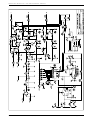
Alarms Card
Pag. 89
R.V.R. Elettronica S.r.l. (Bo)
Pag. 4
PJ250-NV Technical and Maintenance Manual
PRELIMINARY INSTRUCTIONS
AND WARRANTY INFORMATION
Please observe safety precautions when handling this unit.
equipment contains dangerous currents and high voltages.
This
This manual is written as a general guide for those having previous
knowledge and experience with this kind of equipment. It is not intended
to contain a complete statement of all safety warnings which should be
observed by personnel in using this or other elettronic equipment.
R.V.R. doesn't assume responsability for injury or damage resulting from
improper procedures or practices by untrained/unqualified personnel in
the handling of this unit.
Please observe all local codes and fire protection standards in the
operations of this unit.
CAUTION: always disconnect power before opening covers or removing any
part of this unit. Use appropriate grounding procedures to short out
capacitors and high voltage points before servicing.
Any damage to the goods must be reported to the carrier in writing on
the shipment receipt. Any discrepancy or damage discovered subsequent
to delivery, shall be reported to R.V.R. within five (5) days from its
receipt.
R.V.R. extends to the original end-user purchaser all original
manufacturers warranties which are transferable and all claims are to
be made directly to R.V.R. per indicated procedures.
All manufacturers warranties will be supported by R.V.R. to ensure
precise and speedy service where possible.
R.V.R. shall not be liable for any damage of whatsoever nature, arising
out of or in connection with the product or its use thereof.
R.V.R.'s warranty shall not include:
1)
2)
3)
4)
5)
Re-shipment of the unit to R.V.R. for repair purposes
Any unauthorized repair/modification
Incidental/consequential damages as a result of any defect
Nominal non-incidental defects
Re-shipment costs or insurance of the unit or replacement
units/parts
Warranty shall come into force from invoice date and for the period of
the manufactures warranty.
The warranty for a period of 12 months is referred to any R.V.R. product,
R.V.R. for
Elettronica
S.r.l.
(Bo)
Pag.
5
while
products
as transistors,
Mos-Fet and tubes of the final
stages
is applied the man fact re's arrant of these de ices
PJ250-NV Technical and Maintenance Manual
To claim your rights under this warranty:
a.
Contact the dealer or distributor where you prchased the unit.
Describe the problem and ask if he has an easy solution. Dealers
and Distributors are supplied with all the information about
problems that may occur and usually they can repair the unit quicker
than what the manufacturer could do. Very often installing errors
are discovered by dealers.
b.
If your dealer cannot help you, contact R.V.R. in Bologna and explain
the problem. If it is decided to return the unit to the factory,
R.V.R. will mail you a regular authorization with all the necessary
instructions to send back the goods.
c.
When you receive the authorization, you can return the unit. Pack
it carefully for the shipment, preferably using the original packing
and seal the package perfectly. The customer always assumes the
risks of loss (i.e., R.V.R. is never responsible for damage or loss),
until the package reaches R.V.R. premises. For this reason, we
suggest you to insure the goods for the whole value. Shipment must
be effected C.I.F. (PREPAID) to the address specified by R.V.R.'s
service manager on the authorization.
DO NOT RETURN UNITS WITHOUT OUR AUTHORIZATION AS THEY WILL BE
REFUSED.
Be sure to enclose a written technical report where mention all the
problems found and a copy of your original invoice establishing the
starting date of the warranty.
Replacement and warranty parts may be order from the following address.
Be sure to include the equipment model and serial number as well as part
description and part number.
R.V.R. Elettronica S.r.l.
Via del Fonditore, 2/2c
Zona Roveri
40138 Bologna - Italy
Telephone +39-51-6010506
Fax +39-51-6011104
- Broadcasting Equipment -
R.V.R. reserves the right to modify the design and specifications of the
equipment in this manual without previous notice.
R.V.R. Elettronica S.r.l. (Bo)
Pag. 6
PJ250-NV Technical and Maintenance Manual
WARNING!
The currents and voltages in this equipment are dangerous!
Personnel must at all times observe safety regulation!
This manual is intended as a general guide for trained and qualified
personnel who are aware of the dangers inherent in handling potentially
hazardous electrical and electronic circuits.
It is not intended to contain a complete statement of all safety
precautions which should be observed by personnel in using this or other
electronic equipment.
The installation, operation, maintenance and service of this equipment
involves risks both to personnel and equipment, and must be performed
only by qualified personnel exercising due care.
R.V.R. ELETTRONICA s.r.l. shall not be responsible for injury or damage
resulting from improper procedures or from the use of improperly trained
or inexperienced personnel performing such tasks.
During installation and operation of this equipment, local building codes
and fire protection standards must be observed.
WARNING!
Always disconnect power before opening covers,
doors, enclosures,
gates, panels or
shields.
Always use grounding sticks and short out high
voltage points before servicing. never make
internal
adjustments, perform
maintenance
or
service when alone or when fatigued.
Do not remove, short-circuit or tamper with interlock switches on
access covers, doors, enclosures, gates, panels or shields.
Keep away from live circuits, know your equipment and don’t take
chances.
WARNING!
In case of emergency ensure that power has been disconnected
R.V.R. Elettronica S.r.l. (Bo)
Pag. 7
PJ250-NV Technical and Maintenance Manual
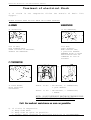
Treatment of electrical Shock
1) If victim is not responsive follow the A-B-C's of basic life
support.
PLACE VICTIM FLAT ON HIS BACK ON A HARD SURFACE
A AIRWAY
BBREATHING
IF UNCONSCIOUS,
OPEN AIRWAY
IF NOT BREATHING,
BEGIN ARTIFICIAL
BREATHING
LIFT UP NECK,
PUSH FOREHEAD BACK,
CLEAR OUT MOUTH IF NECESSARY,
OBSERVE FOR BREATHING.
TILT HEAD,
PINCH NOSTRILS,
MAKE AIRTIGHT SEAL,
4 QUICK FULL BREATHS.
REMEMBER MOUTH TO MOUTH
RESUSCITATION MUST BE
COMMENCED AS SOON AS
POSSIBLE.
C CIRCULATION
CHECK CAROTID PULSE
IF PULSE ABSENT,
BEGIN ARTIFICIAL
CIRCULATION
DEPRESS STERNUM 1 1/2" TO 2"
APPROX. 80 SEC. : ONE RESCUER, 15 COMPRESSIONS,
2 QUICK BREATHS.
APPROX. 60 SEC. : TWO RESCUERS, 5 COMPRESSIONS,
1 BREATH
NOTE: DONOTINTERRUPTRHYTHMOFCOMPRESSIONS
WHEN SECOND PERSON IS GIVING BREATH.
Call for medical assistance as soon as possible.
2) If
a.
b.
c.
R.V.R.
victim is responsive.
Keep them warm.
Keep them as quiet as possible.
Loosen their clothing (a reclining position is recommended).
Elettronica S.r.l. (Bo)
Pag. 8
PJ250-NV Technical and Maintenance Manual
FIRST-AID
Personnel engaged in the installation, operation,
maintenance or servicing of this equipment are
urged to become familiar with first-aid theory and
practices. The following information is not
intended to be a complete first-aid procedure, it
is brief and is only to be used as a reference. It
is the duty of all personnel using the equipment
to be prepared to give adequate Emergency First Aid
and thereby prevent avoidable loss of life.
Treatment of electrical Burns
1) Extensive burned and broken skin.
a. Cover area with clean sheet or cloth.
(Cleanest available cloth article).
b. Do not break blisters, remove tissue, remove adhered particles
of
clothing, or apply any salve or ointment.
c. Treat victim for shock as required.
d. Arrange transportation to a hospital as quickly as possible
e. If arms or legs are affected keep them elevated.
NOTE
If medical help will not be available within an hour and the victim
is conscious and not vomiting, give him a weak solution of salt and
soda: 1 level teaspoonful of salt and 1/2 level teaspoonful of baking
soda to each quart of water (neither hot or cold).
Allow victim to sip slowly about 4 ounces (half a glass) over a period
of 15 minutes.
Discontinue fluid if vomiting occurs (Do not give alcohol).
2) Less severe burns - (1st & 2nd degree)
a. Apply cool (not ice cold) compresses using the cleanest available
cloth article.
b. Do not break blisters, remove tissue, remove adhered
particles of clothing, or apply salve or ointment.
c. Apply clean dry dressing if necessary.
d. Treat victim for shock as required.
e. Arrange transportation to a hospital as quickly as possible.
f. If arms or legs are affected keep them elevated.
R.V.R. Elettronica S.r.l. (Bo)
Pag. 9
PJ250-NV Technical and Maintenance Manual
CHAPTER 1
GENERAL DESCRIPTION
1.1 EXTERNAL DESCRIPTION
The PJ250-NV is housed in a 3U 19" rack.
On the front panel the alarm indicators are placed in a central position,
the mains switch and the meter for the forward and reflected power.
On the rear panel the R.F. Input and R.F. Output connectors are located,
together with the interlock connectors, one of BNC type and one VDE
female, the main voltage input.
1.2 ELECTRICAL DESCRIPTION
The PJ250-NV is a power amplifier working on the 87.5-108 band with
an output power in excess of 250W and a drive level of about 20W.
This amplifier uses a RF module composed of four amplification stages
(MRF317 or SD1480), with a switching power supplies fixed with the RF
module on cooling ribs to obtain a high dissipation.
A built in low pass filter suppresses the harmonic contents below the
FCC and CCIR requirements.
A protection system protects the amplifier against thermal problems,
excessive input drive power and excessive SWR inside the amplifier or
along the feeder.
This system provides an automatic reset to initial conditions when the
problem ceases.
1.3 METERS AND INDICATORS
The forward and reflected power of the amplifier are read by the
analog multimeter (5 Fig.1) and selected by the selector (6 Fig.1) on
the front panel.
Various led (3 Fig.1) indicators indicate the alarm conditions caused
by thermal problems, excessive input drive power (4.Fig.1) and excessive
SWR.
A green indicator confirms the amplifier is operational (7 Fig.1).
1.4 PROTECTION CIRCUITS
The protection circuits put the amplifier in stand-by in the case
of a fault condition.
After 90 seconds the protection reactivates the amplifier if the fault
has disappeared.
If not, this process is repeated 4 times, at the end of which the amplifier
stays disabled for 15 min.; after 15 min, if the trouble persists, the
protection performs other four cycles and then disables the amplifier
indefinitely.
R.V.R. Elettronica S.r.l. (Bo)
Pag. 10
PJ250-NV Technical and Maintenance Manual
If during these cycles the anomaly disappears and the amplifier works
regularly for more than 15 min. the counting system is reset and the
original conditions established.
The protection acts for excessive SWR, over-temperature and overdrive.
It indicates the problem with warning lights and disables the pilot
exciter.
NOTE: The intervals described are nominal.
1.5 R.F. AMPLIFIERS
The amplifier comprises an RF broadband module with 50 Ohm input/
output impedance ("N" type connectors).
The output power of the module is approximately 250W across the frequency
range while the drive power is 20W; this output power is limited to 250W
to maintain a good level of reliability.
1.6 DEVICE SPECIFICATIONS
Refer to Table (A) for electrical specifications, and to Table (B)
for dimensional and environmental specifications.
R.V.R. Elettronica S.r.l. (Bo)
Pag. 11
PJ250-NV Technical and Maintenance Manual
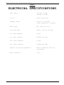
TABLEA
ELECTRICAL SPECIFICATIONS
Power Supply
100-130V, 50-60Hz
198-250V, 50-60Hz
Cooling
Forced ventilation
Frequency Range
from 87.5 to 108 MHz
(other frequencies on request)
Power Output
Max. 300W, Typ. 250 W
R.F. Drive Power
approx. 20 W for P out=250W
R.F. Input Impedance
50 Ohm
R.F. Input Connector
Standard "N" type
R.F. Output Impedance
50 Ohm
R.F. Output Connector
Standard "N" type
Harmonic and Spurious Suppression
meets or exceed FCC and CCIR
requirements
Power Consumption
570 W
R.V.R. Elettronica S.r.l. (Bo)
Pag. 12
PJ250-NV Technical and Maintenance Manual
TABLEB
MECHANICAL SPECIFICATIONS
Cabinet dimensions
439.00 mm (17.28") W
129.00 mm (5.080") H
341.50 mm (13.44") D
Panel dimensions
483.00 mm (19.00") W
132.50 mm (5.170") H
Operating temperature
from -10°C to 50°C
Humidity
95% max., non-condensing
Weight
20.5 Kg
R.V.R. Elettronica S.r.l. (Bo)
Pag. 13
PJ250-NV Technical and Maintenance Manual
CHAPTER 2
ELECTRICAL DESCRIPTION
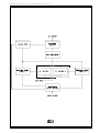
This section describes the overall working theory of PJ250-NV.
For ease of description the amplifier is subdivided into subassemblies
that will be discussed in detail below.
The block diagram is illustrated in Fig.3.
2.1 POWER SUPPLY
The power supply comprises two switching power supply (2-3 Photo
2) fitted to the cooling fins and its accessibles from the lower part
of the amplifier.
A mains transformer (2 Photo 1 and 1 Photo 1) has a selectable input for
voltages between 110 and 240 Volt and two outputs: A 31 Volt, B 18 Volt.
The output "A" drives the two switching units that generate the 28 Volt
needed by the R.F. modules.
Output "B" supplies the ALARMS CARD; inside this circuit a rectifying
and stabilization circuit provides the +15 Volt needed by the
electronics.
2.2 ALARMS CARD
This module (1 Photo 1) is composed of a board shielded by a metal
box mounted on the left side near the rear panel.
On this board, the electronics detect any system anomaly such as excessive
SWR, internal or antenna, over-temperature or over-drive.
This module will also, whenever possible, reset the system to its original
conditions, after a fault has occurred.
2.3 R.F. POWER
AMPLIFIER
The module (3 Photo 1) is placed in the upper right side of the
amplifier. This module is totally shielded and placed on a heat sink.
This circuit delivers 300W with 25-30W of drive and is supplied by a
dedicated power supply.
The quiescent parameters of each module are:
VDC=28V
I a=15A
P out=250 W
The active devices employed are BJT NPN (MRF317 or SD1480).
2.4 LOW PASS FILTER
This filter (4 Photo 1) is fitted in a metallic box mounted on the
heat sink on the right position.
R.V.R. Elettronica S.r.l. (Bo)
Pag. 14
PJ250-NV Technical and Maintenance Manual
Thanks to this low pass filter the harmonic suppression is more than
75 dBm.
2.5 DIRECTIONAL COUPLER
This circuit (5 Photo 1) is placed on the upper right side of the
amplifier and fitted on the rear panel.
This module makes the measurement of the forward and reflected power.
A BNC connector situated on the rear panel provides a power signal at
-40dB of the amplifier output power.
R.V.R. Elettronica S.r.l. (Bo)
Pag. 15
PJ250-NV Technical and Maintenance Manual
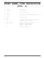
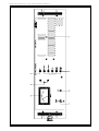
FRONT PANEL VIEW DESCRIPTION
(FIG. 1)
1
Power
On/Off Switch
2
Line
A.C. Line Indicator
3
Alarms
Leds indicating the PJ250-NV's alarms status
4
Grid
Air duct grid
5
Meter
Analog meter used to monitor the operating
parameters of the amplifier
6
Meter Selector
Selector to monitor parameters:
FWD PWR
Forward Power
RFL PWR
Reflected Power
7
On
"Power On" Indicator
R.V.R. Elettronica S.r.l. (Bo)
Pag. 16
PJ250-NV Technical and Maintenance Manual
FIG.1
R.V.R. Elettronica S.r.l. (Bo)
Pag. 17
PJ250-NV Technical and Maintenance Manual
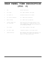
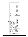
REAR PANEL VIEW DESCRIPTION
(FIG. 2)
1
Fan
Forced Ventilation
2
R.F. Input
R.F. Input Connector ("N" type)
3
D.C. Fuse 1-2
Protection Fuse for R.F. Module
4
A.C. Line for Exciter
A.C. Power Line for Exciter
5
Mains Voltage
A.C. Power Line for Amplifier
6
Voltage Changer and
A.C. Line Fuse
Fuse block and line voltage selector. Use a
small screwdriver to change the fuse or the
line voltage. Rotate the block and position it
for the desired voltage.
7
R.F. Output
R.F. Output Connector ("N" type)
8
R.F. Test -40dB
-40dB with respect to the Output Level
9
Alamrs/Interlock
BNC connector which permits the exciter to be
put in stand-by, in case of the amplifier
fault or in case of Ext.St.By.
R.V.R. Elettronica S.r.l. (Bo)
Pag. 18
PJ250-NV Technical and Maintenance Manual
FIG.2
R.V.R. Elettronica S.r.l. (Bo)
Pag. 19
PJ250-NV Technical and Maintenance Manual
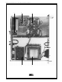
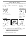
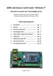
TOP VIEW DESCRIPTION (PHOTO 1)
1
....................
Alarms Card
2
....................
Transformer
3
....................
R.F. Power Amplifier
4
....................
Low Pass Filter
5
....................
Directional Coupler
R.V.R. Elettronica S.r.l. (Bo)
Pag. 20
PJ250-NV Technical and Maintenance Manual
5
4
3
1
2
PHOTO1
R.V.R. Elettronica S.r.l. (Bo)
Pag. 21
PJ250-NV Technical and Maintenance Manual
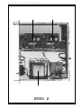
DOWN VIEW DESCRIPTION (PHOTO 2)
1
....................
Transformer
2
....................
Switching Power Supply 1
3
....................
Switching Power Supply 2
R.V.R. Elettronica S.r.l. (Bo)
Pag. 22
PJ250-NV Technical and Maintenance Manual
3
2
1
PHOTO2
R.V.R. Elettronica S.r.l. (Bo)
Pag. 23
PJ250-NV Technical and Maintenance Manual
FIG.3
R.V.R. Elettronica S.r.l. (Bo)
Pag. 24
PJ250-NV Technical and Maintenance Manual
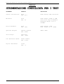
TABLEC
RECOMMENDED TEST EQUIPMENT
INSTRUMENT
MODEL
SPECIFICATION
Coaxial Load Resistor
Bird
Mod. 8173
Power Rating 300W continuous
Wattmeter
Bird
Mod. 43
Power Range: 100mW to 10KW
using Bird Plug-in-Elements
Frequency Range: 0.45 to
2300MHz
Plug-in-Elements
Bird
Mod. 500B
Power Rating: 500W
Freq. Range: 50 to 125MHz
Spectrum Analyzer
Hewlett Packard
Mod. 8591E
9KHz-1.8GHz
Oscilloscope
Tektronix
Mod. 7623A
F.M. Modulation Meter
Rohde Schwarz
Mod. F.A.M.
Digital Multimeter
Fluke
Mod. 73
R.V.R. Elettronica S.r.l. (Bo)
Pag. 25
PJ250-NV Technical and Maintenance Manual
CHAPTER 3
INSTALLATION OPERATIONS
3.1 UNPACKING
This chapter contains necessary information for the preliminary
checks and installation of the PJ250-NV.
3.2 UNPACKING
Unpack the amplifier and, before any other operation, check that
the amplifier isn’t damaged and that all controls on the front and rear
panel are in good condition.
3.3 INSTALLATION
1)
Check that the line voltage selector is correctly set for the local
supply.
If not, remove the cover on which the voltages are printed and rotate
it until the required value corresponds to the arrow, and reinsert
it.
Check also that the fuse (6 Fig.2) mounted inside the cover is
present and in order.
The current capacity of the the fuse are as follows:
220-240V - 8A
110-120V - 16A
2)
Place the mains switch in the OFF position (1 Fig.1).
3)
Insert the mains cable into the VDE socket (5 Fig.2).
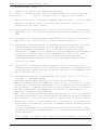
SETUP 1
4)
See SETUP 1, connect a dummy load with 250W power rating at 50 Ohm
to the R.F. output with a through wattmeter (BIRD mod.43 or similar).
5)
Switch on the mains switch and check the proper led is ON (7 Fig.1).
6)
Place the FWD/RFL PWR selector (6 Fig.1) in FWD position to measure
the forward power, and then in RFL position to measure the reflected
power.
R.V.R. Elettronica S.r.l. (Bo)
Pag. 26
PJ250-NV Technical and Maintenance Manual
Verify that both forward power and reflected power are zero.
7)
Connect the R.F.INPUT (2 Fig.2) to a suitable exciter (PTX30-UHT,
TEX20-NV etc.) able to deliver a power of between 20 and 30W.
8)
Connect the Alarms/Interlock Connector (9 Fig.2) to the BNC on the
rear panel of the exciter (Remote Control).
9)
Switch on the exciter with the output power set to the minimum value.
Tune the exciter to a middle band frequency (e.g. 98Mhz), wait for
the PLL to lock, then gradually raise the output power of the
exciter.
Verify the increase in the output power of the PJ250-NV.
Continue this operation until a 250W output value is obtained.
10)
Check the reading of the internal wattmeter of the PJ250-NV with
that of the external one (a discrepancy of about 10% is tolerable).
11)
Increase the drive power until the "Over Drive" led lights.
At this point, the lock condition should disable the amplifier and
exciter for about 90 sec, after which the amplifier will try to
restart.
If the drive power setting has not changed another lock condition
will occur, otherwise the amplifier will restart normally.
In the case of another lock condition, the protection circuit will
make 4 attempts at a restart.
Should this fail, the amplifier will wait for a longer period
(15min.), and make 4 more attempts.
Should this not be successful, the amplifier will remain disabled
indefinitely.
Should the fault not persist during one of these attempts, the
amplifier restarts normally and the protection’s counter will reset
automatically (after 15 min.).
NOTE: The intervals described are nominal.
R.V.R. Elettronica S.r.l. (Bo)
Pag. 27
PJ250-NV Technical and Maintenance Manual
CHAPTER4
MAINTENANCE
This chapter provides general maintenance
electrical adjustment procedures for the PJ250-NV
Maintenance is divided into categories dependent upon
the procedure and the test equipment required
maintenance.
information and
Amplifier.
the complexity of
to complete the
4.1 SAFETY CONSIDERATIONS
WARNING!
WARNING! WARNING!
WARNING!
WARNING! WARNING!
WARNING!
When the amplifier is operated with the top cover removed, hazardous
voltages are accessible on the AC line voltage selector and heavy currents
are accessible on the exposed terminals of the power supply filter
capacitor and power transistors mounted on the RF amplifier heat sink
assembly.
Use the insulated tuning tool provided for any adjustment and do not touch
any component within the amplifier when power is applied.
Ensure all primary power is disconnected from the amplifier before
attempting equipment maintenance.
FIRST LEVEL MAINTENANCE
4.2 ORDINARY MAINTENANCE
The only regular maintenance needed by the PJ250-NV, is the periodic
replacement of the blowers, and the cleaning of dust filters and any dust
accumulated inside the amplifier.
The time between overhauling of the blowers depends upon several
environmental factors, temperature, humidity, dust pollution etc.
Blowers should be checked every 6 months and replace if noisy.
They should be replaced any way after 18 months of service.
SECOND LEVEL MAINTENANCE
4.3 CARDS REPLACEMENT
This section contains useful information for card replacement.
WARNING! TO RE-INSTALL CARDS SIMPLY FOLLOW THE REVERSE PROCEDURE.
4.4 POWER SUPPLY REPLACEMENT
1) Open the bottom cover.
R.V.R. Elettronica S.r.l. (Bo)
Pag. 28
PJ250-NV Technical and Maintenance Manual
2)
Disconnect connector J1 on the switching card.
3)
Unscrew the two fixing screw of D1 and U1 devices, placed on the
heat-sink.
4)
Unscrew the fixing screws of the switching card.
5)
Remove the card.
NOTE: During replacement of broken devices it's necessary to pay
attention to device's pin position and insertion, to check that the
device's fixing screws aren't in short-circuit and to check that the
soldering is good and without impurities.
NOTE: Interpose between devices and heat-sink an electronic silicone
compound.
4.5 LOW PASS FILTER REPLACEMENT
1)
Open the top cover of the unit.
2)
Disconnect output SMA connector.
3)
Desolder input cable and the cover's box.
4)
Unscrew the four fixing screw of the Low Pass Filter.
5)
Remove the Low Pass Filter.
4.6 ALARMS CARD REPLACEMENT
1)
Open the top cover.
2)
Remove the screws fixing the card on the left side of the amplifier.
3)
Take note of the position of wires placed on the rear of the metal
box.
4)
Unsolder the wires placed on the rear of the metal box.
5)
Extract the Alarms card.
4.7 DIRECTIONAL COUPLER REPLACEMENT
1)
Open the top cover.
2)
Disconnect output SMA connector.
3)
Remove the fixing screws of the "N" type output connector (7 Fig.2).
R.V.R. Elettronica S.r.l. (Bo)
Pag. 29
PJ250-NV Technical and Maintenance Manual
4)
Remove the stop nut of the R.F. Test -40dB Connector (8 Fig.2).
5)
Take note of the position of the four wires going out of the
directional coupler and unsolder them.
5)
Extract the Directional Coupler.
4.8 TRANSFORMER REPLACEMENT
1)
Open the top and bottom covers.
2)
Take note of the position of the transformer’s wires connected to
the terminal block placed on the metal support of the transformer.
3)
Disconnect these wires from the terminal block.
4)
Remove the screws fixing the transformer on the left side of the
amplifier.
5)
Extract the transformer.
4.9 FAN REPLACEMENT
1)
Open the top and bottom covers.
2)
Desolder the two supply wires of the fan.
3)
Unscrew the fixing screws of the fan on the rear panel.
4)
Extract the fan.
R.V.R. Elettronica S.r.l. (Bo)
Pag. 30
PJ250-NV Technical and Maintenance Manual
CHAPTER 5
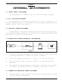
INTERNAL ADJUSTMENTS
5.1 POWER SUPPLY ADJUSTMENT
No adjustments are needed after this board has been changed.
5.2 R.F. SECTION ADJUSTMENT
No adjustment is required inside the R.F. section because it’s a
factory adjusted module; if calibration is necessary, please send the
module to your local distributor.
5.3 LOW-PASS FILTER ADJUSTMENT
No adjustment is required inside the Low-Pass Filter module because
it’s a factory adjusted module; if calibration is necessary, please send
the module to your local distributor.
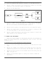
5.4 DIRECTIONAL COUPLER BALANCING (PWR MEASURE)
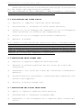
SETUP 2
1)
Connect a non inductive dummy load 50 Ohm P>250W to R.F. output with
a through wattmeter in series as shown in SETUP 2.
2)
Place the FWD/RFL PWR selector (6 Fig.1) to the RFL position.
3)
Set the exciter power to obtain 250W on the through external
wattmeter.
4)
Now, adjust variable capacitor C2 placed on the directional coupler
to obtain the minimum value on the meter, very near to zero.
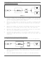
5.5 FORWARD AND REFLECTED POWER ADJUSTMENT
1)
Perform SETUP 2, and increase the amplifier’s output power to 250W
(on the external wattmeter).
R.V.R. Elettronica S.r.l. (Bo)
Pag. 31
PJ250-NV Technical and Maintenance Manual
2)
Place the FWD/RFL PWR selector (6 Fig.1) to the FWD position.
3)
Adjust trimmer R9 placed on the directional coupler for the same
reading on the PJ250-NV’s meter is obtained.
4)
Switch off the amplifier.
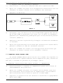
SETUP 3
5)
Connect a dummy load 25 Ohm 500W (or 2 dummy load 50 Ohm 250W in
parallel) with a through wattmeter (e.g. BIRD mod.43) in series,
set for the reading of reflected power (SETUP 3).
6)
Adjust the drive power to minimum and switch on the amplifier again.
7)
Adjust the output power of the exciter to obtain a reading of 25W
of reflected power on the external wattmeter.
8)
Adjust trimmer R6 placed on the directional coupler to obtain the
same reading on the PJ250-NV’s meter.
5.6 ALARMS CARD ADJUSTMENT
There are three trimmers on the Alarms card that are necessary to
adjust the alarm thresholds: over-temperature (R4), V.S.W.R. (R7) and
overdrive (R21).
A) CALIBRATION OF OVER-TEMPERATURE ALARM THRESHOLD
1)
Short-circuit the thermal switch placed on the RF section’s heat
sink.
2)
Adjust the trimmer, R4, placed on the Alarms card until the overtemperature protection is activated, and the TEMP. led lights up.
3)
Remove the short-circuit on the thermal switch and verify that the
TEMP. led goes out.
4)
Repeat this procedure again to verify the correct trimmer R4
adjustment.
R.V.R. Elettronica S.r.l. (Bo)
Pag. 32
PJ250-NV Technical and Maintenance Manual
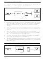
B) CALIBRATION OF V.S.W.R.
SETUP 4
1)
Connect a dummy load, 25 Ohm 500W (or two dummy loads 50 Ohm 250W
in parallel) with a by-pass wattmeter in series (e.g. BIRD mod.43)
set for reflected power reading (SETUP 4).
2)
Adjust the output power of the exciter to obtain a reading of 25W
of reflected power on the external wattmeter and the PJ250-NV’s
meter.
3)
Adjust the trimmer, R7, placed on the Alarms card until the S.W.R.
protection is activated, and the S.W.R. ANT. led lights up.
4)
Decrease the output power of the exciter and wait for the S.W.R.
led to go out (automatic protection cycle).
5)
Increase the output power of the exciter again over the S.W.R.
threshold of 25W, and verify, once again, that the S.W.R. ANT. led
lights up.
C) CALIBRATION OF OVER-DRIVE ALARM THRESHOLD
1)
Adjust the driver power to minimum and switch on the amplifier.
SETUP 5
2)
Connect a non inductive dummy load 50 Ohm P>250W to the R.F. output
with a through wattmeter (e.g. BIRD mod.43) in series as shown in
the SETUP 5.
3)
Place the FWD/RFL PWR selector (7 Fig.1) to the RFL position.
R.V.R. Elettronica S.r.l. (Bo)
Pag. 33
PJ250-NV Technical and Maintenance Manual
4)
Set the exciter power to obtain 250W on the through external
wattmeter and on the PJ250-NV’s meter.
5)
Increase the output power of the exciter again until a reading of
270W on the PJ250-NV’s meter is obtained.
6)
Adjust the trimmer, R21, placed on the Alarms card until the overdrive protection is activated, and the OVER DRIVE led lights up with
immediate shutdown of the amplifier.
7)
Decrease the drive power of the exciter and wait for the OVER DRIVE
led to go out.
8)
Increase the drive power of the exciter again over the overdrive
threshold of 270W, and verify, that the OVER DRIVE led lights up.
R.V.R. Elettronica S.r.l. (Bo)
Pag. 34
PJ250-NV Technical and Maintenance Manual
INDICE
Istruzioni Preliminari ed Informazioni di Garanzia
Pag. 37
Regole di Sicurezza
Pag. 39
CAPITOLO 1
Descrizione Generale
Specifiche Elettriche
Pag. 42
(Tabella A)
Pag. 44
Specifiche Dimensionali e Ambientali (Tabella B)
Pag. 45
CAPITOLO 2
Descrizione Elettrica
Pag. 46
Descrizione Vista Pannello Frontale
Pag. 48
Vista Pannello Frontale (Fig.1)
Pag. 49
Descrizione Vista Pannello Posteriore
Pag. 50
Vista Pannello Posteriore (Fig.2)
Pag. 51
Descrizione della Vista Superiore
Pag. 52
Vista Superiore (Fig.4)
Pag. 53
Descrizione della Vista Inferiore
Pag. 54
Vista Inferiore (Fig.5)
Pag. 55
Diagramma a Blocchi (Fig.3)
Pag. 56
Strumentazione consigliata per i Test (Table C)
Pag. 57
CAPITOLO 3
Procedure per l'installazione
Pag. 58
CAPITOLO 4
Manutenzione
Pag. 60
CAPITOLO 5
Operazioni di Taratura
Pag. 63
APPENDICE A
Schemi Elettrici, Lista Componenti e Piani di Montaggio
Pag. 67
Diagrammi delle Connessioni
Pag. 68
R.F. Power Amplifier Card
Pag. 69
Low Pass Filter
Pag. 74
Transformer Supply Section
Pag. 78
R.V.R. Elettronica S.r.l. (Bo)
Pag. 35
PJ250-NV Technical and Maintenance Manual
Switching Power Supply
Pag. 81
Directional Coupler Card
Pag. 85
Alarms Card
Pag. 89
R.V.R. Elettronica S.r.l. (Bo)
Pag. 36
PJ250-NV Technical and Maintenance Manual
ISTRUZIONI PRELIMINARI E
INFORMAZIONI DI GARANZIA
Prego osservare le necessarie precauzioni di sicurezza quando si usa
questa apparecchiatura. Questa macchina presenta al suo interno correnti
pericolose e alte tensioni.
Questo manuale è stato scritto per dare una guida generale per coloro
che hanno necessità di avere una conoscenza preliminare di questo tipo
di macchina. Esso non intende fornire una guida completa di tutte le
regole di sicurezza che dovrebbero essere osservate dal personale durante
l'uso di questa o altre apparecchiature elettroniche.
R.V.R. non assume la responsabilità per lesioni o danni causati da
procedure errate o da un uso improprio da parte di personale non
addestrato o non qualificato all'uso di questa unità.
Prego osservare le norme locali e regole antincendio durante l'uso di
questa macchina.
ATTENZIONE:
disconnettere sempre l'alimentazione prima di aprire
coperchi o di rimuovere qualsiasi parte di questa
apparecchiatura. Usare appropriate procedure di messa a
terra per scaricare i condensatori e i punti di alta
tensione prima di qualsiasi manutenzione.
Qualsiasi danno all'apparecchiatura deve essere segnalato al corriere
e scritto sulla ricevuta di spedizione. Qualsiasi differenza o danno
scoperto dopo la consegna, dovrà essere riferito all'R.V.R. entro cinque
(5) giorni dalla consegna.
R.V.R. estende al cliente utente finale tutte le garanzie originali di
fabbricazione che sono trasferibili e tutti i reclami devono essere fatti
direttamente all'R.V.R. secondo procedure prestabilite.
Tutte le garnzie di fabbricazione saranno trattenute dall'R.V.R. per
assicurare un assistenza precisa e veloce dove possibile.
R.V.R. non sarà responsabile per qualsiasi danno di qualsiasi nautra,
a causa o in relazione all'uso del prodotto.
La garanzia R.V.R. non include:
1)
2)
3)
4)
5)
Spedizione della macchina all'R.V.R. per la riparazione
Qualsiasi modifica o riparazione non autorizzata
Danni incidentali/causati non dovuti a difetti della macchina
Difetti nominali non incidentali
Costi di spedizione o di assicurazione della macchina o
sostituzione di parti o unità
R.V.R. Elettronica S.r.l. (Bo)
Pag. 37
PJ250-NV Technical and Maintenance Manual
La garanzia entrerà in vigore dalla data di fattura per il periodo di
garanzia di costruzione.
La garanzia di 12 mesi è riferita a qualsiasi prodotto R.V.R., mentre
su prodotti quali transistors, Mos-Fet e valvole per finali vale la
garanzia della casa costruttrice di tali dispositivi.
Per reclamare i propri diritti con questa garanzia:
a.
Contattare il rivenditore o il distributore dove avete acquistato
la macchina. Descrivere il problema e chiedre se è in grado di
fornirvi una facile soluzione. Rivenditori e Distributori sono in
grado di fornire tutte le informazioni relative ai problemi che
possono presentarsi e normalmente possono riparare la macchina più
velocemente di quello che potrebbe fare la casa costruttrice. Molto
spesso errori di installazione vengono scoperti dai rivenditori.
b.
Se il vostro rivenditore non può aiutarvi, contattare l'R.V.R. in
Bologna e spiegare il problema. Se viene stabilito di rispedire la
macchina alla fabbrica, l'R.V.R. vi spedirà una regolare autorizzazione
con tutte le necessarie istruzioni per la restituzione della merce.
c.
Quando avete ricevuto l'autorizzazione, potete restituire la
macchina. Imballarla con molta attenzione per la spedizione,
preferibilmente usando l'imballo originale e sigillare l'imballo
perfettamente. Il cliente assume sempre il rischio di perdita (es.,
l'R.V.R. non è mai responsabile per danni o perdita), finchè
l'imballo non raggiunge la sede dell'R.V.R.. Per questo motivo, vi
consigliamo di assicurare la merce per il valore intero. La
spedizione deve essere effettuta C.I.F. (PREPAID) all'indirizzo
specificato dall'R.V.R. sull'autorizzazione.
NON RESTITUIRE LA MACCHINA SENZA LA NOSTRA AUTORIZZAZIONE IN QUANTO
POTREBBE ESSERE RIFIUTATA.
Assicurarsi di allegare una diagnosi tecnica sritta dove sono elencati
tutti i problemi riscontrati e una copia della vostra fattura originale
che mostra la data di partenza della garanzia.
La sostituzione di parti in garanzia può essere richiesta al seguente
indirizzo. Assicurarsi di allegare il modello della macchina e il numero
di serie come pure la descrizione della parte e il suo numero di codice.
R.V.R. Elettronica S.r.l.
Via del Fonditore, 2/2c
Zona Roveri
40138 Bologna - Italy
- Broadcasting Equipment -
L'R.V.R. si riserva il diritto di apportare modifiche al progetto e alle
specifiche della macchina in questo manuale senza alcun preavviso.
R.V.R. Elettronica S.r.l. (Bo)
Pag. 38
PJ250-NV Technical and Maintenance Manual
ATTENZIONE!
Le correnti e le tensioni presenti in questo dispositivo sono
pericolose, il personale deve osservare sempre le norme di
sicurezza.
Questo manuale rappresenta una guida generale per il personale addestrato
e qualificato che è consapevole dei pericoli inerenti al trattamento
potenzialmente rischioso dei circuiti elettrici ed elettronici.
Esso non si propone di contenere una relazione completa di tutte le
precauzioni di sicurezza che devono essere osservate dal personale che
utilizza questo o altri dispositivi.
L'installazione, il funzionamento, la manutenzione e l'impiego di questo
dispositivo implica rischi sia per il personale che per il dispositivo
stesso, il quale deve essere utilizzato solo da personale qualificato
esercitando la dovuta attenzione.
La R.V.R. ELETTRONICA s.r.l. non sarà responsabile per lesioni o danni
risultanti da procedure improprie o dall'uso di personale inesperto o
non correttamente addestrato all'adempimento di tali mansioni.
Durante l'installazione e il funzionamento di questo dispositivo, devono
essere osservate le regole antincendio e i codici di costruzione locali.
ATTENZIONE!
Disconnettere sempre l'alimentazione prima di aprire i coperchi, i
pannelli o le protezioni. Usare sempre strumenti isolati prima
dell'utilizzo. Non eseguire mai regolazioni interne, operazioni di
manutenzione o di servizio quando si è soli o quando si è stanchi.
Non rimuovere cortocircuiti o blocchi con interruttori interbloccanti
su coperchi d'accesso, chiusure, pannelli e protezioni.
Tenersi lontano dai circuiti sotto tensione, imparare a conoscere il
dispositivo e non prendere rischi.
ATTENZIONE!
In caso di emergenza assicurarsi che l'alimentazione sia stata
disconnessa.
R.V.R. Elettronica S.r.l. (Bo)
Pag. 39
PJ250-NV Technical and Maintenance Manual
Trattamento degli shock elettrici
1) Se la vittima ha perso conoscenza seguire i principi di primo soccorso
riportati nei punti A-B-C.
POSIZIONARE LA VITTIMA SDRAIATA SULLA SCHIENA SU UNA SUPERFICIE RIGIDA
A VIE AEREE
BRESPIRAZIONE
SE NON COSCIENTE,
APRIRE LE VIE AEREE
SE NON RESPIRA,
INIZIARE LA RESPIRAZIONE
ARTIFICIALE
SOLLEVARE IL COLLO
SPINGERE INDIETRO LA FRONTE
APRIRE LA BOCCA SE NECESSARIO
CONTROLLARE LA RESPIRAZIONE
INCLINARE LA TESTA
CHIUDERE LE NARICI
FARE ADERIRE LA BOCCA A
QUELLA DELLA VITTIMA
PRATICARE 4 RESPIRAZIONI
VELOCI
RICORDARSI DI INIZIARE
IMMEDIATAMENTE LA
RESPIRAZIONE
C CIRCOLAZIONE
CONTROLLARE IL BATTITO CARDIACO
IN ASSENZA DI BATTITO,
INIZIARE IL MASSAGGIO
CARDIACO
COMPRIMERE LO STERNO DA 1 1/2" A 2"
APPROS. 80 SEC. : 1 SOCCORRITORE, 15 COMPRESSIONI,
2 RESPIRAZIONI VELOCI.
APPROS. 60 SEC. : 2 SOCCORRITORI, 5 COMPRESSIONI,
1 RESPIRAZIONE.
N.B.: NON INTERROMPERE IL RITMO DI COMPRESSIONE QUANDO LA SECONDA
PERSONA STA ESEGUENDO LA RESPIRAZIONE ARTIFICIALE.
Chiamareunmedicoilprimapossibile.
2) Se
a.
b.
c.
la vittima è cosciente:
coprire la vittima con una coperta.
tranquillizzare la vittima.
slacciare gli abiti (sistemare la vittima in posizione coricata).
R.V.R. Elettronica S.r.l. (Bo)
Pag. 40
PJ250-NV Technical and Maintenance Manual
PRIMO-SOCCORSO
Il personale impegnato nell’installazione, nel
funzionamento, nella manutenzione o assistenza di
questo dispositivo ha la necessità di avere
familiarità con la teoria e le pratiche di primo
soccorso.
La relazione seguente non rappresenta una guida
completa delle procedure di primo soccorso, ma è
solo un riassunto che deve essere usato come
riferimento.
E’ compito di tutto il personale che usa questo
dispositivo essere pronti a prestare un adeguato
soccorso e perciò prevenire evitabili decessi.
TRATTAMENTO DELLE USTIONI ELETTRICHE
1)
Vaste ustioni e tagli della pelle.
a.
b.
Coprire l’area con un lenzuolo o un panno pulito.
Non rompere le vesciche, rimuovere il tessuto, rimuovere le
particelle di vestito che si sono attaccate alla pelle,
applicare una pomata adatta.
Trattare la vittima come richiede il tipo di shock.
Trasportare la vittima in ospedale il più velocemente possibile.
Se braccia o gambe sono state colpite, tenerle sollevate.
c.
d.
e.
NOTA BENE
Se l’aiuto medico non è disponibile prima di un’ora e la vittima è
cosciente e non ha sforzi di vomito, somministrargli una soluzione
liquida di sale e soda: 1 cucchiaino pieno di sale e mezzo cucchiaino
di bicarbonato di sodio ogni 250 ml d’acqua (ne’ caldo ne’ freddo).
Permettere alla vittima di sorseggiare lentamente per circa 4 volte
(1/2 bicchiere) per un periodo di 15 minuti.
Interrompere se si verificano sforzi di vomito.(Non dare alcool).
2)
a.
Ustioni meno gravi (1° e 2° grado).
Applicare compresse di garza fredde(non ghiacciate) usando un panno
il più possibile pulito.
R.V.R.
Elettronica
(Bo)
b.
Non
rompereS.r.l.
le vesciche,
rimuovere il tessuto, rimuoverePag.
le 41
ti ll di
tit
h
i
tt
t
ll
ll
li
PJ250-NV Technical and Maintenance Manual
CAPITOLO 1
DESCRIZIONE GENERALE
1.1 DESCRIZIONE ESTERNA
Il PJ250-NV è realizzato in un contenitore rack 19" 3U.
Sul pannello frontale sono presenti: gli indicatori dei vari allarmi
posti in posizione centrale, l’interruttore generale di potenza e lo
strumento analogico per la misura della potenza diretta e riflessa.
Sul pannello posteriore sono presenti: i connettori RF input e RF output,
i connettori per i comandi di protezione, uno di tipo BNC e una VDE femmina
per l’alimentazione di apparati esterni (es. eccitatore) e l’ingresso
della tensione di rete.
1.2 DESCRIZIONE ELETTRICA
Il PJ250-NV è un amplificatore di potenza sulla banda 87.5-108 MHz
(è disponibile anche la versione O.I.R.T. 66-75 MHz) con una potenza in
uscita di oltre 250W continui su tutta la banda, e con un livello di
pilotaggio di circa 20W.
Questo amplificatore dispone di un modulo R.F. formato da quattro stadi
di amplificazione (MRF317 o SD1480), alimentati da due Power Supply di
tipo "Switching", montati come pure il modulo RF su alette di
raffreddamento per ottenere una efficace dissipazione termica.
Inoltre è presente un filtro passa-basso per contenere l’emissione dei
segnali armonici entro i livelli previsti dalle norme FCC e CCIR.
E’ presente anche un sistema di protezioni che salvaguardano i
dispositivi contro malfunzionamenti dovuti alla temperatura, all’eccesso
di pilotaggio e ad un eccesso di onde stazionarie, con avvisatori ottici
di intervento ed interdizione del trasmettitore pilota in caso di
intervento. Questo sistema di protezioni possiede inoltre il ripristino
automatico delle condizioni iniziali, in caso di cessata anomalia.
1.3 MISURATORI E INDICATORI
La potenza diretta e la potenza riflessa dell’amplificatore sono
verificabili tramite lo strumento analogico (5 Fig.1) e sono selezionabili
tramite il selettore FWD/RFL PWR (6 Fig.1), entrambi presenti sul
pannello frontale. Sono presenti vari led indicatori di allarme (3 Fig.1)
che segnalano condizioni di malfunzionamento e causate rispettivamente
da temperatura eccessiva, eccesso di pilotaggio ed eccesso di onde
stazionarie. Sempre sul pannello frontale è presente un led verde che
indica la messa in funzione della macchina (7 Fig.1).
1.4 CIRCUITI DI PROTEZIONE
I circuiti di protezione disattivano l’apparecchiatura in caso di
R.V.R. Elettronica S.r.l. (Bo)
Pag. 42
PJ250-NV Technical and Maintenance Manual
anomalia .
A distanza di circa 90 secondi la protezione riabilita l’apparecchiatura
salvo la persistenza dell’anomalia.
In tal caso la procedura si ripete quattro volte al termine della quale
l’apparato rimane interdetto per 15 min., scaduti i quali se l’anomalia
dovesse persistere si ha un nuovo ciclo di 4 interventi che una volta
conclusi determinano il definitivo arresto dell’apparecchiatura.
Se invece nel corso di questi cicli l’anomalia scompare e quindi
l’amplificatore funziona regolarmente per più di 15 min., il sistema di
conteggio del circuito di protezioni viene azzerato e si ripristinano
le condizioni iniziali.
I circuiti di protezione intervengono per un eccesso di VSWR, di
temperatura e pilotaggio con avvisatori ottici di intervento e con
conseguente interdizione del trasmettitore pilota.
1.5 AMPLIFICATORE RF
Il modulo R.F. è a larga banda ed ha impedenza d’ingresso e d’uscita
di 50 Ohm (connettore tipo N).
La potenza d’uscita max è di circa 300W su tutta la banda mentre la potenza
d’ingresso è di circa 25W, tale potenza viene volutamente limitata a 250W
per mantenere un buon livello di affidabilità.
1.6 SPECIFICHE DELL’APPARATO
Fare riferimento alla Tabella (A) per la caratteristiche elettriche
e alla Tabella (B) per quelle dimensionali e ambientali.
R.V.R. Elettronica S.r.l. (Bo)
Pag. 43
PJ250-NV Technical and Maintenance Manual
TABELLAA
SPECIFICHE ELETTRICHE
Alimentazione A.C.
100-130V, 50-60Hz
198-250V, 50-60Hz
Raffreddamento
Ventilazione Forzata
Frequenza di Lavoro
da 87.5 a 108 MHz
(altre frequenze su richiesta)
Potenza d'Uscita
Max. 300W, Tip. 250 W
Potenza di Pilotaggio R.F.
circa 20 W per P out=250W
Impedenza d'Ingresso R.F.
50 Ohm
Connettore Ingresso R.F.
Standard tipo "N"
Impedenza d'Uscita R.F.
50 Ohm
Connettore Uscita R.F.
Standard tipo "N"
Soppressione delle Armoniche
conforme o superiore alle
specifiche FCC e CCIR
Potenza Assorbita
570 W
R.V.R. Elettronica S.r.l. (Bo)
Pag. 44
PJ250-NV Technical and Maintenance Manual
TABELLAB
SPECIFICHE DIMENSIONALI E AMBIENTALI
Dimensioni del Cabinet
439.00 mm (17.28") L
129.00 mm (5.080") A
341.50 mm (13.44") P
Dimensioni del Pannello
483.00 mm (19.00") L
132.50 mm (5.170") A
Temperatura di Lavoro
da -10°C a 50°C
Umidità
Massimo 95%, senza condensa
Peso
20.5 Kg
R.V.R. Elettronica S.r.l. (Bo)
Pag. 45
PJ250-NV Technical and Maintenance Manual
CAPITOLO 2
DESCRIZIONE ELETTRICA
2.1 INTRODUZIONE
Questa sezione descrive in maniera complessiva la teoria di
funzionamento del PJ250-NV.
Per comodità descrittiva l’apparato è stato suddiviso in sottoinsiemi
che saranno discussi in maniera approfondita di seguito.
Il diagramma a blocchi dell’apparecchiatura è rappresentato in Fig.3.
2.2 POWER SUPPLY
Il Power Supply è composto da due alimetatori di tipo "Swtiching"
(2-3 Foto 2), fissati su un’aletta di raffreddamento, accessibile dalla
parte inferiore della macchina.
E’ costituito da un trasformatore di rete con ingresso selezionabile tra
110 e 240V AC e due uscite: A 31V B 18V.
L’uscita A serve per alimentare i due alimetatori Switching.
L’uscita B viene utilizzata dalla scheda protezioni (Alarms Card),
all’interno della quale un alimentatore stabilizzato provvede alla
realizzazione della tensione di +15V DC necessaria al funzionamento dei
propri circuiti.
2.3 ALARMS CARD
Questo modulo è costituito da una scheda (1 Foto 1) contenuta in
un contenitore metallico fissato sul fianco sinistro vicino al pannello
posteriore della macchina.
I circuiti contenuti all’interno di questa scheda sono in grado di
rivelare la presenza di anomalie del sistema, come: un eccesso di
pilotaggio, presenza di onde stazionarie interne o in antenna, un eccesso
di temperatura.
Questo modulo provvede anche al ripristino, qualora sia possibile, delle
condizioni iniziali.
2.4 R.F. POWER AMPLIFIER
Il modulo "RF Power Amplifier" (3 Foto 1), fissato su un dissipatore
termico, è posizionato nella parte superiore destra della macchina.
Questo modulo, capace di erogare fino a 300W con pilotaggio di 25-30 W.
I parametri tipici a regime del modulo sono:
VDC=28V
I a=15A
P out=250W
I dispositivi utilizzati sono BJT NPN (MRF 317 o SD1480).
R.V.R. Elettronica S.r.l. (Bo)
Pag. 46
PJ250-NV Technical and Maintenance Manual
2.5 LOW PASS FILTER
Questo dispositivo (4 Foto
contenitore metallico fissato sul
Grazie alla presenza di questo
riduzione dei segnali armonici di
1) è contenuto all’interno di un
dissipatore del modulo R.F..
filtro passa-basso si ottiene una
oltre 75 dB.
2.6 ACCOPPIATORE DIREZIONALE
Questa scheda (5 Foto 1) è situata nella parte superiore destra ed
è fissata al pannello posteriore.
Questo dispositivo effettua la misura della potenza diretta e riflessa
in uscita.
L'accoppiatore direzionale è dotato di un connettore di tipo BNC (8 Fig.2)
per il prelievo a livello -40dB del segnale disponibile in uscita
dell'amplificatore.
R.V.R. Elettronica S.r.l. (Bo)
Pag. 47
PJ250-NV Technical and Maintenance Manual
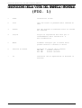
DESCRIZIONE DELLA VISTA DEL PANNELLO FRONTALE
(FIG. 1)
1
Power
Interruttore On/Off
2
Line
Spia che indica la presenza della tensione di
rete
3
Alarms
Led che indicano un eventuale stato di allarme
del PJ250-NV
4
Griglia
Griglia di aspirazione dell'aria per il
raffreddamento della sezione R.F. e
dell'alimentatore
5
Meter
Strumento analogico per la misura della
potenza diretta e riflessa in uscita
6
Selttore di Misura
Selettore di lettura della potenza:
FWD PWR
Potenza Diretta
RFL PWR
Potenza Riflessa
7
On
Indicatore led di segnalazione di macchina in
funzione
R.V.R. Elettronica S.r.l. (Bo)
Pag. 48
PJ250-NV Technical and Maintenance Manual
FIG.1
R.V.R. Elettronica S.r.l. (Bo)
Pag. 49
PJ250-NV Technical and Maintenance Manual
DESCRIZIONEDELLAVISTADELPANNELLOPOSTERIORE(FIG.
2)
1
Griglia
Griglia di protezione per la fuori-uscita
dell'aria di reffreddamento
2
R.F. Input
Connettore d'Ingresso R.F., tipo "N"
3
D.C. Fuse 1-2
Fusibili di Protezione per il Modulo R.F.
4
A.C. Line for Exciter
Spina di alimentazione per l'alimentazione
dell'eccitatore pilota
5
Mains Voltage
Spina per la tensione di rete
dell'amplificatore
6
Blocco Fusibile di Linea e
Cambia Tensione
Blocco fusibile di rete e cambiatensione.
Usare un piccolo cacciavite per cambiare
fusibile o tensione. Girare il blocco e
posizionarlo sulla tensione di funzionamento
desiderato.
7
R.F. Output
Connettore d'Uscita R.F., tipo "N"
8
R.F. Test -40dB
Connettore BNC per Test di Misura
9
Alarms/Interlock
Connettori BNC che permettono di porre
l'eccittatore in stand-by, nel caso in cui
l'amplificatore entri in una situazione di
allarme. Tutto ciò viene fatto portando a
massa il centrale dei connettori BNC di
Alarms/Interlock
R.V.R. Elettronica S.r.l. (Bo)
Pag. 50
PJ250-NV Technical and Maintenance Manual
FIG.2
R.V.R. Elettronica S.r.l. (Bo)
Pag. 51
PJ250-NV Technical and Maintenance Manual
DESCRIZIONE DELLA VISTA DALL'ALTO (FOTO 1)
1
....................
Alarms Card
2
....................
Trasformatore
3
....................
R.F. Power Amplifier
4
....................
Filtro Passa Basso
5
....................
Accoppiatore Direzionale
R.V.R. Elettronica S.r.l. (Bo)
Pag. 52
PJ250-NV Technical and Maintenance Manual
5
4
3
1
2
FOTO 1
R.V.R. Elettronica S.r.l. (Bo)
Pag. 53
PJ250-NV Technical and Maintenance Manual
DESCRIZIONE DELLA VISTA INFERIORE (FOTO 2)
1
....................
Trasformatore
2
....................
Switching Power Supply 1
3
....................
Switching Power Supply 2
R.V.R. Elettronica S.r.l. (Bo)
Pag. 54
PJ250-NV Technical and Maintenance Manual
3
2
1
FOTO 2
R.V.R. Elettronica S.r.l. (Bo)
Pag. 55
PJ250-NV Technical and Maintenance Manual
FIG.3
R.V.R. Elettronica S.r.l. (Bo)
Pag. 56
PJ250-NV Technical and Maintenance Manual
TABELLAC
STRUMENTAZIONE CONSIGLIATA PER I TEST
STRUMENTO
MODELLO
SPECIFICHE
Coaxial Load Resistor
Bird
Mod. 8173
Power Rating 300W continuous
Wattmeter
Bird
Mod. 43
Power Range: 100mW to 10KW
using Bird Plug-in-Elements
Frequency Range: 0.45 to
2300MHz
Plug-in-Elements
Bird
Mod. 500B
Power Rating: 500W
Freq. Range: 50 to 125MHz
Spectrum Analyzer
Hewlett Packard
Mod. 8591E
9KHz-1.8GHz
Oscilloscope
Tektronix
Mod. 7623A
F.M. Modulation Meter
Rohde Schwarz
Mod. F.A.M.
Digital Multimeter
Fluke
Mod. 73
R.V.R. Elettronica S.r.l. (Bo)
Pag. 57
PJ250-NV Technical and Maintenance Manual
CAPITOLO 3
OPERAZIONI PER
L’INSTALLAZIONE
3.1 INTRODUZIONE
Questo capitolo contiene le informazioni necessarie
l’installazione ed il controllo preliminare del PJ250-NV.
per
3.2 DISIMBALLAGGIO
Togliere dall’imballo l’apparecchiatura e prima di iniziare
qualsiasi operazione, controllare che l’apparato non abbia subito danni
durante il trasporto, e che quindi tutti i comandi presenti sul pannello
anteriore e posteriore siano perfettamente funzionanti.
3.3 INSTALLAZIONE
1)
Verificare sul pannello posteriore che il selettore della tensione
di rete (6 Fig.1) sia posizionato sul giusto valore: eventualmente
con un cacciavite sollevare il cappuccio su cui sono stampati i
valori di tensione e ruotarlo fino a che il valore che interessa
corrisponda con la freccetta e quindi reinserirlo.
Verificare inoltre la presenza e l'integrità del fusibile contenuto
nel cappuccio stesso.
I valori in Ampère di tale fusibile sono qui di seguito riassunti:
220-240V - 8A
110-130V - 16A
2)
Controllare che l’interruttore dell’alimentazione (1 Fig.1) sia
nella posizione OFF.
3)
Inserire il cavo dell’alimentazione nella presa VDE (5 Fig.2).
SETUP 1
4)
Collegare un carico fittizio 50 Ohm P>250W sull’uscita R.F.
(7 Fig.2) con in serie un wattmetro passante (es. BIRD mod.43) come
R.V.R. Elettronica S.r.l. (Bo)
Pag. 58
PJ250-NV Technical and Maintenance Manual
mostrato nel SETUP 1.
5)
Inserire la spina alla presa di corrente.
6)
Porre l’interruttore dell’alimentazione in posizione ON
verificare
che il relativo led (7 Fig.1) sia acceso.
e
7)
Selezionare con il selettore FWD/RFL PWR (6 Fig.1) la misura FWD
(potenza diretta) e poi la misura RFL (potenza riflessa) e
constatare che siano nulle.
8)
Collegare all’ingresso R.F. (2 Fig.2) un eccitatore (es. PTX30-UHT,
TEX20-NV, etc.) in grado di erogare una potenza compresa tra 20 e
30W.
9)
Collegare il connettore BNC Alarms/Interlock (9 Fig.2) al relativo
BNC posto sul retro dell’eccitatore (Remote Control).
10)
Accendere l’eccitatore con la potenza d’uscita regolata al minimo.
Sintonizzare l’eccitatore su una frequenza di centro banda
(es.98.00 MHz), attendere che il PLL dell’eccitatore abbia
effettuato l’aggancio di frequenza, quindi aumentare gradualmente
la potenza d’uscita dell’eccitatore stesso, indi verificare il
conseguente aumento della potenza d’uscita del PJ250-NV.
Continuare questa operazione fino a raggiungere una potenza
d’uscita di 250W.
11)
Verificare l’esattezza della potenza d’uscita indicata dallo
strumento del PJ250-NV con il wattmetro passante, considerando che
la misura può essere affetta da errore dovuto allo strumento fino
ad un massimo del 10%.
12)
Incrementare ancora la potenza di pilotaggio fino a che non si
accende il led OVER DRIVE.
A questo punto deve avvenire il blocco della macchina e
dell’eccitatore per un tempo di circa 90 sec., trascorsi i quali
la macchina tenterà di ripartire: se la regolazione della potenza
di pilotaggio è rimasta invariata, si avrà un nuovo blocco, se invece
si sarà provveduto ad abbassare la potenza di pilotaggio, la
macchina ripartirà regolarmente.
Nel caso di ulteriore blocco della macchina, il ciclo si ripeterà
fino ad un massimo di quattro dopodiché la macchina eseguirà un pausa
più lunga di circa 15 minuti, quindi ripeterà altri quattro cicli,
terminati i quali e persistendo tali condizioni, la macchina si
blocca definitivamente e tramite il comando remote interdice anche
l’eccitatore.
In caso l’anomalia non sia più presente durante uno di questi cicli,
la macchina riparte regolarmente e il contatore delle protezioni
viene azzerato.
N.B. I tempi di risposta della macchina sono puramente indicativi.
R.V.R. Elettronica S.r.l. (Bo)
Pag. 59
PJ250-NV Technical and Maintenance Manual
CAPITOLO 4
MANUTENZIONE
4.1 INTRODUZIONE
Questa capitolo fornisce le informazioni generali per la
manutenzione dell’amplificatore PJ250-NV.
La manutenzione si divide in due categorie dipendenti dalla
complessità delle procedure e dalle attrezzature necessarie per una
completa manutenzione.
4.2 NORME DI SICUREZZA
ATTENZIONE ATTENZIONE ATTENZIONE ATTENZIONE ATTENZIONE ATTENZIONE
Quando l’amplificatore è in funzione, e il coperchio superiore è
stato rimosso, sono presenti pericolose tensioni sul selettore di
tensione di linea AC e alte correnti sui terminali del filtro capacitivo
del power supply e sui transistors di potenza sul dissipatore
dell’amplificatore RF.
Usare degli utensili isolati per qualsiasi tipo di taratura e non toccare
alcun componente all’interno dell’amplificatore quando l’apparecchiatura
è alimentata.
Assicurarsi di disconnettere l’alimentazione di rete dell’amplificatore
prima di effettuare qualsiasi operazione di manutenzione.
PRIMO LIVELLO DI MANUTENZIONE
4.3 MANUTENZIONE ORDINARIA
L’unica manutenzione di cui necessita il PJ250-NV è la periodica
sostituzione dei ventilatori e relativa pulizia da tracce di polvere
eventualmente accumulate al suo interno.
Tale periodicità è funzione delle condizioni di funzionamento della
macchina, temperatura ambiente, livello di polvere nell’aria, umidità.
Si consiglia di effettuare un controllo preventivo ad intervalli di 6
mesi e di sostituire le ventole che presentassero rumore o attriti
eccessivi, e comunque di provvedere alla loro sostituzione non oltre i
18 mesi.
SECONDO LIVELLO DI MANUTENZIONE
4.4 SOSTITUZIONE SCHEDE
R.V.R. Elettronica S.r.l. (Bo)
Pag. 60
PJ250-NV Technical and Maintenance Manual
Questa sezione contiene le informazioni pratiche per la sostituzione
dei vari moduli dell’amplificatore PJ250-NV.
N.B. PER RIMONTARE LE PARTI COMPONENTI L’AMPLIFICATORE E’ SUFFICIENTE
ESEGUIRE LE OPERAZIONI NELLA SEQUENZA INVERSA.
4.5 SOSTITUZIONE DEL POWER SUPPLY
1)
Togliere il coperchio inferiore della macchina.
2)
Disconnettere il connettore J1 sulla scheda Switching.
3)
Svitare le viti di fissaggio dei componenti U1 e D1 al dissipatore
(fare attenzione all'isolatore del componente D1).
4)
Svitare le viti di fissaggio della scheda alimentatore.
5)
Estrarre la scheda.
N.B.: Durante la sostituzione del dispositivo rotto, è necessario porre
molta attenzione alla posizione e all'inserimento dei pin del
dispositivo, controllare che le viti di fissaggio del dispositivo non
siano in corto-circuito e controllare che la saldatura sia buona e senza
impurità. Inoltre, interporre tra il dispositivo U1 e il dissipatore un
composto di silicone per componenti elettronici.
4.6 SOSTITUZIONE DELLA ALARMS CARD
1)
Togliere il coperchio superiore della macchina.
2)
Annotare la corretta posizione dei fili posti sul fianco del
contenitore.
3)
Dissaldare i fili posti sul fianco del contenitore (condensatori
passanti).
4)
Svitare le due viti che fissano il contenitore della scheda sul lato
sinistro dall'apparato.
5)
Estrarre la scatola Alarms card.
4.7 SOSTITUZIONE DEL FILTRO PASSA BASSO
1)
Aprire il coperchio superiore della macchina.
2)
Disconnettere il connettore d'ingresso SMA.
3)
Dissaldare il cavo d'ingresso ed il coperchio della scatola del
filtro.
R.V.R. Elettronica S.r.l. (Bo)
Pag. 61
PJ250-NV Technical and Maintenance Manual
4)
5)
Svitare le viti che fissano il filtro al dissipatore della sezione
R.F..
Estrarre il filtro.
4.8 SOSTITUZIONE DELL’ACCOPPIATORE DIREZIONALE
1)
Togliere il coperchio superiore della macchina.
2)
Disconnettere il connettore d'ingresso SMA.
3)
Svitare le viti che fissano il connettore "N" d’uscita al retro
dell'amplificatore.
4)
Svitare il dado che fissa il connettore "BNC" R.F. Test -40db al
retro dell'apparato.
5)
Annotare la posizione dei quattro fili in uscita dall’accoppiatore
direzionale e dissaldarli.
6)
Estrarre l’accoppiatore direzionale.
4.9 SOSTITUZIONE DEL TRASFORMATORE
1)
Togliere i coperchi superiore ed inferiore della macchina.
2)
Annotare la posizione dei fili del trasformatore entranti nella
morsettiera fissata sul supporto metallico del trasformatore
stesso.
3)
Scollegare questi fili dalla morsettiera.
4)
Svitare le viti che fissano il trasformatore al fianco sinistro
dell'apparato.
5)
Estrarre il trasformatore dalla macchina.
4.10 SOSTITUZIONE DELLA VENTOLA
1)
Togliere il coperchio superiore ed inferiore della macchina.
2)
Disconnettere i fili dai faston posizionati sulla parte inferiore
della ventole (in alcuni casi tali fili potrebbero non avere i faston
ed essere saldati, occorre pertanto dissaldarli).
3)
Svitare le viti che fissano la ventola al retro dell'apparato.
4)
Estrarre le ventole.
R.V.R. Elettronica S.r.l. (Bo)
Pag. 62
PJ250-NV Technical and Maintenance Manual
CAPITOLO 5
TARATURA
5.1 TARATURA DEL POWER SUPPLY
Nessuna taratura è necessaria dopo la sostituzione di questa scheda.
5.2 TARATURA DELLO STADIO R.F.
Nessuna taratura è normalmente necessaria su questo stadio, nel caso
in cui siano necessarie tarature sullo stadio R.F., inviare la macchina
alla casa costruttrice.
5.3 TARATURA DEL FILTRO PASSA-BASSO
Il filtro passa-basso viene fornito già tarato dalla fabbrica, nel
caso in cui siano necessarie tarature sul filtro passa-basso, inviare
la macchina alla casa costruttrice.
5.4 BILANCIAMENTO DELL’ACCOPPIATORE DIREZIONALE DI USCITA (MISURA PWR)
SETUP 2
1)
Collegare all’uscita R.F. un carico resistivo 50 Ohm P>250W con in
serie un wattmetro passante come mostrato nel SETUP 2.
2)
Posizionare il selettore FWD/RFL PWR nella posizione RFL.
3)
Regolare l’eccitatore per ottenere una lettura di 250W sul wattmetro
passante esterno.
4)
Ora, regolare il compensatore C2 posizionato all’interno
dell’accoppiatore direzionale per ottenere la minima lettura sullo
strumento, molto vicino allo zero.
5.5 TARATURA DELLA POTENZA DIRETTA E RIFLESSA
1)
Realizzare il SETUP 2, e mandare in potenza l’amplificatore fino
R.V.R. Elettronica S.r.l. (Bo)
Pag. 63
PJ250-NV Technical and Maintenance Manual
2)
a leggere 250W sul wattmetro esterno.
Posizionare il selettore FWD/RFL PWR nella posizione FWD.
3)
Agire sul trimmer R9 posto sull’accoppiatore direzionale fino ad
ottenere la stessa lettura sullo strumento del PJ250-NV.
4)
Spegnere le macchine.
SETUP 3
5)
Collegare, ora, un carico fittizio 25 Ohm 500W (oppure due carichi
da 50 Ohm 250W in parallelo tra loro) con in serie un wattmetro
passante (es. BIRD mod.43) predisposto per la lettura della potenza
riflessa (SETUP 3).
6)
Regolare al minimo la potenza di pilotaggio e alimentare nuovamente
il sistema.
7)
Agire sulla potenza dell’eccitatore per ottenere una lettura della
potenza riflessa di 25W sul wattmetro esterno.
8)
Agire sul trimmer R6 situato sull’accoppiatore direzionale per
ottenere la stessa lettura sullo strumento interno.
5.6 TARATURA DELLA ALARMS CARD
La scheda ALARMS CARD è provvista di tre trimmer che regolano le
soglie d’intervento rispettivamente: della temperatura (R4), eccesso di
ROS (R7) e eccesso di potenza di pilotaggio (R21).
A) TARATURA DELLA PROTEZIONE CONTRO ECCESSI DI TEMPERATURA
1)
Cortocircuitare il sensore di temperatura posto sull’aletta di
raffreddamento del piano R.F..
2)
Agire sul trimmer R4 posto all’interno della Alarms card fino
all’intervento della protezione di temperatura, riscontrabile
dall’accensione della relativa spia di allarme TEMP..
3)
Togliere il cortocircuito sul sensore e verificare lo spegnimento
della spia TEMP.
R.V.R. Elettronica S.r.l. (Bo)
Pag. 64
PJ250-NV Technical and Maintenance Manual
4)
Ripetere
correttezza
l’intera sequenza di operazioni e
della taratura del trimmer R4.
verificare
la
B) TARATURA DELLA PROTEZIONE DI R.O.S.
SETUP 4
1)
Collegare, ora, un carico fittizio 25 Ohm 500W (oppure due carichi
da 50 Ohm 250W in parallelo tra loro) con in serie un wattmetro
passante predisposto per la lettura della potenza riflessa
(SETUP 4).
2)
Agire sulla potenza dell’eccitatore per ottenere una lettura della
potenza riflessa di 25W sul wattmetro esterno e sullo strumento del
PJ250-NV.
3)
Agire sul trimmer R7 fino a far intervenire la protezione di R.O.S.,
riscontrabile dall’accensione della relativa spia di allarme S.W.R.
ANT., con conseguente blocco della macchina.
4)
Diminuire la potenza dell’eccitatore e attendere che tale spia
S.W.R. ANT. si spenga (riciclo automatico).
5)
Aumentare nuovamente la potenza dell’eccitatore oltre la soglia dei
25W di potenza riflessa e constatare, ancora una volta, l’accensione
della spia S.W.R.
C) TARATURA DELLA PROTEZIONE CONTRO ECCESSI DI POTENZA DI PILOTAGGIO
1)
Regolare al minimo la potenza di pilotaggio e alimentare il sistema.
SETUP 5
R.V.R. Elettronica S.r.l. (Bo)
Pag. 65
PJ250-NV Technical and Maintenance Manual
2) Posizionare il selettore FWD/RFL PWR nella posizione RFL.
3)
Collegare all’uscita R.F. un carico resistivo 50 Ohm 250W con in
serie un wattmetro passante (es. BIRD mod.43) come mostrato nel
SETUP 5.
4)
Regolare l’eccitatore per ottenere una lettura di 250W sul wattmetro
passante esterno e sullo strumento interno del PJ250-NV.
5)
Aumentare ancora la potenza dell’eccitatore fino ad avere una
potenza in uscita dal PJ250-NV di 270W.
6)
Agire sul trimmer R21 posto all’interno della scheda Alarms card
fino a far intervenire la protezione di sovrapilotaggio, riscontrabile
dall’accensione della relativa spia OVER DRIVE con conseguente
blocco della macchina.
7)
Diminuire la potenza di pilotaggio dell’eccitatore e attendere lo
spegnimento della spia di allarme OVER DRIVE.
8)
Aumentare nuovamente la potenza di pilotaggio e verificare
l’intervento della protezione in corrispondenza di un valore di
270W.
R.V.R. Elettronica S.r.l. (Bo)
Pag. 66
PJ250-NV Technical and Maintenance Manual
APPENDIX A
CIRCUIT DIAGRAMS, LAYOUTS AND BILLS OF MATERIAL
This section contains circuit diagrams, layouts and bills of
material of the modules which composing the equipment. For more
information about each module see as reference Section 2.
APPENDICE A
CIRCUITIELETTRICI,PIANIDIMONTAGGIOELISTECOMPONENTI
Questo capitolo contiene gli schemi elettrici, i piani di montaggio
e le liste componenti delle schede che compongono la macchina. Per
ulteriori informazioni riguardanti le singole schede vedere come
riferimento il Capitolo 2.
R.V.R. Elettronica S.r.l. (Bo)
Pag. 67
PJ250-NV Technical and Maintenance Manual
WIRING DIAGRAM
R.V.R. Elettronica S.r.l. (Bo)
Pag. 68
PJ250-NV Technical and Maintenance Manual
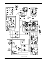
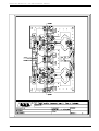
R.F. POWER AMPLIFIER
1
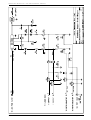
CircuitDiagram
Pag. 70
2
Bill of Materials
Pag. 71
3
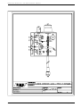
CoponentLayout
Pag. 73
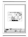
R.F. POWER AMPLIFIER
1
Schema Elettrico
Pag. 70
2
Lista dei Componenti
Pag. 71
3
Piano di Montaggio
Pag. 73
R.V.R. Elettronica S.r.l. (Bo)
Pag. 69
PJ250-NV Technical and Maintenance Manual
R.V.R. Elettronica S.r.l. (Bo)
Pag. 70
PJ250-NV Technical and Maintenance Manual
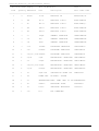
R.F. Power Amplifier
Bill Of Materials
Page 1
Item
Quantity Reference
Part
Description
Part Order Code
____________________________________________________________________________________________________
1
6
R5,R8,R10, 2.2*
R14,R16,R18
RESISTOR 1/2W 5%
RSC1/2JH02,2
2
2
R9,R17
RESISTOR 1/4W 5%
RSC1/4JH0012
3
6
R4,R7,R11, 12*
R13,R15,R19
RESISTOR 1/2W 5%
RSC1/2JH0012
4
2
R6,R12
39#
RESISTOR 2W
RSC002JH0039
5
2
R20,R21
47#
RESISTOR 2W
RSC002JH0047
6
2
C4,C22
12pF
CERAMIC CAPACITOR NP0
CKM120BJ600C
7
2
C17,C34
68pFHQ
HIGHT Q CAPACITOR
CHQ680AJ500
8
4
C3,C6,C21,
C23
150pFHQ
HIGHT Q CAPACITOR
CHQ151AJ500
9
2
C8,C25
470pFHQ
HIGHT Q CAPACITOR
CHQ471AJ500
10
8
C10,C14,
1nFUNELCO
C18,C19,C27,
C31,C35,C36
SILVER MICA CAPACITOR
CSM102XK351
11
8
C1,C2,C11, 4n7
C15,C20,C21,
C28,C32
CERAMIC CAPACITOR
CKM472BK600P
12
2
C7,C24
CERAMIC CAPACITOR
CKM473BK600P
13
4
C9,C13,C26, 0.1µF
C30
CERAMIC CAPACITOR
CKM104BK600P
14
4
C12,C16,
C29,C33
100µF
ELECTROLYTIC CAPACITOR
CEA107BM350
15
4
L7,L8,L9,
L12
0µ22
RF CHOKE
IMP0U22A
16
4
L4,L6,L10,
L14
VK
RF CHOKE
IMPVK00A
17
4
L3,L5,L11,
L13
L43RVR
4 SP DIA 3
18
4
CV1,CV2,
CV3,CV4
RG179-75
CAOX CABLE RG179 75Ohm
CAVRG17975
19
4
TR1,TR2,
TR3,TR4
RG316-25
CAOX CABLE RG316 25Ohm
CAVRG31625
20
4
Q1,Q2,Q3,Q4 MRF317
RF POWER TRANSISTOR
TRNMRF317
21
10
ST1,ST2,
STRIP LINE
ST3,ST4,ST5,
ST6,ST7,ST8,
ST9,ST10,
STRIP LINE
12
47nF
R.V.R. Elettronica S.r.l. (Bo)
Pag. 71
PJ250-NV Technical and Maintenance Manual
R.F. Power Amplifier
Bill Of Materials
Page 2
Item
Quantity Reference
Part
Description
Part Order Code
____________________________________________________________________________________________________
22
4
ST11,ST12,
ST13,ST14,
ST15,ST16
R.V.R. Elettronica S.r.l. (Bo)
STRIP LINE
STRIP LINE
Pag. 72
PJ250-NV Technical and Maintenance Manual
R.V.R. Elettronica S.r.l. (Bo)
Pag. 73
PJ250-NV Technical and Maintenance Manual
LOW PASS FILTER
1
CircuitDiagram
Pag. 75
2
Bill of Materials
Pag. 76
3
CoponentLayout
Pag. 77
LOW PASS FILTER
1
Schema Elettrico
Pag. 75
2
Lista dei Componenti
Pag. 76
3
Piano di Montaggio
Pag. 77
R.V.R. Elettronica S.r.l. (Bo)
Pag. 74
PJ250-NV Technical and Maintenance Manual
R.V.R. Elettronica S.r.l. (Bo)
Pag. 75
PJ250-NV Technical and Maintenance Manual
Low Pass Filter
Bill Of Materials
Page 1
Item
Quantity Reference
Part
Description
Part Order Code
____________________________________________________________________________________________________
1
2
C19,C33
4p7FHQ
HIGHT Q CAPACITOR
CHQ4,7AJ500
2
1
C18
10pFHQ
HIGHT Q CAPACITOR
CHQ100AJ500
3
8
C16,C17,
C20,C21,
C22,C23,
C24,C25
27pFUNELCO
SILVER MICA CAPACITOR
CSM270XK351
4
1
C1
1nFPAS
CERAMIC THROUGH CAPAC.
CDP102XK500
5
2
L5,L6
L28RVR1.5
2SP D8 RAME ARG. 1.5mm
BFS15000208
6
3
L7,L8,L9
L410RVR2
4SP D10 RAME ARG. 2.0mm BFS20000410
7
1
J1
SMAF
CONN. SMA F TELAIO
R.V.R. Elettronica S.r.l. (Bo)
CNTSMAF
Pag. 76
PJ250-NV Technical and Maintenance Manual
R.V.R. Elettronica S.r.l. (Bo)
Pag. 77
PJ250-NV Technical and Maintenance Manual
TRANSFORMER SUPPLY SECTION
1
CircuitDiagram
Pag. 79
2
Bill of Materials
Pag. 80
TRANSFORMER SUPPLY SECTION
1
Schema Elettrico
Pag. 79
2
Lista dei Componenti
Pag. 80
R.V.R. Elettronica S.r.l. (Bo)
Pag. 78
PJ250-NV Technical and Maintenance Manual
R.V.R. Elettronica S.r.l. (Bo)
Pag. 79
PJ250-NV Technical and Maintenance Manual
Transformer Supply Section
Bill Of Materials
Page 1
Item
Quantity Reference
Part
Description
Part Order Code
____________________________________________________________________________________________________
1
2
R1,R2
2K2 1%
RESISTOR 1/4W 1%
RSC1/4FK02,2
2
1
F1
F6.3A
FAST FUSIBILE
FUS5X20RP6.3
3
2
F3,F4
FB20A
FAST FUSIBILE
FUS6X30RP20
4
1
CT1
FILCT
FILTRO VDE CON C. TENS. CNTVDEMPCT
5
1
VDE1
VDE FPAN.
VDE FEMMINA DA PANNELLO CNTVDEFP
6
1
SW2
1V 2P P 15A DEVIAT. 1V 2P PAN. 15A
DEV1V1015
7
1
D1
KBPC2502
DIODE BRIDGE 25A
PNRKBPC2502
8
1
LP1
SPIA
R07-220V
SPIA AL NEON 220V ROSSA SPIA07RO220
9
2
D2,D3
LED-R5
RED LED DIODE
LEDRO05
10
1
TR1
TRPJ250NV
TRASFORMATORE PJ250-NV
TRFPJ250NV
11
1
FAN1
VTL4650N
VENTOLA 120x120 220VAC
VTL4650N
R.V.R. Elettronica S.r.l. (Bo)
Pag. 80
PJ250-NV Technical and Maintenance Manual
SWITCHING POWER SUPPLY
1
CircuitDiagram
Pag. 82
2
Bill of Materials
Pag. 83
3
CoponentLayout
Pag. 84
SWITCHING POWER SUPPLY
1
Schema Elettrico
Pag. 82
2
Lista dei Componenti
Pag. 83
3
Piano di Montaggio
Pag. 84
R.V.R. Elettronica S.r.l. (Bo)
Pag. 81
PJ250-NV Technical and Maintenance Manual
R.V.R. Elettronica S.r.l. (Bo)
Pag. 82
PJ250-NV Technical and Maintenance Manual
Switching Power Supply
Bill Of Materials
Page 1
Item
Quantity Reference
Part
Description
Part Order Code
____________________________________________________________________________________________________
1
2
R5,R6
0.22$
RESISTOR 5W
RAF005JH0,22
2
1
R8
1K 1%
RESISTOR 1/4W 1%
RSM1/4FK0001
3
1
R7
4K7 1%
RESISTOR 1/4W 1%
RSM1/4FK04,7
4
1
R4
18K 1%
RESISTOR 1/4W 1%
RSM1/4FK0018
5
1
R3
22K 1%
RESISTOR 1/4W 1%
RSM1/4FK0022
6
1
C7
330pF
CERAMIC CAPACITOR
CKM331BK600P
7
1
C9
2n2
CERAMIC CAPACITOR
CKM222BK600P
8
1
C8
22nF
CERAMIC CAPACITOR
CKM223BK600P
9
1
C10
100nFP
POLIESTER CAPACITOR
CPE104DK101
10
1
C15
220nFP
POLIESTER CAPACITOR
CPE224DK101
11
3
C16,C17,C18 680nFP
POLIESTER CAPACITOR
CPE684DK101
12
2
C3,C4
10µF
ELECTROLYTIC CAPACITOR
CEA106AM350
13
1
C5
100µF
ELECTROLYTIC CAPACITOR
CEA107BM350
14
3
C12,C13,C14 220µF
ELECTROLYTIC CAPACITOR
CEA227BM350
15
2
C1,C2
2200µF
ELECTROLYTIC CAPACITOR
CEA228CM350
16
1
L1
40µH 10A
TOROIDAL RF CHOKE 10A
IMP40U10A
17
1
L2
POWER IND.
RF BINOC. CHOCKE
18
1
J1
MORSKB10PPO MORS. LUMB. FEM. CS 10P MORSKB10PPO
19
1
D1
STPS10
RECTIFIER DIODE
DIDSTPS10
20
1
U1
L4970
SWITCHING REGULATOR
CILL4970
21
1
C11
N.C.
NOT CONNECTED
R.V.R. Elettronica S.r.l. (Bo)
Pag. 83
PJ250-NV Technical and Maintenance Manual
R.V.R. Elettronica S.r.l. (Bo)
Pag. 84
PJ250-NV Technical and Maintenance Manual
DIRECTIONAL COUPLER
1
CircuitDiagram
Pag. 86
2
Bill of Materials
Pag. 87
3
CoponentLayout
Pag. 88
DIRECTIONAL COUPLER
1
Schema Elettrico
Pag. 86
2
Lista dei Componenti
Pag. 87
3
Piano di Montaggio
Pag. 88
R.V.R. Elettronica S.r.l. (Bo)
Pag. 85
PJ250-NV Technical and Maintenance Manual
R.V.R. Elettronica S.r.l. (Bo)
Pag. 86
PJ250-NV Technical and Maintenance Manual
Directional Coupler
Bill Of Materials
Page 1
Item
Quantity Reference
Part
Description
Part Order Code
____________________________________________________________________________________________________
1
3
R4,R7,R12
47 1%
RESISTOR 1/4W 1%
RSM1/4FH0047
2
2
R1,R2
47#
RESISTOR 2W
RSC002JH0047
3
2
R10,R11
100
RESISTOR 1/4W 5%
RSC1/4JH0100
4
1
R3
1K*
RESISTOR 1/2W 5%
RSC1/2JK0001
5
2
R5,R8
12K 1%
RESISTOR 1/4W 1%
RSM1/4FK0012
6
2
R13,R14
15K
RESISTOR 1/4W 5%
RSC1/4JK0015
7
2
R15,R16
47K5 1%
RESISTOR 1/4W 1%
RSM1/4FK47.5
8
2
R6,R9
T22K
TRIMMER REG. VERT. 10mm RVTD10VK0022
9
1
C1
2p2
CERAMIC CAPACITOR NP0
CKM2,2BJ600C
10
1
C2
T2p22F
TRIMMER CAPACITOR
CVC2,22CK600
11
6
C3,C4,C5,
C6,C7,C8
1nFPAS
CERAMIC THROUGH CAPAC.
CDP102XK500
12
1
CN3
BNC TELAIO
CONN. BNC A TELAIO
CNTBNCFPV
13
1
CN2
SMAM
CONN. SMA M PER RG303
14
1
CN1
N CONNECTOR CONN. N A TELAIO
CNTNFPFL
15
3
D1,D2B,D2A
BAT83
HOT CARRIER DIODE
DHCBAT83
16
1
TR1
WIDE-BAND
TRF
WIDE-BAND TRANSFORMER
TRFWIDEBAND
R.V.R. Elettronica S.r.l. (Bo)
Pag. 87
PJ250-NV Technical and Maintenance Manual
R.V.R. Elettronica S.r.l. (Bo)
Pag. 88
PJ250-NV Technical and Maintenance Manual
ALARMS CARD
1
CircuitDiagram
Pag. 90
2
Bill of Materials
Pag. 91
3
CoponentLayout
Pag. 93
ALARMS CARD
1
Schema Elettrico
Pag. 90
2
Lista dei Componenti
Pag. 91
3
Piano di Montaggio
Pag. 93
R.V.R. Elettronica S.r.l. (Bo)
Pag. 89
PJ250-NV Technical and Maintenance Manual
R.V.R. Elettronica S.r.l. (Bo)
Pag. 90
PJ250-NV Technical and Maintenance Manual
Alarms Card
Bill Of Materials
Page 1
Item
Quantity Reference
Part
Description
Part Order Code
____________________________________________________________________________________________________
1
3
R8,R10,R22
10 1%
RESISTOR 1/4W 1%
RSM1/4FH0010
2
1
R9
47 1%
RESISTOR 1/4W 1%
RSM1/4FH0047
3
1
R2
100 1%
RESISTOR 1/4W 1%
RSM1/4FH0100
4
1
R1
680*
RESISTOR 1/2W 5%
RSC1/2JH0680
5
2
R5,R6
1K 1%
RESISTOR 1/4W 1%
RSM1/4FK0001
6
3
R30,R31,R32 1K2 1%
RESISTOR 1/4W 1%
RSM1/4FK01,2
7
3
R3,R41,R54
2K2 1%
RESISTOR 1/4W 1%
RSC1/4FK02,2
8
9
R39,R40,
10K 1%
R42,R44,R45,
R47,R49,R50,
R51
RESISTOR 1/4W 1%
RSM1/4FK0010
9
9
R16,R20,
22K 1%
R24,R28,R33,
R35,R36,R37,
R53
RESISTOR 1/4W 1%
RSM1/4FK0022
10
4
R43,R46,
R48,R52
47K 1%
RESISTOR 1/4W 1%
RSM1/4FK0047
11
2
R18,R25
82K 1%
RESISTOR 1/4W 1%
RSM1/4FK0082
12
10
R11,R12,
100K 1%
R13,R14,R15,
R17,R19,R23,
R26,R27
RESISTOR 1/4W 1%
RSM1/4FH0100
13
2
R34,R38
220K 1%
RESISTOR 1/4W 1%
RSM1/4FK0220
14
3
R4,R7,R21
T22K
TRIM. REG. VERT. 10mm
RVTD10VK0022
15
3
C3,C5,C7
4n7
CERAMIC CAPACITOR
CKM472BK600P
16
4
C2,C4,C11,
C14
47nF
CERAMIC CAPACITOR
CKM473BK600P
17
2
C18,C19
0.47µF
POLIESTER CAPACITOR
CPE474EK101
18
1
C22
0.47µFT
TANTALIUM CAPACITOR
CET474AM350
19
2
C23,C24
1µF
ELECTROLYTIC CAPACITOR
CEA105AM630
20
1
C10
2.2µFT
TANTALIUM CAPACITOR
CET225AM350
21
4
C12,C13,
C16,C21
4.7µF
ELECTROLYTIC CAPACITOR
CEA475AM350
22
1
C17
10µF
ELECTROLYTIC CAPACITOR
CEA106AM350
23
1
C1
10µFT
TANTALIUM CAPACITOR
CET106AM350
R.V.R. Elettronica S.r.l. (Bo)
Pag. 91
PJ250-NV Technical and Maintenance Manual
Alarms Card
Bill Of Materials
Page 2
Item
Quantity Reference
Part
Description
Part Order Code
____________________________________________________________________________________________________
24
1
C20
22µF
ELECTROLYTIC CAPACITOR
CEA226BM350
25
2
C6,C8
33µF
ELECTROLYTIC CAPACITOR
CEA336BM350
26
1
C15
100µF
ELECTROLYTIC CAPACITOR
CEA107BM350
27
1
L1
220µH
RF CHOKE
IMP220UA
28
1
RELE’1
RY12W-K
RELAY 2 VIE 12V TAKAM.
RLDRY12W-K
29
18
D1,D2,D3,
1N4148
D4,D8,D9,
D10,D11,D12,
D13,D14,D15,
D17,D18,D19,
D21,D22,D23
SILICON DIODE
DIS1N4148
30
1
D16
1N4001
SILICON DIODE 50V
DIS1N4001
31
1
W1
WL04
DIODE BRIDGE 1.5A
PNRWL04
32
1
D20
Z6V8
ZENER DIODE 6.8V 0.4W
DIZ6V80W4
33
1
IC5
7815
POS. STABILIZER 1A
CIL7815P
34
2
Q2,Q3
BC237
NPN TRANSISTOR
TRNBC237
35
1
Q4
BD140
PNP TRANSISTOR
TRNBD140
36
1
IC2
NE555
TIMER
CIL555
37
2
IC3,IC4
4040
CMOS DIVIDER
CID4040
38
1
IC1
LM3900
NORTON QUAD AMP.
CILLM3900
R.V.R. Elettronica S.r.l. (Bo)
Pag. 92
PJ250-NV Technical and Maintenance Manual
R.V.R. Elettronica S.r.l. (Bo)
Pag. 93
PJ250-NV Technical and Maintenance Manual
© Copyright 1993
First Edition - December ’95
Created By D’Alessio D. & Morotti M.
R.V.R. Elettronica S.r.l. (Bo)
Via del Fonditore 2/2c - 40138 - Bologna (Italy)
National: Phone 051/601.05.06 r.a. Fax 051/601.11.04
International: Phone +39 51-601.05.06 Fax +39 51-601.11.04
Printed and bound in Italy. All rights reserved. No part of this manual may be
reproduced or utilized in any form or by any means, electronic or mechanical,
including photocopying, recording, or by any information storage and retrieval
system, without permission in writing from the publisher.
Tutti i diritti sono riservati. Stampato in Italia. Nessuna parte di questo libro
può essere riprodotta, memorizzata in stistemi di archivio, o trasmessa in
quasiasi forma o mezzo, elttronico, meccanico, fotocopia, registrazione o altri
senza la preventiva autorizzazione scritta dell'editore.
R.V.R. Elettronica S.r.l. (Bo)
Pag. 94
PJ250
APPENDIX
Description
Power Supply
Appendix
RVR Code
PSSW2812B
Rev. 0.1 - 03/09/02
Vers. Page
0.1
4
i
PJ250
Pagina lasciata intenzionalmente in bianco
ii
Rev. 0.1 - 03/09/02
Appendix
PJ250
Technical Appendix
Rev. 0.1 - 03/09/02
PSSW2812B - 1 / 4
KRA2
1
2
JP1
+
1000/50
+
C14
C16
+
1000/50
+
C15
C12
+
1
C9
1
R22
1K80
C2
4n7UF
2.5%
C1
CP.1uF
2
C13
C10
C3
R19
2K2
22K
R1
R27
820R
CP.1uF
1
2
CP.1uF
1
2
1000/50
1
1
2
1000/50
C20
165KHZ
C21
2
R26
CD10KPF
1
10M
10K
R18
C5
+
CT1/35
DZ1
13V/1W
CD.1uF
C26
2
100/25
+
C32
C11
C4
+
1
2
3
4
5
6
7
8
C29
4.7uF
D3
8
7
6
5
CD1KPF
C30
VB
HO
CS
VS
47R
R4
4K7
R20
16
15
14
13
12
11
10
9
PWR
CD.1UF
VCC
CD.1UF
C17
CD1KPF/100
C18
CM.22uF
VREF
VCC
OUT
VC
PWRGND
ILMREF
GND
ILS.D.
UC3823
IR2125
VCC
IN
ERR
GND
U1
11DQ06
INV.
N.I.
E/A OUT
CLK
RT
CT
RAMP
S.START
U2
10K
R16
1
2
3
4
VCC
PWR
CM.1UF
470R/5W
R17
VIN
1
2
CP.1uF
1
2
CP.1uF
1
2
1000/50
1
2
R5
DZ3
C19
VREF
15V/1W
R3
10R
IRFZ44
Q1
D1
11DQ06
5k6
R12
C8
CD.1UF
4R7
R11
SHDW
CD1KPF/100
D2
MBR1660
1K
R2
C31
R6
10R/2W
1
2
10R/2W
1
2
1
2
1
2
DZ2
3V3/0.5
R10
1K
R15
MIA10UH
L1
4N26
VCC
T2812
C7
+
6
C24
IS1
\\JACK\
MANUALI\APPENDIX\PJ250\PS2812.DSN
)LOH&DUWHOOD
R13
C6
1.0
$XWRUL]]D]LRQH
5HYLVLRQH
&RGLFH
1RPH3DUWH
GL
1
6L]H
KRA5
1
2
3
4
5
JP5
A3
PSSW2812B
POWER SUPPLY 2812B 10A
/
3DJLQD
1
2P
JP3
SHDW
'DWDTuesday, September 03, 2002&RGLFH3URJHWWR
560K
BC237
R8
680R
CD.1UF
220/35
+
C28
R21
Q2
1K
10R
560R
4N26
R23
4
2
1RPH3&LQ5HWH
5
1
R1/10W
GRIPTECH - REV.: BERTI J.
3V3/0.5
DZ4
3K3
R7
+
R25
R22/5W
R14
R9
PJ250
R24
560K
VIN
+
C25
EKR220/63
EKR220/63
BL02
$XWRUH
+
C23
N.C.
F2
F1
1RPH3URJHWWR
IS2
EKR220/63
EKR220/63
1
2
6
C22
1
2
Rev. 0.1 - 03/09/02
2
5
2
2 / 4 - PSSW2812B
4
1
2
2
1
1
PJ250
Technical Appendix
PJ250
POWER SUPPLY
Bill Of Materials
Page1
Item
Q.ty
Reference
Part
_____________________________________________________________________________________________________
1
2
3
1
5
1
C1
C2,C3,C9,C10,C11
C4
4n7UF
CP.1uF
CM.1UF
4
5
1
5
C5
C6,C8,C17,C19,C26
CT1/35
CD.1uF
6
7
8
4
5
1
C7,C23,C24,C25
C12,C13,C14,C15,C16
C18
EKR220/63
1000/50
CM.22uF
9
10
11
1
1
2
C20
C21
C22,C31
CAP NP
CD10KPF
CD1KPF/100
12
13
14
1
1
1
C28
C29
C30
220/35
4.7uF
CD1KPF
15
16
17
18
19
20
21
22
23
24
25
26
27
28
29
30
31
32
33
34
35
1
1
2
1
2
1
1
1
2
1
1
1
1
1
1
1
3
2
1
2
1
C32
DZ1
DZ2,DZ4
DZ3
D1,D3
D2
F1
F2
IS1,IS2
JP1
JP3
JP5
L1
Q1
Q2
R1
R2,R10,R13
R3,R25
R4
R5,R6
R7
100/25
13V/1W
3V3/0.5
15V/1W
11DQ06
MBR1660
BL02
N.C.
4N26
KRA2
2P
KRA5
T2812
IRFZ44
BC237
22K
1K
10R
4K7
10R/2W
3K3
36
1
R8
680R
37
38
1
1
R9
R11
R22/5W
4R7
39
40
1
1
R12
R14
5k6
R1/10W
41
42
43
1
2
1
R15
R16,R18
R17
MIA10UH
10K
470R/5W
44
45
46
1
1
1
R19
R20
R21
2K2
47R
560R
47
48
49
1
2
1
R22
R23,R24
R26
1K80
560K
10M
50
51
52
1
1
1
R27
U1
U2
820R
IR2125
UC3823
Technical Appendix
Rev. 0.1 - 03/09/02
PSSW2812B - 3 / 4
PJ250
Pagina lasciata intenzionalmente in bianco
This page was intentionally left blank
4 / 4 - PSSW2812B
Rev. 0.1 - 03/09/02
Technical Appendix