1
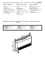
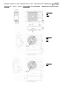
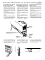
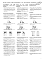
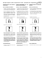
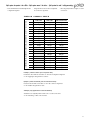
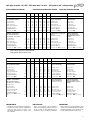
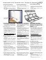
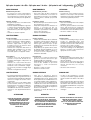
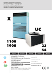
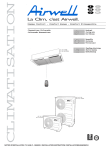
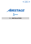
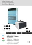
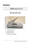
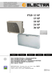
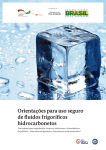
1 /* 2 GamaComfort-Gamaconfort-ComfortRange Split system da parete / da soffitto Split system mural / de techo Split system for Wall / ceiling mounting Sistema Split para parede / tecto Fredde soltanto Solo frio Cooling only Apenas refrigeração Pompa di calore Bomba de calor Heatpump PXD 9 RC 12 RC 15 RC 18 RC 24 RC 28 RC 32 RC Prima di installare l’apparecchio, leggere attentamente le presenti istruzioni. Conservatele per farvi riferimento ulteriormente. Lea atentamente estas instrucciones antes de iniciar la instalación y consérvelas para remitirse a ellas posteriormente. Read this instruction sheet carefully before installing, retain it safely for future reference. Antes de instalar o aparelho, leia esta folha de instruções cuidadosamente e por segurança guarde-a para futuras referências. ISTRUZIONI DI INSTALLAZIONE TH 3261 G - 399528 / INSTRUCCIONES DE INSTALLACION / INSTALLATION INSTRUCTION Split system da parete / da soffitto - Split system mural / de techo - Split system for wall / ceiling mounting MESSA FUORI TENSIONE PRIMA DI QUALSIASI INTERVENTO SULLE SCATOLE ELETTRICHE PUESTA FUERA DE TENSIÓN OBLIGATORIA ANTES DE CUALQUIER INTERVENCIÓN EN LAS CAJAS ELÉCTRICAS PXD IT IS MANDATYORY TO CUT OFF POWER SUPPLY BEFORE STARTING TO WORK IN THE ELECTRIC CASING BOXES. RACCOMANDAZIONI GENERALI RECOMENDACIONES GENERALES GENERAL RECOMMENDATIONS - Congratulazioni per avere scelto un condizionatore d’aria ELECTRA. - Ante todo, deseamos darle las gracias por haber elegido un equipo ELECTRA. - Congratulations for having selected an ELECTRA air conditioner. CONSIGLI DI SICUREZZA CONSEJOS DE SEGURIDAD SAFETY DIRECTIONS - In caso di intervento sul materiale, seguire le regole di sicurezza in vigore. - L’installazione e la manutenzione del materiale dovranno essere eseguite da personale qualificato. - Assicurarsi che l’alimentazione elettrica disponibile e la frequenza della rete siano adeguate alla corrente di funzionamento necessaria tenuto conto delle condizioni specifiche della zona di installazione e della corrente necessaria a tutti gli altri apparecchi collegati al circuito. - Cuando intervenga en su equipo, siga las reglas de seguridad en vigor. - La instalación y el mantenimiento deberán ser efectuados exclusivamente por personal cualificado. - Cerciórese de que la alimentación eléctrica disponible y la frecuencia de la red están adaptadas a la corriente de funcionamiento necesaria, teniendo en cuenta las condiciones específicas del emplazamiento y la corriente necesaria para cualquier otro aparato conectado al mismo circuito. - Follow the safety rules in force when you are working on your appliance. - Installation and maintenance of the equipment must only be performed by qualified specialists in accordance with the rules of good workmanship and prevailing standards and instructions. - Make sure that the power supply and its frequency are adapted to the required electric current of operation, taking into account specific conditions of the location and the current required for any other appliance connected with the same circuit. AVVERTENZA ADVERTENCIA - Prima di eseguire qualsiasi intervento o operazione di manutenzione, mettere fuori tensione l’apparecchio. - Il fabbricante declina qualsiasi responsabilità in caso di mancato rispetto delle presenti istruzioni. Inoltre, in questo caso la garanzia cesserà di essere valida. - In caso di difficoltà, si prega di contattare il Servizio Tecnico di zona. - Prima dell’installazione del materiale, procedere, se possibile al montaggio degli accessori obbligatori o meno (vedi manuale fornito con ogni accessorio). - Per una migliore conoscenza del prodotto, vi consigliano di consultare anche il nostro manuale tecnico. - Le informazioni contenute nelle presenti istruzioni sono soggette a modifiche senza preavviso. - Cortar la alimentación eléctrica general antes de cualquier intervención u operación de mantenimiento. - El fabricante declina toda responsabilidad y la garantía dejará de ser válida si no se respetan estas instrucciones de instalación. - En caso de problemas, recurra al Servicio Técnico de su zona. - Antes de la instalación, si fuera posible, monte los accesorios, obligatorios o no (ver las instrucciones entregadas con cada uno de ellos). - Para conocer mejor el producto, le recomendamos que consulte también nuestras instrucciones técnicas. - Las informaciones de este manual están sujetas a modificaciones sin previo aviso. WARNING - Cutoff power supply before starting to work on the appliance. - The manufacturer declines any responsibility and the warranty becomes void if these instructions are not respected. - If you meet a problem, please call the Technical Department of your area. - If possible, assemble the mandatory or optional accessories before placing the appliance on its final location.(see instructions provided with each accessory) - In order to become fully familiar with the appliance, we suggest to read also our Technical Instructions . - The information contained in these Instructions are subject to modification without advance notice. 2 Split system da parete / da soffitto - Split system mural / de techo - Split system for wall / ceiling mounting PXD INDICE SUMARIO SUMMARY DESCRIZIONE DESCRIPCIÓN DESCRIPTION Dimensioni dell’unità interna ...................... 4 Dimensioni dell’unità esterna ..................... 5 Dimensiones de la unidad interior .............. 4 Dimensiones de la unidad exterior ............. 5 Dimensions of Indoor Units ........................ 4 Dimensions of Outdoor Units ..................... 5 INSTALLAZIONE INSTALACIÓN INSTALLATION Localizzazione dell’unità esterna ............ 6-7 Localizzazione dell’unità interna ................ 8 Collegamento frigorifero ........................ 9-11 Installazione ......................................... 12-16 Specifiche frigorifere ............................ 17-18 Collegamenti elettrici ........................... 19-23 Emplazamiento de la unidad exterior ...... 6-7 Emplazamiento de la unidad interior .......... 8 Conexión frigorífica ................................ 9-11 Instalación ........................................... 12-16 Especificaciones frigorificas ................ 17-18 Conexiones eléctricas ......................... 19-23 Location of the Indoor Unit ...................... 6-7 Location of the Outdoor Unit ...................... 8 Refrigerant Line ..................................... 9-11 Installation ........................................... 12-16 Coolant specifications ......................... 17-18 Electrical Connections ......................... 19-23 FUNZIONAMENTO FUNCIONAMIENTO MAINTENANCE Manutenzione ...................................... 24-26 Mantenimiento ..................................... 24-26 Scheduled Maintenance ...................... 24-26 DICHIARAZIONE CE DI CONFORMITA’ DECLARACION CE DE CONFORMIDAD EC STATEMENT OF COMPLIANCE Fabbricante : Indirizzo : Fabricante: Dirección: Manufacturer: A.C.E. Address: 1bis, Av du 8 mai 1945 St-Quentin-en-Yvelines 78284 Guyancourt Cedex A.C.E. 1bis, Av du 8 mai 1945 St-Quentin-en-Yvelines 78284 Guyancourt Cedex A.C.E. 1bis, Av du 8 mai 1945 St-Quentin-en-Yvelines 78284 Guyancourt Cedex Dichiara qui di seguito che SPLIT DAVANZALE : Declara a continuación que SPLIT ALFEIZAR: Hereby states that: the air condensation sets in the SPLIT ALLEGE range, models: PXD 9RC - PXD 12RC - PXD 15RC - PXD 18RC - PXD 24RC - PXD 28RC - PXD 32RC PXD 9RC - PXD 12RC - PXD 15RC - PXD 18RC - PXD 24RC - PXD 28RC - PXD 32RC PXD 9RC - PXD 12RC - PXD 15RC - PXD 18RC - PXD 24RC - PXD 28RC - PXD 32RC e con il codice : 7 SP 01 y con el indicativo: 7 SP 01 and under the code: 7 SP 01 Sono conformi al disposto delle direttive CEE enunciate qui di seguito e alle disposizioni nazionali che le riconducono : Son conformes a las disposiciones de las directivas CEE enunciadas a continuación y a las legislaciones nacionales que las contemplan: Are in compliance with the provisions of the EEC directives mentioned hereunder and with the national legislation transposing them: Direttiva Macchina 98/37/CEE Direttiva Bassa Tensione (DBT) 73/23/CEE Direttiva Compatibilità Elettromagnetica 89/ 336/CEE Directiva Máquinas 98/37/CEE Directiva Baja tensión (DBT) 73/23/CEE Directiva compatibilidad Electromagnética 89/336/CEE Machines Directive 98/37/CEE Low tension Directive (DBT) 73/23/EEC Electromagnetic compatibility Directive 89/ 336/EEC and that e che : - sono stati applicati i seguenti paragrafi delle norme unificate : y que - se han aplicado los apartados siguientes de las normas armonizadas. the following paragraphs of the harmonized standards have been applied: NF EN 60 204-1 / 1998 NF EN 60 335-1 / 1995 NF EN 60 335-2-40 / 1994 NF EN 55 022 / 1998 NF EN 61 000-3-2 / 1998 NF EN 50 082-1 / 1998 NF EN 60 555-3 / 1992 NF EN 255 / 1997 NF EN 814 / 1997 Pr. EN 378 / 99 NF EN 60 204-1 / 1998 NF EN 60 335-1 / 1995 NF EN 60 335-2-40 / 1994 NF EN 55 022 / 1998 NF EN 61 000-3-2 / 1998 NF EN 50 082-1 / 1998 NF EN 60 555-3 / 1992 NF EN 255 / 1997 NF EN 814 / 1997 Pr. EN 378 / 99 NF EN 60 204-1 / 1998 NF EN 60 335-1 / 1995 NF EN 60 335-2-40 / 1994 NF EN 55 022 / 1998 NF EN 61 000-3-2 / 1998 NF EN 50 082-1 / 1998 NF EN 60 555-3 / 1992 NF EN 255 / 1997 NF EN 814 / 1997 Pr. EN 378 / 99 Fatto a : Tillières Sur Avre 27570 - FRANCIA In data :09/03/2000 Richard FALCO Direttore della Qualità Tillieres Sur Avre 27570 - FRANCIA El: 09/03/2000 Richard FALCO Director Calidad At Tillières sur Avre 27570 - FRANCE On: 09/03/2000 Richard FALCO Quality Director 3 Split system da parete / da soffitto - Split system mural / de techo - Split system for wall / ceiling mounting PXD COMPOSIZIONE DEL COLLO COMPOSICIÓN DEL PAQUETE CONTENTS OF PARCEL 1 PXD. 1 suppor to da parete (fornito montato sull’apparecchio) 1 sacchetto viteria 1 sacchetto documentazione 1 telecomando ad infrarossi + supporto 1 sagoma di posizionamento per i tubi di collegamento + collari di fissaggio dei tubi di collegamento 1 sagoma di montaggio (interasse di fissaggio) 1 cavo di collegamento sonda 1 filtro e relativo supporto. 1 PXD. 1 soporte mural (entregado montado en el aparato). 1 bolsa de tornillería. 1 bolsa de documentación. 1 mando a distancia IR + soporte. 1 plantilla de posicionamiento de los tubos de conexión + abrazaderas de fijación de los tubos de conexión. 1 plantilla de montaje (distancia entre ejes de fijación). 1 cable de conexión sonda. 1 filtro y su soporte. 1 PXD. 1 wall support. (supplied fitted to the unit). 1 bag containing hardware. 1 bag containing documentation. 1 IR remote control + support. 1 template for positioning connection tubing. + connection tubing fixing clamps 1 assembly template (distance between mounting holes) 1 sensor connecting cable 1 active charcoal filter and its support DIMENSIONI DELL’UNITÀ INTERNA DIMENSIONES DE LA UNIDAD INTERIOR DIMENSIONS OF INDOOR UNIT MODELLO 9 - 12 –15 –18 A = 820 mm MODELLI 24 – 28 –32 A = 1200 mm MODELOS 9 - 12 - 15 - 18 A = 820 mm MODELOS 24 -28 - 32 A = 1200 mm MODEL 9 - 12 - 15 - 18 A = 820mm MODEL 24 - 28 - 32 A = 1200mm $! A 4 Split system da parete / da soffitto - Split system mural / de techo - Split system for wall / ceiling mounting DIMENSIONI ESTERNE DELLE UNITÀ DIMENSIONES DE LAS UNIDADES EXTERIORES PXD DIMENSIONS OF OUTDOOR UNITS MODEL. 9 12 15 MODEL. 18 24 28 Ø 520 MODEL. 32 Ø 520 5 Split system da parete / da soffitto - Split system mural / de techo - Split system for wall / ceiling mounting INSTALLAZIONE INTERNA PXD PXD DELL’UNITÀ INSTALACIÓN DE LA UNIDAD INTERIOR PXD INSTALLATION OF THE PXD INDOOR UNIT - Installare il sostegno da parete del PXD per mezzo della sagoma di montaggio fornito con l’apparecchio. - Gli spazi liberi dell’apparecchio vengono indicati su questa sagoma. - Instalar el soporte mural del PXD utilizando la plantilla de montaje entregada con el aparato. - El espacio libre que debe respetarse alrededor de este aparato se indica en la plantilla. - Install the wall support of the PXD using the installation template supplied with the unit - The cut-outs for the unit are shown on this template. - Richiamo degli spazi liberi MINIMI da prevedere. - Recordatorio del espacio MÍNIMO que hay que prever. - Reminder of MINIMUM clearances to be provided. 900 mm 200 mm 80 mm 50 mm: Instalación en techo - ceiling mounted 20 mm: Instalación mural - wall mounted - Collegamenti frigoriferi possibili a destra, a sinistra e nella parte posteriore. - Possibilità di scarico delle condense: a destra, a sinistra, nella parte anteriore e posteriore (caso apparecchio da soffitto) (2 uscite per le condense sono disponibili sul recipiente di recupero: a destra e a sinistra). Uscita verso la parte posteriore Salida hacia la parte trasera Output to rear Uscita a sinistra Salida a la izquierda LH output - Las conexiones frigoríficas pueden realizarse a la derecha, a la izquierda y en la parte trasera. - Posibilidad de evacuación de los condensados: a la derecha, a la izquierda, en la parte frontal y en la parte trasera, si se trata de una instalación en techo (la bandeja de recuperación tiene 2 salidas de condensados: a la derecha y a la izquierda). - Coolant connections can be made on the LH side, on the RH side or at the rear. - Condensate evacuation possibilities: right, left, rear and front in the case of a ceiling mounted unit. (2 condensate outputs are available on the recovery tray). Collegamento sul PXD da isolare TASSATIVAMENTE Conexión en el PXD a aislar OBLIGATORIAMENTE Connection to the PXD to be MANDATORILY insulated Uscita a destra Salida a la derecha RH output Uscite a destra e a sinistra del recipiente di recupero delle condense Salidas a la derecha y a la izquierda de la bandeja de recuperación de condensados RH and LH outputs of condensate recovery tray Uscita delle condense (apparecchio da soffitto) Salida condensados en instalación en techo Condensate output in the case of a ceiling mounted unit 6 Split system da parete / da soffitto - Split system mural / de techo - Split system for wall / ceiling mounting PXD INSTALLAZIONE INSTALACIÓN INSTALLATION - Togliere el supporto da parete del PXD - Retirar el soporte mural fijado en la parte trasera de su PXD. - Remove the wall support mounted at the rear of your PXD - Per l’installazione del supporto da parete, posizionare la sagoma onde rispettare l’interasse dei fissaggio indicati su questo ultimo. - Para la instalación del soporte mural, colocar la plantilla para respetar la distancia entre ejes de las fijaciones indicadas en ella. - To install the wall support, locate the template in order to observe the correct distance between mounting holes marked on it. PRESTARE LA MASSIMA ATTENZIONE allo scarico delle condense: Dopo aver determinato l’uscita di questo scarico condense, (sinistra, destra, posteriore), assicurarsi durante l’installazione del supporto da parete di ottenere un’inclinazione favorevole per questo scarico. ATENCIÓN a la evacuación de los condensados: Después de haber determinado la salida de esta evacuación de condensados (izquierda, derecha, parte trasera), cuando se instale el sopor te mural, comprobar que la inclinación es favorable para esta evacuación. CAUTION - be careful with the condensate evacuation point: After determining the outlet for the condensate evacuation (LH, RH, rear), make sure that the wall mounting is installed with a slope which favours this evacuation. Scarico delle condense Evacuacion de los condensados Condensates evacuation - Fissare il supporto da parte con 4 viti (non fornite). - Fijar el soporte mural con 4 tornillos (no incluidos). - Attenzione a non mettere contropenza per lo scarico delle condense - Atención: No poner una contrapendiente para la evacuación de los condensados. - Take care to install unit with a positive slop for condensate drainage - Secure the wall support with 4 screws (not supplied) Fori di fissaggio per montaggio alla parete Orificios de fijación para enganche mural Mounting holes for wall installation Localizzazione delle aste filettate (Ø 8 mm max.) per montaggio al soffitto. Emplazamiento de las varillas roscadas (Ø 8 mm máx.) para un enganche en techo. Location of threaded rods (Dia 8 mm max.) for ceiling installation 7 Split system da parete / da soffitto - Split system mural / de techo - Split system for wall / ceiling mounting INSTALLAZIONE ESTERNA DELL’UNITÀ - Spazio libero minimo da prevedere (in mm) PXD INSTALACIÓN DE LA UNIDAD EXTERIOR INSTALLATION OF THE OUTDOOR UNIT - Espacio mínimo a prever (en mm). - Minimum clearance to respect (in mm). D 100 m m SOSPESO COLGADO SUSPENDED E Supporto da parete (non fornito) Soporte mural (no incluido) A AL SUOLO EN EL SUELO ON THE FLOOR Wall bracket (not supplied) D B B GC9-12-15 C Terminali di montaggio x 4 Almohadillas de montaje x 4 Mounting pads x 4 SCARICO DELLE CONDENSE EVACUACIÓN CONDENSADOS DE LOS 18-24-28-32 A 100 mm* 150 mm* B 100 mm* 150 mm* C 400 mm* 400 mm* D 500 mm* 500 mm* E 500 mm* 500 mm* *minimo * como mínimo DRAINING CONDENSATES 1) Orifizio Ø 17 mm 2) Connettore di scarico delle condense (accessorio) Ø 16 mm 1 Orificio Ø 17 mm 2 Conector de evacuación de los condensados (accesorios) Ø 16 mm 1 Hole Ø 17 mm Öffnung Ø 17 mm 2 Condensate drain connector (accesory) Ø 16 mm R Q ATTENZIONE Qualora l’unità esterna reversibile fosse installata in zone climatiche dove la temperatura esterna può essere inferiore à +1°C, è tassativo prevedere un sistema di prevenzione degli eventuali rischi di congelazione delle condense (esempio: cordone riscaldante). ATENCIÓN: Si la unidad exterior reversible se instala en zonas climáticas en las que la temperatura exterior pueda ser inferior a +1ºC, es necesario prever un sistema para evitar los eventuales riesgos de congelación de los condensados (cordón térmico, por ejemplo). CAUTION If the heat pump outdoor unit is installed in an area where the outdoor temperature may fall below +1°C, it is mandatory to provide a system preventing any risk of freezing of the condensate (e.g. heating wire). 8 Split system da parete / da soffitto - Split system mural / de techo - Split system for wall / ceiling mounting COLLEGAMENTI FRIGORIFERI PXD REFRIGERANT CONNECTIONS CONEXIONES FRIGORÍFICAS C E A D B D C L. MAX Höchstlänge L . MAX A B C D E Tubo “Gas” Tubo “Liquido” Dado Flare Isolamento dei tubi (6 mm minimo) Manicotto isolante A B C D E PX D L. (m) 9 12 12 15 1 5 -1 8 -2 4 -2 8 -3 2 25 Tubo “Gas” Tubo “Líquido” Tuerca Flare Aislamiento de los tubos (6mm míni.) Manguito aislante Model 9-12-15 A B C D E «Gaz» pipe «Liquid» pipe Flare nut Pipe insulation (6 mm min.) Insulation sleeve H = 7m MAX* * senza sifone * sin sifón * without siphon Model 18-24-28-32 H = 10m MAX - Posizionare un sifone sulla linea Gas ogni 3 metri. - Colocar cada 3 m. un sifón en la línea Gas. - Fit a siphon on the Gas line every 3m. - L’unità interna può essere installata al di sopra come al di sotto dell’unità. - I collegamenti FLARE sono disponibili come accessorio, in lunghezze fisse: 2,5 – 5 – 8 metri. - I tubi vengono forniti avvolti e dotati di dadi FLARE. - Srotolare accuratamente i tubi nel senso contrario delle spire per non piegare questi ultimi. - La unidad interior puede instalarse encima o debajo de la unidad. - Las conexiones FLARE están disponibles, como accesorio, en longitudes fijas: 2,5 - 5 - 8 m. - Los tubos se suministran enrollados y equipados de tuercas FLARE. - Desenrollar cuidadosamente los tubos en el sentido inverso a las espiras, para no plegarlos. - The indoor unit may be installed above or below the unit - The flare couplings are available as accessories in standard lengths of 2.5, 5 and 8 m. Cut to length on request from 9 to 12 . - The pipes are delivered coiled and equipped with flare nuts. - Carefully uncoil the pipes in the opposite direction from the turns so as not to flatten them. 9 Split system da parete / da soffitto - Split system mural / de techo - Split system for wall / ceiling mounting PXD POSIZIONAMENTO DEL TUBING SUL SUPPORTO DA PARETE INSTALACIÓN DEL TUBING SOBRE EL SOPORTE MURAL INSTALLATION OF TUBING ON WALL SUPPORT - Il principale vantaggio del vostro prodotto PXD è la possibilità di posizionare i tubi frigoriferi sul supporto da parete prima del posizionamento del vostro apparecchio (mediante utilizzo della sagoma fornita). NOTA: è tuttavia possibile fissare l’apparecchio alla parete prima del posizionamento dei tubi. - La principal ventaja de su producto PXD es la posibilidad de colocar los tubos frigoríficos sobre el soporte mural antes de instalar el aparato (utilizando la plantilla suministrada). NOTA: No obstante, es posible fijar el aparato al muro antes de instalar los tubos. - The main advantage of your PXD product is the possibility of locating the coolant tubing on the wall support before installing the unit (using the template supplied). - Posizionare la sagoma di posizionamento dei tubi sul supporto da parete. - Poner la plantilla de posicionamiento de los tubos en el soporte mural. - Place the tube locating template on the wall support. Apriete Press 2 Alloggiamento dei dadi FLARE Alojamiento de las tuercas FLARE Recess for FLARE nuts Infilare sotto l’orecchione Deslizar bajo la patilla Slide under bracket 3 Localizzazione dei collari serratubi Emplazamiento de las abrazaderas aprietatubos Location of tubing clamps I 4 devono mantenere il pezzo Los 4 deben sujetar la pieza All 4 must support the part 1 Mettere in appoggio Poner en apoyo Press fully home POSIZIONAMENTO DEL TUBING SUL SUPPORTO A PARETE INSTALACIÓN DEL TUBING SOBRE EL SOPORTE MURAL INSTALLATION OF TUBING ON WALL SUPPORT - Dopo aver scelto il vostro arrivo dei tubi frigoriferi (destra, sinistra o posteriore), si può realizzare il tubing. Occorrerà utilizzare la sagoma di montaggio onde incurvare correttamente i tubi per facilitare il collegamento. - Después de haber decidido la posición de llegada de los tubos frigoríficos (a la derecha, a la izquierda o en la parte trasera), se puede realizar el tubing. Para ello, utilice la plantilla de montaje con objeto de curvar los tubos correctamente y facilitar su conexión. - After choosing your coolant tubing input location (right, left or rear), you can set up your tubing. To do this, use the installation template in order to form the tubes correctly and thus facilitate connection. GAS LIQUIDO/ LIQUID Ø tubo GAS Ø tubo de GAS Ø GAS tube Ø tubo LIQUIDO Ø tubo de LIQUIDO Ø LIQUID tube PXD 9 3/8" 1/4" PXD 12 - 15 1/2" 1/4" 5/8" 3/8" PXD 18 - 24 PXD 28 - 32 10 Split system da parete / da soffitto - Split system mural / de techo - Split system for wall / ceiling mounting PXD POSIZIONAMENTO DEL TUBING SUL SUPPORTO DA PARETE INSTALACIÓN DEL TUBING SOBRE EL SOPORTE MURAL INSTALLATION OF TUBING ON WALL SUPPORT - Per una buona installazione dei tubi, posizionare il tubo LIQUIDO in alto ed il tubo GAS al di sotto di questo ultimo. - Para instalar correctamente los tubos, sitúe el tubo de LÍQUIDO encima y el tubo de GAS debajo. - Locate the LIQUID tube above the GAS tube. - Posizionare i dadi dei tubi (incurvati) nell’apposito alloggiamento della sagoma. - Mantenere i tubi i posizione mediante i collari in dotazione. - Togliere la sagoma tubi, si può quindi montare l’apparecchio sul suo supporto. - Ponga las tuercas de los tubos (curvados) en el alojamiento previsto en la plantilla. - Sujete los tubos con las abrazaderas suministradas. - Retire la plantilla de los tubos para poder montar el aparato en su soporte. - Fit the nuts of the (formed) tubing into the recess provided on the template. - Secure the tubing with the clamps provided. NOTA uscita verso la parte posteriore - Il foro inclinato permette di evitare l’ingresso delle condense o della pioggia. - Posizionare nel foro, un manicotto Ø 70 mm NOTA salida hacia la parte trasera - El orificio inclinado evita la entrada de los condensados o de la lluvia. - Coloque en el orificio un manguito Ø 70 mm. NOTE output to the rear - The slanted hole prevents condensates or rain from entering the unit. - Fit a Dia. 70 mm sleeve into the hole. A B 1 2 Lato esterno Lato interno Trapano Ø 70 mm Parete B A 5° 1 A B 1 2 - Remove the tubing template; you can now install your unit on its support. Lado exterior Lado interior Taladro Ø 70 mm Muro Outside Inside Drill Dia. 70 mm Wall 2 1 2 Tubo Liquido isolato Tubo de Líquido aislado Insulated liquid tube 3 A B 1 2 Tubo Gas isolato Tubo de Gas aislado Insulated gas tube Togliere la sagoma di tubo Retirar la plantilla de tubo Remove the template ATTENZIONE Proteggere i tubi onde non lasciare penetrare impurità nel circuito frigorifero. ATENCIÓN Proteger los tubos para que no penetren impurzas en el circuito frigorifico. WARNING The tubes must be closed to prevent impurities from entering Fissare i tubi con i collari di fissaggio in dotazione Sujetar los tubos con las abrazaderas de fijación suministradas Secure the tubing with the clamps provided 11 Split system da parete / da soffitto - Split system mural / de techo - Split system for wall / ceiling mounting INSTALLAZIONE INTERNA PXD DELL’UNITÀ - Sul PXD, smontare: La griglia di aspirazione Le fiancate destra e sinistra PXD INSTALACIÓN DE LA UNIDAD INTERIOR PXD INSTALLATION OF THE INDOOR UNIT PXD - En el PXD, desmontar: La rejilla de aspiración Los paneles laterales derecho e izquierdo - On the PXD, remove: The intake grid The LH and RH side panels 5 3 2 4* 2 5 1 Vite Tornillos Screws 4 *CORRETTO SCORRETTO *CORRECTO INCORRECTO *GOOD BAD FOR THE INTAKE GRID: PER LA GRIGLIA DI ASPIRAZIONE: PARA LA REJILLA DE ASPIRACIÓN: 1 Tirare la griglia in avanti. 2. Togliere le due viti di estremità. 3. Allentare la vite centrale senza toglierla interamente. 4. Sganciare la griglia. 1 Tirar de la rejilla hacia delante. 2 Retirar los dos tornillos de los extremos. 3 Aflojar el tornillo central sin retirarlo completamente. 4 Desenganchar la rejilla. PER LE FIANCATE: PARA LOS PANELES LATERALES: FOR THE SIDE PANELS: 5. Rimuovere le fiancata (movimento verso il basso). 5 Retirar los paneles laterales (movimiento hacia abajo). 5 Remove the side panels (downward movement) 1 Pull the grid forwards. 2 Remove the two end screws. 3 Unscrew the central screw, but do not remove it completely. 4 Unhook the grid. 12 Split system da parete / da soffitto - Split system mural / de techo - Split system for wall / ceiling mounting PXD INSTALLAZIONE DEL PXD SUL SUPPORTO DA PARETE INSTALACIÓN DEL PXD EN EL SOPORTE MURAL INSTALLATION OF THE PXD ON THE WALL SUPPORT - Vedi disegno di cui sotto per il montaggio del PXD. - Montaggio al soffitto (vedi NOTA di cui sotto). - Ver el croquis que figura a continuación para el montaje del PXD. - Montaje en techo (ver la NOTA a continuación). - Refer to the diagram below, for installation of the PXD. - Ceiling mounting (refer to the NOTE below). IMPERATIVE - In caso di montaggio dell’apparecchio al soffitto, mettere le due viti di bloccaggio (in dotazione) dell’apparecchio sul supporto. IMPERATIVE - En caso de una instalación en techo, poner los dos tornillos de bloqueo (suministrados) del aparato en el soporte. IMPERATIVE - For ceiling mounting, install the two clamp screws (provided) for the unit on the support. Instalación mural / wall mounted Instalación en techo / ceiling mounted 13 Split system da parete / da soffitto - Split system mural / de techo - Split system for wall / ceiling mounting PXD COLLEGAMENTO DEL TUBO DI SCARICO DELLE CONDENSE CONEXIONES DEL TUBO DE EVACUACIÓN DE CONDENSADOS CONNECTION OF CONDENSATE EVACUATION TUBE - L’acqua condensata deve essere direttamente scaricata verso l’esterno. Rispettare la pendenza della canalizzazione di scarico nel senso di scorrimento in caso di raccordo alla rete fognaria (2,5 cm/mm). - E’ necessario montare un sifone sulla canalizzazione di scarico e al di sotto del livello del recipiente di recupero dell’acqua dell’apparecchio. - Prevedere l’isolamento del tubo di scarico in caso di rischio di gelo o di condensa. - Scarico con kit pompa: (vedi manuale fornito con il kit). - L’apparecchio viene fornito con un tubo di scarico. - Le uscite sinistra e destra vengono otturate da un tappo. Non dimenticare di togliere il tappo prima di eseguire il collegamento del tubo di scarico. - El agua condensada debe ser evacuada directamente hacia el exterior. En caso de una conexión a la alcantarilla (2,5 cm/m), respetar la pendiente de la canalización de evacuación en el sentido de la circulación. - Es necesario instalar un sifón en la canalización de evacuación y por debajo del nivel de la bandeja de recuperación de agua del aparato. - En caso de riesgo de helada o de condensación, prever el aislamiento del tubo de evacuación. - Evacuación con kit bomba (ver las instrucciones suministradas con el kit). - El aparato se entrega con un tubo de evacuación. - Las salidas izquierda y derecha estan tapadas con un tapón. No olvidar retirarlo de conectar el tubo de evacuación. - Water condensation must be evacuated directly to the outside; observe an appropriate slope for the evacuation duct, which should slope downwards in the case of a connection to the wastewater system (2.5 cm/m slope). - An S-bend must be installed on the evacuation duct, below the level of the recovery tray of the unit. - Provide insulation for the evacuation tube in the case of a risk of freezing or condensation. - Evacuation with pump kit: (refer to instructions provided with kit). - The unit is supplied with an evacuation tube. - The right and left outlets are blocked off by a plug. Do not forget to remove this plug before connecting the evacuation tube. Fusible 3,15A Fusibile 3,15 A Fuse 3,15 A Tappo Tapón Plug Recipiente di recupero delle condense Bandeja de recuperación de condensados Condensate recovery tray Tubo LIQUIDO Tubo de LÍQUIDO LIQUID tube Tubo di scarico Tubo de evacuación Evacuation tube - In caso di un montaggio dell’apparecchio al soffitto, far scendere il tubo di scarico lungo la fiancata e fissarlo con collari come indicato nel disegno di cui sotto. Spaccare la parte preschiacciata situata nell’angolo della griglia di aspirazione. - En caso de una instalación con soporte de techo, hacer descender el tubo de evacuación a lo largo del panel lateral y fijarlo con abrazaderas como se indica a continuación. Romper también el prerrecortado en el ángulo de la rejilla de aspiración. Tubo GAS Tubo de GAS GAS tube - In the case of a ceiling mounted installation, run the evacuation tube down along the side panel and secure it with clamps as shown below. Also break the preformed cut-out in the corner of the intake grid. 14 Split system da parete / da soffitto - Split system mural / de techo - Split system for wall / ceiling mounting PXD DEI TUBI DELL’UNITÀ VACÍO DE LOS TUBOS FRIGORÍFICOS Y DE LA UNIDAD INTERIOR VACUUM OF COOLING PIPES AND INDOOR UNIT - Il carico in R22 viene immesso soltanto nel cassone esterno. L’unità interna contiene una piccola quantità di gas neutro. Pertanto dopo aver installato i collegamento, occorre tassativamente svuotare i collegamenti e l’unità interna. - La carga de R22 sólo se encuentra en la unidad exterior. La unidad interior contiene una pequeña cantidad de gas neutro. Por este motivo, después de haber instalado las conexiones hay que hacer el vacío obligatoriamente en las conexiones y en la unidad interior. - Only the outdoor unit is charged with R22 cooling fluid. The indoor unit contains a small quantity of a neutral gas. This the reason it is imperative to vacuum the linking pipes and the indoor unit. PROCEDURA DI MONTAGGIO PROCEDIMIENTO DE MONTAJE - Il gruppo esterno possiede una valvola che permette lo svuotamento dell’installazione (grossa valvola). 1. Collegare i tubi di collegamento al cassone esterno e all’unità interna. - Per ottenere un buon serraggio, ricoprire la superficie con dell’olio di refrigerazione. - El grupo exterior posee una válvula que permite hacer el vacío de la instalación (válvula grande). 1 Conectar los tubos de conexión a las unidades exterior e interior. - Para que el apriete sea correcto, cubrir la superficie con aceite de refrigeración. - The outdoor unit is equipped with a valve allowing to vacuum the installation (large valve) 1 Connect the connecting pipes to the outdoor unit by FLARE NUTS and to the indoor unit by BRAZING - To obtain the right tightening, cover the surface with cooling oil. - L’utilizzo di una controchiave è indispensabile per il serraggio delle valvole. - Es indispensable utilizar una contrallave para apretar las válvulas. - The use of a counter wrench is required to tighten the valves. - I valori della coppia di serraggio vengono riportati nella tabella di cui sotto - Los valores del par de apriete se indican en el siguiente cuadro. - The values of the tightening torque are shown in the table below. SVUOTAMENTO FRIGORIFERI E INTERNA ASSEMBLY Ø dei tubi Tubo 1 / 4” Tubo 3 / 8” Tubo 1 / 2 “ Tubo 5 / 8” Tubo 7 / 8 “ Coppia 15-20 Nm 30-35 Nm 50-54 Nm 70-75 Nm 90-95 Nm 1. Collegare la pompa a vuoto al raccordo flare del cassone esterno dotato della valvola di servizio (grosso raccordo). 2. Mettere la pompa a vuoto in funzione e verificare che l’ago dell’indicatore scenda a 0,2 mm Hg. La pompa deve funzionare per almeno 15 minuti. 3. Prima di togliere la pompa a vuoto, occorre verificare che l’indicatore di vuoto sia stabile per almeno cinque minuti. 4. Scollegare la pompa a vuoto e chiudere la valvola di servizio. 5. Togliere il tappo della valvola “GAS” e “LIQUIDO” e aprirli per mezzo di una chiave esagonale onde liberare l’R22 contenuto nel gruppo esterno. 6. Nel caso in cui il collegamento frigorifero di una via sia superiore a 4 metri, procedere al complemento di carico come dalle indicazioni contenute nella tabella B pagina 18. Alcune unità richiedono un’aggiunta di carico come dalle indicazioni contenute nella tabella A pagina 17. 7. Verificare la tenuta stagna dei collegamenti. Utilizzare un rilevatore di fuga elettronico o una spugna insaponata. Ø de los tubos Tubo 1 / 4” Tubo 3 / 8” Tubo 1 / 2 “ Tubo 5 / 8” Tubo 7 / 8 “ Par 15-20 Nm 30-35 Nm 50-54 Nm 70-75 Nm 90-95 Nm 1 Conectar la bomba de vacío al racor Flare de la unidad exterior equipada de la válvula de servicio (racor grande). 2 Poner la bomba de vacío en marcha y verificar que la aguja del indicador desciende a 0,2 mm Hg. La bomba debe funcionar durante 15 minutos como mínimo. 3 Antes de retirar la bomba de vacío, hay que verificar que el indicador de vacío se mantiene estable durante cinco minutos. 4 Desconectar la bomba de vacío y cerrar la válvula de servicio. 5 Retirar el tapón de las válvulas “GAS” y “LÍQUIDO”, y abrirlas con una llave hexagonal para liberar el R22 del grupo exterior. 6 En caso de que la conexión frigorífica de una vía sea superior a 4 m, efectuar un complemento de carga según indica el cuadro B de la página 18. Algunas unidades necesitan un complemento de carga según el cuadro A de la página 17. 7 Verificar la estanqueidad de las conexiones. Utilizar un detector de fugas electrónico o una esponja jabonosa. Ø of the Pipe Torque Pipe 1/4" Pipe 3/8" Pipe 1/2" Pipe 5/8" Pipe 7/8" 15-20 Nm 30-35 Nm 50-54 Nm 70-75 Nm 90-95 Nm 2 Connect the vacuum pump with the flare coupling of the outdoor unit equipped with a process valve. 3 Start the vacuum pump and check that the needle of the indicator goes down to - 0,2 mm Hg. The pump should run during at least 15 minutes. 4 Before disconnecting the vacuum pump, check that the vacuum indicator remains in the same position during five minutes. 5 Disconnect the vacuum pump. 6 Remove the cap of the "GAS" and "LIQUID" valves and open them with a hexagonal wrench to free the R22 contained in the outdoor unit. 7 If the length of the refrigerant pipes of one line exceeds 4m, add the extra charge indicated in the table B page 18. Certain units require an additional charge as per Table A page 17. 8 Check that the linking pipes are sealed. Use an electronic leak detector or a soapy sponge. 15 Split system da parete / da soffitto - Split system mural / de techo - Split system for wall / ceiling mounting PXD PARTICOLARITÀ DEI MODELLI REVERSIBILI PARTICULARIDADES DE LOS MODELOS REVERSIBLES SPECIFIC POINTS OF HEATPUMP MODELS PXD 18 E PXD 24 SOLTANTO PXD 18 Y PXD 24 ÚNICAMENTE PXD 18 and PXD 24 only - L’utilizzo del capillare supplementare (contrassegnato da un’etichetta rossa) è necessario soltanto al di sopra degli 8 metri. - La utilización del capilar suplementario (marcado con una etiqueta roja) sólo es realmente necesario a partir de 8 metros. - The use of the additional capillary (marked with a red label) is only needed at a length of more than 8 meters. - Al di sotto degli 8 metri, detto utilizzo è piuttosto pregiudizievole alla potenza calorifica (funzionamento invernale) e a una buona temperatura dell’olio del compressore; non è pertanto di lasciare questo ultimo in funzione. Ciò spiega perché occorre schiacciarlo come indicato sull’etichetta rossa. - Por debajo de 8 metros, es más bien perjudicial para la potencia calorífica (funcionamiento invierno) y para la correcta temperatura del aceite del compresor. Por tanto, no es conveniente dejarlo en servicio; hay que pinzarlo como se indica en la etiqueta roja. - If less than 8 meters it is rather detrimental to the heating capacity (winter operation) and to the right temperature of the compressor oil; therefore pinch the capillary as shown on the red label. - Capillare prima dello schiacciamento (la fibbia viene preparata in fabbrica) - Capilar antes del pinzamiento: (el bucle ha sido preparado en fábrica). - Capillary before pinching: (the loop is prepared at the factory) - Capillare dopo schiacciamento: - Capilar después del pinzamiento: - Capillary after pinching: - Questa operazione deve essere eseguita da un personale qualificato e secondo le regole dell’arte del frigorista. L’immissione del carico aggiuntivo viene eseguita a partire dalla valvola di servizio del raccordo del cassone esterno (raccordo grosso). - Esta operación debe ser efectuada por personal cualificado y siguiendo las normas de buena ejecución del frigorista. El complemento de carga se efectúa a través de la válvula de servicio del racor Flare de la unidad exterior (racor grande). - This operation should be done expertly by qualified personnel and (regrigeration engineer). The additional charge is to be added through the process valve of the flare coupling of the outdooor unit (large coupling). - Tutti gli interventi sui circuiti frigoriferi richiedono il rispetto delle norme internazionali ed europee in vigore (ISO S149-pr EN378-4-pr EN 13313) ed in Francia delle disposizioni contenute nel decreto del 30/06/98 riguardante l’utilizzo dei fluidi frigoriferi. - En todas las intervenciones en los circuitos frigoríficos se deben respetar las normas internacionales y europeas en vigor (ISO 5149-pr EN378-4-pr EN13313). En Francia, en particular, se exige el cumplimiento de las normativas del decreto de 30/06/1998 sobre la utilización de fluidos refrigerantes. - Any work carried out on the cooling circuits must comply with the international and European standards in force (ISO5149-prEN378-4-prEN13313), and in France with the regulations of the decree of 30/06/98 on the use of coolants. OPERAZIONI FINALI TAREAS FINALES FINAL OPERATIONS - Verificare che i tappi delle valvola siano correttamente serrati. - Comprobar que los tapones de las válvulas están bien apretados. - Check that the caps of the valves are tight. 16 Split system da parete / da soffitto - Split system mural / de techo - Split system for wall / ceiling mounting PXD SPECIFICHE FRIGORIFERE CARATTERISTICHE PXD 12 PXD 15 PXD 18 PXD 24 PXD 28 PXD 32 TUBO GAS Ø Tubo 1/2" 1/2" 5/8" 5/8" 5/8" 5/8" TUBO LIQUIDO Ø Tubo 1/4" 1/4" 3/8" 3/8" 3/8" 3/8" ~ 230V ~ 230V ~230V 3N ~ 400V ~230V/3N~400V ~230V/3N~400V ~230V/3N~400V GC réversibile 990 g 1240 g 1555 g 1540 g 2066 g 1970 g 2405 g Modello réversibile 150 g 0g 73 g 17 g 0g 0g 165 g PXD 12 PXD 15 PXD 18 PXD 24 PXD 28 PXD 32 Tensione alimentazione GC Carico nel gruppo esterno (carico immesso in fabbrica) per 4 metri TABELLA A Carico in R22 da aggiungere sul cantiere ESPECIFICACIONES FRIGORÍFICAS CARACTERISTICAS TUBO DE GAS Ø tubo 1/2" 1/2" 5/8" 5/8" 5/8" 5/8" TUBO DE LIQUIDO Ø tubo 1/4" 1/4" 3/8" 3/8" 3/8" 3/8" ~ 230V ~ 230V ~230V 3N ~ 400V ~230V/3N~400V ~230V/3N~400V ~230V/3N~400V GC reversible 990 g 1240 g 1555 g 1540 g 2066 g 1970 g 2405 g Modelo reversible 150 g 0g 73 g 17 g 0g 0g 165 g Tensión alimentación Carga en el grupo exterior (carga introducida en fábrica) para 4 m CUADRO A Carga de R22 añadir en obra COOLING SPECIFICATIONS SPECIFICATIONS PXD 12 PXD 15 PXD 18 PXD 24 PXD 28 PXD 32 GAS TUBE Tube Ø 1/2" 1/2" 5/8" 5/8" 5/8" 5/8" LIQUID TUBE Tube Ø 1/4" 1/4" 3/8" 3/8" 3/8" 3/8" ~ 230V ~ 230V ~230V 3N ~ 400V ~230V/3N~400V ~230V/3N~400V ~230V/3N~400V Heatpump GC 990 g 1240 g 1555 g 1540 g 2066 g 1970 g 2405 g Heatpump model 150 g 0g 73 g 17 g 0g 0g 165 g AC supply voltage Charge in outside unit (factory charged) for 4 m TABLE A R22 charge to be added on the site 17 Split system da parete / da soffitto - Split system mural / de techo - Split system for wall / ceiling mounting - Carico di R22in funzione della lunghezza dei collegamenti frigoriferi LUNGHEZZA DEI COLLEGAMENTI - LONGITUD DE LAS CONEXIONES / LENGTH OF CONNECTIONS TABELLA B - Carga de R22 en función de la longitud de las conexiones frigoríficas. PXD - R22 charge dependent of length of coolant connections CUADRO B TABLE B PXD 12 RC PXD 15 RC PXD 18-24-28-32 RC 5m 5 grs 15 grs 17 grs 6m 10 grs 30 grs 34 grs 7m 15 grs 45 grs 51 grs 8m 20 grs 60 grs 68 grs 9m 61 grs 75 grs 85 grs 10 m 70 grs 90 grs 102 grs 11 m 79 grs 105 grs 119 grs 12 m 88 grs 120 grs 136 grs 13 m 97 grs 135 grs 153 grs 14 m 106 grs 150 grs 170 grs 15 m 115 grs 165 grs 187 grs 16 m 180 grs 204 grs 17 m 195 grs 221 grs 18 m 210 grs 238 grs 19 m 225 grs 255 grs 20 m 240 grs 272 grs 21 m 255 grs 289 grs 22 m 270 grs 306 grs 23 m 285 grs 323 grs 24 m 300 grs 340 grs 25 m 315 grs 357 grs Esempio: (valevole soltanto per un impianto flare) Installazione di un PXD 15 reversibile con 15 metri di collegamenti frigoriferi: A + B = Aggiungere 165 g di R22 su cantiere. Ejemplo: (válido únicamente para una instalación Flare). Instalación de un PXD 15 reversible con 15 m de conexiones frigoríficas: A + B = Añadir: 165 g de R22 en obra. Example: (only applicable for a flare installation) Installation of a heatpump PXD 15 with 15 m of coolant connections: A + B = Add 165 g of R22 on the work-site. 18 Split system da parete / da soffitto - Split system mural / de techo - Split system for wall / ceiling mounting PXD COLLEGAMENTI ELETTRICI CONEXIONES ELÉCTRICAS ELECTRICAL CONNECTIONS Configurazione elettronica Configuración electrónica Electronic configuration ! DA ESEGUIRE FUORI TENSIONE EFECTUAR FUERA DE TENSIÓN - Il vostro apparecchio viene configurata in versione FREDDO SOLTANTO. - Per configurare in versione FREDDO SOLTANTO + Riscaldamento Termodinamico, procedere come segue: - Togliere la presa di configurazione contrassegnata ST e sostituirla con la presa di configurazione contrassegnata RC (fissata sulla scheda elettronica). - Scollegare la resistenza 4,7 KW e collegare il filo di sonda in dotazione. - Su aparato ha sido configurado en versión SÓLO FRÍO. - Para configurarlo en versión SÓLO FRÍO + Calefacción Termodinámica: - Retirar la toma de configuración marcada ST y cambiarla por la toma de configuración marcada RC (fijada en la tarjeta electrónica). - Desconectar la resistencia 4,7 kW y conectar el hilo de sonda suministrado. TO BE CARRIED OUT WITH THE ELECTRICAL SYSTEM DE-ENERGISED - Your unit is configured for COOLING ONLY. - To configure for HEATPUMP: - Remove the configuration connector marked ST and replace it with the configuration connector marked RC (mounted on the electronic circuit board) - Disconnect the 4,7 KÙ resistor and connect the sensor wire supplied (white). Plug di configurazione installato (RC) Plug de configuración instalado en fábrica (CR) Factory installed configuration plug (RC) Lato lamiera Lado chapa (metal panel side) Possibilità di far ruotare la scatola elettrica (togliere la vite) Es posible girar la caja eléctrica (retirar el tornillo) The control panel can be swung open (remove the screw) Cavi elettrici da installare come da specifiche allegate Cables eléctricos a instalar según las especificaciones adjuntas Electric cables to be installed according to attached specifications ATTENZIONE: Il plug possiede una piccola freccia che indica il senso di inserimento. La faccia dove si trova la freccia deve trovarsi verso la parte posteriore dell’apparecchio (sulla piastra elettrica, lato lamiera). ATENCIÓN: El plug posee una pequeña flecha para indicar el sentido de enchufado. La cara donde se encuentra la flecha debe estar hacia la parte trasera del aparato (en la pletina eléctrica, por el lado chapa). Verso il lato lamiera hacia el lado chapa 19 Split system da parete / da soffitto - Split system mural / de techo - Split system for wall / ceiling mounting PXD CONFIGURACIÓN DEL MANDO A DISTANCIA CONFIGURATION OF REMOTE CONTROL Per modificare la configurazione: Para cambiar de configuración: To change the configuration: 1 Togliere le pile. 2 Posizionare gli switch. 3 Eseguire TASSATIVAMENTE un RESET (vedi qui di seguito) 4 Rimettere le pile. 1 - Retirar las pilas. 2 - Posicionar los switchs. 3 - Efectuar OBLIGATORIAMENTE un RESET (ver a continuación). 4 - Colocar las pilas. CONFIGURAZIONE TELECOMANDO DEL Localizzazionedegliswitchperconfigurazione. Emplazamientodelosswitchsparaconfiguración. Location of configuration switches. 1 - Remove the batteries. 2 - Set the switches. 3 - MANDATORILY perform a RESET (see below). 4 - Reinstall the batteries. FUNZIONE RESET: 1) Togliere 1 pila. 2) Premere contemporaneamente i 4 tasti qui di seguito riportati fino a spegnimento dei simboli. 3) Rimettere la pila. R C -4 (R C L ) P /N 4 366 70 B atte ries : 2 x 1.5 V S ize : A A A, L R 03, A M G Localizzazione del pulsante RESET. Emplazamiento del botón RESET. Location of RESET button. RESET LIGHT I quattro tasti interessati sono: SET HOUR Standard Estándar CLR FUNCIÓN RESET: 1) Retirar 1 pila. 2) Mantener pulsadas simultáneamente estas 4 teclas hasta que se apaguen los símbolos. 3) Colocar la pila. Las cuatro teclas son las siguientes: Reversibile (senza modo Caldo / Freddo auto.) Reversible (sin modo Calor / Frío automático) Heat / Cool (without auto Cool / Heat mode) SET HOUR CLR RESET FUNCTION: Reversibile (tutti i modi disponibili) Reversible (todos los modos disponibles) Heat / Cool (all modes available) 1 - Remove one battery. 2 - Simultaneously press these 4 keys until the symbols are no longer displayed. 3 - Reinstall the battery. The four keys to be pressed are: SET HOUR CLR Modo Calor / Frío auto ático o modo sólo ventilación Auto Cool / Heat mode or fan mode 20 Split system da parete / da soffitto - Split system mural / de techo - Split system for wall / ceiling mounting SPECIFICHE ELETTRICHE ESPECIFICACIONES ELÉCTRICAS TIPO D'APPARECCHIO P X D 12 P X D 15 P X D 18 P X D 24 P X D 28 P X D 32 ~ 230 V - (1) * * * * * * FREDDO + VENTILAZIONE DEL RISCALDAMENTO THERMO PXD ELECTRIC SPECIFICATIONS TIPO DE APARATO TYPE OF APPLIANCE ~ 230 V - 50 H z ~ 230 V - 50 H z FRIO + VENTIL. o CALEFACCION TERMO. COOLING+VENTILATION OR THERMO HEATING Intensità nominale A 5,2 7,4 8,5 11,9 14,2 16,2 Intensidad nominal Nominal current Intensità maximale A 7,6 10,4 12 16 19,7 23,5 Intensidad maxima Maximum current Calibro fusibile aM A 8 12 12 16 20 25 Calibre fusible aM Fuse rating aM Calibro fusibile ASE/VDE* A 10 16 16 16 20 25 Calibre fusible ASE/VDE* Fuse rating ASE/VDE* 3 x 1,5 3 x 1,5 3 x 1,5 3 x 2,5 Sezione di cavo alim.* mm2 3 x 1,5 3 x 2,5 Sección de cable alim.* Collegamenti PXD / GC Sezione di cavo* ❄ ❊ Conexiones PXD / GC mm2 5 x 1,5 5 x 1,5 5 x 1,5 5 x 1,5 5 x 1,5 5 x 1,5 Sección de cable* ❄ ❊ MODO DEUMIDIFICAZIONE (FREDDO + VENTILAZIONE + RISCALD. ELETTRICO) OU Riscald.Thermo + Riscald. Elet. power supply cable* Linking pipes PXD / GC Cable section* ❄ ❊ MODO DESHUMIDIFICACION (FRIO + VENTILACION + CALEFACCION ELEC.) O Calor termo + Calor elec. DESHUMIDIFYING MODE (COOLING+VENTILATION +ELECTRIC HEATING) OR THERMO HEATING +ELECTRIC HEATING ntensità nominale A 9,5 11,7 12,8 18,4 20,7 22,7 Intensidad nominal Nominal current Intensità maximale A 12,8 15,6 17,2 23,9 27,6 31,4 Intensidad maxima Maximum current Calibro fusibile aM A 16 16 20 25 32 32 Calibre fusible aM Fuse rating aM Calibro fusibile ASE/VDE* A 16 16 20 25 35 35 Calibre fusible ASE/VDE* Fuse rating ASE/VDE* 3 x 1,5 3 x 2,5 3 x 2,5 3 x 2,5 Sezione di cavo alim.* mm2 3 x 1,5 3 x 2,5 Sección de cable alim.* Collegamenti PXD / GC Sezione di cavo* ❄ ❊ + riscald. elec (1) Conexiones PXD / GC mm2 5 x 1,5 5 x 1,5 5 x 1,5 5 x 1,5 5 x 2,5 5 x 2,5 Sección de cable* ❄ ❊ + calef. elec power supply cable** Linking pipes PXD / GC Cable section* ❄ ❊ + elec heating Specifiche valable per mod. 50 Hz et 60 Hz Datos válidos para mod. 50 Hz et 60 Hz Data valid for mod. 50 Hz et 60 Hz TIPO D'APPARECCHIO P X D 12 P X D 15 P X D 18 P X D 24 P X D 28 P X D 32 3 N ~ 400 V - 50 H z * * * * FREDDO + VENTILAZIONE DEL RISCALDAMENTO THERMO. TIPO DE APARATO TYPE OF APPLIANCE 3 N ~ 400 V - 50 H z 3 N ~ 400 V - 50 H z FRIO + VENTIL. o CALEFACCION TERMO. COOLING+VENTILATION OR THERMO HEATING Intensità nominale A 3,8 5,4 6 6,5 Intensidad nominal Nominal current Intensità maximale A 4,2 5,9 7,5 8,7 Intensidad maxima Maximum current Calibro fusibile aM A 6 6 10 10 Calibre fusible aM Fuse rating aM Calibro fusibile ASE/VDE* A 6 6 10 10 Calibre fusible ASE/VDE* Fuse rating ASE/VDE* 5 x 1,5 5 x 1,5 5 x 1,5 Sezione di cavo alim.* mm2 5 x 1,5 Sección de cable alim.* Collegamenti PXD / GC Sezione di cavo* ❄ ❊ Conexiones PXD / GC mm2 6 x 1,5 6 x 1,5 6 x 1,5 6 x 2,5 Sección de cable* ❄ ❊ MODO DEUMIDIFICAZIONE (FREDDO + VENTILAZIONE + RISCALD. ELETTRICO) OU Riscald.Thermo + Riscald. Elet. power supply cable* Linking pipes PXD / GC Cable section* ❄ ❊ MODO DESHUMIDIFICACION (FRIO + VENTILACION + CALEFACCION ELEC.) O Calor termo + Calor elec. DESHUMIDIFYING MODE (COOLING+VENTILATION +ELECTRIC HEATING) OR THERMO HEATING +ELECTRIC HEATING ntensità nominale Intensità maximale A 8,1 11,9 12,5 13 Intensidad nominal Nominal current Calibro fusibile aM A 9,4 13,8 15,4 16,6 Intensidad maxima Maximum current Calibro fusibile ASE/VDE* A 10 16 16 20 Calibre fusible aM Fuse rating aM Sezione di cavo alim.* A 10 16 16 20 Calibre fusible ASE/VDE* Fuse rating ASE/VDE* 5 x 1,5 5 x 1,5 5 x 1,5 Collegamenti PXD / GC Sezione di cavo* ❄ ❊ + riscald. el ec mm2 5 x 1,5 Sección de cable alim.* Conexiones PXD / GC mm2 6 x 1,5 6 x 1,5 6 x 1,5 6 x 2,5 Sección de cable* ❄ ❊+ calef. elec power supply cable** Linking pipes PXD / GC Cable section* ❄ ❊ + elec heating IMPORTANTE IMPORTANTE: IMPORTANT * Questi valori vengono dati a titolo indicativo, essi devono essere verificati e aggiustati in funzione delle norme in vigore: essi dipendono dall’installazione e della scelta dei conduttori. * Estos valores figuran a título indicativo. Deben ser verificados y ajustados en función de las normas en vigor; dependen de la instalación y de los conductores utilizados. * These values are given for guidance. They must be checked and adjusted according to prevailing standards. They depend on the system installed and the cables used. 21 Split system da parete / da soffitto - Split system mural / de techo - Split system for wall / ceiling mounting COLLEGAMENTI ELETTRICI CONEXIONES ELÉCTRICAS PXD ELECTRIC CONNECTIONS CON O SENZA RISCALDAMENTO ELETTRICO CON O SIN CALEFACCIÓN ELÉCTRICA WITH OR WITHOUT ELECTRIC HEATING CON O SENZA RISCALDAMENTO ELETTRICO CON O SIN CALEFACCIÓN ELÉCTRICA WITH OR WITHOUT ELECTRIC HEATING 22 Split system da parete / da soffitto - Split system mural / de techo - Split system for wall / ceiling mounting PXD CON E SENZA RISCALDAMENTO ELETTRICO CON E SIN CALEFACCIÓN ELÉCTRICA WITH AND WITHOUT ELECTRIC HEATING Protezione obbligatoria NON fornita Collegare il flo di sonda su OUT dopo aver tolto la resistenza Protección obligatoria NO incluida Conectar el hilo de sonda en OUT después de haber suprimido la resistencia. Mandatory protection device NOT supplied Connect the sensor wire to OUT after removing the resistor 23 Split system da parete / da soffitto - Split system mural / de techo - Split system for wall / ceiling mounting SPIE E DELL’APPARECCHIO COMANDI A B C D E INDICATOR LIGHTS CONTROLS ON THE UNIT INDICADORES LUMINOSOS Y MANDOS DEL APARATO F G H I J K PXD H M L H I L AND A J K L M A)RISCALDAMENTO Si accende durante il funzionamento. Riscalda e filtra l’aria del locale. Mantiene la temperatura ambiante desiderata. A)CALEFACCIÓN Se enciende durante el funcionamiento. Calienta y filtra el aire del local. Mantiene la temperatura ambiente deseada. A) HEATING Comes on during operation. Heating and filtration of the air in the room. Sustainment of required ambient temperature. B)FREDDO Si accende durante il funzionamento. Rinfresca, deumidifica e filtra l’aria ambiente. Mantiene la temperatura ambiente desiderata. B) FRÍO Se enciende durante el funcionamiento. Enfría, deshumidifica y filtra el aire ambiente. Mantiene la temperatura ambiente deseada. B) COOLING Comes on during operation. Cooling, dehumidification and filtration of the air in the room. Sustainment of required ambient temperature. C)VENTILAZIONE Si accende durante il funzionamento. L’apparecchio funziona soltanto in modo ventilazione. C)VENTILACIÓN Se enciende durante el funcionamiento. El aparato funciona únicamente en ventilación. C) VENTILATION Comes on during operation. The unit is running in ventilation mode only. D)SOTTO TENSIONE Si accende non appena l’apparecchio viene messo sotto tensione. D)EN TENSIÓN Se enciende desde la puesta en tensión. D) POWER Comes on as soon as the unit is energised. E)PROGRAMMAZIONE Si accende durante il funzionamento. Lampeggia per annunciare che il segnale del telecomando è stato ricevuto e memorizzato. E)PROGRAMACIÓN Se enciende durante el funcionamiento. Parpadea para anunciar que se ha recibido y memorizado la señal del mando a distancia. E) PROGRAMMING Comes on during operation. Flashes to indicate that the remote control signal has been received and stored in the memory. F) FILTRO Si accende quando il filtro ad aria deve essere pulito. Dopo la pulizia e il riposizionamento del filtro, il sistema deve essere reinizializzato (pulsante RESET). F) FILTRO Se enciende cuando es necesario limpiar el filtro de aire. Después de la limpieza y colocación del filtro, hay que reinicializar el sistema (botón RESET). F) FILTER Comes on when the air filter needs to be cleaned. After cleaning and re-installation of the filter, the system must be reset (RESET button). G) TEMPERATURA Visualizzata la temperatura impostata. 18 acceso = 18°C 20 acceso = 20°C 18 e 20 accesi = 19°C G) TEMPERATURA Visualiza la temperatura de consigna. 18 encendido = 18ºC 20 encendido = 20ºC 18 y 20 encendidos = 19ºC G) TEMPERATURE Displays the set temperature 18 lit = 18 °C 20 lit = 20 °C 18 & 20 lit = 19 °C H)VENTLATORE Velocità alta .H H)VENTILADOR Alta velocidad. H H) FAN High speed. H I) VENTILATORE Velocità media .M I) VENTILADOR Mediana velocidad. M I) FAN Medium speed. M J) VENTILATORE Velocità ridotta .L J) VENTILADOR Baja velocidad. L J) FAN Low speed. L K)VENTILATORE Ventilazione automatica .A K)VENTILADOR Ventilación automática. A K) FAN Automatic. A L) RESET Premere per spegnere il pulsante arancio dopo avere rimontato i filtri puliti. L) RESET Pulsar para apagar el indicador luminoso naranja, después de colocar los filtros limpios. L) RESET Press to switch off the indicator light and activate the filter function, after cleaning and re-installing the filter. Press to cancel the audible warning. M) ON / OFF Spia di accensione e di spegnimento dell’apparecchio. M) ON / OFF Indicador luminoso de funcionamiento y de parada del aparato M) ON/OFF Unit On/Off indicator light. 24 Split system da parete / da soffitto - Split system mural / de techo - Split system for wall / ceiling mounting PXD FILTRO ELETTROSTATICO FILTRO ELECTROSTÁTICO ACTIVE CHARCOAL FILTER - Un filtro elettrostatico, nonché il suo supporto vengono forniti con l’apparecchio (accessori). - Onde ottimizzare la filtrazione dell’aria, il filtro in questione può essere posizionato come segue. - Con el equipo se suministran como accesorios un filtro electrostático y un soporte. - Para optimizar la filtración del aire, puede instalarlo de la siguiente forma. - An active charcoal filter and its support are supplied as accessories with your product. (1 per filter) - In order to optimise air filtration, you can install it as follows. MANTENIMIENTO Y REPARACIÓN MAINTENANCE AND REPAIR BEFORE UNDERTAKING MAINTENANCE OPERATIONS, MAKE SURE THAT THE AIR CONDITIONER IS DISCONNECTED FROM THE MAINS. Pulizia del condizionatore - Strofinare l’unità interna con un panno morbido e asciutto o pulirlo con un aspirapolvere. - Non utilizzare acqua calda o prodotti detergenti volatili che potrebbero danneggiare il frontale del condizionatore. ANTES DE INICIAR LAS OPERACIONES DE MANTENIMIENTO, COMPROBAR QUE EL CLIMATIZADOR ESTÁ DESCONECTADO. Limpieza del filtro de aire El climatizador está equipado con un indicador luminoso de control del filtro de aire. Cuando este indicador luminoso F se enciende, puede limpiarse el filtro. - Para retirar el filtro, tirar hacia delante de la rejilla de aspiración y empujar los filtros ligeramente hacia abajo para desbloquearlos. - Reinicializar el aparato pulsando la tecla Reset. El indicador luminoso de control del filtro F se apaga. NO PONER EN FUNCIONAMIENTO EL CLIMATIZADOR SIN FILTRO! Limpieza del climatizador - Frotar la unidad interior con un trapo suave y seco, o limpiarla con un aspirador. - No utilizar agua caliente o detergentes volátiles que puedan deteriorar el frontal del climatizador. Precauzioni da prendere all’inizio della stagione - Verificare che non vi sia alcun ostacolo al flusso di aria aspirata ed immessa sulle due unità interna ed esterna- Verificare che il condizionatore sia correttamente collegato. Precauciones que hay que tomar al principio de la temporada - Verificar que no hay ningún obstáculo para el flujo de aire aspirado e impulsado, en las dos unidades interior y exterior. - Cerciorarse de que el climatizador está conectado correctamente. Precautions to be taken Protezione del sistema elettronico - L’unità interna e il telecomando non devono essere situati a meno di un metro di un televisore, di una radio o di qualsiasi altro elettrodomestico onde evitare le interferenze. - Proteggere l’unità interna contro i raggi del sole. Protección del sistema electrónico - La unidad interior y el mando a distancia no deben estar situados a menos de un metro de un televisor, una radio o cualquier otro electrodoméstico, para evitar interferencias. - Proteger la unidad interior de los rayos solares. Protection of the electronic system Sostituzione delle pile del telecomando - Togliere le pile del telecomando a partire della botola posteriore. - Utilizzare due pile da 1,5 di tipo AAA. - Le pile usate devono essere reciclate. Cambio de las pilas del mando a distancia - Retirar las pilas del mando a distancia por la trampilla trasera. - Utilizar dos pilas de 1,5 V de tipo AAA. - Las pilas gastadas deben recycled. Replacement of the remote control batteries Accesso al filtro Acceso al filtro Filter access MANUTENZIONE E RIPARAZIONE PRIMA DI ESEGUIRE LE OPERAZIONI DI MANUTENZIONE, VERIFICARE CHE IL CLIMATIZZATORE SIA FUORI TENSIONE. Pulizia del filtro ad aria - Il vostro condizionatore è dotato di una spia di controllo del filtro ad aria. Quando questa spia F si accende, il filtro deve essere pulito. - Per rimuovere il filtro, tirare in avanti la griglia di aspirazione, spingere leggermente i filtri verso il basso per aprirli. - Reinizializzare l’apparecchio premendo il tasto Reset. La spia di controllo del filtro F si spegne. NON FARE FUNZIONARE IL CONDIZIONATORE SENZA FILTRO! Cleaning of air filter Your air conditioner has an air filter clogging indicator light. When this indicator light F comes on, the filter must be cleaned. - To remove the filter, pull the inlet grid forward and press the filters slightly downwards to unclip them. - Reset the unit by pressing the Reset button. The filter indicator light F goes out. Do not operate the air conditioner without the filter ! Cleaning of the air conditioner - Rub the inside of the unit with a soft, dry cloth. - Do not use hot water or volatile detergents, which could damage the face of the air conditioner. - Check that there are no obstacles preventing the flow of inlet air and pulsed air, on both the indoor and outdoor units. - Check that the air conditioner is correctly connected. - The indoor unit and the remote control must not be located less than one metre from a television set, a radio or any other electrical appliance, in order to avoid interference. - Protect the unit against direct sunlight. - Remove the batteries from the remote control unit via the rear flap. - Fit two new 1.5 V type AAA dry cell batteries. - Used batteries must be recycled. 25 Split system da parete / da soffitto - Split system mural / de techo - Split system for wall / ceiling mounting PXD MANUTENZIONE MANTENIMIENTO SERVICING Manutenzione periodica - Per ottenere un corretto funzionamento dell’installazione, è necessario procedere a una manutenzione preventiva delle unità interna ed esterna da personale qualificato. Mantenimiento periódico - Para estar seguro de que la instalación funciona correctamente, es necesario un mantenimiento preventivo en las unidades interior y exterior, realizado por personal cualificado. Routine servicing - To ensure the correct operation of the installation, it is necessary to have preventive maintenance of the indoor and outdoor units carried out by qualified personnel. Impianto generale - Eseguire un’ispezione visiva dell’insieme dell’impianto in funzione. - Verificare la pulizia dell’impianto in generale e verificare che gli scarichi delle condense non siano otturati, in particolare quello dell’unità interna, prima della stagione estiva. - Verificare lo stato del recipiente. Instalación general - Efectuar una inspección visual del conjunto de la instalación en servicio. - Comprobar la limpieza de la instalación en general, y cerciorarse de que las evacuaciones de condensados no están obstruidas, especialmente la de la unidad interior, antes del verano. - Verificar el estado del depósito. General installation - Carry out a visual inspection of the complete installation in service. - Check the general cleanness of the installation, and check that the condensate evacuations are not blocked, particularly on the indoor unit, before the summer season. - Check the condition of the tray. UNITÀ ESTERNA UNIDAD EXTERIOR OUTDOOR UNIT Circuito frigorifero - Pulire lo scambiatore ad aria mediante un prodotto speciale per le batterie alluminiorame e risciacquare con acqua. Non utilizzare acqua calda né vapore. Ciò potrebbe provocare un aumento della pressione del refrigerante. - Verificare che la superficie delle alette in alluminio dello scambiatore non sia stata danneggiata da colpi o graffi, e se necessario, pulirla con l’apposito utensile. Circuito frigorífico - Limpiar el intercambiador de aire utilizando un producto especial para las baterías de aluminio-cobre, y enjuagar con agua. No utilizar agua caliente ni vapor, ya que podrían provocar un aumento de la presión del refrigerante. - Comprobar que la superficie de las aletas de aluminio del intercambiador no se ha deteriorado debido a golpes o arañazos y, si fuera necesario, limpiarlas con la herramienta adecuada. Coolant system - Clean the heat exchanger using a special product for aluminium-copper heat exchangers, and rinse with water. Do not use hot water or steam, as this could cause the pressure of the coolant to increase. - Check that the surface of the aluminium fins of the heat exchanger is not damaged by impacts or scratches, and clean with an appropriate tool if necessary. Parte elettrica - Verificare che il cavo di alimentazione generale non presenti alterazioni che potrebbero danneggiare il dispositivo di isolamento. - Verificare che i cavi di interconnessione situati tra le due unità non presentino alterazioni e siano correttamente collegati. - Se necessario, procedere al serraggio degli stessi. - Verificare il collegamento alla terra. Parte eléctrica - Verificar que el cable de alimentación general no presenta alteraciones que puedan perjudicar el aislamiento. - Comprobar que los cables de interconexión entre las dos unidades no presentan alteraciones y están correctamente conectados. - Apretarlos, si fuera necesario. - Verificar la conexión a tierra. Electrical section - Check that the main power supply cable is not damaged or altered in such a way as to affect the insulation - Check that the interconnecting cables between the two units are not damaged or altered, and that they are correctly connected. - Check the earth connection. UNITÀ INTERNA UNIDAD INTERIOR INDOOR UNIT - Per un buon funzionamento dell’impianto, è indispensabile pulire regolarmente il filtro a aria situato a livello dell’aspirazione dell’unità interna. Si consiglia di sostituire il filtro regolarmente. - Il filtro sporco provoca una riduzione della portata dell’aria attraverso la batteria dell’unità interna, il che riduce il rendimento dell’impianto e impedisce il buon raffreddamento del motore di ventilazione. - Verificare lo stato di pulizia della batteria interna. - Para que la instalación funcione correctamente, es indispensable limpiar con regularidad el filtro de aire, situado al nivel de la aspiración de la unidad interior. Se recomienda cambiar el filtro regularmente. - Un filtro sucio provoca una disminución del caudal de aire a través de la batería de la unidad interior, lo que reduce el rendimiento de la instalación y dificulta la refrigeración del motor de ventilación. - Comprobar el estado de limpieza de la batería interior. - In order for the installation to operate correctly, it is essential to regularly clean the air filter located in the intake of the indoor unit. - When clogged, the filter reduces the air flow through the heat exchanger of the indoor unit, which in turn reduces the efficiency of the installation and inhibits the cooling of the fan motor. - Check the cleanness of the indoor heat exchanger. ATTENZIONE ATENCIÓN: CAUTION PRIMA DI PROCEDERE A QUALSIASI MANIPOLAZIONE DEL MATERIALE, OCCORRE ASSICURARSI CHE L’ALIMENTAZIONE ELETTRICA SIA TOLTA ECHE NON ESISTI ALCUNA POSSIBILITÀ DI AVVIAMENTO IMPREVISTA. ANTES DE EFECTUAR CUALQUIER MANIPULACIÓN EN EL EQUIPO, ES CONVENIENTE ASEGURARSE DE QUE SE HA CORTADO LA ALIMENTACIÓN ELÉCTRICA Y DE QUE NO EXISTE NINGUNA POSIBILIDAD DE PUESTA EN MARCHA INESPERADA. BEFORE CARRYING OUT ANY OPERATION ON THE EQUIPMENT, CHECK THAT THE ELECTRICAL POWER SUPPLY IS SWITCHED OFF AND THAT IT CANNOT BE SWITCHED ON INADVERTENTLY. 26