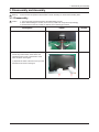
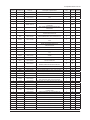
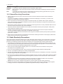
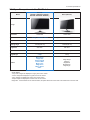
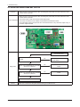
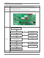
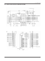
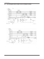
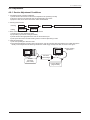
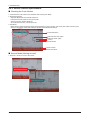
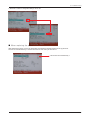
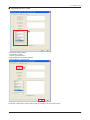
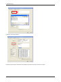
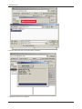
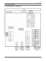
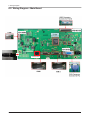
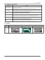
1
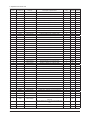
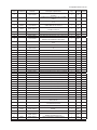
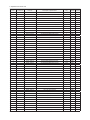
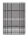
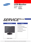
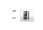
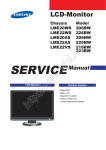
LCD-Monitor Chassis :LB522HS / LB522YS / LB523HS / LB524LS / LB524YS / LB524LS Model :BX2250 / BX2250N / BX2350 / BX2450 / BX2450N / BX2450L SERVICE TFT-LCD Monitor Manual Contens 1. Precautions 2. Product specifications 3. Disassembly and Reassemble 4. Troubleshooting 5. Exploded View & Part List 6. Wiring Diagram BX2250 / BX2250N / BX2350 / BX2450 / BX2450N / BX2450L Refer to the service manual in the GSPN (see the rear cover) for the more information. Contents 1. Precautions............................................................................................................... 1-1 1-1. Safety Precautions.......................................................................................................... 1-1 1-2. Servicing Precautions...................................................................................................... 1-2 1-3. Static Electricity Precautions........................................................................................... 1-2 1-4. Installation Precautions................................................................................................... 1-3 2. Product specifications............................................................................................. 2-1 2-1. Feature & Specifications.................................................................................................. 2-1 2-2. Spec Comparison to the Old Models............................................................................... 2-3 2-3. Accessories..................................................................................................................... 2-4 3. Disassembly and Assembly.................................................................................... 3-1 3-1. Disassembly.................................................................................................................... 3-1 4. Troubleshooting....................................................................................................... 4-1 4-1. Troubleshooting............................................................................................................... 4-1 4-2. When the power does Not Turn on.................................................................................. 4-2 4-3. When the screen is blank (Analog).................................................................................. 4-4 4-4. When a blank screen is displayed (Digital)...................................................................... 4-7 4-5. Error Examples and Actions.......................................................................................... 4-10 4-6. Adjustment..................................................................................................................... 4-11 5. Exploded View & Part List....................................................................................... 5-1 5-1. Exploded View.................................................................................................................. 5-1 5-2. Parts List........................................................................................................................... 5-2 6. Wiring Diagram......................................................................................................... 6-1 6-1. Wiring Diagram - Main Board.......................................................................................... 6-1 6-2. Wiring Diagram - IP Board............................................................................................... 6-2 6-3. Connector Functions....................................................................................................... 6-3 6-4. Cables............................................................................................................................. 6-3 GSPN (Global Service Partner Network) Area Web Site North America http://service.samsungportal.com Latin America http://latin.samsungportal.com CIS http://cis.samsungportal.com Europe http://europe.samsungportal.com China http://china.samsungportal.com Asia http://asia.samsungportal.com Mideast & Africa http://mea.samsungportal.com This Service Manual is a property of Samsung Electronics Co.,Ltd. Any unauthorized use of Manual can be punished under applicable International and/or domestic law. © 2010 Samsung Electronics Co.,Ltd. All rights reserved. Printed in Korea P/N: BN82-01098A-00 3. Disassembly and Assembly 3.DisassemblyandAssembly This section describes the disassembly and reassembly sequences for this monitor. Warning: As this monitor has parts that are sensitive to static electricity, be careful when handling them. 3-1.Disassembly Caution: 1. Turn the monitor off before beginning the disassembly process. 2. When disassembling the monitor, do not use any metal tools except for the provided jig. 3. Disassemble the monitor carefully as directed in the following procedures. Description Photo Screws 1. Remove the stand body shown in the figure. 2. ① Turn the monitor over and insert your hands into the top of the monitor at the center and separate the front cover in the direction of the arrow as shown in the figure. ② Separate the sides of the front cover up to the directed line as shown in the figure. 3-1 3. Disassembly and Assembly Description 3. Remove the LVDS, LAMP wire, FUNCTION cable, and then remove the SHIELD-COVER. 4. Remove the LCD panel. 5. Remove the four (2) screws shown in the figure. 6. Remove the fiive (3) screws shown in the figure and remove the Bracket support. 7. Remove the main PCB from the SHIELD-cover. ※The assembly is in the reverse order of disassembly. 3-2 Photo Screws 5. Exploded View & Part List 5. Exploded View & Part List 5-1. LS22B5HVFH/XF - Exploded View (BX2250) M0215 F001A R001A M0014 S001A CS02A 5-1-1. Parts List Location No. Code No. Description & Specification Q’ty SA/SNA CS02A BN96-14905C ASSY SHIELD P-COVER;50Series 23.6",SECC, 1 SNA F001A BN96-14906A ASSY COVER P-FRONT;50Series 21.5",ABS+PM 1 SA M0014 BN94-03654S ASSY PCB MAIN-ATZ;BX2250 1 SA M0215 BN07-00795A LCD-PANEL;M215HW01 V6,AU21507,6bit Hi-FR 1 SA R001A BN96-14923A ASSY COVER P-REAR;50Series 21.5",ABS,HB, 1 SA S001A BN96-14867A ASSY STAND P-SET;[LM] 50 SERIES,ABS,BK23 1 SA Remark 5-1 5. Exploded View & Part List 5-2. LS22B5HVFH/XF - Parts List (BX2250) Service Bom (SA: SERVICE AVAILABLE, SNA: SERVICE NOT AVAILABLE) Level Location No. 0.1 Code No. Description & Specification Q’ty SA/SNA Remark BN90-02842A ASSY COVER FRONT;BX2250,BLACK,High Gloss 1 SNA ..2 F001A BN96-14906A ASSY COVER P-FRONT;50Series 21.5",ABS+PM 1 SA ...3 W392 6003-000282 SCREW-TAPTYPE;BH,+,-,B,M3,L8,ZPC(BLK),SW 1 SA BN61-06695A GUIDE-PANEL;50Series,SECC T1.0,6.1mm 1 SNA CCM1 BN63-02183D COVER-SHEET;Rhcm,PE Vinyl,T0.04,680mm,20 0.5 SNA 1 SNA ...3 ...3 ...3 F001 BN63-07214A COVER-FRONT;50Series21.5",ABS+PMMA,HB ,TT ...3 T0527 BN68-00798D LABEL-ENERGY,STAR;L/M,W/W,PET,T0.05,9.3, 1 SNA ...3 FB20A BN96-15338B ASSY BOARD P-TOUCH FUNCTION;BX50,CT5000- 1 SA BN94-03856A ASSY PCB FUNCTION-BN9615338B;BX50,BN96- 1 SNA BN39-01298J LEAD CONNECTOR;BX50,LEAD CONNECTOR,UL 10 1 SNA .....5 BN97-04708A ASSY SMD-FUNCTION,BN9615338B;BX50,BN96- 1 SNA ......6 0406-001253 DIODE-TVS;VESD05A1-02V,6.0/6.8/7.5V,SOD- 1 SNA ....4 .....5 EC13 ......6 L0405 0601-002642 LED;SMD(SIDE VIEW),BLUE,475nm,3.8x1.0x0. 1 SNA ......6 HDR7 2007-000139 R-CHIP;220ohm,5%,1/16W,TP,1005 6 SNA ......6 VC37 2203-006048 C-CER,CHIP;100nF,10%,10V,X7R,TP,1005 1 SA ......6 AD480 2203-006399 C-CER,CHIP;1000nF,10%,6.3V,X5R,1005 1 SA ......6 T0052 2703-000296 INDUCTOR-SMD;680nH,10%,1608 1 SA ......6 HB01A 3711-005743 HEADER-BOARD TO CABLE;BOX,5P,1R,1.25mm,A 1 SA ......6 IS01A 1209-001838 IC-SENSOR;CT1C08,MLF,24P,4x4mm,PLASTIC,5 1 SA 1405-001233 VARISTOR;30Vdc,5A,1.6x0.8x0.8mm,TP 2 SA ......6 ......6 2007-000074 R-CHIP;100ohm,5%,1/10W,TP,1608 2 SA ......6 AR30 BN41-01522B PCB MAIN;BX50,Func,FR-4,2,MP1.0,1.6,119x 1 SNA ..2 BN68-03065B LABEL-MONITOR-POP;50 POP,WW,PET,T0.05,90 1 SNA ASSY COVER REAR;BX2250,BLACK,21.5 1 SNA 0.1 R001A BN90-02843B ..2 R001A BN96-14923A ASSY COVER P-REAR;50Series 21.5",ABS,HB, 1 SA 6003-001239 SCREW-TAPTYPE;FH,+,B,M4,L10,ZPC(WHT),S WR 2 SNA BN61-06702A HOLDER-STAND;[LM] 50 SERIES,POM,WHITE,AC 1 SNA ...3 M0081 ...3 ...3 ES02 BN61-06703A SPRING ETC;[LM] 50 SERIES,SK5,0.6,BLACKE 1 SNA ...3 SC05 BN63-07212A COVER-STAND;[LM] 50 SERIES,ABS,HB,BK23,E 1 SNA ...3 R001 BN63-07217A COVER-REAR;50Series21.5",ABS,HB 1 SNA BN91-04714A ASSY LCD-ATZ;BX2240 1 SNA 0.1 ..2 M0215 BN07-00795A LCD-PANEL;M215HW01 V6,AU21507,6bit Hi-FR 1 SA 0.1 M0017 BN91-05827C ASSY CHASSIS;BX2250 1 SNA ..2 M0081 6003-000264 SCREW-TAPTYPE;PWH,+,,B,M3,L6,ZPC(WHT),S 3 SA ..2 M0014 BN94-03654S ASSY PCB MAIN-ATZ;BX2250 1 SA ...3 0202-001463 SOLDER-WIRE;LFC2-W3.0,-,D3,99.79Sn/0.2Cu 1.814 SNA ...3 0202-001608 SOLDER-WIRE FLUX;LFC7-107,D0.8,99.3Sn/0. 0.233 SNA ...3 0204-002420 SOLVENT;1M-1000,C3H70H,96 3.47 SNA ...3 0204-002607 FLUX;DF-234U,13%,14KG,Gravity 0.82 2.259 SNA 5-2 5. Exploded View & Part List Level Location No. Code No. Description & Specification Q’ty ...3 AAE13 2401-000842 C-AL;220uF,20%,25V,WT,TP,8x11.5,5 1 SA ...3 C 2401-001218 C-AL;4.7uF,20%,100V,WT,TP,5x11,5 1 SA 3701-001510 CONNECTOR-DSUB;15P,3R,FEMAIL,STAMPED PIN 1 SNA ...3 ...3 JA330 SA/SNA Remark 3722-002758 JACK-PHONE;1P,BLK,STRAIGHT 1 SA ...3 3722-002922 JACK-DC POWER;3P,6.7mm,SnPb,Black 1 SNA ...3 BN97-00707A ASSY HDCP;BN46-00018A,BR20/21BS_ CS,MSTAR 1 SNA ....4 BN46-00018A KEY CODE-CERTIFICATE;(HDCP KEY) PPM42M5S, 1 SNA ...3 BN97-04471S ASSY SMD;BX2250,BN94-03654* 1 SNA ....4 0202-001477 SOLDER-CREAM;LST309M,D20~45um,96.5Sn/3A 0.462 SNA ....4 HD7 0401-000008 DIODESWITCHING;DAN217,80V,100MA,SOT-23, 4 SA ....4 DS01A 0401-001056 DIODE-SWITCHING;MMBD4148SE,100V,200m A,SO 3 SA ....4 DR01A 0402-001614 DIODE-RECTIFIER;S1G,400V,1A,DO-214AC,TP 2 SA 0403-001180 DIODE-ZENER;BZX84C6V2,5.86.6V,350mW,SOT 5 SA ....4 ....4 MZD1 ....4 0403-001411 DIODE-ZENER;5.49-5.73V,200mW,SOD-323,TP 6 SA 0403-001712 DIODE-ZENER;QZX363C6V8,6.47/7.14V,200mW, 1 SNA ....4 D0254 0404-001020 DIODE-SCHOTTKY;BAT54C,30V,200mA,SOT23,T 2 SA ....4 D0254 0404-001307 DIODE-SCHOTTKY;SSC54,20V,5000mA,DO214AB 1 SA ....4 T0139 0406-001271 DIODE-TVS;RCLAMP0524P,6/-/-V,150W,SLP251 4 SNA ....4 Q101 0501-000445 TR-SMALL SIGNAL;KTC3875SY,NPN,150mW,SOT 3 SA ....4 0501-002654 TR-SMALL SIGNAL;2PD601ASL,NPN,250mW,SOT- 6 SA ....4 0505-001089 FET-SILICON;AO3409L,P,-30V,-2.6A,0.097/0 1 SA ....4 0505-002421 FET-SILICON;AOD464,N,105V,40A,28mohm,100 1 SA FET-SILICON;AO6415,P,-20V,-3.3A,0.15ohm, 2 SA ....4 Q409 0505-002560 ....4 IC112 1103-000129 IC-EEPROM;24C02,2Kbit,256x8,SOP,8P,5x4mm 1 SA ....4 IC112 1103-001310 IC-EEPROM;24LC02B,256X8BIT,SOIC,8P,3.91X 2 SNA ....4 IC112 1103-001410 IC-EEPROM;S-24CS08AFJ-TB-1GE,8Kbit,1Kx8, 1 SNA 1 SA ....4 T0085 1201-002487 IC-AUDIO AMP;MAX9728A,QFN,12P,3x3mm,DUAL ....4 T0170 1203-003059 IC-SWITCH VOL. REG.;MP1583,SOIC,8P,4.9x3 1 SA ....4 T0087 1203-006118 IC-POSI.FIXED REG.;S-1172B18-U5T1G,SOT-8 1 SA ....4 T0087 1203-006141 IC-POSI.FIXED REG.;S-1172B33-U5T1G,SOT-8 1 SA 1203-006294 IC-BACKLIGHT DRIVER;MP3389EF,TSSOP,28P,9 2 SA 1205-003964 IC-LCD CONTROLLER;SE979LMRDLF,PQFP,128P 1 SA ....4 ....4 IC109 ....4 1405-001233 VARISTOR;30Vdc,5A,1.6x0.8x0.8mm,TP 2 SA DR1 2007-000043 R-CHIP;1Kohm,1%,1/10W,TP,1608 1 SA ....4 PR4 2007-000052 R-CHIP;10Kohm,1%,1/10W,TP,1608 2 SA ....4 KAR13 2007-000060 R-CHIP;100Kohm,1%,1/10W,TP,1608 3 SNA ....4 KAR21 2007-000070 R-CHIP;0ohm,5%,1/10W,TP,1608 9 SA ....4 CER02 2007-000071 R-CHIP;22ohm,5%,1/10W,TP,1608 2 SA ....4 AR30 2007-000074 R-CHIP;100ohm,5%,1/10W,TP,1608 8 SA ....4 FMR4 2007-000080 R-CHIP;2Kohm,5%,1/10W,TP,1608 2 SNA ....4 CER04 2007-000084 R-CHIP;4.7Kohm,5%,1/10W,TP,1608 3 SA ....4 5-3 5. Exploded View & Part List Level Location No. Code No. Description & Specification Q’ty ....4 MROP1 ....4 ARR2 SA/SNA Remark 2007-000090 R-CHIP;10Kohm,5%,1/10W,TP,1608 2 SA 2007-000102 R-CHIP;100Kohm,5%,1/10W,TP,1608 2 SA ....4 DR10 2007-000113 R-CHIP;33ohm,5%,1/10W,TP,1608 1 SA ....4 KAR11 2007-000124 R-CHIP;2.2Kohm,5%,1/10W,TP,1608 1 SNA ....4 MR604 2007-000137 R-CHIP;2Kohm,5%,1/16W,TP,1005 2 SNA ....4 R105 2007-000138 R-CHIP;100ohm,5%,1/16W,TP,1005 11 SA ....4 AR49 2007-000140 R-CHIP;1Kohm,5%,1/16W,TP,1005 2 SNA ....4 R319 2007-000143 R-CHIP;4.7Kohm,5%,1/16W,TP,1005 12 SNA ....4 PR27 2007-000144 R-CHIP;5.1Kohm,5%,1/16W,TP,1005 1 SNA ....4 R104 2007-000148 R-CHIP;10Kohm,5%,1/16W,TP,1005 19 SA ....4 MR13 2007-000157 R-CHIP;47Kohm,5%,1/16W,TP,1005 6 SNA ....4 DR39 2007-000162 R-CHIP;100Kohm,5%,1/16W,TP,1005 6 SNA ....4 HDR17 2007-000172 R-CHIP;10ohm,5%,1/16W,TP,1005 18 SNA ....4 2007-000563 R-CHIP;220Kohm,1%,1/10W,TP,1608 2 SA ....4 2007-000633 R-CHIP;270Kohm,1%,1/10W,TP,1608 2 SA ....4 2007-000736 R-CHIP;30Kohm,1%,1/10W,TP,1608 2 SA HR13 2007-000821 R-CHIP;390ohm,1%,1/10W,TP,1608 1 SNA ....4 V8932 2007-000857 R-CHIP;4.3Kohm,1%,1/10W,TP,1608 2 SNA ....4 R3508 2007-001038 R-CHIP;56Kohm,1%,1/10W,TP,1608 2 SA ....4 ....4 2007-001135 R-CHIP;68ohm,5%,1/4W,TP,3216 2 SA ZR10 2007-001164 R-CHIP;75ohm,1%,1/10W,TP,1608 3 SA ....4 OTR1 2007-001292 R-CHIP;33ohm,5%,1/16W,TP,1005 5 SNA ....4 AVR63 2007-001323 R-CHIP;3Kohm,5%,1/16W,TP,1005 2 SA ....4 ....4 2007-007132 R-CHIP;15Kohm,1%,1/16W,TP,1005 3 SA ....4 2007-007136 R-CHIP;4.7Kohm,1%,1/16W,TP,1005 1 SNA ....4 2007-007319 R-CHIP;390ohm,1%,1/16W,TP,1005 1 SNA ....4 2007-007463 R-CHIP;1.1Kohm,1%,1/16W,TP,1005 2 SA ....4 2007-009923 R-CHIP;0.3ohm,1%,1/4W,TP,3216 3 SNA ....4 C258 2203-000236 C-CER,CHIP;0.1nF,5%,50V,C0G,1608 5 SA ....4 C409 2203-000292 C-CER,CHIP;0.01nF,5%,50V,C0G,1608 2 SA ....4 C212 2203-000440 C-CER,CHIP;1nF,10%,50V,X7R,TP,1608 4 SA ....4 AD480 2203-000585 C-CER,CHIP;0.22nF,10%,50V,X7R,1005 2 SA ....4 ZC14 2203-000626 C-CER,CHIP;0.022nF,5%,50V,C0G,1608 1 SNA ....4 AD480 2203-002285 C-CER,CHIP;10nF,10%,50V,X7R,1005 1 SNA ....4 AD480 2203-002720 C-CER,CHIP;10nF,10%,25V,X7R,TP,1005 5 SNA ....4 DC108 2203-005005 C-CER,CHIP;100nF,10%,16V,X7R,1608 4 SC ....4 AAC1 2203-005249 C-CER,CHIP;100nF,10%,50V,X7R,TP,1608 1 SNA ....4 PC8 2203-005642 C-CER,CHIP;0.22nF,5%,50V,NP0,1005 2 SNA ....4 PC11 2203-006141 C-CER,CHIP;1000nF,10%,16V,X5R,1608 9 SNA ....4 C102 2203-006158 C-CER,CHIP;100nF,10%,16V,X7R,1005 36 SNA ....4 AD480 2203-006336 C-CER,CHIP;10000nF,10%,25V,X5R,3216 8 SA ....4 C234 2203-006378 C-CER,CHIP;4700nF,10%,6.3V,X5R,TP,1608 1 SNA ....4 AD480 2203-006698 C-CER,CHIP;1000nF,10%,25V,X7R,1608 2 SNA ....4 AD480 2203-007270 C-CER,CHIP;10000nF,10%,10V,X5R,TP,1608 26 SNA 1 SA ....4 X202 2801-003667 CRYSTAL-SMD;14.31818MHz,30ppm,28AAN,16p ....4 L2011 3301-001145 BEAD-SMD;60ohm,4516,TP,70ohm/45MHz,82o hm 6 SNA ....4 T0568 3301-001176 BEAD-SMD;80ohm,2012,TP,-,- 3 SNA ....4 T0568 3301-001407 BEAD-SMD;30ohm,1608,300mA,TP,,,0.4ohm 2 SNA 5-4 5. Exploded View & Part List Level Location No. ....4 Code No. Description & Specification Q’ty SA/SNA Remark 3601-001038 FUSE-SURFACE MOUNT;125V,3A,FASTACTING,C 1 SA ....4 AC510 3708-001150 CONNECTOR-FPC/FFC/PIC;30P,1mm,SMDA,SN,Y 1 SA ....4 AC510 3708-001779 CONNECTOR-FPC/FFC/PIC;20P,0.5mm,SMDA,Au 1 SNA ....4 HB01A 3711-005743 HEADER-BOARD TO CABLE;BOX,5P,1R,1.25mm,A 1 SA ....4 T0010 BN27-00007A COIL CHOKE-SMD;DHB0504100,RB15/17NS,10u 1 SA ....4 T0010 BN27-00009A COIL CHOKE;SMD 12x12x6,EOS,33uH,15%,0.12 1 SA ....4 BN41-01483A PCB MAIN;50series 1analog+2hdmi,FR-4,2,M 1 SNA ....4 BN97-04543C ASSY MICOM;m-B522H0CLA-1002.1,2010.05.25 1 SNA .....5 1107-001938 IC-FLASH MEMORY;W25X40BVSSIG,4Mbit,SOP,8 1 SNA ....4 3701-001591 CONNECTOR-HDMI;19P,2ROW,FEMALE,SMDS,AU 2 SNA ....4 2703-003866 INDUCTOR-SMD;22uH,20%,10.5x10.5mm 1 SA ....4 0404-001595 DIODE-SCHOTTKY;B2100,100V,2000mA,SMB, TP 1 SA ....4 AAR11 2007-000312 R-CHIP;10ohm,5%,1/4W,TP,3216 1 SA ....4 ER19 2007-002899 R-CHIP;10ohm,1%,1/10W,TP,1608 1 SA ....4 AD480 2203-007602 C-CER,CHIP;2200nF,10%,100V,X7R,TP,3225 1 SA ....4 WR15B 2007-001044 R-CHIP;56ohm,5%,1/10W,TP,1608 2 SA ....4 C3 2203-000384 C-CER,CHIP;0.015nF,5%,50V,C0G,1608 1 SNA ....4 AAC14 2203-000888 C-CER,CHIP;4.7nF,10%,50V,X7R,TP,1608 6 SA 1405-001185 VARISTOR;24Vdc,1.6x0.8x0.36mm,TP 2 SA 0201-001059 ADHESIVE-SIL;#9590,WHT,CARTRIGE 0.001 SNA BN96-14905C ASSY SHIELD P-COVER;50Series 23.6",SECC, 1 SNA BN61-06624A BRACKET-FRAME;50Series 24",SECC,T0.8 1 SNA BN63-07206C SHIELD-MAIN;50Series23.6",SECC,T0.8,HDMI 1 SNA ....4 ...3 ..2 CS02A ...3 CB02 ...3 ...3 T0073 AA63-01110C GASKET-EMI;42D5,1.0,10,22,45Kg/m2,Fabric 1 SNA ...3 M0131 AA63-01134A GASKET;JD26KO,Conductive Fabric,10mm,1.5 1 SNA ...3 BN60-00231A SPACER-FELT;FELT,15,BLK,T0.3,15 2 SNA ..2 FL06 BN96-12453J ASSY CABLE P-FFC;50Series,LVDS CABLE,P10 1 SA ..2 CIS1 BN74-00021A TAPE-FILAMENT;Filament tape,clear,#8915, 0.06 SNA BN91-05829A ASSY SHIELD;BX2250N 1 SNA SNA 0.1 ..2 CIS1 BN74-00021A TAPE-FILAMENT;Filament tape,clear,#8915, 0.3 ..2 FL06 BN96-13895D ASSY CABLE P-FFC;Cobalt,FFC CABLE,JPC-S0 1 SA BN92-05486K ASSY LABEL;BX50 1 SNA 0.1 ..2 CCM1 BN68-01570A LABEL RATING;ALL,SS,PE,T0.05,90,45,Dark 1 SNA BN92-06358G ASSY BOX;BX2250,LS22B5HVFH/XF 1 SNA BH68-00329D LABEL BAR CODE-02;NO CE,NO WT`Y,MPRII,LA 1 SNA ..2 BH68-00651R LABEL BOX-00;ALL MODEL,MOJO 90G,90,95,WH 1 SNA ..2 BN68-02882T LABEL-STICKER;MODEL 15,CHINA,MOJO,80G,54 1 SNA ..2 BN69-05258A BOX-01,SET;Series 50 21.5",PAPER,SW,A1,Y 2 SNA BN96-02895A ASSY MISC P-01,HANDLE PACKING;ALL MODEL, 1 SNA ...3 BN66-00007A LEVER-TOP;ALL MODEL,LDPE,WHITE,5.8g 1 SNA ...3 BN66-00008A LEVER-BOTTOM;ALL MODEL,LDPE,WHITE,4.01g 1 SNA BN92-06359F ASSY ACCESSORY;LS22B5HVFH/XF 1 SNA 0.1 ..2 ..2 0.1 T0077 M0245 ACCE1 5-5 5. Exploded View & Part List Level Location No. Code No. Description & Specification Q’ty ..2 EC29 BN39-00244H CBF SIGNAL-D-SUB TO D-SUB;D-sub cable,15 1 SA ..2 M0158 BN44-00139C DC VSS(A);AD-3612S,WHITE,110/230V,50/60H 1 SA ...3 BN81-00713A A/S-DIODE-RECTIFIER;0402-000602,-,-,-,-, 1 SNA ...3 BN81-00944A A/S-FUSE-AXIAL LEAD;3601-001301,-,-,-,-, 1 SNA ...3 BN81-00951A A/S-WIRE-NO SHEATH CU;3811-000545,-,-,-, 1 SNA ...3 BN81-00955A A/S-EYELET;6042-001007,-,-,-,-,-,- 1 SNA ...3 BN81-00970A A/S-COIL-LFT;ML27-00096A,-,-,-,-,-,- 1 SNA ...3 BN81-01058A A/S-SOLDER-WIRE FLUX;0202-001253 1 SNA ...3 BN81-01060A A/S-GREASA-SILIWNE;ML74-00120A 0.1 SNA ...3 BN81-01061A A/S-FLUX;0204-002413 0.2 SNA ...3 BN81-01062A A/S-ADHESIVE-ANB;0201-000215 0.01 SNA ...3 BN81-01102A A/S-SOLDER-WIRE;0202-001547 1 SNA ...3 BN81-01104A A/S-SOLDER-WIRE;0202-001594 1 SNA ...3 BN81-01158A A/S-R-CHIP;2007-008126 3 SNA ...3 BN81-01159A A/S-R-CHIP;2007-008828 1 SNA ...3 BN81-01160A A/S-R-CHIP;2007-008832 1 SNA ...3 BN81-01161A A/S-R-CHIP;2007-008836 1 SNA ...3 BN81-01163A A/S-R-CHIP;2007-008840 2 SNA ...3 BN81-01177A A/S-R-CHIP;2007-009656 1 SNA ...3 BN81-01430A A/S-LABEL;ML68-02001Q,-,-,-,-,-,- 1 SNA ...3 BN81-01526A A/S-CAPACITOR-MLCC;ML59-00006G,-,-,-,-,- 1 SNA ...3 BN81-01626A A/S-R-CHIP;2007-009671,-,-,-,-,-,- 1 SNA ...3 BN81-02563A A/S-R-CHIP;2007-008925 1 SNA ...3 BN81-02613A A/S-BEAD-AXIAL;3301-001982 1 SNA ...3 BN81-02900A A/S-ADHESIVE-SL;0201-002112 0.006 SNA ...3 BN81-02901A A/S-SOLDER BAR;0202-001695 2.4 SNA ...3 BN81-02902A A/S-SOLDER WIRE;0202-001703 0.001 SNA ...3 BN81-02921A A/S-MLCC-CHIP;ML59-00005T 2 SNA ...3 BN81-03067A A/S-BAR CODE LABEL;ML68-00582L 1 SNA ...3 BN81-03176A A/S-SOLDER-BAR;0202-001692 2.4 SNA ...3 BN81-03177A A/S-SOLDER-BAR;0202-001693 2.4 SNA ...3 BN81-03178A A/S-SOLDER-WIRE;0202-001696 0.001 SNA ...3 BN81-03179A A/S-SOLDER-BAR;0202-001697 2.4 SNA ...3 BN81-03333A A/S-TUBE-TEFRON TUBE;ML62-00231A 0.02 SNA ...3 BN81-04632A A/S-DIODE ZENER;0403-001775 1 SNA ...3 BN81-05360A A/S-ADHESIVE-SIL;0201-001941 6 SNA ...3 BN81-05361A A/S-ADHESIVE-SL;0201-002214 6 SNA ...3 BN81-05434A A/S-BOX-OUT;ML69-00397Y 1 SNA ...3 BN81-05435A A/S-C-AL;2401-004694 2 SNA ...3 BN81-05436A A/S-C-AL;2401-004695 1 SNA ...3 BN81-05437A A/S-C-AL;2401-004700 2 SNA ...3 BN81-05441A A/S-C-CER,CHIP;2203-005135 1 SNA ...3 BN81-05442A A/S-C-CER,CHIP;2203-006428 1 SNA ...3 BN81-05443A A/S-C-CER,CHIP;2203-006596 1 SNA ...3 BN81-05444A A/S-C-CER,CHIP;2203-007466 1 SNA ...3 BN81-05446A A/S-C-CERAMIC,DISC;2201-002379 1 SNA ...3 BN81-05448A A/S-C-FILM,LEAD;2301-001975 1 SNA ...3 BN81-05450A A/S-CHIP-R;ML01-00025H 1 SNA ...3 BN81-05451A A/S-COIL CHOKE;ML27-00418N 1 SNA ...3 BN81-05454A A/S-COIL FILTER-LINE;ML27-00429D 1 SNA ...3 BN81-05455A A/S-DIODE-BRIDGE;0402-001821 1 SNA 5-6 SA/SNA Remark 5. Exploded View & Part List Level Location No. Code No. Description & Specification Q’ty SA/SNA Remark ...3 BN81-05456A A/S-DIODE-RECTIFIER;0402-001741 1 SNA ...3 BN81-05458A A/S-DIODE-SCHOTTKY;0404-001539 1 SNA ...3 BN81-05460A A/S-DIODE-TVS;0406-001396 1 SNA ...3 BN81-05463A A/S-DIODE-ZENER;0403-001796 1 SNA ...3 BN81-05465A A/S-IC-POSI.ADJUST REG.;1203-005361 1 SNA ...3 BN81-05467A A/S-IC-PWM CONTROLLER;1203-006085 1 SNA ...3 BN81-05468A A/S-PACKING-VINYL BAG;ML69-00382F 1 SNA ...3 BN81-05469A A/S-PAD-CROSS (A);ML69-00400T 1 SNA ...3 BN81-05470A A/S-PAD-CROSS (B);ML69-00400S 1 SNA ...3 BN81-05471A A/S-PAD-NIL;ML69-00398Y 1 SNA ...3 BN81-05473A A/S-PCB;ML41-00415Y 1 SNA ...3 BN81-05475A A/S-PHOTO-COUPLER;0604-001294 1 SNA ...3 BN81-05481A A/S-R-CHIP;2007-008871 1 SNA ...3 BN81-05482A A/S-R-CHIP;2007-009733 3 SNA ...3 BN81-05483A A/S-R-CHIP;2007-009840 1 SNA ...3 BN81-05485A A/S-THERMISTOR-NTC;1404-001552 1 SNA ...3 BN81-05488A A/S-TRANS-POWER S/W;ML26-00403U 1 SNA ...3 BN81-05490A A/S-VARISTOR;1405-001278 1 SNA ...3 BN81-05491A A/S-CHIP-R;ML01-00024A 2 SNA ...3 BN81-05492A A/S-CAPACITOR-MLCC;ML59-00009Q 4 SNA ...3 BN81-05552A A/S-SCREW-MACHINE;6001-001863 1 SNA ...3 BN81-05553A A/S-NUT-HEXAGON;6021-000139 1 SNA ...3 BN81-05554A A/S-DC POWER CABLE;ML39-00603M 1 SNA ...3 BN81-05555A A/S-DC POWER CABLE;ML39-00603L 1 SNA ...3 BN81-05556A A/S-HARNESS SOCKET-ASSY INLET;ML39-00607 1 SNA ...3 BN81-05557A A/S-HARNESS SOCKET-ASSY INLET;ML39-00607 1 SNA ...3 BN81-05558A A/S-CASE-BOTTOM;ML61-00158A 1 SNA ...3 BN81-05559A A/S-CASE-COVER;ML61-00158B 1 SNA ...3 BN81-05560A A/S-SUPPORT-SPACER;ML61-00159B 3 SNA ...3 BN81-05561A A/S-PAD GAP-#1;ML62-00270N 1 SNA ...3 BN81-05562A A/S-PAD GAP-#2;ML62-00270P 1 SNA ...3 BN81-05563A A/S-PAD GAP-#3;ML62-00270Q 1 SNA ...3 BN81-05564A A/S-HEAT SINK-#2;ML62-00293H 1 SNA ...3 BN81-05565A A/S-HEAT SINK-#1;ML62-00293K 1 SNA ...3 BN81-05566A A/S-SHIELD-COVER;ML63-00022F 1 SNA ...3 BN81-05567A A/S-SHIELD-BOTTOM;ML63-00022G 1 SNA ...3 BN81-05568A A/S-LABEL RATING;ML68-00592D 1 SNA ...3 BN81-05569A A/S-TAPE ETC;ML02-00006H 0.12 SNA ...3 BN81-05570A A/S-TAPE ETC;ML02-00006J 1 SNA BN96-14867A ASSY STAND P-SET;[LM] 50 SERIES,ABS,BK23 1 SA 2 SNA ..2 M0014 S001A ...3 M0081 6003-001001 SCREW-TAPTYPE;FH,+,B,M3,L8,ZPC(BLK),SW RC ...3 M0081 6003-001019 SCREW-TAPTYPE;RH,+,B,M4,L12,ZPC(BLK),S WR 2 SNA ...3 BN61-06627A BRACKET-STAND BODY;[LM] 50 SERIES,SECC,T 1 SNA ...3 BN61-06676A BRACKET-STAND BASE;[LM] 50 SERIES [18.5] 1 SNA ...3 BN63-07262A COVER-STAND FRONT;[LM] 50 SERIES [18.5-2 1 SNA BN73-00077A RUBBER FOOT;MATISSE,BUMPON,#13.5,T2.0 ,60 4 SNA ...3 AR011 5-7 5. Exploded View & Part List Level Location No. Code No. Description & Specification Q’ty SA/SNA Remark ...3 M0081 6003-000131 SCREW-TAPTYPE;BH,+,S,M4,L6,ZPC(BLK),SW RC 4 SNA ...3 T0524 6902-000389 BAG PE;HDPE/NITRON/HDPE,T0.015/T0.5/T0.0 1 SNA ...3 AA63-60131Z SPACER-FELT;35/50 LCD-MONITOR,felt,16,bl 4 SNA ...3 BN63-07263B COVER-STAND REAR;[LM] 35/50 SERIES [18.5 1 SNA ...3 BN68-03045B LABEL-STICKER;[50 series][18.5-21.5],W/W 1 SNA ...3 BN68-03048A LABEL-WARNING;50SERIES,ALL,PE,T0.05,16,4 1 SNA 6003-001010 SCREW-TAPTYPE;FH,+,B,M3,L6,ZPC(WHT),S WRC 4 SNA ...3 M0081 ...3 AA60-00189A SPACER-FELT;35/50 LCD-MONITOR,felt,L30,b 1 SNA ..2 ACCE1 BN96-14911F ASSY ACCESSORY;LS22B5HVFH/XF 1 SNA ...3 T0268 3903-000381 CBF-POWER CORD;DT,CHINA,LSG21,250/250V, 1 SA ...3 T0524 6902-000110 BAG PE;LDPE,T0.05,W250,L400,TRP,28,2,9.2 1 SNA 1 SNA ...3 T0527 AA68-00764A LABEL-PASSING;SAMSUNG ALL,ART PAPER,CLR, ...3 M9889 BN63-02368B CLOTH-CLEAN;cloth,120,160,sea blue,ToC 1 SNA ...3 T0527 BN68-00513A LABEL-E,PASS;ALL MODEL,YUPO(110G),50X15, 1 SNA ...3 BN68-01789A MANUAL FLYER-WARRANTY CARD;Chinese,Art 1 1 SNA ...3 BN68-02975A MANUAL FLYER-CHINA;50SERIES,SyncMaster,C 1 SNA ..2 BN39-01353A CBF SIGNAL-HDMI-DVI CABLE;HDMI-DVI cable 1 SA 0.1 BN92-06360A ASSY P/MATERIAL;S22AJ,W/W 1 SNA 0203-001595 TAPE-OPP MASKING;OPP-2,0.075,75,800M,CLR 1.68 SNA ..2 6902-000061 BAG AIR;LDPE,T0.2,W500,L1000,TRP,370.000 1 SNA ..2 6902-000379 BAG AIR;LDPE,T0.2,W1000,L1800,TRP,1260.0 1 SNA ..2 6902-000604 BAG WRAPPING;LDPE,T0.02,W500,L10000,TRP, 2.5 SNA ..2 6902-000609 BAG ROLL;LDPE,T0.05,W2400,L1000,TRP,30.0 0.02 SNA ..2 AA69-03227K PAD-PLATE;CB SW-2,1285,785 1 SNA BH68-40364A LABEL-SUMMARY;G52,G72,ART,100G,WHT,BL K,W 1 SNA BH69-00457F PACKING INNER-PAD;ALL MODEL,EPE,SHEET,W1 1 SNA ..2 ..2 T0214 T0527 ..2 ..2 BN68-00129A LABEL SHIPPING-00;LABEL SHIPPING,ART-PAP 1 SNA ..2 BN69-00391P PAD-ANGLE;OTHER,T4,50,2200,YEL 1 SNA ..2 BN69-00577B PALLET;DS17BS,WOOD,1390,790,120 1 SNA ..2 BN69-05155A CUSHION-SET;50Series21.5W,EPS,EPS,T0.018 1 SNA 6902-001067 BAG PE;HDPE/NITRON,T0.015/T0.5,W700,L600 1 SNA ..2 5-8 T0527 T0524 1. Precautions 1. Precautions 1-1. Safety Precautions Follow these safety, servicing and ESD precautions to prevent damage and to protect against potential hazards such as electrical shock. 1-1-1. Warnings 1. For continued safety, do not attempt to modify the circuit board. 2. Disconnect the AC power and DC power jack before servicing. 1-1-2. Servicing the LCD Monitor 1. When servicing the LCD Monitor, Disconnect the AC line cord from the AC outlet. 2. It is essential that service technicians have an accurate voltage meter available at all times. Check the calibration of this meter periodically. 1-1-3. Fire and Shock Hazard Before returning the monitor to the user, perform the following safety checks: 1. Inspect each lead dress to make certain that the leads are not pinched or that hardware is not lodged between the chassis and other metal parts in the monitor. 2. Inspect all protective devices such as nonmetallic control knobs, insulating materials, cabinet backs, adjustment and compartment covers or shields, isolation resistorcapacitor networks, mechanical insulators, etc. 3. Leakage Current Hot Check (Figure 1-1): WARNING : Do not use an isolation transformer during this test. Use a leakage current tester or a metering system that complies with American National Standards Institute (ANSI C101.1, Leakage Current for Appliances), and Underwriters Laboratories (UL Publication UL1410, 59.7). (READING SHOULD) NOT BE ABOVE 0.5mA LEAKAGE CURRENT TESTER DEVICE UNDER TEST TEST ALL EXPOSED METAL SURFACES 2-WIRE CORD *ALSO TEST WITH PLUG REVERSED (USING AC ADAPTER PLUG AS REQUIRED) EARTH GROUND Figure 1-1. Leakage Current Test Circuit 4. With the unit completely reassembled, plug the AC line cord directly into a 120V AC outlet. With the unit’s AC switch first in the ON position and then OFF, measure the current between a known earth ground (metal water pipe, conduit, etc.) and all exposed metal parts, including: metal cabinets, screwheads and control shafts. The current measured should not exceed 0.5 milliamp. Reverse the power-plug prongs in the AC outlet and repeat the test. 1-1-4. Product Safety Notices Some electrical and mechanical parts have special safetyrelated characteristics which are often not evident from visual inspection. The protection they give may not be obtained by replacing them with components rated for higher voltage, wattage, etc. Parts that have special safety characteristics are identified by on schematics and parts lists. A substitute replacement that does not have the same safety characteristics as the recommended replacement part might create shock, fire and/or other hazards. Product safety is under review continuously and new instructions are issued whenever appropriate. 1-1 1. Precautions 1-2. Servicing Precautions WARNING: An electrolytic capacitor installed with the wrong polarity might explode. Caution: Before servicing units covered by this service manual, read and follow the Safety Precautions section of this manual. Note: If unforeseen circumstances create conflict between the following servicing precautions and any of the safety precautions, always follow the safety precautions. 1-2-1 General Servicing Precautions 1. Always unplug the unit’s AC power cord from the AC power source and disconnect the DC Power Jack before attempting to: (a) remove or reinstall any component or assembly, (b) disconnect PCB plugs or connectors, (c) connect a test component in parallel with an electrolytic capacitor. 2. Some components are raised above the printed circuit board for safety. An insulation tube or tape is sometimes used. The internal wiring is sometimes clamped to prevent contact with thermally hot components. Reinstall all such elements to their original position. 3. After servicing, always check that the screws, components and wiring have been correctly reinstalled. Make sure that the area around the serviced part has not been damaged. 4. Check the insulation between the blades of the AC plug and accessible conductive parts (examples: metal panels, input terminals and earphone jacks). 5. Insulation Checking Procedure: Disconnect the power cord from the AC source and turn the power switch ON. Connect an insulation resistance meter (500 V) to theblades of the AC plug. The insulation resistance between each blade of the AC plug and accessible conductive parts (see above) should be greater than 1 megohm. 6. Always connect a test instrument’s ground lead to the instrument chassis ground before connecting the positive lead; always remove the instrument’s ground lead last. 1-3. Static Electricity Precautions Some semiconductor (solid state) devices can be easily damaged by static electricity. Such components are commonly called Electrostatically Sensitive Devices (ESD). Examples of typical ESD are integrated circuits and some field-effect transistors. The following techniques will reduce the incidence of component damage caused by static electricity. 1. Immediately before handling any semiconductor components or assemblies, drain the electrostatic charge from your body by touching a known earth ground. Alternatively, wear a discharging wrist-strap device. To avoid a shock hazard, be sure to remove the wrist strap before applying power to the monitor. 2. After removing an ESD-equipped assembly, place it on a conductive surface such as aluminum foil to prevent accumulation of an electrostatic charge. 3. Do not use freon-propelled chemicals. These can generate electrical charges sufficient to damage ESDs. 4. Use only a grounded-tip soldering iron to solder or desolder ESDs. 5. Use only an anti-static solder removal device. Some solder removal devices not classified as “anti-static” can generate electrical charges sufficient to damage ESDs. 6. Do not remove a replacement ESD from its protective package until you are ready to install it. Most replacement ESDs are packaged with leads that are electrically shorted together by conductive foam, aluminum foil or other conductive materials. 7. Immediately before removing the protective material from the leads of a replacement ESD, touch the protective material to the chassis or circuit assembly into which the device will be installed. Caution: Be sure no power is applied to the chassis or circuit and observe all other safety precautions. 8. Minimize body motions when handling unpackaged replacement ESDs. Motions such as brushing clothes together, or lifting your foot from a carpeted floor can generate enough static electricity to damage an ESD. 1-2 1. Precautions 1-4. Installation Precautions 1. For safety reasons, more than two people are required for carrying the product. 2. Keep the power cord away from any heat emitting devices, as a melted covering may cause fire or electric shock. 3. Do not place the product in areas with poor ventilation such as a bookshelf or closet. The increased internal temperature may cause fire. 4. Bend the external antenna cable when connecting it to the product. This is a measure to protect it from being exposed to moisture. Otherwise, it may cause a fire or electric shock. 5. Make sure to turn the power off and unplug the power cord from the outlet before repositioning the product. Also check the antenna cable or the external connectors if they are fully unplugged. Damage to the cord may cause fire or electric shock. 6. Keep the antenna far away from any high-voltage cables and install it firmly. Contact with the highvoltage cable or the antenna falling over may cause fire or electric shock. 7. When installing the product, leave enough space (10cm) between the product and the wall for ventilation purposes. A rise in temperature within the product may cause fire. 1-3 1. Precautions Memo 1-4 2. Product specifications 2. Product specifications 2-1. Feature & Specifications Model BX2250 / BX2250N / BX2350 / BX2450 / BX2450N / BX2450L Feature ሪሪ Panel Specifications: 250 cd/m2, 2 ms, CR MEGA:1, 170/160 (CR>10) ሪሪ DPMS : <0.3W ሪሪ Off-Timer function for reducing standby power usages ሪሪ Windows Vista/Windows 7 authentication ሪሪ HDMI with HDCP ሪሪ Picture;a screen size desire ሪሪ Supported Color Effect: Off/Grayscale/Green/Aqua/Sepia ሪሪ Supported Magic Bright3/ Picture Mode/Magic Eco/Magic Angle/Magic Return off timer/Image Size/Color Effect Specifications Item Description Model LCD Panel BX2250 BX2250N BX2350 TFT-LCD panel, RGB vertical stripe, normally white transmissive, 21.5” Wide viewable, 0.24825(H) x 0.24825(V) Scanning Frequency Horizontal : 30kHz~81kHz Vertical: 56 Hz ~ 75 Hz Display Colors 16.7 Million colors Maximum resolution Horizontal: 1920 Pixels Vertical: 1080 Pixels Input Signal Analog / 2 x HDMI with HDCP Input Sync Signal Seperate H/V sync, Composite H/V, Sync-on-Green Level: TTL level Maximum Pixel Clock rate 164 Mhz Active Display (Horizontal/Vertical) 476.64(H) x 268.11(V) Analog 23” Wide viewable, 0.2655(H) x 0.2655(V) Analog / 2 x HDMI with HDCP 509.76(H) x 286.74(V) AC power voltage & Frequency AC 110V~130V, 60Hz & AC, 200V~240V 50Hz Power Consumption Dimensions Set (W x D x H) Weight (Product/Shipment weight) Environmental Considerations MAX26W / Typ 22W MAX33W / Typ30W 520.1 x 329 x 67.54 mm (Without Stand) 555.3 x 348.4 x 67.54 mm (Without Stand) 3.4kg / 5kg 3.7kg / 5.5kg 3.4kg / 4.9kg Operating Temperature: 10˚C ~ 50˚C(50˚F ~ 122˚F) Operating Humidity : 10% ~ 90% Operating Temperature: -20˚C ~ 45˚C(-4˚F ~ 113˚F) Operating Humidity: 5% ~ 90% Note: Designs and specifications are subject to change without prior notice. 2-1 2. Product specifications Specifications Item Description Model LCD Panel BX2450 BX2450N BX2450L TFT-LCD panel, RGB vertical stripe, normally white transmissive, 24” Wide viewable, 0.27675(H) x 0.27675(V) Scanning Frequency Horizontal : 30kHz~81kHz Vertical: 56 Hz ~ 75 Hz Display Colors 16.7 Million colors Maximum resolution Horizontal: 1920 Pixels Vertical: 1080 Pixels Input Signal Analog / 2 x HDMI with HDCP Input Sync Signal Seperate H/V sync, Composite H/V, Sync-on-Green Level: TTL level Maximum Pixel Clock rate 164 Mhz Active Display (Horizontal/Vertical) 531.36(H) x 298.89(V) Analog 23.6” Wide viewable, 0.2715(H) x 0.2715(V) Analog / 2 x HDMI with HDCP 521.28(H) x 293.22(V) AC power voltage & Frequency AC 110V~130V, 60Hz & AC, 200V~240V 50Hz Power Consumption Dimensions Set (W x D x H) Weight (Product/Shipment weight) Environmental Considerations MAX30W / Typ 27W 577.3 x 350.4 x 67.54 mm (Without Stand) 577.3 x 350.4 x 67.54 mm (Without Stand) 4kg / 5.8kg 4.3kg / 6.1kg 4kg / 5.7kg Operating Temperature: 10˚C ~ 50˚C(50˚F ~ 122˚F) Operating Humidity : 10% ~ 90% Operating Temperature: -20˚C ~ 45˚C(-4˚F ~ 113˚F) Operating Humidity: 5% ~ 90% Note: Designs and specifications are subject to change without prior notice. 2-2 2. Product specifications 2-2. Spec Comparison to the Old Models 50series (BX2250 / BX2250N / BX2350 / BX2450 / BX2450N / BX2450L) White (PX2370) 1920x1080 1920x1080 Analog / HDMI with HDCP Digital with HDCP/HDMI with HDCP Response Time 2ms(G to G) 2ms(G to G) Viewing Angle 170/160(CR>10) 170/160(CR>10) 250 cd/m² 250 cd/m² MEGA:1(DCR) MEGA:1(DCR) 3 step 4 step MagicAngle Image Size Magic Bright3 Picture Mode Magic Tune Magic ECO Magic Return Win7 Magic Bright Magiclux MagicECO MagicReturn MagicAngle Model Design Resolution Input Brightness Contrast MagicBright Feature *Color Effect - Grey scale: Images are displayed in a grey tone on the screen. - Green: Images are displayed in a green tone on the screen. - Aqua: Images are displayed in a blue tone on the screen. - Sepia: Images are displayed in a brown tone on the screen. Image Size : If the resolution is not wide resolution, this option allows the screen size to be selected as normal or wide. 2-3 2. Product specifications 2-3. Accessories Product 2-4 Description Code. No Quick Setup Guide BN68-02964A Product Warranty (Not available in all locations) BH68-00261F User Manual BN59-01093A D-Sub Cable BN39-00244H HDMI to DVI Cable BN39-01353A Power Cord 3903-000192 DC-Adapter BN44-00139C Cleaning Cloth BN63-02368B Stand BN96-14867A Remark Samsung Electronics Service center 4. Troubleshooting 4.Troubleshooting 4-1.Troubleshooting 1. Set custom mode as follows before beginning a repair. • Resolution: 1920x1080 • H-frequency: 67.5 kHz • V-frequency: 60 Hz 2. If the screen is blank, check whether the power cord is connected correctly. 3. The circuits to check: • When the raster does not appear: The Function PCB, Main PCB,Adapter. • When 5V is generated but a blank screen is displayed: IC604 • When 5V is not generated: CN601 4. “Press the MENU button and hold down the, “ factory mode. (Enter, Source)” button for more than five (5) seconds to return the monitor to 4-1 4. Troubleshooting 4-2.WhenthePowerDoesNotTurnOn Symptom - When turning on the Power button after connecting the power cable, the LED at the front of the monitor does not operate. - When turning on the Power button after connecting the power cable, the LED at the front of the monitor does not operate. Major checkpoints - Check the IC604 power fuse and the IC604 output power. - Check the connections for the CN601 and the Main board inside the monitor. - Check the Main board power part and also check whether there is any abnormal output at any of the other output terminals. Yes Is DC 5V measured at pins 3, 5 of the IC604 Check the connection status for the function assy. No Check CN601 and the IC601 No Check the circuits related to IC601. No Check the circuits related to IC602. Yes Diagnostics IIs DC 3.3V measured at pin 5 of IC601 when pin 4 is DC 5V? Yes Is DC 1.8V measured at pin 5 of IC602 when pin 4 is DC 5V? Yes Check and replace the Mainboard. Caution 4-2 Make sure to disconnect the power before working on the Main board. 4. Troubleshooting 4-2-1.Circuitdiagramswhenthepowerdoesnotturnon 4-3 4. Troubleshooting 4-3.Whenthescreenisblank(Analog) Symptom - Though the LED power turns on, the screen is blank when connecting the VGA cable. - Even though the LED power turns on, the screen is blank when connecting the VGA cable. Major checkpoints - Check the D-sub cable connections. - Check whether the LVDS cable is connected correctly to the panel. - Check whether the lamp connector of the panel is connected correctly to the Main board. Check the signal cables and their connections. Yes ① Is X401 oscillating correctly? No Check and replace the circuits related to X401. Yes ② Do the RGB inputs appear at R106, R110, and R113? No Check input part Yes Diagnostics Do the ③ Hsync and Vsync waveforms appear at pins 32, 33 of IC400, respectively? No Check the circuits related to IC400. No Check the circuits related to CN400. No Check the +5V_Panel signal and the BL_EN signal. Yes Do output signals appear at pins 8 to 30 of CN400? Yes Is DC 5V measured at pins 1, 2, and 3 of the CN400? Yes Check and replace the panel. Caution 4-4 Make sure to disconnect the power before working on the Main board. 4. Troubleshooting 4-3-1.Whenablankscreenisdisplayed(Analog) 4-5 4. Troubleshooting 4-3-2. Waveforms when no screen is displayed (Analog) ① ④ 4-6 ③ 4. Troubleshooting 4-4.Whenablankscreenisdisplayed(HDMI) Symptom - Even though the LED power turns on, the screen is blank when connecting the HDMI cable. - Even though the LED power turns on, the screen is blank when connecting the HDMI cable. Major checkpoints - Check the HDMI cable connections. - Check whether the LVDS cable is connected correctly to the panel. - Check whether the lamp connector of the panel is connected correctly to the Mainboard. Check the signal cables and their connections. Yes ① Is X401 oscillating correctly? No Check and replace the circuits related to 401. Yes ② Do the inputs appear at R171 to R176 and R241 to R246? Diagnostics No Check input part Yes Do output signals appear at pins 8 to 30 of CN400? No Check the circuits related to CN400 No Check the Panel EN signal and the BL_EN signal. Yes Can DC 5V be measured at pins 1, 2, and 3 of CN400? Yes Check and replace the panel. Caution Make sure to disconnect the power before working on the Mainboard. 4-7 4. Troubleshooting 4-4. Circuitdiagramswhenablankscreenisdisplayed(HDMI) 4-8 4. Troubleshooting 4-5.ErrorExamplesandActions Error Appearance Symptoms and Actions Symptom: HDMI signals are not recognized. Cause: This error occurs because the PC cannot recognize the mode information since the HDMI DDC is not input to the monitor. Action: Input the HDMI DDC. Symptom: A full white screen is displayed regardless of the signals when turning on the monitor. Cause: This error occurs when only lamp power is supplied and the video signals are not input to the panel due to an LVDS cable connection error. Action: Replace the LVDS cable or connect the cable correctly so that the video signals can be supplied to the panel. Symptom: When connecting the DVD, noise occurs on the screen. 4-10 Cause: The HDCP key is not inserted. Action: Enter the HDCP key. (See page 4-17.) Remarks *On how to input DDC, refer to the training manual. * A Full White pattern is a feature of a TN panel when no video signals are supplied. 4. Troubleshooting 4-6.Adjustment 4-6-1.ServiceAdjustmentConditions 1. Precautions before a Service Adjustment 1) Check whether the devices for the service adjustment are operating normally. 2) Secure a space that is sufficiently wide for disassembling the monitor. 3) Prepare a soft mat on which the monitor will be disassembled. 2. Entering Service Mode Entering: Exiting: Menu Power OFF Brightness 0 Contrast 0 Hold down the Enter button for five (5) seconds. Power ON 3. Basic Service Items to Perform after Replacing a Board 1) Check the PC color adjustment status. 2) Input DDC (input both of Analog and HDMI). 3) Check whether the appropriate MCU code for the model is input. 4) Hard power the monitor off after entering service mode and performing a reset. 4. DDC EDIT Data Input 1) Use when updating the AD board code. 2) Download the WinDDC program, DDC Input program, and Hex and DDC files appropriate to the model through the Quality Control department of Samsung Electronics. Install the jig and input the data, as shown in the figure. Monitor needing adjustment MTI-2031 DDC Manger Parallel Connector (25P Cable) Connect Monitor (Signal Cable) 4-11 4. Troubleshooting 4-6-2. Service Function Specifications Checking the Code Version 1. Check the MCU code version and checksum after entering SVC Mode. 2. Entering SVC Mode - Adjust the Brightness and Contrast values to 0. - Hold down the Enter button for five (5) seconds. - The SVC Function OSD is displayed. - To exit the SVC Function, turn the power off. 3. Safe Mode - When the input signal is higher than the supported frequency of the product, safe mode gives users some time (one minute) to change the video card settings to the Recommended Mode settings. Panel information Select the Auto Auto option Select the Pixel option Country Scaler Vender Micom version Micom checksum Service Mode (Moving around) 1. Press the + button to move to other items. 4-12 4. Troubleshooting 2. Press the - button to change the setting to On or Off. When replacing the panel After replacing the panel, move to the Panel item and hold down the Menu button for five (5) seconds. The Ch. No is incremented by 1 and then both the On Time and Cycle are set to 0. This number is incremented by 1. 4-13 4. Troubleshooting Inputting the DDC Data 1 2 3 4 Use the DDC Manager MTI-2050 version or later. 1) Click the Open [F5] icon. 2) Select Three EDID . 3) Select one DDC file,do it three times. 4) Click Next. 5 5) Enter the serial number and then press the Enter button ※ When inputting one data , select one EDID at steps 2 . 4-14 4. Troubleshooting Inputting the MCU Data 1 1) Check the following options. - Manufacture: MSTAR - Device Type:TSUM16xxx - Communication Port: DSUB15 (Analog) - External Memory: PMC25LV020 2 2) Click the LoadFile button, select an MCU code file, and then click the Open [O] button. 4-15 4. Troubleshooting 3 3) Click the Auto Program button. 4) When programming and verification are complete, hard power the monitor off and then on again. 4-16 4. Troubleshooting Inputting the Code (HDCP) 1. Run the service.exe file. 2. Click the HDCP button. 4-17 4. Troubleshooting 3. Click the HDCP Write button and select MStar_HDCPKEY. 4. Inputting the HDCP key is completed. 4-18 6. Wiring Diagram 6.WiringDiagram 6-1.WiringDiagram-MainBoard 6-1 6. Wiring Diagram Board 6-2.WiringDiagram-Main 3722-002922 6-2 6. Wiring Diagram 6-3.ConnectorFunctions Connector CN101 CN801 Functions Supplies 12V from the adapter to the main board and transmits the PWM output from the main board to the LED driver. *When a problem occurs: The No Power and Blank Screen errors may occur. RTN1 ~ RTN4 Transmits the lamp current (60mA ~ 70mA) generated in the inverter to the lamp of the panel. * When a problem occurs: The Blank Screen error may occur. CN601 Transmits the input power of 90 to 263V to the adapter. * When a problem occurs: The No Power error may occur. CN100 Connects the function board. * When a problem occurs: The No LED screen and Function failure errors may occur. CN200 VGA signal input terminal * When a problem occurs: The No RGB output error may occur. CN400 Transmits the LVDS signals from the main board to the panel. * When a problem occurs: The Blank screen and No Power errors may occur. 6-4.Cables Use LVDS 30P FFC cable Code BN96-12453N(BX2450/BX2450N/BX2450L) BN96-12453M (BX2350) BN96-12453J (BX2250/BX2250N) Photo 6-3