1
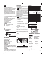
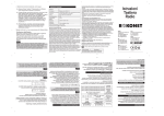
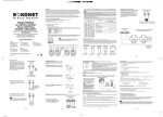
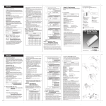
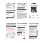
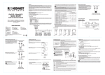
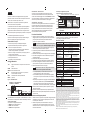
ITALIANO
Introduzione
ShockTec è un rivelatore sismico digitale piezoelettrico per protezioni
perimetrali. Un tentativo di intrusione viene rilevato quando l’intruso tenta di
forzare, forare o manomettere porte, finestre o mura.
ShockTec utilizza un microprocessore per analizzare il segnale della
vibrazione ricevuto dal sensore piezoelettrico.
La caratteristica unica di ShockTec è data dal campionamento digitale del
segnale in due canali separati, ognuno dei quali viene amplificato ad un
guadagno differente. Questa caratteristica fornisce una gamma dinamica
estremamente ampia del segnale campionato, permettendo una misura precisa
e una analisi del segnale della vibrazione più accurata.
ShockTec ha un rivelatore magnetico opzionale per effettuare la doppia
protezione controllando anche l’apertura di porte e finestre.
Caratteristiche Principali
•
•
•
•
•
•
•
•
Cablaggio Morsettiera
-12V+
Ingresso di alimentazione 12 Volt protetto contro l’inversione di
polarità
ALARM
Uscita di allarme NC
TAMPER
Uscita antimanomissione NC
Morsetto da collegare ad una tensione +12V per avere la
memoria di allarme sul rivelatore
REED
SWITCH
Uscita di allarme del contatto porte/finestre NC
(opzionale)
Figura 1: Schema Morsettiera
SENSIBILITA'
ALTA/BASSA
REGOLAZIONE FINE
SENSIBILITA'
J1
LED
TAMPER
MIN
MAX
Schema per il Collegamento di più Unità
Figura 2: Schema per il Collegamento di più Unità
3. Modo Memoria – Primo sensore
Una tensione 12 Volt viene applicata al morsetto LED tramite una resistenza di
47k (fornita) (vedere Figura 2) al fine di inibire il funzionamento del LED
dell’unità. Le operazioni sono le stesse del modo precedente (Qualsiasi
sensore) con la differenza che solo il sensore che ha rilevato per primo
l’allarme farà lampeggiare il LED di colore ARANCIO mentre i sensori
successivi manterranno il LED sempre illuminato.
TAMPER
Procedura di Installazione
1. Scegliere la posizione per l’installazione, assicurarsi che la superficie di
fissaggio sia piana e non presenti irregolarità. Fare riferimento alla tabella 1
per sapere la portata del sensore rispetto ai differenti materiali che
costituiscono la superficie di installazione.
LED
47K
NON utilizzare questa resistenza se si usa il modo Memoria - Qualsiasi Sensore
REED
SWITCH
ALARM
12V
+
Tabella 1: Copertura del sensore tipica in funzione delle diverse superfici
di installazione
Superficie
Raggio
Calcestruzzo Mattoni Metallo Vetro Legno Compensato
1.5m
2.5m
3m
3.5m 3.5m
4m
I valori sopra elencati sono indicativi e devono essere accertati tramite una prova
pratica di copertura per ogni installazione. In alcune condizioni questi valori
possono differire da quelli riportati nella tabella.
Specifiche Tecniche
ShockTec
Gestito da microprocessore per l’analisi digitale del segnale
Regolazione sensibilità tramite potenziometro a doppio stadio
Protezione contro l’apertura del contenitore
LED tricolore che permette una calibrazione accurata e affidabile con
indicazioni di “troppa sensibilità” e “poca sensibilità”
Modello con un doppio contatto reed interno per una doppia protezione
(impatto e contatto porte/finestre)
Il magnete può essere montato su entrambi i lati dell’unità
Sensore piezoelettrico bimorfo
Compatibile con tutte le centrali d’allarme
LED
2. Modo Memoria – Qualsiasi sensore
Una tensione 12 Volt viene applicata al morsetto LED al fine di inibire
il funzionamento del LED dell’unità. Alla rimozione di questa tensione dal
morsetto LED l’unità farà lampeggiare il LED di colore ARANCIO se ha rilevato
una condizione d’allarme in precedenza (memoria di allarme). Riapplicando la
tensione 12V si ripristina la memoria di allarme e il LED si spegne.
REED
SWITCH LED TAMPER
ALARM
- 12V
+
NOTA : Se si sta installando la versione ShockTec con il contatto magnetico,
fare riferimento al paragrafo Installazione del Magnete opzionale.
2. Aprire il sensore svitando il coperchio plastico trasparente con l’apposita
chiave fornita, quindi svitare la vite di blocco coperchio.
3. Con attenzione sganciare la scheda elettronica dalla base facendo leva sulla
linguetta plastica di blocco.
4. Posizionare la base sulla superficie di montaggio e marcare i fori di fissaggio.
5. Se è richiesto il passaggio del cavo dal retro della base aprire l’apposita
predisposizione plastica.
6. Fissare la base sulla superficie scelta per l’installazione .
7. Con attenzione reinserire la scheda elettronica nella base del contenitore.
8. Se è richiesto il passaggio del cavo lateralmente. Passarlo all’interno del
gommino passacavo e completare la connessione elettrica dell’unità.
9. Impostare la sensibilità del sensore come spiegato:
1. Installare ShockTec in una posizione che permetterà il fissaggio del magnete
parallelamente al sensore. Normalmente questa posizione si trova sulla
cornice della porta o della finestra.
2. Installare il magnete sulla parte mobile della finestra o sulla porta, in
corrispondenza di uno dei due lati dello ShockTec, tenendo conto di una
tolleranza di circa 20mm. Posizionare il magnete più vicino possibile e allo
stesso livello dello ShockTec.
7.5mA (14mA max. con LED acceso)
Da -20°C a +60°C
95% senza condensa
Regolazione sensibilità
Potenziometro a doppio stadio
Indicatore LED tricolore
Arancio: Troppo sensibile
Verde: Allarme e Calibrazione corretta
Rosso:
Poco sensibile
Portata contatti a Relé:
Relé di allarme
Relé tamper
Relé magnete reed interno
100mA a 24V—, NC
500mA a 24V—, NC
Non Applicabile
Tempo apertura relé in allarme
100mA a 24V—, NC, Opto relé
500mA at 24VDC, NC
500mA at 24VDC, NC
2.5 secondi
Reed per contatto magnetico
Non Applicabile
Modi Memoria di allarme
Memoria di allarme di “Qualsiasi sensore” o “Primo sensore”
N° max. di unità per loop con
Memoria “Qualsiasi sensore”.
10
Microprocessore con elaborazione digitale del segnale e circuiti di soppressione
rumore ad ampio spettro
Scariche elettrostatiche
Nessun falso allarme fino a scariche di 8 KVolt
40 V/m da 80MHz a 1GHz
Materiale contenitore
ABS ignifugo
Dimensioni contenitore
Come
Due reed interni per posizionare il
magnete da entrambi i lati dell’unità
80
N° max. di unità per loop con
Memoria “Primo sensore”.
Immunità interferenze RF
Installazione del Magnete opzionale
12.5mA (19mA max. con LED acceso)
Umidità massima accettabile
i Con l’unità predisposta per il normale funzionamento, usare uno
strumento appropriato per colpire l’area da proteggere.
ii Se la sensibilità va regolata, usare un piccolo cacciavite per regolare il
trimmer (senso orario per aumentare la sensibilità, senso antiorario per
diminuirla).
iii Ripetere i passi sopra descritti fino a raggiungere la sensibilità desiderata.
Se necessario, è possibile estrarre il ponticello Sensibilità Alta/Bassa
posizionato sul circuito stampato per ridurre la gamma di sensibilità
(Alta sensibilità – ponticello inserito, Bassa sensibilità – ponticello estratto).
Il LED dello ShockTec ha tre modi operativi. I contatti di allarme NC non restano
mai memorizzati in tutti i modi operativi. In allarme il relé si attiva per 2.5 secondi.
Da 9V— a 16V—
Temperatura di funzionamento
Protezione contro gli allarmi
impropri
Modi Operativi dell’indicatore LED
1. Modo Operativo Normale
Al morsetto LED non è applicata alcuna tensione.
• VERDE indica una condizione di allarme.
• ROSSO: Indica “Poca Sensibilità”.
• ARANCIO: Indica “Troppa Sensibilità”.
Assorbimento in corrente
NOTA : Al morsetto LED non deve essere collegata nessuna tensione +
12V durante la fase di regolazione della sensibilità.
10. Chiudere il contenitore del sensore (inserendo il passacavo in gomma) e
serrare la vite di chiusura.
11. Controllare nuovamente la risposta del sensore per l’impatto desiderato.
12. Inserire e serrare il coperchio plastico trasparente usando la chiave speciale
fornita con l’unità.
ShockTec con Contatto Magnetico
Tensione di alimentazione
25x28x95mm
25x28x95mm – rivelatore
10x12x58mm – magnete
Ordinare
Codice prodotto
Descrizione
RK600S00000A
ShockTec, rivelatore sismico digitale
RK600SM0000A
ShockTec, rivelatore sismico digitale con contatto magnetico
RK600S0BR00A
ShockTec, rivelatore sismico digitale in contenitore marrone
RK600SMBR00A
ShockTec, rivelatore sismico digitale con contatto magnetico
in contenitore marrone
ROKONET LIMITED WARRANTY
Rokonet Electronics, Ltd. and its subsidiaries and affiliates (“Seller”) warrant its products to be free from defects
in materials and workmanship under normal use for 18 months from the date of production. Because Seller does
not install or connect the product and because the product may be used in conjunction with products not manufactured
by the Seller, Seller can not guarantee the performance of the security system which uses this product. Seller’s
obligation and liability under this warranty is expressly limited to repairing and replacing, at Seller’s option, within
a reasonable time after the date of delivery, any product not meeting the specifications. Seller makes no other
warranty, expressed or implied, and makes no warranty of merchantability or of fitness for any particular purpose.
In no case shall seller be liable for any consequential or incidental damages for breach of this or any other warranty,
expressed or implied, or upon any other basis of liability whatsoever.
Seller’s obligation under this warranty shall not include any transportation charges or costs of installation or any
liability for direct, indirect, or consequential damages or delay.
Seller does not represent that its product may not be compromised or circumvented; that the product will prevent
any persona; injury or property loss by burglary, robbery, fire or otherwise; or that the product will in all cases
provide adequate warning or protection. Buyer understands that a properly installed and maintained alarm may
only reduce the risk of burglary, robbery or fire without warning, but is not insurance or a guaranty That such will not occur or that
there will be no personal injury or property loss as a result.
Consequently seller shall have no liability for any personal injury, property damage or other loss based on a claim that the product
fails to give warning. However, if seller is held liable, whether directly or indirectly, for any loss or damage arising from under this
limited warranty or otherwise, regardless of cause
or origin, seller’s maximum liability shall not exceed the purchase price of the product, which shall be complete and exclusive
remedy against seller.
No employee or representative of Seller is authorized to change this warranty in any way or grant any other warranty.
WARNING: This product should be tested at least once a week.
Installation Procedure
ENGLISH
Introduction
ShockTec digital shock detectors provide reliable 24-hour
perimeter protection. A break-in is detected as soon as the intruder attempts to
force, smash, drill or even saw through the protected window, door, wall or roof.
The ShockTec employs an advanced digital microprocessor to analyze the
vibration signal received from the piezo electric sensor.
A unique feature of the ShockTec is digital sampling of the signal simultaneously
in two separate channels, each channel amplified at a different gain. This
provides an extremely wide dynamic range of the sampled signal, enabling
precise measurement and analysis of the shock signal.
The ShockTec has optional magnetic reed switches for double protection
on opening windows and doors.
Main Features
• Digital Microprocessor with Intelligent Digital Signal Processing
• Tri-color LED enables accurate and reliable calibration, with “over- sensitive”
and “under-sensitive” indications
• Gross attack detections
• Model with dual internal magnetic reed switches for double protection
(shock and contact)
• Magnet can be mounted on either side of the detector
• Encapsulated bi-morph piezo electric sensor
• Dual stage adjustment potentiometer
• Cover anti-tamper protection
• Compatibility with all makes of control panels
Terminal Wiring
-12V+
ALARM
TAMPER
LED
REED
SWITCH
(optional)
12V power connection, reverse polarity protected
NC Alarm output contact
NC Anti-Tamper contact
Connection for +12V remote latch control signal
NC Door alarm contact
ShockTec
ShockTec with Magnetic Contacts
Supply voltage
9V –16V DC
Current drain
12.5 mA Typical (19 mA Max)
Operational temperature
7.5 mA Typical (14 mA Max)
-20°C to +60°C
Maximum humidity
95% non-condensing
Sensitivity settings
Dual stage potentiometer
Tri-colour LED indicator
Relay contact ratings:
Alarm relay
Tamper relay
Reed relay
Orange: Over-sensitive
Green: Alarm & correct calibration
Red:
Under-sensitive
100mA at 24VDC, NC, Opto relay
500mA at 24VDC, NC
500mA at 24VDC, NC
100mA at 24VDC, NC
500mA at 24VDC, NC
N/A
Time relay open in alarm
2.5 seconds
Magnetic contact reed relay
option
Two reed relays enable locating the
magnet on either side of the detector
N/ A
Latching modes
Any or 1st to latch operation modes
Max no. of units on Any Latch
loop
80
Max no. of units on 1st to
Latch loop
False alarm protection
10
Digital microprocessor signal processing and noise reduction circuits with
maximum ground plane
Electrostatic discharge
No false alarms up to 8kV
RF immunity
40 V/m from 80MHz to 1GHz
Enclosure material
Flame retardant ABS
Enclosure dimensions
25x28x95mm
25x28x95mm – detector
10x12x58mm – magnet
Ordering Information
Part number
Description
RK600S00000A
ShockTec Digital Shock Detector
RK600SM0000A
ShockTec Digital Shock Detector and Magnetic Contact
RK600S0BR00A
ShockTec Digital Shock Detector - Brown
RK600SMBR00A
ShockTec Digital Shock Detector and Magnetic Contact - Brown
Considerations for Optional Magnet Installation
1. Install the ShockTec in a place that will enable you to install the magnet in
parallel to it. Generally, this position would be on the frame of the opening to
be protected, for example, a door frame.
2. Install the magnet on either side of the ShockTec, within 20mm of one of the
sides on the moving section of the opening being protected, for example, a
door. Place the magnet as close as possible to the same level as the face
of ShockTec.
Figure 1: Terminal Connections Diagram
HIGH / LOW
SENSITIVITY
SENSITIVITY
ADJUSTMENT
J1
LED
TAMPER
Technical Data
1. Select the intended position for installation, ensuring the surface is clean
and clear of any irregularities. Refer to Table 1 for details about detection
ranges for the different surface types.
NOTE : If you are installing the ShockTec with Magnetic Contact, refer to the
Considerations for Optional Magnet Installation section.
2. Remove the cover of the detector by unscrewing the lens using the special
key supplied, and then unscrewing the single captive screw, until the cover
is easily removed from the base.
3. Carefully lift the printed circuit board from the base by releasing the
restraining catch.
4. Place the base on the mounting position and mark the desired fixing holes.
5. If rear cable entry is required, thread the cables through the rear of the base
by removing the appropriate knockout.
6. Fix the base in position.
7. Carefully clip the printed circuit onto the base.
8. If side cable entry is required, draw the cable through the rubber grommet
and complete the electrical connection.
9. Set the detector’s sensitivity as follows:
NOTE : The LED terminal should not be supplied with 12V voltage
during the sensitivity test.
i With the unit set for normal operation, use a suitable instrument to bang
or tap the protected area.
ii If the sensitivity needs adjustment, use a screwdriver to adjust the
trimmer (turn the trimmer control clockwise to increase sensitivity or
counter-clockwise to reduce sensitivity).
iii Repeat steps i and ii until the desired sensitivity level is achieved. If
required, you can remove the High/Low Sensitivity jumper on the circuit
board to reduce sensitivity range (High sensitivity – jumper shorted, Low
sensitivity – jumper removed).
10. Replace the cover of the sensor (including the rubber grommet) and tighten
the captive screw.
11. Recheck the detector’s response to the desired impact.
12. Insert and screw the lens into the cover using the special key supplied for
this purpose.
MIN
MAX
REED
SWITCH LED TAMPER
ALARM
- 12V
+
Installation Instructions
Multiple Unit Connection Procedure
ROKONET ELECTRONICS LTD.
14 HACHOMA ST.
75655 RISHON LETZION. ISRAEL.
TEL: (972) 3 963 7777
FAX: (972) 3 961 6584
Email: [email protected]
Figure 2: Multiple Unit Connection Procedure
Modes of LED Indication
The LED of the ShockTec has three operational modes. The NC alarm contacts
are non-latching in all modes of operation. On alarm activation, the alarm
contacts open the circuit for 2.5 seconds.
1. Normal Operational Mode
No voltage is applied to the LED Terminal. The LED illuminates while the
ALARM contact is open in response to an input signal.
• GREEN indicates an alarm condition.
• RED: Under -Sensitive indication.
• ORANGE: Over-Sensitive indication.
2. Any to Latch Mode
12V is applied to the LED terminal causing it to be inhibited. Upon
removal of the 12V, the detector switches to a Normal Operation Mode and a
continuously flashing ORANGE LED indicates if an alarm is detected (Alarm
memory). Reapplication of 12V resets the latch (Alarm memory) and
extinguishes the LED.
3. First to Latch Mode
12V is applied to the LED terminal via a 47k resistor (see Figure 2) causing it
to be inhibited. Operation is the same as in Any to Latch Mode with the
exception that only the first detector to detect an alarm is indicated by a
continuous flashing Orange LED, whereas any subsequent detector is
indicated by a steady Orange LED.
12V TO
LED
47K
DO NOT use a resistor when using “Any To Latch” Mode
REED
SWITCH
ROKONET USA:
TEL: 1 305 592 3820
FAX: 1 305 592 3825
Email: [email protected]
TAMPER
ALARM
12V
+
Table 1: Typical Detection Range
Surface
Radius
Concrete
1.5m
Brick Wall
2.5m
Steel
3m
Glass Wood
3.5m 3.5m
Plywood
4m
The above values are typical and are subject to practical testing, which must
be performed for each installation. In some environments, these values may
differ from the values listed above.
ROKONET UK:
TEL: 44 (0)1527 576 765
FAX: 44 (0)1527 576 816
Email: [email protected]
ROKONET ITALY:
TEL: 39 (02)3925 354
FAX: 39 (02)3925 131
Email: [email protected]
ROKONET BRAZIL:
TEL: 55 (11)3661 8767
FAX: 55 (11)3661 7783
Email: [email protected]
ROKONET SPAIN:
TEL: 34 (91)4902133
FAX: 34 (91)4902134
Email: [email protected]
© Rokonet Electronics Ltd.
5IN600S
03/05