1
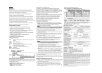
Introduction
ProSYS is a modular integrated system that combines access control, security protection, and home automation, with the
advantage of controlling the whole system through one interface.
ProSYS is available in three models that use the same accessories, but have different maximum capabilities (ProSYS 128,
ProSYS 40, ProSYS 16) . Through its 4-wire BUS, it can support a variety of optional modules, including multiple Keypads,
Zone Expanders, a Wireless Interface, supplemental Power Supplies, a Voice module, capabilities for Access Control, an
X-10 Interface, Event Log, and Utility Outputs. All these devices communicate with the system by sending commands and
data over the BUS, which originates at the Main Panel.
R I S C O
G R O U P
ProSYS / WaveSYS*
QUICK START
INSTRUCTIONS GUIDE
(For full comprehensive instructions refer
to the ProSYS Installer Manual 5IN128IM)
We recommend reading and fully understanding the ProSYS Installation manual and User’s manual before any installation
of the system is carried out. The Quick Start Instructions guide is intended for those who have experience in installing Rokonet
security panels. For additional information refer to the ProSYS Installer Manual (p/n 5IN128IM).
STEP 1: Mounting the Main Panel
Consideration in locating the fixing of the main panel should be given to:
● Dry place near an AC power supply (switched off).
● With a good earth connection.
● With access to the customer's phone lines.
● Access for the routing of cables for the system from detection devices.
When connecting the Power Supply Module do NOT make any connection to the AUX (RED) terminal from the Main
Panel. It is used for the outgoing BUS to supply voltage to other modules. The module supplies power to all modules
and/or keypads located AFTER the point that it is connected to the BUS.
Notes:
In the ProSYS 16 and the ProSYS 40, there is only one BUS, which can be connected to the BUS 1 terminal block
or to one of the two BUS 1 plugs (J1 and J5).
In the ProSYS 128, there is also a BUS 2, which is separate from BUS 1. You can connect to the BUS 2 terminal
block or to the BUS 2 plug (J8). In addition, if one of the BUSes is shorted or there is any kind of problem that
interrupts the BUS data, the other one will continue to operate normally.
3. Wiring Auxiliary Devices
The main panel has 2 aux terminals. Use the Auxiliary Power
AUX (+) COM (-) terminals to power PIRs, glass-break detectors
(4-wire types), smoke detectors, audio switches, photoelectric
systems and/or any device that requires a 12V DC power supply.
The total power from the AUX terminals should not exceed
600mA.
If the auxiliary outputs are overloaded (exceed 600mA) and
are shut down, you must disconnect all loads from the outputs
for a period of at least 10 seconds before you reconnect any
load to the auxiliary outputs.
B: Defining Modules ID number
Each accessory has its ID category number, which is defined by dipswitches. ID numbers are defined per category
and the first module in each category is defined as ID=1. Before setting power on, define each module’s ID number
by setting the dipswitches as follows:
ID
01
02
03
04
05
06
07
08
09
10
11
12
13
14
15
16
STEP 2: Wiring the Main Panel
1. BUS Connection
A: Wiring External Modules
The set of four terminals on the left of the Main Panel represents the Expansion BUS. These support the connection
of keypads and expansion modules. The connections are terminal-to-terminal with color-coded wires, as follows:
BUS Terminal
Description
AUX RED
+12V power
COM BLK
Black 0V common
BUS YEL
Yellow DATA
BUS GRN
Green DATA
The parallel wiring system supports parallel connections from any point along the wiring. The maximum wire run
permitted is 300 meters (1000 feet) for all legs of the BUS. To prevent a possible drop in voltage due to multiple
keypads and long wire runs, use a quality 4-conductor cable with an appropriate gauge size.
1
OFF
ON
OFF
ON
OFF
ON
OFF
ON
OFF
ON
OFF
ON
OFF
ON
OFF
ON
Dipswitches
2
3
OFF
OFF
OFF
OFF
ON
OFF
ON
OFF
OFF
ON
OFF
ON
ON
ON
ON
ON
OFF
OFF
OFF
OFF
ON
OFF
ON
OFF
OFF
ON
OFF
ON
ON
ON
ON
ON
4
OFF
OFF
OFF
OFF
OFF
OFF
OFF
OFF
ON
ON
ON
ON
ON
ON
ON
ON
Modules ID Range
Category
PROSYS MAIN PANEL
AUX
COM
Auxiliary device as: PIR,Glass
break detector , Audio switch ...
ProSYS 16 ProSYS 40 ProSYS 128
Zone Expanders (include wireless)
1
1-4
1-8
Keypads
1-8
1-12
1-16
Output Modules
1-2
1-4
1-8
Supervised Power Supply
1-8
1-8
1-8
Access Control Modules
1-2
1-4
1-8
Memory Expansion
ID=1
ID=1
(512 events) (512 or 999)
Digital Key Readers
1-16
1-16
1-16
Voice Module
1
1
1
Wireless Key Buttons
1
1-4
1-4
PROSYS MAIN PANEL
Z
COM
TYPICAL FIRE ZONE WIRING
(Two 4 wire smoke detectors)
UO AUX
+IN
+OUT
+IN
+OUT
Control Panel
Bus Connectors
www.rokonet.com
USA
Rokonet Industries, Inc.
Tel: +1-305-592-3820
Fax: +1-305-592-3825
Toll Free: 1-800-344-2025
e-mail: [email protected]
ITALY
Rokonet Electronics SRL
Tel: +39-02-392-5354
Fax:: +39-02-392-5131
e-mail: [email protected]
BRAZIL
Rokonet Brasil Ltda.
Tel: +55-21-2496.3544
Fax:: +55-21-2496.3547
e-mail:[email protected]
2. Zone Inputs Connection
To connect a hardwired zone use a 4-conductor cable wiring.
Connect each zone to the appropriate Zone (Z) terminal and its related COM terminal. Each pair of zones shares a
COM terminal. It is recommended that you use an End-of-Line Resistor at the far end of each hardwired zone to prevent
short-circuits (16 resistors are supplied). For a zone with a tamper switch, you can use a Double End-of-Line Resistor
to save additional Main Panel connections
BUS
YEL GRN
UK
Rokonet U.K. Ltd.
Tel: +44-1527-576-765
Fax: +44-1527-576-816
Free Phone: 0800-269881
e-mail: [email protected]
DATA
DATA
DATA
DATA
0V
0V
BREAK +12V AT
INPUT TO EACH
X POWER
SUPPLY
(KEEP 0V COMMON)
+12V
NORMALLY CLOSED
ZONE CONFIGURATION
zone
+12V
NORMALLY OPEN ZONE
CONFIGURATION
zone
com
com
AUX COM
RED BLK
BUS
YEL GRN
AUX COM
RED BLK
BUS
YEL GRN
AUX COM
RED BLK
Expansion Module Expansion Module
Bus Connectors
Bus Connectors
5IN128IMQ
BUS
YEL GRN
Power Supply
Bus Connectors
AUX COM
RED BLK
zone
END OF LINE ZONE
(N.O CONTACT)
com
BUS
YEL GRN
Expansion Module
Bus Connectors
ALARM
ALARM
DETECTOR
DETECTOR
page 2
4. Bell Sounder Wiring
The Bell/LS terminal determines the output for the bell
or external sounder. When connecting the internal
sounding device pay attention to the polarity.
To avoid Bell Loop Trouble, if NO connection is made
to an internal sounder, use a 2.2KΩ resistor in its place.
It is important to position the BELL/LS Jumper (J3)
correctly. The position varies depending on the type
of internal sounder. A maximum of 900 mA may be
drawn from this terminal.
END OF LINE ZONE
(N.C CONTACT)
zone
com
2.2 K
* WaveSYS Installation & Programming Instructions in this document
are equivalent to ProSYS 40.
PROSYS MAIN PANEL
BELL/LS
+
7. Utility Output Wiring
UO1: Relay output (3 Amps). Usually used for an external
siren connection. Use the J10 jumper located on the main
board to determine the UO1 (behaviour) as follows:
LOUDSPEAKER
(13.8 v, 900 mA MAX)
ALARM
DETECTOR
ALARM
DETECTOR
2.2 K EOL RESISTOR
2.2 K 2.2 K
ALARM
DETECTOR
TAMPER
page 4
◆
2. After a short delay the following display appears:
To Install
Press *
3. Press [*]. The keypad prompts you for the Installer code.
depending on the ProSYS Model:
4. Enter the default Installer Code followed by
● ProSYS 128: [0][1][2][8]
● ProSYS 40: [0][1][4][0]
● ProSYS 16: [0][1][1][6]
5. The system enters the automatic accessories recognition process. Press
6. To exit Installer programming press “0” from the Installer’s main menu.
Position the J2 default jumper on one pin to save data.
PROSYS MAIN PANEL
5. Bell Tamper Wiring
Connect the 230V AC to the mains fuse
input terminal block (N,L). Fasten the AC
cord to the metal box using adjustable
clamps.
Note:
Be sure to connect the live wire of the AC
power through the AC fuse. The size of
the conductors must not be less than
0.75mm2 (18AWG).
Single pin: If the J10 connector is placed only on 1 pin, the
UO1 acts as a dry contact.
2.2 K EOL
RESISTOR
BELL TAMPER
UO2-UO6: Transistor outputs (UO2 — 500 mA, UO3-UO6 70 mA). Connect the positive connection of the device to AUX
(+) and the negative (-) connection to the UO's terminals.
6. Box Tamper Wiring
Connect the box tamper to the BOX TMP and COM
terminals on the Main Panel, as illustrated.
BOX
TMP
COM
Note:
The Box Tamper input provides double protection,
wall and box.
PROSYS MAIN PANEL
Connect the incoming telephone line to the Main
Panel's LINE terminals.
Connect any telephone on the premises to the
SET terminals.
SET
To access the Installer Programming Menu from the regular operation mode: (J2 is on one pin)
1. From the regular (user) operation mode press: [*][7][1]
2. The keypad prompts you for the Installer code.
for accessing the Installer menu.
3. Enter the Installer Code followed by
◆
Reset to default modes
To restore the Main Panel to the manufacturer's defaults:
1. Disconnect all power from the Main Panel.
2. Position the J2 default jumper on both of the J2 pins.
3. Reconnect the power to the main and backup battery to the Main Panel. The keypad sounds a long beep and all
of the LEDs flash once. After 20 seconds the following message is displayed: “To Install Press *”
4. On the Main Panel, reposition the J2 default jumper on one of the J2 pins (where it resides for safekeeping).
5. Remember that the Installer Code has been restored to the manufacturer's default setting.
315 mA
40 VA
L
N
STEP 3: Installer Programming
The ProSYS can be programmed from local or remote Upload/Download software or from the LCD Keypad used as an
interface tool. The following keys are used in the programming procedure. For additional information refer to the Installer
manual.
Key
8. Telephone Line Connection
16.5 VAC
Programming Mode Function
Note:
To enable the restore of the manufacturer's default, the system bit "Default Enable/Disable" (defined in quick key
[1][7] in the main Installer menu) must be defined as Enable.
Use this key to exit the current programming selection and move up to the next higher level in the programming
hierarchy catalog.
LINE
Press either one of these keys to move back and forth through the programming level functions.
These keys also change the position of the flashing cursor. When editing a selection, the cursor moves to
the left or right respectively.
T
R
TIP
RING
Use this key to toggle forward through the programming
choices within a selection.
Use this key to toggle backward through the programming
BOX TAMPER
(N.C)
choices within a selection.
Use this key to enter selected information into the system or to accept the current selection and access the
TO TELEPHONE
LINE
page 5
page 6
to acknowledge each module.
7.
◆
FUSE
A C
Initial Setting
1. When defaulting the panel (position J2 on both pins and then power on the system) you enter the installer Programming
menu and the Auto Install feature (Automatic Module recognition). The first display will be:
ROKONET
Please Wait...
Connecting to ground must be performed according to the local National Electrical Code.
11.Main Power Connection
COM
ALRM -OUT
CONTACT
com
zone
10. Ground Connection
Connect the metal box and the door of the metal box to main earth (ground).
Note:
Negative (NEG): When the J10 connector is placed on NEG,
the C terminal on UO1 supplies COM.
BELL
TMP
-IN
DOUBLE END OF LINE
ZONE CONFIGURATION
9. Setting Jumpers
Use the following table to position the jumpers located on the ProSYS main board
Jumper Jumper Description Jumper Operation
J2
Default jumper
For regular operation position the default jumper over one of the J2
connector pins for safekeeping. To default the system position the jumper over the 2 pins
J3
Bell/Loudspeaker
Set this jumper according to the type of siren connected to the system
(bell or loudspeaker)
J4
SIG IN
Connect to the voice module p/n RP200VC
J6
Voice Connector
This connector transmits signals from the Advanced Digital Voice module to the telephone
line during remote communication, and is essential for normal operation of the Digital
Voice module.
J1, J5, J8 are used as quick BUS connectors. Use the 4 pin BUS plugs for easy connection of the BUS Adapter Cable
(RP296EBA) or the Memory Transfer Card.
BELL
Connect the bell tamper to the BELL TMP and COM
terminals on the Main Panel, as illustrated.
ALRM -OUT
CONTACT
page 3
Positive (POS): When the J10 connector is placed on POS,
the C terminal on UO1 supplies 13.8V.
-
-IN
Zone Terminations
2.2 K
ISRAEL
Rokonet Electronics, Ltd.
14 Hachoma st. 75655
Rishon Letzion
Tel: +972-3-961-6555
Fax: +972-3-961-6584
e-mail: [email protected]
www.rokonet.com
AUX COM
RED BLK
lower level of options in the programming hierarchy.
page 7
page 8
INSTALLER PROGRAMMING MENUS
[1]
Quick Key
[1][1]
[1][1][1]
[1][1][1][1]
[1][1][1][2]
[1][1][2]
[1][1][2][1]
[1][1][2][2]
[1][1][3]
[1][1][4]
[1][1][5]
[1][1][6]
[1][1][6][1]
[1][1][6][2]
[1][1][7]
[1][1][7][1]
[1][1][7][2]
[1][1][8]
[1][1][9]
[1][1][9][1]
[1][1][9][2]
[1][2]
[1][2][ 01.. 34]
SYSTEM
Parameter
Default
System: Time Define
Exit Entry Delay 1
Entry Delay 1
30
Exit Delay 1
45
Exit Entry Delay 2
Entry Delay 2
45
Exit Delay 2
60
Bell Time Out
04
Bell Delay
00
Switched Auxiliary Break
10
Wireless Module Times
Jamming Time
None
Supervisory (S.V) Time
0
Zone Test Times
Start Test
HR:00;MIN:00
Zone Test Period
00
AC Off Delay
30
More Times
Phone Line Cut Delay
04
Guard Delay
30
System: System Control
Parameter
Default Parameter
01) Quick Arm
YES 13) Alarm Zone
Expander Cut
02) Quick UO
YES 14) Fire Temporal Alarm
03) Allow Bypass
YES 15) Grand Master Code
04) Quick Bypass
NO
16) Audible Jamming
05) False Code
NO
17) Technical Tamper
Trouble
06) Bell Squawk
YES 18) Technical Reset
07) Bell 30/10
NO
19) Abort Alarm
[1][3]
[1][3][1]
[1][3][2]
[1][4]
[1][4][1]
[1][4][2]
[1][4][3]
[1][5]
[1][5][0]
[1][5][ 1..8]
[1][6]
08) Alarm Phone Cut
NO
09) 3 Minutes Bypass
YES
10) Double Verification NO
Fire Alarm
11) Audible Panic
NO
NO
12) Buzzer➔Bell
System: Set Clock
System Date
System Time
System: Windowing
Window Start
Window Stop
Window Days
System: Labels
Global
Partition 1 — Partition 8
System: Tamper Sound
[1][7]
[1][8]
[1][8][1]
[1][8][2]
[1][9]
System: Default Enable
System: Service Information
Service Name
Service Phone
System: System Version
[2]
Quick Key
[2][1]
[2][2]
[2][3]
Range
0-255 sec
0-255 sec
0-255 sec
0-255 sec
01-90 min
00-90 min
01-90 sec
ZONES
Parameter
Options
Zones: One By One
Zones: Partitions
Zones: Zone Type
[2][3][ZZ] + [DISARM] +[00-22] 00) Not Used
01) Exit Entry 1
02) Exit Entry 2
03) Exit (Open)/Entry
04) Entry Follower
05) Instant
06) Interior + Exit Entry 1
07) Interior + Exit Entry 2
08) Interior + Exit (Open)/Entry
None, 10,20,30 sec
0-7 hours
[2][4]
Zones: Zone Sound
[2][4][ZZ] + [DISARM] +[1-6]
00-24 Hours, 00-59 Min
00-24 Hours
0-255 Min
[2][5]
Zones: Zone Termination
[2][5][ZZ] + [DISARM] +[1-4]
Zones: Loop Response
[2][6][ZZ] + [DISARM] +[1-12]
[2][6]
01-20 Min
01-99 Min
Default Parameter
NO 25) Engineer Tamper
NO
NO
NO
NO
NO
NO
20) Summer/Winter Clock
NO
21) Forced Keyswitch Arming YES
22) Pager
NO
23) Arm Pre Warning
24) Low Battery Arm
Default
NO
26) Blank Display
27) 24 Hour Bypass
28) IMQ Install
29) Grand Master
Authority/Partition
30) Double Code
31) Disarm Stop
Follow Me
32) Global Follower
33) Area
34) Disable Keypad when
Auto Disarm exist
YES
YES
JAN 01 2000 (SAT)
00:00
DD MM YYYY (DAY)
HH:MM
HR:00;MIN:00
HR:00;MIN:00
All
00-24 Hours, 00-59 Min
00-24 Hours, 00-59 Min
SUN(Y/N)-SAT(Y/N)
Rokonet
Partition 1 — Partition 8
Bell/Arm Buzzer/Disarm
12 Characters
12 Characters
1) Silent
3) Buzzer Only
5) Bell/Arm
NO
NO
NO
YES
NO
YES
YES
NO
NO
09) Interior + Entry Follower
10) Interior + Instant
11) Utility Output Trigger
12) Day Zone
13) 24 Hours
14) Fire
15) Panic
16) Special Emergency
17) Pulsed Keyswitch
2.The loop response times defined in locations 5 to 12 can be assigned only to zones 1
to 8 on the Main Panel or to zones located on the zone expander RP128EZ8F00A.
1) None
2) Ordered
3) Not Ordered
Zones: Cross Zones
[2][8]
[2][9]
[2][9][1]
[2][9][2]
[2][9][3]
[2][9][4]
[2][9][5]
[2][9][6]
[2][9][7]
[2][9][8]
[2][9][9]
[2][0]
[2][0][1]
[2][0][2]
Zones: Zone Labels
Zones: Maintenance
Copy to a Zone
Delete a Zone
Add/Copy Partition
Delete a Partition
Wireless Module Calibration
Wireless Zone Allocation
Wireless Communication Test
Zone Self Test
Soak Test
Zones: Miscellaneous
Forced Arming
Pulsed Count
[3][1]
Utility Output:
Follow System Event
01) Bell Follow
02) No Telephone Line
03) Communication Failure
04) Trouble Follow
05) Ground Pulse
06) Low Battery
07) Ac Loss Follow
08) Sensors Test
09) Voice Module
10) Battery Test
11) Bell Burglary
12) Scheduler
13) Digital Reader Communication
14) Switched Auxiliary
Utility Output:
Follow Partition Event
01) Ready Follow
02) Alarm follow
03) Arm Follow
04) Burglary Follow
05) Fire Follow
06) Panic Follow
07) Special Emergency Follow
08) Duress Follow
09) Buzzer Follow
10) Chime Follow
11) Exit/Entry Follow
12) Fire Trouble
13) Day zone Trouble
14) General Trouble
[3][2]
[3][3]
Utility Output: Follow Zone
[3][4]
[4]
Quick Key
[4][1]
CODE
Parameter
Code Maintenance:
Authority Level
[4][2]
Code Maintenance:
Partition
Code Maintenance:
Grand Master
Code Maintenance:
Installer
Code Maintenance:
Sub Installer
Code Maintenance:
Code Length
[4][4]
[4][5]
[4][6]
[5]
Quick Key
[5][1]
[5][1][1]
[5][1][2]
[5][1][3]
[5][1][4]
[5][2]
[5][3]
[5][3][1]
[5][3][2]
[5][3][3]
2) Bell Only
4) Bell +Buzzer
6) Buzzer/Disarm
16 Characters
16 Characters
page 9
Options
15) Stay Follow
16) Tamper Follow
17) Disarm Follow
18) Bell Follow
19) Bell Stay Off
20) Zone Bypass
01) Zone Follow
03) Arm Follow
02) Alarm Follow
04) Disarm Follow
Note: Each utility output can be activated by a group of up to five zones.
[5][4]
[5][4][1]
[5][4][2]
[5][4][3]
[5][5]
[5][5] [01..14]
[5][6]
[5][6][1]
[5][6][2]
[5][6][3]
[5][6][4]
Dialer: Access and ID
Access Code
ID Code
MS Lock
Dialer: Controls
Parameter
01 MS Enable
02 Follow Me Enable
03 Upload/Download Enable
04 Call Delay
05 Dial Tone Wait
06 Call Save
07 User Initiated Call
Dialer: Parameters
Monitoring Station Retries
Follow Me Retries
Ring to Upload/Download
Dial Tone Time
[5][6][5]
Redial Wait
30
[5][6][6]
Dialing Method
DTMF
[5][6][7]
Pulse Duty Cycle
61/39
[5][6][8]
[5][7]
[5][7][1]
Swinger Shutdown Limit
Dialer: Report Split
Monitoring Station Arm/Disarm
00
[5][7][2]
Monitoring Station Urgent
1s1 Backup 2nd
[5][7][3]
Monitoring Station Non Urgent
1s1 Backup 2nd
[5][7][4]
[5][7][4] [1..8][1]
[5][7][4] [1..8][2]
Follow Me
Phone Partition
Phone Event
Event
01) Intruder
02) Fire
03) Emergency
04) Panic
05) Tamper
06) Remote Programming
07) AC Off
08) Duress
09) Arm
5678
0001
000000
Default
YES
YES
YES
NO
YES
No
YES
Parameter
08 Call Back Upload/Download
09 Auto Batch
10 Answering Machine Override
11 UL Installation
12 Show Kiss Off
13 Show Handshake
14 Audible Kissoff
08
03
12
6
Options
Grand Master
Manager
User
Arm Only
Cleaner
Utility Output Activation
1s1 Backup 2nd
User Unbypass
Guard
1) 4 Digits
2) 6 Digits
DIALER
Parameter
Default
Dialer: Telephone Numbers
MS Phone 1
MS Phone 2
MS Phone 3
Remote Upload/Download Phone
Dialer: Customer Account Number
Dialer: Communication Format
Format for MS Phone 1
Format for MS Phone 2
Format for MS Phone 3
page 10
Range
32 characters
Default
YES
YES
YES
YES
NO
NO
NO
YES
NO
page 11
Default
YES
NO
YES
NO
NO
NO
NO
01-15
01-15
01-15
1) 6 seconds
2) 9 seconds
1) 30 sec
2) 60 sec
1) DTMF
2) Pulse @ 20 BPS
3) Pulse @ 10 BPS
1) 67/33
2) 61/39
00-15
Utility Output: Follow Code
[4][3]
Yes
ProSYS Security
System
UTILITY OUTPUT
Parameter
Utility Output: Follow Nothing
18) Exit Termination
19) Latched Keyswitch
20) Entry Follower + Stay
21) Keyswitch Delay
22) Latched Keyswitch
Delay
1) Silent
4) Bell + Buzzer
2) Bell Only
5) Door Chime
3) Buzzer Only
6) Bell/Arm Buzzer/Disarm
1) Normally Close
3) Double End Of Line
2) End Of Line
4) Normally Open
1) Normal (400 ms)
05) 0.5 Hour
09) 2.5 Hours
2) Slow( 1 sec)
06) 1 Hour
10) 3 Hours
3) Fast (10 ms)
07) 1.5 Hours
11) 3.5 Hours
4) Very Fast (1 ms)
08) 2 Hours
12) 4 Hours
Note:
1.The loop response 1 ms (option 4) is usually used for shutters or other devices that
require very quick responses. This loop response time can be defined only for zones
located on the zone expander RP128EZ8F00A.
[2][7]
[3]
Quick Key
[3][0]
1) Do not call
2) Call 1s1
3) Call 2nd
4) Call 3rd
5) Call All
6) 1s1 Backup 2nd
1) Do not call
2) Call 1s1
3) Call 2nd
4) Call 3rd
5) Call All
6) 1s1 Backup 2nd
1) Do not call
2) Call 1s1
3) Call 2nd
4) Call 3rd
5) Call All
6) 1s1 Backup 2nd
Event
10) Disarm
11) Bypass
12) Wireless lost
13) Wireless Low Battery
14) Bell Trouble
15) False Code
16) Low Battery
17) Wireless Jamming
18) BUS Trouble
Default
NO
NO
NO
NO
NO
NO
NO
NO
NO
page 12
)
[5][7][4][ 1-8][3]
[5][8]
[5][8][1..3]
Phone Restore Events
Event
01) Intruder
02) Tamper
03) AC Off
04) Wireless lost
05) Wireless Low Battery
Dialer: Alarm Restore
Alarm Restore
[5][9]
[5][9][1]
[5][9][2]
[5][0]
[5][0][1]
[5][0][2]
[5][0][3]
Dialer: Periodic test
Monitoring Station Test
Upload Download Test
Dialer: Auto Codes
Contact ID
SIA
Delete All
[6]
Quick Key
[6][1]
[6][1][1][1..4]
[6][1][2][1..4]
[6][2][1..9]
REPORT CODES
Parameter
Report Codes: Emergency Key
Emergency Key Alarm
Emergency Key Alarm Restore
Report Codes: Zones
Default
YES
NO
NO
NO
NO
On Bell Time out
[6][4]
[6][4][1][1..0]
[6][4][2][1..0]
[6][5]
[6][5][1][1..4]
[6][5][2][1..4]
[6][6]
[6][6][1..7]
Report Codes: Accessory Tamper
Report Codes: Main Trouble
Main Trouble
Main Trouble Restore
Report Codes: Power
Supply Module Trouble
Trouble Condition
Trouble Condition Restore
Report Codes: Arm Codes
Arm Codes
Default
NO
NO
NO
NO
1) On Bell Time put
2) Follow Zone
3) At Disarm
[6][8]
[6][8][1..0]
[6][9]
[6][0]
[6][0][1..4]
[7]
Quick Key
[7][1]
[7][1][1..9]
Report Codes: Disarm Codes
Disarm Codes
Report Codes: Miscellaneous
Miscellaneous
Report Codes:
Special communication
Report Codes: Accessory Code
Accessory Code
1)
2)
1)
2)
1)
2)
3)
3)
4)
3)
4)
5)
6)
7)
8)
9)
1)
2)
3)
4)
Auxiliary Emergency
Panic
Auxiliary Emergency
Panic
Alarm
Alarm Restore
Day zone Trouble/ Wireless
Zone Supervision
Day zone Trouble/ Wireless
Zone Supervision Restore
Keypad
Utility Output
Power Supply
Event Logger
[7][2]
[7][3]
[7][4]
[7][5]
Accessories: Verify Module
Accessories: Bus Test
Accessories: Bus Scan
Accessories: Auto Settings
[8]
[8][1]
5) Wireless Button Accessory
6) Wireless Zone Module
7) Advanced Voice Module
[8][2]
MISCELLANEOUS
Miscellaneous:
Wireless Button Parameters
Miscellaneous:
Wireless Button Allocation
1)
2)
3)
4)
5)
1)
2)
3)
4)
5)
Low Battery
Bell
Phone
AC Loss
Aux Fail
Low Battery
Bell
Phone
AC Loss
Aux Fail
6)
7)
8)
9)
0)
6)
7)
8)
9)
0)
[9]
Quick Key
[9][1]
[9][1][1]
[9][1][2]
[9][1][2][1]
[9][1][2][2]
[9][1][2][3]
[9][1][3]
[9][1][4]
[9][1][4][1]
[9][1][4][2]
[9][1][5]
[9][2]
[9][3]
[9][3][1]
Clock Not Set
BUS Fail
False Code
Bell Tamper
Box Tamper
Clock Not Set
BUS Fail
False Code
Bell Tamper
Box Tamper
1)
2)
1)
2)
Low Battery
Bell
Low Battery
Bell
3)
4)
3)
4)
1)
2)
3)
4)
User Arm
Keyswitch Arm
Auto Armed
Remote Arm
5) Quick Arm
6) Force Arm
7) Wireless Button Arm
page 13
AC Loss
AUX Fail
AC Loss
AUX Fail
[0]
ACCESS CONTROL
Parameter
Door Define
Partitions
Door Time Setting
Open Delay
Door Force Delay
Door Alarm Delay
Door Fire Settings
Door Input Settings
Door contact
Request to Exit Button
Door Label
Card Code Position
Special Code
Arm Code
Quick Arm Code
4) Remote Disarm
5) Wireless Button Disarm
1)
2)
3)
4)
5)
6) System Reset
7) Abort Alarm
8) Self Test O.K
9) Self Test Failure
10) Cancel Report
Enter Programming
Exit Programming
Periodic MS Test
Periodic UD Test
Call Back Request
3) Wireless Button Battery
4) Printer Module
Wiring information:
Use the following tables for selecting the correct wire thickness to minimize the power loss and ensure reliable system
operation. Take into account the installations current requirements and the wiring distances involved
Wire Gauge
24 AWG
22 AWG
20 AWG
19 AWG
Options
1) Keypad
2) Zone Expander
3) Utility Output
4) Power Supply
5) Event Log
6) Wireless Button
7) Printer Module
8) Access Control
91) Digital Key Reader
92) Advanced Digital Voice Module
(0.5 mm / 0.02inch)
(0.64mm / 0.025inch)
(0.8 mm / 0.031inch)
(0.9 mm / 0.035inch)
Max Combined Length (BUS) from Panel to Expansion module
150 meters
492 feet
200 meters
656 feet
333 meters
1092 feet
400 meters
1312 feet
Desired Wire Gauge for Detectors Wiring Distances
Max
Current
(mA)
ACCESSORIES
Parameter
Accessories: Add/Delete Module
Add/Delete Module
Fire
Duress
Fire
Duress
Bypass
Zone Tamper
Zone Tamper Restore
Low Battery
Low Battery Restore
1) User Disarm
2) Keyswitch Disarm
3) Auto Disarm
1) Wireless Zone Expander
2) Wireless Button Module
Options
4)
[6][3][1..7]
Event
06) Bell Trouble
07) Low Battery
08) Wireless Jamming
09) BUS Trouble
[6][7]
[6][7][1..5]
20mA
30mA
40mA
50mA
60mA
70mA
80mA
90mA
100mA
18 AWG
(1.00mm / 0.04inch)
19 AWG
(0.9 mm / 0.035inch)
Max Run
Meters
Feet
1195
3920
793
2600
597
1960
478
1568
296
1300
341
1120
299
980
264
867
239
784
Max Run
Meters
Feet
945
3100
628
2060
472
1550
378
1240
314
1030
270
886
237
775
209
687
189
620
20 AWG
22 AWG
(0.8 mm / 0.031inch) (0.64 mm/ 0.025inch)
Max Run
Meters
Feet
750
2460
500
1640
375
1230
300
984
250
820
214
703
187
615
166
547
123
492
Max Run
Meters
Feet
472
1550
314
1030
236
775
189
620
157
515
135
443
118
388
105
343
94
310
24 AWG
(0.5 mm / 0.02inch)
Max Run
Meters
Feet
296
970
197
646
148
485
118
388
98
323
84
277
74
243
66
215
59
194
Main Panel Technical Data:
Default
Range
4
NO
10
Open
1-99 sec
YES/NO
1-99 sec
Open/Close
N.O
N.O
N.O/N.C
N.O/N.C
00
00-37
99
98
00-99
00-99
Input Power
Current Consumption
Rechargeable Standby Battery
Power Outputs:
Auxiliary Power
Bell/LS (External) Sounder Output
16.5 Volts AC @ 40 Volt-Amps (VA) (via integral transformer)
60 mA, typical / 70 mA, maximum
12 Volts up to 17 Amp-Hours (AH), typical
Programmable Voltage (Utility) Output
UO1: Relay (programmable output) (3 Amps)
UO2: 500 mA transistor
UO3-UO6: Open Collector, 70 mA, maximum
375 mm x 330 mm x 98 mm
200 mm x 115 mm x 65 mm
F3
3.0 A
Battery Power
AUX
Automatic fuse
BELL
Automatic fuse
Cabinet Dimensions
Main Board Dimensions
Fuses
12 Volts DC @ 600 mA, maximum (from all AUX terminals)
12 Volts DC @ 900 mA, maximum
Technical Data of Expansion Modules:
Module
8 LED Keypad
16 LED Keypad
LCD Keypad
Proximity LCD
Keypad
8 zone expansion
module
16 zone expansion
module
8,16 wireless zone
expansion module
4 relay output
expansion module
8 transistor output
expansion module
Power Supply
Expansion Module
Current Consumption
32 mA, typical /
72 mA maximum
32 mA, typical /
72 mA maximum
75 mA maximum
100 mA maximum
25 mA, typical /
30 mA, maximum
27 mA, typical /
34 mA, maximum
12 mA, typical /
15 mA, maximum
25 mA, typical /
140 mA, maximum
25 mA, typical /
30 mA, maximum
Additional Information
Frequency: 868.6-868.7 MHz (narrowband operation in EU)
Receiving Range: 200 m (Key fob) - 400 m (detectors)
Contacts: 4 Form C (SPDT) Relays.
Contact rating: 3 A / 24V DC
Contacts: Open Collector, Active Pull-Down, 70 mA maximum
Input Power:
Rechargeable
Standby Battery:
Power Outputs:
Fuses:
Event Log
Expansion Module
Printer Module
X-10 Transmitter
Module
Access Control
Module
Voice Module
Electronic Key
Reader
Advance Digital
Voice Module
Voice Message Unit
25 mA, typical / X
30 mA, maximum
7 mA, typical /
10 mA, maximum
25 mA, typical /
29 mA, maximum
100 mA maximum
Input power
Readers
Consumption
Relay
6 mA, typical/
26 mA maximum
11 mA, typical /
17 mA maximum
38 mA, typical /
Audio Signal
57 mA maximum
9 mA (standby) /
Audio Signal
60 mA (active speaking normal volume) /
130 mA (active speaking full volume)
12 Volts up to 17 Amp-Hours (AH), typical
Auxiliary power: 12 Volts DC @ 600 mA, maximum
Bell/LS (External) Sounder Output: 12 Volts DC @
900 mA, maximum
F1: Battery power 3.0 A
F2: Auxiliary power 2.0 A
F3: Bell/loudspeaker power 1.0 A
13.8V DC + 10%
5V / 150 mA maximum
24V DC / 1 A maximum
Max = 5V pp / Max = 2V
V in max = 2.5V pp / V out max = 4V pp
RTTE COMPLIANCE STATEMENT
Hereby, Rokonet Electronics Ltd, declares that this control panel (RP128MC0000A, RP140MC0000A, RP116MC0000A),
with wired accessories (including cables) and wireless accessories, is in compliance with the essential requirements and
other relevant provisions of Directive 1999/5/EC.
EXIT PROGRAMMING
page 14
16.5 Volts AC @ 40 VA (via transformer)
page 15
page 16