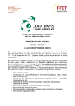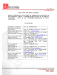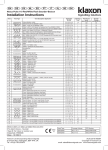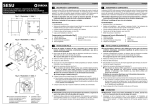
1
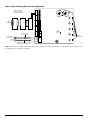
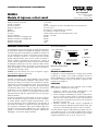
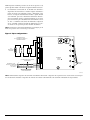
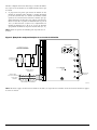
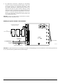
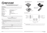
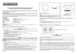
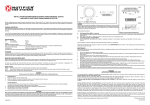
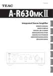
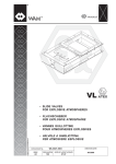
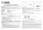
by Honeywell
MI-IM10
Ten Input Monitor Module
Morley IAS Fire Systems
Charles Avenue,
Burgess Hill, West Sussex, RH15 9U
SPECIFICATIONS
Normal Operating Voltage:
Stand-By Current:
Alarm Current:
Temperature Range:
Humidity:
Dimensions:
Accessories:
Wire Gauge:
Maximum SLC Wiring Resistance:
Maximum IDC Wiring Resistance:
Maximum IDC Voltage:
Maximum IDC Current:
15-32 VDC
3.5 mA
60 mA (assumes all ten LEDs solid on)
–10°C to 55°C
10 to 93% Non-condensing
17.3cm H x 14.7cm W x 3.2cm D
Suitably grounded metallic cabinet
0.9mm2 - 3.25mm2
40 Ohms
40 Ohms
12 VDC
1 mA
BEFORE INSTALLING
COMPATIBILITY REQUIREMENTS
This information is included as a quick reference installation
guide. Refer to the appropriate control panel installation manual
for detailed system information. If the modules will be installed in
an existing operational system, inform the operator and local authority that the system will be temporarily out of service. Disconnect the power to the control panel before installing the modules.
This system contains static sensitive components. Always ground
yourself with a proper wrist strap before handling any circuits so
that static charges are removed from the body. The housing cabinet should be metallic and suitably grounded.
To ensure proper operation, this module shall be connected to a
listed compatible system control panel.
The MI-IM10 Module shall be mounted in a suitably grounded
Metallic Cabinet for EMC compliance.
WIRING
NOTE: All wiring must conform to applicable local codes, ordinances, and regulations.
1.Install module wiring in accordance with the job drawings
and appropriate wiring diagrams.
2.All wiring to the MI-IM10 is done via terminal blocks. In order
to properly make electrical connections strip approximately .6
cm of insulation from the end of wire, sliding the bare end of
the wire under the clamping plate screw.
3.Set the address on the modules per the job drawing. Use the
rotary code switches to set the address of the first module
(between 01 and 90).
NOTICE: This manual should be left with the owner/user of
this equipment.
GENERAL DESCRIPTION
The MI-IM10 Ten Input Monitor Module is intended for use in an
intelligent alarm system. Each monitor module is intended to interface between a control panel and normally open contact devices,
such as pull stations. A common SLC input is used for all modules,
and the initiating device loops share a common supervisory supply
and ground. Otherwise, each monitor operates independently from
the others. Each module has its own unique address.
The remaining modules are automatically assigned to the next
nine higher addresses. For example, if the base address switch is
set to 28, the next nine modules will be addressed to 29, 30, 31,
32, 33, 34, 35, 36, and 37.
A pair of rotary code switches is used to set the address of the
first module from 01 to 90. The remaining modules are automatically assigned to the next nine higher addresses. Provisions are
included for disabling a maximum of two unused modules to release the addresses to be used elsewhere. Each module also has
panel controlled green LED indicators. The panel can cause the
LEDs to blink, latch on, or latch off.
DO NOT set the lowest address above 90, as the other modules
will be assigned to nonexistent addresses.
4.A shunt is provided to disable a maximum of two unused
modules. Modules are disabled from the highest address and
work downward. If two modules are disabled, the lowest
eight addresses will be functional, while the highest two will
be disabled. For example, if the shunt for Address Disable is
placed on “two” and the base switch is set to 28, the modules
will be assigned to 28, 29, 30, 31, 32, 33, 34 and 35 while
disabling the highest two positions.
Included:
(6) 1 × 4 Terminal Blocks
(2) 3.2 cm Stand offs
(2) Nuts
NOTE: Place unused shunts on single pin to store on board for future use.
(3) Small Shunts
(4) Screws
(10) 47k Ohm End of Line Resistors
Shipped on Board:
C0906-00
(1) Shunt
M450-02-000
1
I56-2957-000
I56-2957-000
INSTALLATION AND MAINTENANCE INSTRUCTIONS
ADDRESS
5
4
3
2
10
IDC
+9
+ —
BASE ADDRESS
6789
ADDRESS
IDC
ADDRESS
ADDRESS
IDC
ADDRESS
IDC
+
STATUS
INDICATORS
SLC
+ —
TO NEXT
DEVICE
+
–
+
–
—
FROM PANEL OR
PREVIOUS DEVICE
A/B SLCT
COM LOSS
DISABLE 1
DISABLE 2
—
POWER LIMITED
AND SUPERVISED
+ —
+
+1
+0
CLASS B IDC (TYPICAL)
—
+ —
+
+3
+2
—
+4
+ —
+5
47K
EOL
RESISTOR
6789
5
4
3
2
10
IDC
+
—
+6
+ —
+7
+
—
+8
CONNECT MODULES TO
LISTED COMPATIBLE
CONTROL PANELS ONLY
+
Figure 1. Typical Initiating Device Circuit Configuration:
COMMUNICATION LINE 32 VDC MAX.
TWISTED PAIR IS RECOMMENDED.
C0207-00
NOTE: DO NOT mix fire alarm initiating and supervisory devices on the same initiating device circuit. Install contact closure devices
per manufacturer’s installation instructions.
M450-02-000
2
I56-2957-000
ISTRUZIONI DI INSTALLAZIONE E MANUTENZIONE
by Honeywell
MI-IM10
Modulo di ingresso a dieci canali
Morley IAS Fire Systems
Via Grandi 22
S. Donato Milanese, Milano, Italia
SPECIFICHE
Normale tensione di esercizio:
Corrente in stand-by:
Corrente di allarme:
Range di temperatura:
Umidità:
Dimensioni:
Accessori:
Sezione conduttori: Massima resistenza del cablaggio SLC:
Massima resistenza del cablaggio IDC:
Massima tensione IDC:
Massima corrente IDC:
15 - 32 VDC
3.5 mA
60 mA (a condizione che tutti i dieci LED siano accesi in modo fisso)
da -10°C a 55°C
dal 10 all’93% senza formazione di condensa; A 173 mm x L 147 mm x P 25 mm
cabinet metallico dotato di un’adeguata messa a terra
0.9 mm² - 3.25 mm²
40 ohm
40 ohm
12 VDC
1 mA
Accessori in dotazione:
PRIMA DELL’INSTALLAZIONE
Le informazioni qui riportate fungono da guida all’installazione
di consultazione rapida. Per informazioni dettagliate sul sistema,
consultare il manuale di installazione del pannello di controllo. In
caso di installazione dei moduli in un sistema operativo già funzionante, informare l’operatore e le autorità locali che il sistema
rimarrà temporaneamente fuori servizio. Prima di installare i
moduli, scollegare l’alimentazione del pannello di controllo. Il
sistema contiene componenti sensibili all’elettricità staticà. Prima
di maneggiare qualsiasi tipo di circuito, collegarsi sempre a massa
utilizzando un’apposita fascia che respinge le cariche statiche dal
corpo. È importante che la struttura del cabinet sia metallica e
adeguatamente collegata a massa.
(6) 1 × 4 Morsettiera
(2) Dadi
(3) Derivazione
(4) Viti
(10) Resistori di fine
linea da 47k Ohm
Elementi a bordo scheda:
C0906-00
(1) Derivazione
REQUISITI DI COMPATIBILITÀ
AVVISO: Il presente manuale deve essere consegnato al proprietario/all’utente di questo apparecchio.
Per garantire il corretto funzionamento, collegare questo modulo
al pannello di controllo di un sistema compatibile elencato. Il
modulo MI-IM10 deve essere montato all’interno di un contenitore metallico collegato a massa per incontrare i requisiti di compatibilità elettromagnetica.
DESCRIZIONE GENERALE
Il modulo per monitor a dieci ingressi MI-IM10 è stato progettato
per l’uso in sistemi d’allarme intelligenti. Ogni ingresso è stato
progettato per fungere da interfaccia tra un pannello di controllo
e dispositivi con contatti normalmente aperti, quali postazioni di
allarme comandate con maniglia di trazione. IL modulo utilizza
un tradizionale ingresso SLC e i loop del dispositivo di attivazione
condividono la stessa alimentazione di supervisione e la stessa
messa a terra. In caso contrario, ciascun ingresso funzionerebbe
indipendentemente dagli altri. Ogni modulo possiede un proprio
indirizzo distintivo.
CABLAGGIO
NOTA: l’intero cablaggio deve essere conforme a tutte le normative, ordinanze e disposizioni locali vigenti.
1.Installare il cablaggio del modulo conformemente ai diagrammi di lavoro e ai relativi schemi di cablaggio.
2.L’intero cablaggio del MI-IM10 passa attraverso delle morsettiere. Per eseguire in modo corretto le connessioni elettriche
rimuovere circa 5mm di materiale isolante dall’estremità del
filo e far passare l’estremità scoperta del filo sotto la piastra di
fissaggio e serrarne la vite.
3.Impostare l’indirizzo dei moduli secondo il diagramma di
lavoro. Per impostare l’indirizzo del primo modulo (valore compreso tra 01 e 90) utilizzare gli switch con codice a rotazione.
Per impostare l’indirizzo del primo modulo su un valore compreso
tra 01 e 90, utilizzare la coppia di switch con codice a rotazione.
Ai restanti moduli vengono assegnati automaticamente i nove
successivi indirizzi più alti. La disabilitazione di un massimo di
due moduli non utilizzati è regolata da particolari disposizioni
che consentono di riutilizzare altrove questi indirizzi. Ogni modulo dispone anche di indicatori LED di colore verde controllati dal
pannello. A seconda delle istruzioni del pannello, i LED possono
lampeggiare, essere attivati oppure disattivati.
M450-02-000
(2) Stand offs da 32mm
Ai restanti moduli vengono automaticamente assegnati i nove successivi indirizzi più alti. Se ad esempio l’indirizzo dello switch di
riferimento è impostato su 28, ai nove moduli successivi verranno
assegnati gli indirizzi 29, 30, 31, 32, 33, 34, 35, 36 e 37.
3
I56-2957-000
NON impostare l’indirizzo più basso su un valore superiore a 90,
poiché agli altri moduli verrebbero assegnati indirizzi inesistenti.
4.Per disabilitare un massimo di tre moduli non utilizzati è
disponibile una derivazione. I moduli vengono disabilitati a
partire da quello con l’indirizzo più alto e funzionano verso
il basso. Se vengono disabilitati due moduli, i quattro moduli
con l’indirizzo più basso rimarranno funzionanti mentre i
due con l’indirizzo più alto verranno disabilitati. Se ad esempio la derivazione per la disabilitazione dell’indirizzo si trova
su “due” e l’indirizzo dello switch di riferimento è impostato
su 28, ai moduli verranno assegnati gli indirizzi 28, 29, 30 e
31, mentre le due posizioni più alte verranno disabilitate.
NOTA: Posizionare le derivazioni inutilizzate su un singolo pin in
modo che possano essere conservate per usi futuri.
Figura 1. Tipica configurazione :
IDC
+
+9
+ —
6789
5
4
3
2
10
+
+7
+ —
+6
IDC
—
+
+5
NDIRIZZO
+ —
+4
—
+ —
+
+3
NDIRIZZO
+2
IDC
—
+
INDICATORI
DI STATO
SLC
+ —
AL DISPOSITIVO
SUCCESSIVO
+
–
+
–
—
DAL PANNELLO O DAL
DISPOSITIVO PRECEDENTE
SLZN A/B
PERDITA DI COM.
DISABILITA 1
DISABILITA 2
—
CON LIMITAZIONE DELLA POTENZA
E SUPERVISIONE
+ —
+
+1
NDIRIZZO
+0
IDC
IDC CLASSE B (TIPICO)
6789
5
4
3
2
10
IDC
47K
RESISTORE DI
FINE LINEA
NDIRIZZO
—
+8
NDIRIZZO
INDIRIZZO DI RIFERIMENTO
COLLEGARE I MODULI
SOLO AI PANNELLI DI CONTROLLO
COMPATIBILI ELENCATI
LINEA DI COMUNICAZIONE
MAX. 32 VDC SI CONSIGLIA
UN CAVO TWISTED PAIR.
C0283-00
NOTA: NON installare dispositivi di attivazione dell’allarme antincendio e dispositivi di supervisione nel circuito dello stesso dispositivo di attivazione. Installare i dispositivi di chiusura dei contatti conformemente alle istruzioni di installazione del produttore.
M450-02-000
4
I56-2957-000
INSTRUCCIONES DE INSTALACIÓN Y MANTENIMIENTO
by Honeywell
MI-IM10 Módulo Monitor
con diez circuitos de entrada
Morley IAS Fire Systems
C/Ávila 25
San Sebastián de los Reyes, 28700 Madrid, Espana
ESPECIFICACIONES
Tensión de Funcionamiento Normal:
Corriente en reposo:
Corriente en Alarma:
Rango de temperatura: Humedad: Dimensiones (mm):
Accesorios:
Sección del Cable:
Resistencia máxima del lazo analógico:
Resistencia máxima del lazo del circuito de entrada:
Tensión máxima del circuito de entrada:
Corriente máxima del circuito de entrada:
15-32 VDC
3,5 mA
60 mA (asumiendo que los diez leds están iluminados de forma fija)
de –10°C a 55°C
Del 10 al 93% No condensada
185 (alto) x 147 (ancho) x 25 (fondo)
Cabina metálica conectada adecuadamente a tierra
0,9mm² - 3,25mm²
40 Ohmios
40 Ohmios
12 VDC
1 mA
ANTES DE LA INSTALACIÓN
Piezas incluidas:
Esta información se utiliza como guía rápida para la instalación.
Consulte el manual de instalación correspondiente al panel de
control para obtener información detallada sobre el sistema. Si los
módulos se van a instalar en un sistema operativo ya existente,
informe al usuario y a la autoridad local de que dicho sistema estará temporalmente fuera de servicio. Desconecte la alimentación
antes de instalar los módulos. Este sistema contiene componentes
sensibles a la electricidad estática. Utilice una pulsera de conexión
a tierra para manipular los circuitos de modo que se eliminen
las cargas estáticas. La carcasa del módulo también debe estar
conectada a tierra.
(6) 1 × 4 Bloques
de terminales
(2) Tuercas
(2) Puentes
(4) Tornillos
(10) Resistencia de fin
de línea de 47k Ohmios
Elementos integrados:
AVISO: Este manual debe permanecer al alcance del propietario/
usuario del equipo.
(1) Puente
C0906-00
COMPATIBILIDAD
DESCRIPCIÓN GENERAL
Para asegurar un funcionamiento adecuado, conecte este módulo
sólo a un panel de control compatible. El MI-IM10 debe montarse
en una cabina metálica conectada ade-cuadamente a tierra para
cumplir con la directiva de compatibilidad electromagnética (CEM)
El Módulo Monitor MI-IM10 ha sido diseñado para su uso en un
sistema de alarma inteligente. Cada módulo sirve para interconectarse con un panel de control y dispositivos de contacto normalmente abierto, como pulsadores manuales. Para todos los módulos
se utiliza una entrada de lazo SLC común, y los bucles de equipos
de iniciación comparten una fuente de alimentación supervisada
y la toma de tierra. De lo contrario, cada monitor funciona independientemente de los otros. Cada módulo tiene su propia dirección. Para configurar la dirección del primer módulo de 01 a 90, se
utiliza el par de selectores rotatorios. Al resto de los módulos se
les asignarán automáticamente las siguientes nueve direcciones
numéricas. Se incluye la posibilidad de desactivar un máximo de
dos módulos no utilizados, cuyas direcciones se pueden liberar
y utilizar en otro lugar. Cada módulo dispone también de leds
indicadores verdes controlados desde el panel. Desde el panel se
puede hacer que estos leds parpadeen, se mantengan iluminados
de forma fija o se apaguen.
M450-02-000
(2) Separadores
de 32mm
CABLEADO
NOTA: Todos los cables deben ajustarse a los códigos, ordenanzas
y regulaciones locales.
1.Instale el cable del módulo según los dibujos y diagramas
correspondientes.
2.Todo el cableado del MI-IM10 se efectúa mediante bloques de
terminales. Efectúe las conexiones eléctricas pelando unos 5
mm del aislante del cable, a continuación, coloque el cable
pelado debajo del tornillo y enrosque el tornillo.
3.Ajuste la dirección en los módulos según el dibujo. Utilice los
selectores rotatorios para configurar la dirección del primer
módulo (entre 01 y 90). Al resto de los módulos se les asignarán automáticamente las nueve direcciones siguientes. Por
ejemplo, si la dirección base se ajusta con el número 28, a los
siguientes nueve módulos se les adjudicarán las direcciones
29, 30, 31, 32, 33, 34, 35, 36 y 37.
5
I56-2957-000
NO debe configurar la dirección más baja por encima del número
90, ya que al resto de módulos se les adjudicarían direcciones que
no existen.
4.Se proporciona un puente para anular un máximo de dos
módulos no utilizados. Estos módulos se anulan empezando
por la dirección más alta. Si se anulan dos módulos, estarán
operativas las ocho direcciones inferiores, mientras que quedarán anuladas las dos más altas. Por ejemplo, para funcionamiento en clase B, si el puente de anular dirección se pone en
“dos” y la dirección base se ajusta a 28, se adjudicarán a los
módulos los números 28, 29, 30, 31, 32, 33, 34 y 35, mientras
que quedarán anuladas las dos posiciones más altas (36, 37).
NOTA: Guarde los puentes no utilizados para un posible uso en el futuro.
+9
— +
DIRECCIÓN
+8
IDC
— +
— +
+7
+6
IDC
— +
+
+5
—
+4
IDC
—
+3
— +
DIRECCIÓN
+2
— +
IDC
+1
— +
DIRECCIÓN
+0
IDC
INDICADORES
DE ESTADO
+ —
—
AL DISPOSITIVO
SIGUIENTE
+
–
+
–
SELECCIÓN A/B
PÉRDIDA COMUNICACIONES
ANULAR 1
ANULAR 2
+
— +
TENSIÓN LIMITADA Y
SUPERVISADA
SLC
CLASE B IDC (TÍPICO)
DESDE EL PANEL
O DISPOSITIVO ANTERIOR
6789
5
4
3
2
10
+
RESISTENCIA
FINAL DE LÍNEA
47K
DIRECCIÓN BASE
6789
5
4
3
2
10
DIRECCIÓN
LOS MÓDULOS SÓLO SE
DEBEN CONECTAR A PANELES
DE CONTROL COMPATIBLES
DIRECCIÓN
Figura 1. Ejemplo de configuración típica de un circuito de iniciación:
LÍNEA DE COMUNICACIONES 32VDC MAX.
SE RECOMIENDA CABLE TRENZADO.
C0284-00
NOTA: NO mezcle equipos de iniciación de alarmas de incendio y de supervisión en el mismo circuito de iniciación. Instale los equipos
de cierre de contacto
M450-02-000
6
©2006 System Sensor I56-2957-000
INSTALLATIONS UND WARTUNGSANLEITUNG
by Honeywell
MI-IM10
Zehn-Eingangsmodul, überwacht
Morley IAS
Berliner strasse 91
40880 Ratingen, Germany
SPEZIFIKATION
Betriebsspannungsbereich:
Ruhestrom:
Alarmstrom:
Temperaturbereich:
Luftfeuchte:
Abmessungen:
Zubehör:
Kabelquerschnitt:
Maximale Ringbus-Anschlussimpedanz:
Maximale IDC Anschluss Impedanz:
Maximale IDC Spannung:
Maximaler IDC Strom :
15-32 VDC
3,5 mA
60 mA (bei 10 dauerleuchtenden LED)
–10°C to 55°C
10 bis 93% ohne Betauung
173 x 147 x 25 (H x B x T in mm)
geerdetes Metallgehäuse
0,9mm2 – 3,25mm²
40 Ohm
40 Ohm
12 VDC
1 mA
Im Lieferumfang enthalten:
VOR DER INSTALLATION
Diese Information dient als Kurzanleitung für die Installation.
(6) 1 × 4 Anschlussklemmen
(2) 32mm Abstandshalter
Wenn Module in bereits betriebsbereite Anlagen eingebaut
werden, informieren Sie die zuständigen Personen und die regionalen Behörden, dass ggfs. die Anlage zeitweise außer Betrieb
genommen wird. Schalten Sie die Zentrale vor dem Beginn der
Installationsarbeiten spannungsfrei. Das System beinhaltet Bauteile mit elektrostatischer Empfindlichkeit. Erden Sie sich vor dem
Umgang mit diesen Baugruppen mit einem geeigneten Erdungsband zur Ableitung der elektrostatischen Energie. Es sollten nur
Metallgehäuse mit geeigneter Erdung verwendet werden.
(2) Muttern
(3) Steckbrücken
(4) Metallschrauben
(10) 47k Ohm Verbinder
für Abschlusswiderstand
Auf der Platine:
HINWEIS: Diese Anleitung sollte dem Betreiber ausgehändigt und
der Anlagendokumentation beigefügt werden.
(1) Steckbrücken
C0906-00
KOMPATIBILITÄT
ALLGEMEINES
Für den ordnungsgemäßen Betrieb muss das Modul an eine geeignete und kompatible Brandmelderzentrale angeschlossen werden.
Das MI-IM10 Modul mit zehn überwachten Eingängen wird in
intelligenten Gefahrenmeldeanlagen eingesetzt. Jedes Modul ist
als Schnittstelle zwischen der Brandmelderzentrale und externen
Schließerkontakten, z.B. Handmeldern oder Alarmkontakten geeignet. Der gemeinsame Ringbus-Eingang wird für alle Module verwendet so dass die Überwachung und das GND Potential für alle
Ringleitungsteilnehmer gleich ist. Die Überwachung funktioniert
unabhängig voneinander. Jedes Modul hat seine eigene, einzigartige Adresse.
Das MI-IM10-Modul sollte für die Erfüllung der EMV-Richtlinie in
einem geeigneten, geerdeten Metallgehäuse montiert werden
VERDRAHTUNG
HINWEIS: Die Verdrahtung muss gemäß den regionalen Auflagen,
Richtlinien und Anforderungen ausgeführt werden.
1.Installieren Sie das Module gemäß den Projektierungszeichnungen und den entsprechenden Anschlussdiagrammen.
2.Die Verdrahtung des MI-IM10 erfolgt über Schraubklemmen.
Entfernen Sie die Isolierung des Kabelendes auf ca. 0,5cm
Länge und schieben Sie das abisolierte blanke Kabelende
unter die Klemmplatte der Schraubklemme und ziehen diese
fest an.
3.Stellen Sie die Moduladresse des ersten Modules (zwischen
01 und 90) gemäß ihren Projektierungsplänen mit den
Drehschaltern ein.
Mit den beiden Drehschaltern wird die Moduladresse von 01
bis 90 eingestellt. Den verbleibenden Modulen werden automatisch immer die nächsten, um die Zahl 9 erhöhten, Adressnummern zugewiesen. Es besteht die Möglichkeit bis max. zwei nicht
benötigte Module abzuschalten und deren Adressbereich für andere Anwendungen frei zu geben. Jedes Modul hat eine, von der
Zentrale gesteuerte grüne LED-Anzeige. Die Zentrale kann die
LED blinkend, folgend ein oder folgend aus ansteuern.
Die verbleibenden Module werden automatisch den nächsten
9 Adressen zugeordnet. Z.B.: Wenn die Startadresse auf 28 eingestellt ist, belegen die anderen 5 Module die Adressen 29 - 37.
Stellen Sie NIEMALS eine Erstadresse über 90 ein, weil dann die
nächsten Module als nicht vorhanden interpretiert werden.
M450-02-000
7
I56-2957-000
4.Die mitgelieferte Steckbrücke ermöglicht die Abschaltung
von max. drei nicht benutzten Modulen. Module werden von
der höchsten Adresse aus absteigend abgeschaltet. Wenn
zwei Module abgeschaltet werden bleiben die unteren vier
Adressen aktiv und die beiden höchsten Adressen werden
deaktiviert. Wird die Steckbrücke zur Adressabschaltung z.B.
in Position “Zwei” gesteckt und eine Erstadresse von 28 eingestellt, so werden die anderen Adressen 28, 29, 30, 31, 32,
33, 34 und 35 zugeordnet, während die beiden höchsten Adressen abgeschaltet werden.
HINWEIS: Stecken Sie nicht benutzte Steckbrücken zur Aufbewahrung auf einen einzelnen Pin auf.
+9
ADRESSE
+ —
+
+7
+ —
+6
IDC
—
+
+5
ADRESSE
+ —
+4
—
+ —
+
+3
ADRESSE
+2
IDC
—
—
ZUSTANDSANZEIGEN
+
+ —
ZUR NÄCHSTEN
BAUGRUPPE
+
–
+
–
RINGBUS
VON DER ZENTRALE
ODER VORHERIGER BAUGRUPPE
A/B AUSWAHL
COM LOSS
ABSCHALTUNG 1
ABSCHALTUNG 2
—
STROMBEGRENZT
UND ÜBERWACHT
+ —
+
+1
ADRESSE
+0
IDC
BETRIEBSART B IDC (TYPISCH)
6789
5
4
3
2
10
IDC
47 K
ABSCHLUSSWIDERSTAND
ADRESSE
—
+8
MODUL ADRESSE
6789
5
4
3
2
10
IDC
MODULE NUR AN ZUGELASSENE
ZENTRALEN ANSCHLIEßEN
+
Abbildung 1. Typischer Anschluss einer Meldelinie:
C0302-00
SIGNALKABEL 32 VDC MAX.
VERDRILLTE ADERN ERFORDERLICH
HINWEIS: Der gemeinsame Betrieb von Alarmgebern und Überwachungbaugruppen auf einer Meldelinie ist nicht zulässig. Installieren
Sie die Schließerkontakte gemäß den Herstelleranweisungen.
M450-02-000
8
©2006 System Sensor I56-2957-000