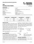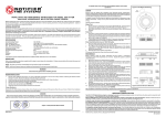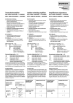
1
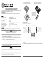
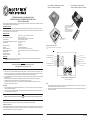
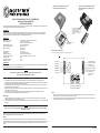
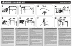
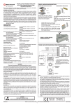
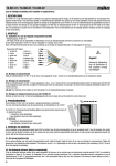
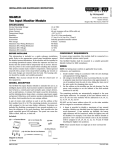
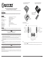
Figure 1a: M701-240 Surface Mount Output
Module with 240V Relay Contacts
Figure 1b: M701-240-DIN Din Rail Mounted
Output Module with 240V Relay Contacts.
INSTALLATION INSTRUCTIONS FOR M701-240 AND M701240-DIN MAINS SWITCHING OUTPUT MODULES
This manual is intended as a quick reference installation guide. Please refer to the control panel manufacturers installation manual for detailed
system information
GENERAL INFORMATION
TO MOUNT, LOCATE LUG OVER TOP OF RAIL
AND ROTATE THE MODULE DOWN TO CLIP
INTO PLACE.
The M700 series of modules are a family of microprocessor controlled interface devices permitting the monitoring and/or control of auxiliary
devices. The M701-240 and M701-240-DIN are output modules, providing 250VAC 5A rated voltage free contacts, both normally open and
normally closed.
TO REMOVE, PUSH UPWARDS, AND ROTATE
TOP OF MODULE AWAY FROM RAIL.
SPECIFICATIONS
Operating Voltage Range
Maximum Standby Current (µA)
Fault Current
Coil Activation/Deactivation Current
Relay Contact Rating
Operating Temperature
Humidity
Dimensions M701-240
Dimensions M701-240-DIN
Weight M701-240
Weight M701-240-DIN
Maximum Wire Gauge
15 to 30VDC (Min 17.5VDC to ensure LED operation)
275µA - No Communication
445µA - Communication w/ blink enabled
8.8mA (Yellow LED illuminated)
76mA Maximum for 12mS
5A, at 30VDC
5A at 250VAC
-20°C to 60°C
5% to 95% Relative Humidity
134mm(H) x 139mm(W) x 40mm(D)
127mm(H) x 76mm(W) x 48mm(D) (Including terminals)
195g
140g
2.5mm²
LOOP CABLE SCREEN
TERMINAL
Figure 2: Module Wiring.
NOTE: WIRING IS THE SAME FOR M701-240 AND M701-240-DIN
INSTALLATION
Relay 1, N/O
Note:
Relay 2, N/C
These modules must only be connected to control panels using compatible proprietary analogue addressable communication protocols
for monitoring and control.
Ground
Ground
CAUTION
Relay 2, N/C
Disconnect loop power before installing modules or sensors.
Relay 1, N/O
High voltages may be present on terminals 7 to 12.
7
8
9
10
11
12
1
2
3
4
5
6
3
2
1
M701-240
1.
2.
3.
4.
The M701-240 includes a custom low profile surface-mounting box with several options for fixing centres. To access all fixing points, and
the rear cable entry knock out, the circuit board must be removed. It is held in place by two screws through the circuit board. Ensure that
these screws are replaced when refitting the circuit board.
If rear cable entry is not required, the box has several cover drill points permitting the entry of cables using suitable glands.
Wiring to the M701-240 is made via two 6 way terminal strips on the module circuit board, capable of supporting conductors up to 2.5mm².
See figure 2 for connections.
An earthing terminal is provided in the surface mount box for connection of the loop cable screen, if used, to ensure continuity. See figure 1a.
2.
5
0 9
3
6
7 2
1
8
TENS
Loop +, Out - See Note 1
Loop -, In
Loop +, In
Loop +, Out - See Note 1
T6 - Not Connected
4 5
0 9
6
7
8
UNITS
Rotary Decade Address Switches
M701-240-DIN
1.
4
Loop -, Out
ADDRESS 14 SHOWN.
Notes:
M701-240-DIN mounts onto standard 35mm x 7.5mm "Top Hat" DIN rail. It must be mounted in a suitable cabinet meeting the applicable
safety standards.
Wiring to the M701-240-DIN is via plug in type terminals capable of supporting conductors up to 2.5mm². See figure 2 for connections.
WARNING
1.
If short circuit isolation is not required, then the loop output should be wired to terminal 5 rather than terminal 2. Terminal 5 is internally
connected directly to terminal 4.
2.
In order to meet the requirements of European Safety Standards, ensure that all cables carrying voltages in excess of 48V (Live and
Ensure that the correct terminals are used for the loop and switched voltage as damage may result from incorrect usage.
For both modules, the address is selected by means of rotary decade address switches (see figure 2), accessed at the front of the module. A
screwdriver should be used to rotate the wheels to select the desired address.
Short Circuit Isolators
All M700 series modules are provided with short circuit monitoring and isolators on the intelligent loop. If required the isolators may be wired out
of the loop to facilitate the use of the modules on high current loaded loops, for example if sounders are used. To achieve this, the loop out positive
should be wired to terminal 5 rather than terminal 2.
N200-93-00
1
Notifier UK Ltd., Charles Avenue, Burgess Hill, RH15 9UF
© System Sensor 2003
I56-1763-001
Figura 1a: Modulo di uscita con montaggio su
superficie M701-240 con contatti di relè da 240 V
Figura 1b: Modulo di uscita montato su binario
Din M701-240-DIN con contatti di relè da 240 V.
ISTRUZIONI PER L'INSTALLAZIONE DI MODULI DI USCITA
A COMMUTAZIONE DI RETE M701-240 E M701-240-DIN
Il presente manuale è stato concepito come guida all'installazione di rapida consultazione. Per informazioni dettagliate sul sistema, consultare il
manuale di installazione fornito in dotazione dal produttore del pannello di controllo.
INFORMAZIONI GENERALI
PER IL MONTAGGIO, POSIZIONARE L'ALETTA
SULLA PARTE SUPERIORE DEL BINARIO E
RUOTARE IL MODULO VERSO IL BASSO FINO
ALLO SCATTO IN POSIZIONE.
I moduli della serie 700 sono una famiglia di dispositivi di interfaccia controllati da un microprocessore che consentono di monitorare e/o
controllare dispositivi ausiliari. I modelli M701-240 e M701-240-DIN sono moduli di uscita dotati di contatti liberi con tensione nominale di 250 V
CA a 5A, uno normalmente aperto, l'altro normalmente chiuso.
PER RIMUOVERE IL MODULO, SPINGERE
VERSO L'ALTO E RUOTARE LA PARTE
SUPERIORE DEL MODULO E RIMUOVERLO
DAL BINARIO.
SPECIFICHE
Range tensione operativa
Massima corrente di standby (µA)
Corrente di guasto
Corrente di Attivazione/Disattivazione bobina
Potenza contatti del relè
Temperatura di servizio
Umidità
Dimensioni del modello M701-240
Dimensioni del modello M701-240-DIN
Peso del modello M701-240
Peso del modello M701-240-DIN
Massimo calibro del filo
da 15 a 30 V CC (Per garantire il funzionamento del LED servono almeno 17,5 V CC)
275 µA - Nessuna comunicazione
445 µA - Comunicazione con lampeggiamento abilitato
8,8 mA (LED giallo illuminato)
76 mA max. per 12 mS
5 A a 30 V CC
5 A a 250 V CA
da -20°C a 60°C
Umidità relativa compresa tra il 5% e il 95% (in assenza di condensa)
134 mm (H) x 139 mm (L) x 40 mm (P)
127 mm (H) x 76 mm (L) x 48 mm (P) (compresi i morsetti)
195 gr.
140 gr.
2,5 mm²
TERMINALE PER
SCHERMO DEL CAVO
DEL CIRCUITO
Figure 2: Cablaggio del modulo.
NOTA: IL CABLAGGIO È IDENTICO PER ENTRAMBI I MODELLI M701-240 E M701-240-DIN
INSTALLAZIONE
RELÉ NORMALMENTE APERTO 1
Nota:
RELÉ NORMALMENTE CHIUSO 2
Questi moduli possono essere collegati esclusivamente a pannelli di controllo dotati di opportuno protocollo di comunicazione
proprietario, indirizzabile ed analogico, compatibile con funzioni di monitoraggio e controllo.
MESSA A TERRA
MESSA A TERRA
ATTENZIONE
RELÉ NORMALMENTE CHIUSA 2
Prima di installare i moduli o i sensori, scollegare l'alimentazione del circuito.
RELÉ NORMALMENTE APERTA 1
Possibilità di alta tensione in corrispondenza dei morsetti da 7 a 12.
2.
3.
4.
Il modello M701-240 comprende una scatola per montaggio su superficie personalizzato a basso profilo con diverse opzioni di punti di
fissaggio. Per accedere a tutti i punti di fissaggio e all'espulsore per ingresso del cavo posteriore, è necessario rimuovere il circuito
stampato. Esso è fissata al fondo della scatola per mezzo di due viti.
Se l'ingresso cavi posteriore non è necessario, fori possono essere praticati sul perimetro della scatola consentendo l'ingresso dei cavi
mediante appositi premistoppa.
Il cablaggio del modello M701-240 viene effettuato per mezzo di 2 morsetti a 6 vie presenti sul circuito stamapo del modulo. Sono supportati
conduttori fino a 1,5 mm² . Per informazioni su come effettuare le connessioni ved. figura 2.
La scatola per montaggio su superficie contiene anche un terminale di messa a terra per la connessione dello schermo del cavo del circuito,
se utilizzato, che garantisce continuità. Ved. figura 1a.
4
5
0 9
3
6
7 2
1
8
DECINE
LOOP -, USCITA
LOOP +, USCITA - VED. NOTA 1
LOOP -, INGRESSO
LOOP +, INGRESSO
LOOP +, USCITA - VED. NOTA 1
T6 - NON COLLEGATO
4 5
0 9
6
7
8
UNITÀ
Switch rotativi per indirizzamento decimale
INDIRIZZO 14.
Note:
M701-240-DIN
1.
1.
2.
2.
1
2
3
4
5
6
3
2
1
M701-240
1.
7
8
9
10
11
12
Il modello M701-240-DIN è montato su un binario DIN "Top Hat" standard di 35 mm x 7,5 mm. È necessario montarlo in un armadio idoneo
conforme agli standard di sicurezza applicabili.
Il cablaggio del modello M701-240-DIN viene effettuato mediante morsetti di tipo a spina in grado di supportare conduttori fino a 2,5 mm².
Per informazioni su come effettuare le connessioni ved. figura 2.
Se non è richiesto alcun isolamento da corto circuito, collegare l'uscita loop al morsetto 5 e non al 2. Il morsetto 5 è collegato internamente
al morsetto 4.
Al fine di soddisfare i requisiti degli Standard di sicurezza europei, verificare che tutti i cavi soggetti ad eccessi di tensione pari a 48 V (sotto
tensione e neutro) siano adeguatamente forniti di fusibili.
AVVERTENZA
Accertarsi che vengano utilizzati i morsetti del tipo corretto per il loop e per la tensione applicata in quanto l'uso improprio potrebbe
provocare danni.
Per entrambi i moduli l'indirizzo viene scelto per mezzo di switch rotativi per indirizzamento decimale (ved. figura 2), a cui si accede dalla parte
anteriore del modulo. Utilizzare un cacciavite per girare le ruote e quindi selezionare l'indirizzo desiderato.
Isolatori di corto circuito
Tutti i moduli della serie M700 sono dotati di un dispositivo di monitoraggio e di isolatori di corto circuito sul loop intelligente. Se necessario, è
possibile bypassare gli isolatori al loop in modo da agevolare l'utilizzo dei moduli in loop ad alta corrente se, ad esempio, si utilizzano avvisatori
acustici. A questo scopo, cablare l'uscita loop positiva al morsetto 5 anziché al morsetto 2.
N200-93-00
2
Notifier Italia SRL, Via B. Buozzi 55, 20097, San Donato M, Milano, Italia
© System Sensor 2003
I56-1763-001
Figura 1a: Módulo de salida M701-240 para montaje en
superficie con contactos de relé de 240 V.
Figura 1b: Módulo de salida M701-240-DIN
montado en riel DIN con contactos de relé de 240 V.
INSTRUCCIONES PARA LA INSTALACIÓN DE LOS
MÓDULOS DE SALIDA DE CONMUTACIÓN DE RED 220 Vca
M701-240 Y M701-240-DIN
Este manual ha sido preparado para que sirva como guía de referencia rápida en la instalación. Si desea información más detallada, consulte el
manual de instalación del fabricante del panel de control.
PARA MONTARLO, COLOQUE LA PESTAÑA
SOBRE LA PARTE SUPERIOR DEL RIEL Y GIRE
EL MÓDULO HACIA ABAJO PARA
ENCAJARLO.
INFORMACIÓN GENERAL
La serie de módulos M700 es una gama de dispositivos de interfaz controlados por microprocesador que permiten supervisar y/o controlar
dispositivos auxiliares. El M701-240 y el M701-240-DIN son módulos de salida que proporcionan contactos sin tensión de 250 Vca. y 5 A, tanto
normalmente abiertos como normalmente cerrados.
PARA DESMONTARLO, EMPUJE HACIA
ARRIBA Y GIRE LA PARTE SUPERIOR DEL
MÓDULO PARA SEPARARLO DEL RIEL.
ESPECIFICACIONES
Tensión de funcionamiento
Corriente máxima en reposo (µA)
Corriente de avería
Corriente de activación/desactivación de la bobina
Contactos de relé
Temperatura de trabajo
Humedad
Dimensiones de M701-240
Dimensiones de M701-240-DIN
Peso de M701-240
Peso de M701-240-DIN
Sección máxima de cable
15 a 30 Vcc. (mín. 17,5 Vcc. para que funcione el LED)
275 µA - Sin comunicación
445 µA - Comunicación con parpadeo de led habilitado
8,8 mA (LED amarillo iluminado)
76 mA máximo para 12 mS
5 A a 30 V c.c.
5 A a 250 V c.a.
-20 °C a 60 °C
5% a 95% de humedad relativa
134 mm (alto) x 139 mm (ancho) x 40 mm (fondo)
127 mm (alto) x 76 mm (ancho) x 48 mm (fondo) (incluyendo terminales)
195 g
140 g
2,5 mm²
TERMINAL DE CONEXIÓN DE
LA PANTALLA DEL LAZO
Figura 2: Conexiones del módulo.
NOTA: LAS CONEXIONES SON IGUALES PARA EL M701-240 Y PARA EL M701240-DIN
RELÉ 1 NORMALMENTE ABIERTA
INSTALACIÓN
Nota:
RELÉ 2 NORMALMENTE CERRADA
Estos módulos sólo se deben conectar a paneles de control utilizando protocolos de comunicaciones analógicas direccionables
compatibles y exclusivos para supervisión y control.
TIERRA
TIERRA
PRECAUCIÓN
RELÉ 2 NORMALMENTE CERRADA
Desconecte la alimentación del lazo antes de instalar módulos o sensores.
RELÉ 1 NORMALMENTE ABIERTA
Puede haber altas tensiones en los terminales 7 a 12.
2.
3.
4.
El M701-240 incluye una caja a medida de bajo perfil para montaje en superficie, con varias opciones para los centros de sujeción. Para
acceder a todos los puntos de sujeción y al orificio posterior de entrada del cable es necesario retirar la placa del circuito que está sujeta
con dos tornillos que atraviesan la placa. No olvide volver a colocar estos tornillos al reinstalar la placa de circuito.
Si no se necesita la entrada posterior del cable, la caja presenta en la tapa varios troqueles por donde se pueden introducir cables utilizando
casquillos adecuados.
Las conexiones con el M701-240 se realizan mediante dos bloques de terminales de 6 vías en la placa de circuito del módulo, con
capacidad para cables con sección máxima de 2,5 mm². Consulte las conexiones en la figura 2.
La caja para montaje en superficie incluye un terminal de toma de tierra para conectar la pantalla del cable del lazo, si se utiliza, y
garantizar la continuidad. Consulte la figura 1a.
2.
4
5
0 9
DECENAS
3
6
7 2
1
8
SALIDA - DEL LAZO
SALIDA + DEL LAZO - VER NOTA 1
ENTRADA - DEL LAZO
ENTRADA + DEL LAZO
SALIDA + DEL LAZO - VER NOTA 1
T6 - NO CONECTADO
4 5
0 9
6
7
8
UNIDADES
Selectores de dirección giratorios y decádicos
LA FIGURA MUESTRA LA DIRECCIÓN 14.
Notas:
1.
M701-240-DIN
1.
1
2
3
4
5
6
3
2
1
M701-240
1.
7
8
9
10
11
12
El M701-240-DIN se monta en rieles estándar DIN "Top Hat" de 35 mm x 7,5 mm. Debe ir montado en una cabina que cumpla todas las
normativas aplicables sobre seguridad.
Las conexiones con el M701-240-DIN se realizan mediante terminales extraíbles con capacidad para cables con sección máxima de 2,5
mm². Consulte las conexiones en la figura 2.
2.
Si no se necesita el aislamiento de cortocircuitos, se debe conectar la salida del lazo al terminal 5 en vez de al terminal 2. El terminal 5
está conectado internamente de forma directa con el terminal 4.
Para cumplir las normativas europeas sobre seguridad, compruebe que todos los cables con tensiones superiores a 48 V (fase y neutro)
tienen los fusibles adecuados.
AVISO
Compruebe que utiliza los terminales correctos para el lazo y la tensión de red, ya que de lo contrario el equipo podría resultar
dañado.
La dirección de ambos módulos se selecciona por medio de selectores de dirección giratorios y decádicos (figura 2) a los que se accede desde
la parte delantera del módulo. Hay que utilizar un destornillador para girar las ruedas y elegir la dirección deseada.
Aisladores de cortocircuitos
Todos los módulos de la serie M700 incluyen supervisión y aislamiento de cortocircuitos en el lazo analógico. Si es necesario, se pueden sacar
del lazo los aisladores para facilitar el uso de los módulos en lazos de alta corriente, por ejemplo cuando se utilizan sirenas. Para ello hay que
conectar la salida positiva del lazo al terminal 5 en vez de al terminal 2.
N200-93-00
3
Notifier Espana S.A., Avda Conflent, N.o. 84 Nave 23, Potigono Industrial Pomar de Dalt, 08916, Barcelona, Spain
© System Sensor 2003
I56-1763-001
Abbildung 1a: M701-240 Steuermodul zur aPMontage mit Relais für Netzspannung
Abbildung 1b: M701-240-DIN Steuermodul mit
Relais für Netzspannung zur Montage auf CHutschiene
INSTALLATIONSANLEITUNG FÜR DIE STEUERMODULE
M701-240 UND M701-240-DIN FÜR
NETZSCHALTSPANNUNG
Diese Kurzbedienungsanleitung ermöglicht einen schnelle Überblick zur Installation der Module. Für detaillierte Informationen lesen Sie bitte in
der Installationsanleitung des Herstellers der Brandmelderzentrale nach.
ZUR MONTAGE DIE VERTIEFUNG OBEN IN DIE
C-SCHIENE EINSETZEN UND MODUL NACH
UNTEN KIPPEN BIS ES EINRASTET.
ALLGEMEINES
Die Module der Serie M700 sind Mikroprozessor gesteuerte Elemente die die Überwachung und/oder Steuerung von externen Baugruppen
ermöglicht. Die Module der Serie M701-240 und M701-240-DIN verfügen über potentialfreie Ausgänge, mit wahlweiser Schließer/Öffner
Funktionalität, über die eine Netzwechselspannung von 250VAC/5A geschaltet werden kann.
ZUR ENTNAHME ETWAS HOCHDRÜCKEN
UND NACH OBEN VON DEM PROFIL
ABZIEHEN.
SPEZIFIKATION
Betriebsspannungsbereich:
Max. Ruhestrom (µA)
Stromaufnahme bei Störung
Spulenansteuerung/Abschaltung
Relais Schaltleistung
Betriebstemperatur
Luftfeuchtigkeit
Abmessungen M701-240
Abmessungen M701-240-DIN
Gewicht M701-240
Gewicht M701-240-DIN
Max. Kabelquerschnitt
15 bis 30VDC (Min. 17,5VDC zur LED Ansteuerung)
275µA - ohne Kommunikation
445µA - ohne Kommunikation w/ blinkend
8,8mA (gelbe LED leuchtend)
76mA für max. 12 mS
5A, bei 30V DC
5A, bei 250V AC
-20 °C bis 60 °C
5% bis 95% Rel. Luftfeuchte
134mm(H) x 139mm(B) x 40mm(T)
127mm(H) x 76mm(B) x 48mm(T), inkl. Klemmen
195g
140g
2,5mm²
ANSCHLUSSKLEMME FÜR DIE
KABELABSCHIRMUNG
Abbildung 2: Modul Verdrahtung
HINWEIS: DIE VERDRAHTUNG IST BEI DEN MODULEN M701-240 UND M701-240-DIN GLEICH.
N/O Relais 1
INSTALLATION
N/C Relais 2
Hinweis: Diese Module dürfen nur an kompatible Zentralen mit der analog adressierbaren Kommunikation und den geforderten Eigenschaften
für die für die Steuerung und Überwachung angeschlossen werden.
Masse/GND
Masse/GND
ACHTUNG
N/C Relais 2
Vor der Installation von Meldern oder Modulen ist die Ringleitung spannungsfrei zu schalten.
N/O Relais 1
Die Klemmen 7 bis 12 könnten Netzspannung führen .
2.
3.
4.
Das Modul M701-240 beinhaltet eine flache Auf-Putz-Montagebox mit verschiedenen Befestigungslöchern. Zur Befestigung und
Kabeleinführung muss die Elektronikplatine ausgebaut werden. Die Platine ist mit zwei Schrauben befestigt. Stellen Sie sicher das beim
Einsetzen die Platine wieder mit diesen beiden Schrauben befestigt wird.
Wenn die Kabeleinführung von der Rückseite nicht erforderlich ist, können die vorgesehen Bohrlöcher der Abdeckung in Verbindung mit
geeigneten Kabelmanschetten genutzt werden
Die Verdrahtung des M701-240 erfolgt über die 6-poligen Anschlussleisten auf der Platine mit einem zulässigen Kabelquerschnitt von max.
2,5mm² ( Anschluss siehe Abbildung 2).
Die Kabelabschirmung wird an die entsprechende Klemme der Montagebox angeschlossen. Beachten Sie beim Anschluss die
unterbrechungsfreie Fortführung der Kabelabschirmung (Siehe Abbildung 1a).
2.
4
5
0 9
3
6
7 2
1
8
ZEHNERSTELLE
4 5
0 9
6
7
8
Ringleitung- Ausgang
Ringleitung+ Ausgang ,
siehe Hinweis 1
Ringleitung-, Eingang
Ringleitung+ Eingang
Ringleitung+ Ausgang ,
siehe Hinweis 1
Klemme 6 - nicht
beschaltet
EINERSTELLE
Drehschalter zur Adresseinstellung
Beispiel: Einstellung Adresse 14.
Hinweis:
1.
M701-240-DIN
1.
1
2
3
4
5
6
3
2
1
M701-240
1.
7
8
9
10
11
12
Das M701-240-DIN wird auf einem Standard 35mm x 7,5mm C-Hutschienenprofil montiert. Die Montage muss in einem geeigneten
Gehäuse mit den erforderlichen Sicherheitsstandards erfolgen.
Die Verdrahtung des M701-240-DIN erfolgt über die abziehbaren Klemmen mit einem Kabelquerschnitt von max. 2,5mm² (Anschluss siehe
Abbildung 2).
2.
Falls die Trennung im Kurzschlussfall nicht erforderlich ist sollte der Ausgang "Ringleitung+" direkt an Klemme 5 anstatt an Klemme 2
angeschlossen werden. Klemme 5 ist intern direkt mit Klemme 4 verbunden.
Um die Anforderungen der Europäischen Sicherheitsstandards zu erfüllen, ist sicherzustellen, dass alle Kabel mit Spannungen über 48 V
(Phase / Null) entsprechend mit einer Sicherung abgesichert werden.
ACHTUNG
Vergewissern Sie sich das die richtigen Klemmen für den Anschluss der Ringleitung beschaltet wurden. Andernfalls ist eine
Beschädigung möglich !.
Bei beiden Modulen wird die Adresse mit eine Drehschalter auf der Vorderseite des Moduls eingestellt (siehe Abb. 2). Verwenden Sie zur
Einstellung der Moduladresse einen geeigneten Schraubendreher.
Isolator
Alle Module der Serie M700 sind mit einer Kurzschlussüberwachung und einem Isolator für die Ringleitung ausgerüstet. Falls erforderlich
können die Isolatoren aus der Verdrahtung herausgenommen werden, z.B. wenn Signalgeber angeschlossen sind deren Stromversorgung über die
spezielle Ringleitung erfolgt. In diesem Fall sollte der Ausgang "Ringleitung+" direkt an Klemme 5 und nicht an Klemme 2 angeschlossen
werden.
N200-93-00
4
Notifier Sicherheitssyste, Hans-Sachs strasse 10, 40721 Hilden, Germany
© System Sensor 2003
I56-1763-001