1
Italiano
English
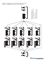
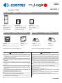
ML2262PLC
myLogic - Profilo
Posto esterno
PL72
Scatola da incasso
e telai portamoduli
Module frame complete with back-box
Posto interno
PROFILO
external door station
VD2120CPL
Modulo telecamera a colori
con gruppo fonico incorporato
Colour camera module with
integrated door speaker
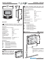
myLogic
ML2262C
Terminale domotico con schermo touchscreen
Touch-screen home automation terminal
CD2131PL
Modulo codificatore digitale con 1 pulsante
Digitizer module with 1 call
button
internal station
ML2083
Scatola da incasso
Back-box
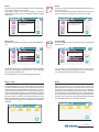
Il manuale d'uso inizia da pagina 35
IT AVVERTENZE DI SICUREZZA
Leggere attentamente le avvertenze contenute nel presente manuale
perché forniscono importanti informazioni riguardanti la sicurezza
di installazione, uso e manutenzione. Conservarlo in modo appropriato per future consultazioni.
Posizionare il terminale myLogic in ambiente asciutto e lontano da
fonti di calore o apparecchiature che producono calore e campi
magnetici.
Per la pulizia del terminale non usare acqua o solventi chimici, ma
un panno pulito. Per la pulizia dello schermo usare il panno allegato
al prodotto.
Questo apparecchio deve essere destinato solo all’uso per il quale
è stato concepito. Il costruttore non può essere considerato responsabile per eventuali danni derivati da usi impropri, erronei ed
irragionevoli.
Non lasciare alla portata dei bambini le parti dell’imballaggio (sacchetti di plastica, polistirolo espanso, ecc.).
Non aprire l’apparecchio quando è acceso.
L’esecuzione dell’impianto deve essere effettuato da personale
specializzato ed in conformità con le leggi vigenti.
In caso di guasto, funzionamento irregolare o modifica all’impianto
avvalersi di personale specializzato.
L’apparecchio è conforme alle direttive CEE (marchio europeo CE).
Alimentatori
2221S
Alimentatore di linea
Line power supply
Power supplies
2220S
Trasformatore
Transformer
The user’s manual begins on page 35
EN SAFETY NOTICES
Read the instructions contained in this manual carefully because
they provide important information about safe installation, use and
maintenance. Keep this manual appropriately for future reference.
Install your myLogic home automation terminal in a dry place away
from heat sources or devices that produce heat and magnetic fields.
Do not clean the home automation terminal with water or chemical
solvents, use a dry cloth for cleaning. To clean off the screen use
only the microfiber cloth which comes with the product.
This device must be exclusively operated for its intended use. The
manufacturer cannot be held responsible for possible damage
caused by improper, erroneous and unreasonable use.
Keep packing parts away from children (i.e. plastic bags, expanded
polystyrene, etc.).
Do not open the device when it is on.
The installation must be made by professionals in compliance with
the regulations in force.
Always refer to specialized personnel in case of breakdown,
irregular operation or change in the installation.
The device complies with the EEC directives (CE European mark).
Mi 2447IGb
Mi 2447IGb
-1-
POSTO INTERNO
INTERNAL STATION
EN Home automation hands free device with
colour touch-screen display for DUO digital system
Technical characteristics
Power supply directly from the line
Operating current:
Screen:
Television standard:
Horizontal frequency:
Vertical frequency:
Band width:
Thermostat:
Thermostat tollerance:
Thermostat resolution:
Automatic antifreeze:
Relay:
Maximum load contacts relay:
Operating temperature:
Maximum admissible humidity:
ML2262C.
0.2A
4.3" LCD touch-screen
PAL
15625Hz
50Hz
>5MHz
internal
+/- 1°C to 20°C
0.1°C
+3°C
2
12Vac / 12÷24Vdc - 1A
0° ÷ +50°C
90%RH
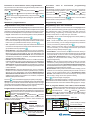
Terminal boards
LM / LM Line inputs
Floor call positive input
Floor call negative input
NO1
Normally open contact relay 1
NC1
Normally closed contact relay 1
C1
Common contact relay 1
NO2
Normally open contact relay 2
NC2
Normally closed contact relay 2
C2
Common contact relay 2
IT Terminale domotico vivavoce a colori con A1
GN
schermo touch-screen per sistema digitale DUO
Dati tecnici
Alimentazione direttamente dalla linea
Assorbimento:
0,2A
Schermo:
4,3" LCD touch-screen
Standard televisivo:
PAL
Frequenza di riga:
15625Hz
Frequenza di quadro:
50Hz
Banda passante:
>5MHz
Termostato:
interno
Tolleranza termostato:
+/- 1°C a 20°C
Risoluzione termostato:
0,1°C
Automatico antigelo:
+3°C
Relè:
2
Massimo carico contatti relè:
12Vca/12÷24Vcc - 1A
Temperatura di funzionamento: 0° ÷ +50°C
Massima umidità ammissibile: 90%RH
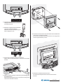
IT
Installazione
EN
Installation
Morsettiere
LM / LM
A1
GN
NO1
NC1
C1
NO2
NC2
C2
Ingressi di linea
Ingresso positivo chiamata di piano
Ingresso negativo chiamata di piano
Contatto normalmente aperto del relé 1
Contatto normalmente chiuso del relé 1
Comune del relè 1
Contatto normalmente aperto del relé 2
Contatto normalmente chiuso del relé 2
Comune del relé 2
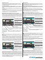
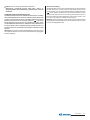
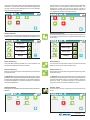
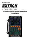
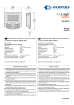
ML2083.
Scatola da incasso per
terminale domotico ML2262C.
EN Back-box for ML2262C
home automation terminal.
IT
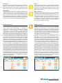
1 - Murare la scatola da incasso ML2083
ad un'altezza dalla pavimentazione di
circa 1,5 metri.
- Wall-up the back box ML2083 at an
height of about 1.5 meters above the
floor
Mi 2447IGb
-2-
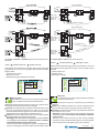
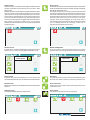
2 - Togliere le morsettiere dal terminale domotico.
- Unplug the terminal blocks from the home
automation terminal.
3 - Effettuare i collegamenti sulle morsettiere
come da schema da realizzare.
- Make the connections as required by the
electric diagram to wire.
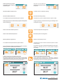
6 - Fissare il terminale domotico alla scatola da incasso utilizzando le
4 viti fornite a corredo del prodotto.
- Fix the home automation terminal to the back-box using the four
screws supplied with the product.
4 - Reinserire le morsettiere sul terminale domotico.
- Plug-in back the terminal blocks on the home automation
terminal.
5 - Sfilare la calotta frontale per accedere ai 4 punti di fissaggio del
terminale domotico.
- Remove the frontal plastic frame to reach the four fixing points
of the home automation terminal.
7 - Rimettere la calotta al terminale domotico.
- Re-insert the frontal plastic frame to the home automation
terminal.
Mi 2447IGb
-3-
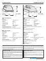
POSTO ESTERNO
VD2120CPL
EXTERNAL DOOR STATION
CD2131PL
Modulo telecamera con gruppo
fonico integrato
con un pulsante
Dati tecnici
Dati tecnici
Alimentazione:
13Vca±1
Assorbimento con collegamento al CD2131PL: 0,8A
Standard segnale video:
PAL
Illuminazione minima:
2,5 Lux
Led:
6 (bianchi)
Sensore:
CCD 1/3" a colori
Numero di pixel:
291.000
Ottica:
3,6mm
Messa a fuoco:
0,6m ÷ ∞
Brandeggio orizzontale/verticale:
±15°
Temperatura di funzionamento:
0°÷+40°C
Massima umidità ammissibile:
90% RH
Alimentazione dal modulo telecamera
VD2120CPL
Tempo azionamento serratura:
3/6 secondi
Numero di chiamate:
128
Indirizzo programmato di fabbrica: 231
Dimensioni:
1 modulo
Temperatura di funzionamento:
0°÷+40°C
Massima umidità ammissibile:
90% RH
IT
Morsetti
ingresso alimentazione alternata 13Vca
V ingresso segnale video di una telecamera esterna
supplementare (cavo coassiale)
M massa video (schermo coassiale)
EC comando positivo telecamera supplementare
EM comando negativo telecamera supplementare
IT Modulo codificatore digitale
Morsetti
LP/LP
EC
EM
S1/S2
fonia-dati-video da e verso gli interni
comando positivo per servizi ausiliari
comando negativo per servizi ausiliari
contatti apertura serratura
PL72
Scatola da incasso e
telai portamoduli.
IT
Module frame complete with back box
EN
/
Camera with integrated audio
module
EN
Technical data
Power supply:
13Vac±1
Absorption with connection to encoder CD2131PL:
0.8A
Video signal standard:
PAL
Minimum lighting:
2.5 Lux
LED's:
6 (white)
Sensor
CCD 1/3" colour
Number of pixel:
291,000
Lens:
3.6mm
Focusing:
0.6m ÷ ∞
Horizontal/vertical sweep:
±15°
Operating temperature:
0°÷+40°C
Maximum humidity acceptable:
90% RH
EN Digitizer module with 1 call
button
Technical features
Power supply from audio/video module
Door-opening time:
3 / 6 seconds
Number of calls:
128
Default address:
231
Dimensions:
1 module
Operating temperature:
0°÷+40°C
Maximum humidity acceptable: 90% RH
Terminals
LP/LP audio-data-video to and from internal
users
EC
positive signal for auxiliary services
EM
negative signal for auxiliary services
S1/S2 door opening contacts
Terminals
/
13VAC voltage input
V Video signal input of an additional external camera (coaxial cable)
M Video ground (coaxial shield)
EC Positive signal for supplementary camera
EM Negative signal for supplementary camera
Mi 2447IGb
-4-
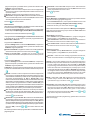
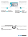
Installazione
Installation
1
2
VD2120CPL
CD2131PL
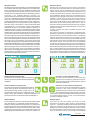
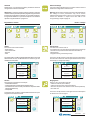
IT Muratura e passaggio dei cavi.
IT Posizione delle aperture passacavo.
EN Flush mounting and cables
placing.
EN Openings for cables.
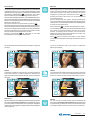
IT Posizionare la telecamera in modo che i raggi solari o
altre fonti luminose dirette o riflesse di forte intensità non
colpiscano l’obiettivo della telecamera.
Murare la scatola da incasso della pulsantiera ad un’altezza di
circa 1,65m dalla pavimentazione al lato superiore tenendo i bordi
frontali a filo e a piombo dell’intonaco finito.
EN Position the camera unit in such a way that
solar rays or other direct light or intense reflections do not hit the camera lens. Place the pushbutton panel back box at a height of about 1.65m (5'
5") from the floor keeping the front edges flushmounted and vertical to the finished plaster.
4
IT Agganciare la parte inferiore del telaio alla
scatola da incasso ed
effettuare i collegamenti
elettrici.
EN Fix lower part of
the frame to the back
box and make the
electrical connections.
3
7
IT Fissaggio del telaio alla
IT Fissaggio dei telai portamoduli
al riporto superiore tramite le 2 viti
piccole fornite a corredo delle scatole da incasso.
EN Fixing of the module frames
on the upper side by the 2 small
screws included in the back boxes.
5
scatola da incasso. Prima di
serrare le viti allineare il telaio.
EN Fixing of frame to back
box. Align the frame before
tightening the screws.
6
IT Collegare i moduli tramite il cavetto fornito a corredo
dell'art.CD2131PL.
EN Connect the modules
with the cable supplied with
art. CD2131PL.
IT Montaggio dei moduli al telaio.
EN Mounting modules.
Mi 2447IGb
-5-
ALIMENTATORI
POWER SUPPLIES
65
74
2 15/16"
2 9 /16"
54
1
2 /8"
IT
89
Art. 2220S
3 1 /2"
TRASFORMATORE
Dati tecnici
Tensione di rete:
127V o 220-230Vca
Frequenza:
50 ÷ 60 Hz
Potenza:
22VA
Tensione d’uscita:
13Vca ± 1
Corrente massima:
1A
Protezione in uscita:
PTC
Sicurezza:
conforme EN60065
Contenitore:
DIN 3 moduli A
Temperatura di funzionamento:
0° ÷+40°C
Massima umidità ammissibile:
90% RH
Fissabile su guida DIN o a muro con 2 tasselli ad espansione
EN
140
5 1/2 "
IT
Art. 2221S
89
3 1/2 "
ALIMENTATORE DI LINEA
Dati tecnici
Alimentazione di rete:
110V÷240Vca
Frequenza:
50 ÷ 60 Hz
Potenza:
60VA
Protezione in uscita:
PTC
Sicurezza:
conforme EN60065
Contenitore:
DIN 6 moduli A
Temperatura di funzionamento:
0° ÷+40°C
Massima umidità ammissibile:
90% RH
Fissabile su guida DIN o a muro con 2 tasselli ad espansione
Morsetti
PRI Ingresso alimentazione di rete
LP/LP Collegamento alla linea
TRANSFORMER
Technical data
Mains voltage:
127V or 220-230VAC
Frequency:
50 ÷ 60 Hz
Power:
22VA
Output voltage:
13Vac ± 1
Maximum current:
1A
Output protection:
PTC
Approved by:
according to the Safety Standard EN60065
Housing:
3 module A DIN
Operating temperature:
0° ÷+40°C
Maximum admissible humidity: 90% RH
Fits on DIN bar or with 2 expansion plugs
EN
LINE POWER SUPPLY
Technical data
Mains voltage:
110V÷240Vac
Frequency:
50 ÷ 60 Hz
Power:
60VA
Output protection:
PTC
Approved by:
according to the Safety Standard EN60065
Housing:
6 module A DIN
Operating temperature:
0° ÷+40°C
Maximum admissible humidity: 90% RH
Fits on DIN bar or with 2 expansion plugs
Terminals
PRI Mains voltage input
LP/LP Line output
Nota
Il trasformatore e l'alimentatore sono protetti contro sovraccarichi o
cortocircuiti da un sensore di temperatura (Termoprotettore). Per il
ripristino occorre togliere la tensione di rete per circa 1 minuto e ridare
tensione dopo aver eliminato il difetto.
Note
The transformer and the power supply are protected against overloads
or short-circuiting by a sensor (Thermoprotector), to restore power, it is
necessary to cut off the mains voltage for about one minute. Reconnect
power after having repaired the fault.
Avvertenze di sicurezza
- L'installazione del prodotto deve essere eseguita solo da PERSONALE QUALIFICATO in accordo con le regole di installazione vigenti.
- Il collegamento alla rete elettrica deve essere eseguito utilizzando
cavi di 1mm di diametro (AWG18).
- L’apparecchio non deve essere esposto a pioggia o spruzzi d’acqua.
- Un interruttore di rete bipolare, con una separazione dei contatti di
almeno 3mm in ciascun polo, deve essere incorporato nell’installazione elettrica del sistema.
Important safety instructions
- Installation shall be carried out from SKILLED PERSONS in accordance with all the applicable installation rules.
- Connection to the mains shall be done using 1mm diameter (AWG18)
conductors.
- The apparatus shall not be exposed to dripping or splashing.
- An all-pole mains switch, with a contact separation of at least 3mm in
each pole, shall be incorporated in the electrical installation of the
buildings.
Mi 2447IGb
-6-
Tabella delle distanze massime garantite
EN Table of the maximum allowed distances
IT
Tratta * Cavo Farfisa 2302 Cavo telefonico
Cavo CAT5
Section Farfisa 2302 cable Twisted cable
CAT5 cable
2x1mm² - AWG17 2x0,32mm² - AWG22 2x0,2mm² - AWG24
A
50 m - 164 ft
10 m - 33 ft
5 m - 17 ft
B
150 m - 328 ft
150 m - 328 ft
150 m - 328 ft
C
150 m - 328 ft
150 m - 328 ft
150 m - 328 ft
F
150 m - 328 ft
50 m - 164 ft
35 m - 115 ft
* Lettere di riferimento schematico (vedere gli schemi installativi a pagina 8).
Letters for reference on the diagrams (see page 8)
IT
Il segnale video può essere disturbato durante l'azionamento della serratura
elettrica. Per evitare questo inconveniente o per azionare serrature con
caratteristiche differenti da quella consigliata (12Vca 1A max.) si suggerisce
di utilizzare un alimentatore supplementare come riportato nello schema
seguente.
Inoltre, si consiglia di collegare, il più
vicino possibile ai terminali della serratura elettrica, un soppressore di disturbi (transil) per aumentare
l'affidabilità dell'impianto.
Collegamenti in uscita del terminale domotico
EN Output connection of home automation terminal
IT
Technical characteristics
Number of conductors: 2
Colour: red and black
Cross-section: 2x1mm² (AWG17)
Material: tinned copper
Twisting pitch: 40mm
Nominal impedance: 100Ω
Selezione impedenza di chiusura
Sul retro del terminale myLogic è posizionato il ponticello J12 che permette
di adattare il segnale video proveniente dalla montante e quindi consentire
un corretto funzionamento degli apparati ad esso collegati.
EN
carico / load 12Vca;
12÷24Vcc - 1A
Dati tecnici
Numero dei conduttori: 2
Colore: rosso e nero
Sezione: 2x1mm²
Materiale: rame stagnato
Passo di cordatura: 40mm
Impedenza caratteristica: 100Ω
Cavo Farfisa art.2302
EN Electrical door lock
The video signal may be disturbed during the operation of the electrical
lock. To avoid this problem or actuate locks with characteristics other
than recommended (12Vac 1A max.) an additional power supply
should be used as indicated in the diagram below.
It is also recommended to connect one interference suppressor
(transil) as close as possible to the terminals of
the electrical lock.
Serratura elettrica
IT
Cavo a 2 conduttori twistato consigliato per la realizzazione di impianti digitali DUO System. L'impiego di conduttori inadeguati potrebbe non garantire il corretto funzionamento del sistema.
EN Art.2302 Farfisa cable
Twisted pair cable specified for
the digital installation with DUO
systems. The use of inappropriate
cables may have an adverse effect on the performance of the system.
IT
Selecting the line impedance
The jumper J12 provided on the back of the home automation terminal can
be used to adjust the line impedance of video signal coming from the riser
and guarantee the correct operation of the devices connected to it.
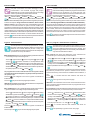
J12 Ponticello per adattare l'impedenza del segnale video
J12 Jumper to adjust the line impedance of the video signal
carico / load 12Vca;
12÷24Vcc - 1A
3-4
linea aperta
open line
IT
1
2
3
4
1
2
3
4
C2 NC2 NO2 C1 NC1 NO1 A1 GN J12 LM LM J13
- A riposo i contatti C e NO del relè sono aperti; chiusi quando attivato.
- A riposo i contatti C e NC del relè sono chiusi; aperti quando attivato.
EN
- Contacts C and NO of the relay are open in idle state and closed in
activation mode.
- Contacts C and NC of the relay are closed in idle state and open
in activation mode.
2-3
Ω
chiusura 15Ω
termination 15Ω
1
2
3
4
J12
1-2
Ω (di fabbrica)
chiusura 100Ω
Ω (default)
termination 100Ω
Mi 2447IGb
-7-
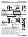
SCHEMI INSTALLATIVI
IT
INSTALLATION DIAGRAMS
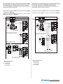
IMPIANTO VIDEOCITOFONICO MONOFAMILIARE
EN
ONE-WAY VIDEOINTERCOM SYSTEM
C
B
F
CD2131PL
PL72
LP
LP
EC
EM
S1
S2
art.2220S
LP LP
110V÷
240VAC
A
PRI
J1
PA
230V
127V
0
GN
A1
NO1
NC1
C1
NO2
NC2
C2
LM
LM
SE
J1 = togliere ponticello
remove jumper
VD2120CPL
Se occorre collegare all'impianto base uno
o più attuatori, sostituire il riquadro con uno
dei due presenti a pagina 9.
If it is required to connect to the basic
system one or more actuators, replace
the devices inside the dashed box with
one of the two indicated on page 9.
SE = Serratura elettrica (12Vca-1A max.)
FP= Pulsante chiamata di piano (opzionale)
PA = Pulsante apriporta (opzionale)
SE = Electric door lock (12VAC-1A max)
FP= Floor call push-button (optional)
PA = Door release push-button (optional)
IMPIANTO VIDEOCITOFONICO MONOFAMILIARE
CON 2 TERMINALI DOMOTICI
IT
Relè 1
Relay 1
Relè 2
Relay 2
ML2262
ML2083
1
2
3
4
art.2221S
FP
J12 = 1-2
J12 =lasciare su 1-2
leave on 1-2
ONE-WAY VIDEOINTERCOM SYSTEM WITH 2 HOME
AUTOMATION TERMINALS
EN
C
J1 = togliere ponticello
remove jumper
B
CD2131PL
PL72
LP
LP
LM
LM
EC
EM
S1
S2
art.2220S
LP LP
110V÷
240VAC
A
PA
230V
127V
0
PRI
J1
art.2221S
SE
J1 = togliere ponticello
remove jumper
VD2120CPL
SE = Serratura elettrica (12Vca-1A max.)
FP= Pulsante chiamata di piano (opzionale)
PA = Pulsante apriporta (opzionale)
SE = Electric door lock (12VAC-1A max)
FP= Floor call push-button (optional)
PA = Door release push-button (optional)
F
Se occorre collegare all'impianto base uno
o più attuatori, sostituire il riquadro con uno
dei due presenti a pagina 9.
If it is required to connect to the basic
system one or more actuators, replace
the devices inside the dashed box with
one of the two indicated on page 9.
1
2
3
4
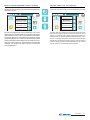
EN To make a one-way installation with 2 home automation terminals you must:
- add an additional ML2262C terminal and another ML2083 back box to the videokit;
- move the jumper J12 of the terminal VC1 from position 1-2 to 3-4; leave it on 1-2 in the VC2;
- change the room number of one of the two home automation terminal from “0” to “1” (as indicated in
section "How to programme Address, User Name, Room Number" on page 20). The main home
automation terminal is the one with code “0” and will automatically switch ON upon an external call. The
home automation terminal with code “1” can see and talk with the external door station by pressing the
button.
FP
Relè 1
Relay 1
Relè 2
Relay 2
ML2262
ML2083
J12 = 3-4
LM
LM
IT Per realizzare un impianto monofamiliare con 2 terminali domotici, occorre:
- aggiungere al videokit un ulteriore terminale ML2262C ed un'altra scatola da incasso ML2083;
- spostare il ponticello J12 del terminale VC1 dalla posizione 1-2 alla 3-4; lasciarlo su 1-2 nel VC2;
- cambiare il numero di stanza di uno dei due terminali da "0" a "1" (procedere come indicato nel
paragrafo "Programmazione Indirizzo, Nome utente, Numero stanza" di pagina 20). Si ricorda che il
terminale principale è quello con il codice "0" e si accenderà automaticamente alla chiamata da esterno;
mentre il terminale con il codice "1" può visionare e comunicare con l'esterno premendo
.
GN
A1
NO1
NC1
C1
NO2
NC2
C2
1
2
3
4
GN
A1
NO1
NC1
C1
NO2
NC2
C2
FP
Relè 1
Relay 1
Relè 2
Relay 2
ML2262
ML2083
J12 = 1-2
J12 = posizionare il ponticello di ogni terminale domotico come indicato nello schema.
set the jumper of each home
automation terminal as indicated in
the diagram.
Mi 2447IGb
-8-
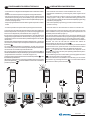
Esempi applicativi per collegare più attuatori 2281
(massimo 9) per l'attivazione di ulteriori servizi
Examples of connecting more actuators 2281 (max
9) for the activation of additional functions
(lo schema del riquadro scelto sostituisce quello presente nel riquadro
degli schemi installativi di pagina 8)
(the diagram inside the dashed box take the place of that present in
the installing diagram reported on page 8)
Alimentazione attuatori 2281 tramite un alimentatore 2221S
e distributore DV2420
Powering actuators 2281 by means of a power supply
2221S and distributor DV2420
Alimentazione attuatori 2281 tramite un trasformatore PRS210
LP
LP
LP
LP
LI
LI
LM
LM
LO
LO
LM LM
LM
LM
LP LP
110V÷
240VAC
PRI
Art.2221S presente nel videokit
Art.2221S present in videokit
Fino a 2 attuatori art.2281
Up to 2 actuators art.2281
art.2221S
2281
LM
LM
LP LP
LM
LM
2281
J1=2-3
LM
LM
LD
LD
LO
LO
J1
J1
J1 = ponticello inserito
jumper inserted
aggiungere al videokit:
add to videokit:
2 = art.DV2420
1 = art.2221S
1÷9 = art.2281
2281
J1=1-2
“2”
Art.2221S presente nel videokit
Art.2221S present in videokit
LM
LM
PRS210
230V
127V
0
IN
COM
OUT
NC
NA
C
2281
J1=1-2
“3”
LM
LM
110V÷240VAC
Massimo altri 6 art.2281
Max. 6 extra art.2281
IN
COM
OUT
NC
NA
C
PRI
“2”
IN
COM
OUT
NC
NA
C
“1”
DV2420
art.2221S
110V÷
240VAC
J1=2-3
LM
LM
LO
LO
LM LM
DV2420
LP
LP
PRI
IN
COM
OUT
NC
NA
C
J1
J1 = ponticello inserito
jumper inserted
LI
LI
“1”
DV2420
art.2221S
Powering actuators 2281 by means of a transformer PRS210
J1=2-3
IN
COM
OUT
NC
NA
C
Massimo altri 7 art.2281
Max. 7 extra art.2281
2281
aggiungere al videokit:
add to videokit:
1 = art.DV2420
1 = art.PRS210
1÷9 = art.2281
Mi 2447IGb
-9-
IT FUNZIONAMENTO VIDEOCITOFONICO
EN VIDEOINTERCOM OPERATION
- Controllare che i collegamenti dell'impianto siano effettuati correttamente.
- Mettere in funzione l'impianto collegando a rete gli alimentatori.
- Alla prima accensione o dopo un lungo periodo di tempo senza
alimentazione (circa 2 giorni), il terminale myLogic, dopo una breve
fase di caricamento dati, avvia la procedura semplificata di programmazione (vedi pagina 20).
- Dopo la programmazione il terminale è in grado di operare correttamente.
- Check that the connections of the installation are correct.
- Operate the installation by connecting the power supplies to the
mains.
- Upon first switch-ON or after a long period of time without power
supply (approx. 2 days), after a short data loading operation, the
myLogic home automation terminal starts the simplified programming
procedure (see page 20).
- After the simplified programming procedure the terminal can
operate correctly.
- Premere il pulsante sul posto esterno per eseguire la chiamata.
- Press the button on the external door station to make the call.
L'avvenuto invio è confermato sul posto esterno da un tono di libero se
la linea è disponibile o di occupato (con Led rosso lampeggiante) se
la linea non è disponibile (vedi tabella dei toni a pagina 17).
Il posto interno squillerà con temporizzazioni e melodie definite da
un'apposita programmazione del terminale (vedi pagina 60); se in
questa fase si preme ancora lo stesso pulsante l'apparecchio squilla
nuovamente.
Sul terminale chiamato appare l'immagine dell'ingresso. L'utente può
conversare con l'esterno per un tempo di circa 90 secondi premendo
.
il pulsante
A 10 secondi dalla fine della conversazione, si udrà un tono di fine
conversazione; premere nuovamente il pulsante del posto esterno per
continuare la conversazione per altri 90 secondi.
Per azionare l'apertura della serratura premere il pulsante
. La
durata dell'abilitazione dipende dalla programmazione scelta (vedi
"programmazione di sistema - modo 2B" di pagina 13).
L'impianto ritorna a riposo premendo nuovamente il pulsante
o alla
fine della temporizzazione.
Ad impianto videocitofonico a riposo è possibile visionare l'ingresso
; qualora si desideri comunicare con l'esterno
premendo il pulsante
premere il pulsante
.
Call is confirmed on the external door station with a free tone if the
line is available or a busy tone (with flashing red Led) if the line is not
available (see tone table to page 17).
The internal station rings with the time and ringer defined by the
specific home automation terminal programming operation (see page
60); the device will ring again if you press the same button again.
The image of the entrance appears on the called home automation
terminal. The user can talk with the external door station for
approximately 90 seconds by pressing
.
10 seconds before the end of the conversation you will hear the end
of conversation tone; press the button on the external door station
again to continue the conversation for additional 90 seconds.
Press
to open the lock. The activation time depends on the
programming you have chosen (see “operating mode of the system code 2B” on page 13).
The installation goes back to idle state by pressing again the button
or at the end of the conversation time.
When the videointercom installation is in idle state you can monitor
; to communicate with the
the entrance by pressing the button
external door station press the button
.
Mi 2447IGb
- 10 -
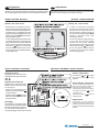
IT Regolazioni
I livelli fonici sono regolati in fabbrica; modificare le regolazioni poste
sul retro dell'apparecchio solamente in caso di effettiva necessità.
EN Adjustments
The audio levels are set in the factory; settings on the back of the
device must be changed only if really necessary.
VIDEOCITOFONO ML2062C
ML2062C VIDEOINTERCOM
Taratura dei livelli fonici.
Setting the sound levels.
- Se durante la conversazione si ode un
audio eccessivamente intermittente o se
durante una chiamata l'altoparlante tende a distorcere, si consiglia di ritoccare
leggermente la sensibilità del microfono
agendo sul trimmer SENS posto sul retro
del terminale domotico.
- In caso di difficoltà a prendere la linea in
una delle due direzioni, aumentare leggermente il livello del canale in difficoltà
e diminuire leggermente l’altro agendo
sul trimmer
VOL per il volume del
microfono e sullo schermo touch-screen
di myLogic per il volume dell'altoparlante
(vedi a pagina 40).
- If audio is excessively intermittent
during the conversation or the speaker
tends to distort it during the call, it is
recommended to slightly change the
microphone sensitivity using the SENS
trimmer on the back of the home
automation terminal.
- In case of problems in getting the line
in one of the two directions, slightly
increase the level of the disturbed
channel and decrease the level of the
other channel using the VOL trimmer
for the microphone volume and the
myLogic touch-screen for the speaker
volume (see page 40).
POSTO ESTERNO VD2120CPL
VD2120CPL EXTERNAL DOOR STATION
Regolazione volumi
Per regolare i volumi del microfono
e dell'altoparlante, agire sui trimmer
e .
Volume adjustment
Regolazione dell’antilocale
Per eliminare un eventuale innesco
(effetto Larsen), occorre procedere come segue:
- eseguire la chiamata dal posto
esterno e premere il pulsante
sul videocitofono;
sul posto
- regolare il trimmer
esterno fino ad ottenere l’annullamento del fischio.
Anti-feedback adjustment
Brandeggio
Se necessario, è possibile variare
manualmente l'inquadratura della
telecamera allentando e spostando, nella direzione desiderata, la
vite del brandeggio orizzontale e verticale.
Use trimmers
and to adjust
the volume of microphone and
speaker.
±15°
In case of "feedback" (Larsen effect) in the external door station it is
necessary to operate as follow:
-make the call from the door station
and press the button
on the
videointercom;
-adjust the trimmer
until the
whistling stops.
Adjustments
If necessary, you can manually
change the camera framing by unloosening the fixing screw and adjusting horizontally and vertically the
camera.
Mi 2447IGb
- 11 -
CD2131PL
IT Programmazione
EN Programming
Il modulo codificatore CD2131PL, presente nel videokit, è programmato
con lo stesso codice di chiamata del posto interno (100), pertanto non
necessita di nessuna programmazione. Solo nei casi in cui si voglia
variare alcune funzioni od aggiungere ulteriori apparati al videokit si deve
procedere alla programmazione del codificatore eseguendo le seguenti
fasi:
The CD2131PL digitizer module included in the videokit is programmed
with the same calling code as the internal station (100) and therefore
needs no programming. The encoder module must be programmed as
illustrated below only if you want to change some functions or add
additional devices to the videokit:
1)
2)
3)
4)
1) enter programming mode
2) insert code of desired programming
3) insert required address or functional code
4) exit programming mode
entrare in modalità programmazione
inserire il codice della programmazione che s'intende effettuare
inserire l'indirizzo richiesto o il codice della funzione desiderata
uscire dalla programmazione
Note
- In qualunque momento è possibile uscire dalla fase di programmazione
seguendo le indicazioni del paragrafo 4.
- Per eseguire altre programmazioni è sufficiente ripetere più volte le fasi
2 e 3.
Notes
- In any situation it would be possible to exit the programming phase
following the instructions reported on paragraph 4.
- To proceed with other programming repeat the phases 2 and 3.
1) Entrata in modalità programmazione
1) Enter programming mode
Move the jumper J1 from 2-3 to 1-2 position; a programming tone will
confirm the correct operation.
Spostare il ponticello J1, posto sul retro della pulsantiera, dalla posizione 2-3 alla 1-2; si udirà il tono di programmazione.
Posizioni ponticello J1
Position of jumper J1
2-3 = modalità funzionamento
2-3 = operating mode
1-2 = modalità programmazione
2) Inserimento modi di selezione della programmazione
Sui microinterruttori MS1 e
MS2, impostare il codice della programmazione che s'intende eseguire come riportato nella tabella 1 di pagina 13
(modi 1A, 2A, 1B, 2B e AA).
Premere il tasto di conferma
SW.
3) Programmazione indirizzo o codice funzione
1-2 = programming mode
2) Insert code of desired programming
On the micro-switches MS1
and MS2 set the code corresponding to the programming
operation you wish to enter
as reported on table 1 of page
13 (codes 1A, 2A, 1B, 2B
and AA).
Press the programming button SW.
Sui microinterruttori MS1 e MS2, impostare l'indirizzo desiderato usando la corrispondenza riportata nella tabella 3 delle pagine 15, 16 e 17.
Per le programmazioni di sistema (codice 2B) vedere la tabella 2 di
pagina 13.
Premere il tasto di conferma SW.
3) Insert required address or functional code
On the microswitches MS1 and MS2 set the address you wish to enter
in accordance with the cross-references reported on table 3 of pages
15, 16 and 17.
For the codes to enter see table 2 of page 13 (code 2B).
Press the programming button SW.
- Ripetere più volte le fasi 2 e 3 fino alla completa programmazione del
codificatore.
- Ad ogni pressione del tasto SW un tono di conferma o di errore indicherà
l'immissione di un codice corretto o sbagliato; nel secondo caso sarà
necessario reinserire il codice esatto.
- Repeat phases 2 and 3 until you have completely programmed the
Digital Encoder.
- Any time you press the SW button an acknowledge or error tone will
warning you whether the entered code is correct or not; in case of
incorrect code you must enter again the correct one.
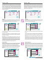
4) Uscita dalla modalità programmazione
4) Exit programming mode
To exit the programming phase it is necessary to set OFF all the
microswitches MS1 and MS2 and move back the jumper J1 from 1-2 to
2-3 position.
Per uscire dalla programmazione è necessario posizionare tutti i
microinterruttori di MS1 e MS2 su OFF e riportare il ponticello J1 dalla
posizione 1-2 alla 2-3.
MS1
ON
1 2 3 4
MS2
ON
1 2 3 4
posizione dei microinterruttori MS1, MS2 e del ponticello
J1 per uscire dalla fase di programmazione
MS1
ON
1 2 3 4
MS2
ON
1 2 3 4
position of MS1, MS2 microswitches and jumper J1
to exit the programming phase.
Mi 2447IGb
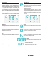
- 12 -
Tabella 1
Codici di selezione dei modi di programmazione
Modo
MS1
MS2
1
A
MS1
MS2
1
B
MS1
MS2
1A
Modo
1B
Modo
2B
Modo
2
B
MS1
MS2
1E
Modo
1
E
MS1
MS2
AA
A
Table 1
Selection type of the programming
Indirizzo o funzione da programmare
Address or function to be programmed
Indirizzo associato al primo pulsante di chiamata. Codici
da 1 a 200 (vedere tabella 3 alle pagine 15, 16 e 17).
Di fabbrica 100.
User address associated to the first button.
Codes from 1 to 200 (see table 3 of the pages 15,
16 and 17). Default 100.
Indirizzo del posto esterno. Codici da 231 a 250 (vedere
tabella 3 a pagina 17).
Di fabbrica 231.
Address of the external door station. Codes from
231 to 250 (see table 3 of the page 17).
Default 231.
Programmazioni di sistema (vedere tabella 2).
System programming (see table 2).
Indirizzo associato ai morsetti EC-EM
Address associated with terminals EC-EM
Ritorno alla programmazione di fabbrica.
Codice 170 (vedere tabella 3 a pagina 16).
Set the device back to factory settings.
Code 170 (see table 3 of page 16).
A
Tabella 2
Programmazioni di sistema (modo 2B)
Table 2
Operating mode of the system (code 2B)
Posizione microinterruttori di MS1 - MS2
Microinterruttori
Micro-switches
OFF
ON
OFF
1
tempo di azionamento della serratura; 3 secondi **
tempo di azionamento della
serratura; 6 sec.
door lock activation time;
3 seconds **
door lock activation
time; 6 seconds
2
chiamata da interno NON
abilitata ***
chiamata da interno abilitata
**
deactivation upon call
from internal station ***
activation upon call
from internal station **
3
riservato: lasciare in posizione OFF **
4
generatore di toni sul posto
esterno; abilitato **
MS1
ON
Micro-switches position of MS1 and MS2
ON
1 2 3 4
1-2
reserved: to leave in position OFF **
generatore di toni sul posto
esterno; NON abilitato.
riservato: lasciare in posizione OFF **
ACTIVATION of tone
generator on the external door station **
DEACTIVATION of
tone generator on the
external door station
reserved: to leave in position OFF **
MS2
ON
3
normale gestione morset-ti
EC-EM
gestione morsetti EC-EM per
telecamera supplementare
ordinary management of
terminals EC-EM
management of
terminals EC-EM for
additional camera
tempo di azionamento della serratura supplementare; 3 secondi **
tempo di azionamento della
serratura supplementare;
6 secondi
supplementary door lock
activation time;
3 seconds **
supplementary door
lock activation time;
6 seconds
1 2 3 4
4
** Programmazione di fabbrica.
*** Abilitando questa funzione da ogni interno è possibile, premendo il
pulsante , entrare in conversazione con un posto esterno (nel caso
di più posti esterni in parallelo si entra in comunicazione con l'ultimo
posto esterno che ha effettuato la chiamata) ed azionare la serratura
premendo il pulsante
.
** Factory setting.
button, start
*** This function allows the internal stations to press the
a conversation with the external station (in case of more external
stations in parallel the connection is established with the last calling
door station) and activate the door lock by pressing the button
.
Mi 2447IGb
- 13 -
12
J1
23
J1
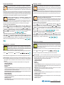
PROGRAMMAZIONE
ENTERING THE
PROGRAMMING MODE
ENTRATA IN
1-2
2-3
MS2
MS1
+
SW
MS2
MS1
+
SW
MS2
MS1
+
SW
MS2
MS1
+
SW
MS2
MS1
+
SW
SCELTA MODO DI PROGRAMMAZIONE
SELECTING THE PROGRAMMING TYPE
1 2 3 4
ON
A
1 2 3 4
ON
Modo A
SCELTA MODO DI PROGRAMMAZIONE
SELECTING THE PROGRAMMING TYPE
1 2 3 4
ON
E
1 2 3 4
ON
Modo 1
SCELTA MODO DI PROGRAMMAZIONE
SELECTING THE PROGRAMMING TYPE
1 2 3 4
ON
B
1 2 3 4
ON
Modo 2
SCELTA MODO DI PROGRAMMAZIONE
SELECTING THE PROGRAMMING TYPE
1 2 3 4
ON
B
1 2 3 4
ON
Modo 1
SCELTA MODO DI PROGRAMMAZIONE
SELECTING THE PROGRAMMING TYPE
1 2 3 4
ON
A
1 2 3 4
ON
Modo 1
MS2
1 2 3 4
ON
+
SW
MS2
1 2 3 4
ON
+
SW
MS2
1 2 3 4
ON
(*)
MS2
1 2 3 4
ON
+
+
SW
SW
MS2
1 2 3 4
ON
+
RITORNO ALLA PROGRAMMAZIONE DI FABBRICA (CODICE 170)
SET THE DEVICE BACK TO FACTORY SETTINGS (CODE 170)
MS1
1 2 3 4
ON
SW
MODALITA’ TELECAMERA SUPPLEMENTARE (CODICE 255)
SUPPLEMENTARY CAMERA MODE (CODE 255)
MS1
1 2 3 4
ON
MS1
1 2 3 4
ON
INDIRIZZO POSTO ESTERNO (ESEMPIO 233)
DOOR STATION ADDRESS (EXAMPLE 233)
MS1
1 2 3 4
ON
INDIRIZZO PRIMO PULSANTE (ESEMPIO 10)
FIRST PUSH-BUTTON ADDRESS (EXAMPLE 10)
MS1
1 2 3 4
ON
J1
12
SYSTEM PROGRAMMING (EXAMPLE:
- DOOR LOCK TIME 3 SECONDS;
- EXTERNAL DOOR STATION IS ENABLED BY USER;
- TONE ON EXTERNAL DOOR STATION IS DISABLED)
- EC-EM TERMINALS FOR SUPPLEMENTARY CAMERA
- TEMPO DI ABILITAZIONE SERRATURA 3 SECONDI;
- ABILITAZIONE DEL POSTO ESTERNO DALL’UTENTE;
- TONO SUL POSTO ESTERNO DISABILITATO;
- MORSETTI EC-EM PER TELECAMERA SUPPLEMENTARE)
(*) PROGRAMMAZIONE DI SISTEMA (ESEMPIO:
EXIT THE PROGRAMMING MODE
MS2
MS1
+
USCITA DALLA PROGRAMMAZIONE
1 2 3 4
ON
1 2 3 4
ON
1-2
J1
23
2-3
Esempio di programmazione del codificatore digitale CD2131PL
Example of programming for digital encoder CD2131PL
Mi 2447IGb
- 14 -
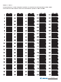
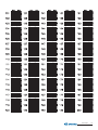
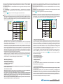
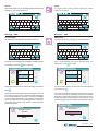
Tabella 3 - Table 3
Corrispondenza tra i codici assegnati ai pulsanti e la posizione dei microinterruttori di MS1 e MS2.
Cross-reference table between codes and microswitches position of MS1 and MS2.
Mi 2447IGb
- 15 -
Mi 2447IGb
- 16 -
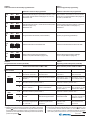
Tabella dei toni
Fine conversazione / programmazione errata.
Indica un errore durante la programmazione o che, dopo 10
secondi, termina la conversazione.
Occupato.
Indica che l'interno o la linea sono occupati o l'interno non esiste.
Tone table
End of conversation / wrong programming.
Indicates an error during the programming phase or that the
conversation time is near to expire.
Busy.
Indicates that the user is busy or not existing or that the line is busy.
Dissuasione.
Indica una errata programmazione del pulsante premuto.
Dissuasion.
Indicates that the push-buttons were wrongly programmed.
Programmazione.
Indica che si è in modalità programmazione.
Programming .
Indicates that the programming mode was accessed.
Conferma. Indica la corretta operazione eseguita
(programmazione, invio chiamata, apriporta in conversazione,
prolungamento tempo di conversazione)
Acknowledge. It indicates that the operation was performed
correctly (programming, call send, door lock in conversation,
extension of conversation time)
Mi 2447IGb
- 17 -
IT PROGRAMMAZIONI
Il terminale domotico myLogic deve essere programmato
opportunamente per definirne il modo di funzionamento. La maggior
parte delle programmazioni sono semplici e necessitano di essere
modificate al variare delle esigenze domestiche, sono quindi descritte
nel manuale d’uso e possono essere eseguite dall’utente. Altre invece
sono più complesse, in quanto devono rispecchiare l’impiantistica del
sistema, ed una loro errata impostazione può provocare
malfunzionamenti gravi del prodotto; esse sono descritte nel presente
manuale e devono essere eseguite dall’installatore o da personale
esperto.
Al termine delle programmazioni è vivamente consigliato proteggerle
seguendo la procedura indicata nel capitolo "Procedura blocco/
sblocco delle programmazioni" (pagina 20).
Programmazioni eseguibili
indirizzo utente (obbligatorio); indirizzo di identificazione
dell’appartamento (indirizzi da 1 a 200). Permette di ricevere la
chiamata da esterno o da altro apparecchio presente nello stesso
palazzo, accendere il videocitofono, conversare ed aprire la serratura
del posto esterno chiamante. L’indirizzo dovrà essere lo stesso
memorizzato nel tasto di chiamata della pulsantiera del posto esterno
o nel tasto di chiamata di un altro apparecchio intercomunicante di
palazzo.
numero stanza (obbligatorio se vi sono più apparecchi nello stesso
appartamento); indirizzo di identificazione dell’apparecchio all’interno
dello stesso appartamento (indirizzi da 0 a 7). Il numero di stanza
stabilisce anche una gerarchia negli apparati interni in quanto
l’apparecchio che avrà l’indirizzo di stanza 0 (zero) sarà definito
principale, gli altri saranno tutti secondari. Eseguita questa
programmazione sarà possibile effettuare e ricevere chiamate
selettive con gli altri apparecchi all’interno dello stesso appartamento
cioè ogni apparecchio potrà chiamare singolarmente gli altri. Le
chiamate da esterno o da altro appartamento faranno invece squillare
tutti i dispositivi, il primo che risponderà attiverà la conversazione e
spegnerà le sonerie degli altri. All’arrivo di una chiamata da posto
esterno dotato di telecamera tutti gli apparecchi squillano, ma solo
il principale (indirizzo di stanza 0 -zero) mostra l’immagine della
telecamera. In questa fase è possibile, anche da un terminale
secondario, visualizzare l’immagine della telecamera senza rispondere
premendo il tasto telecamera “
”. E’ possibile rispondere alla
chiamata anche dai terminali secondari premendo il tasto videocitofonia
; tale operazione spegne le sonerie di tutti i dispositivi e mostra
l’immagine della telecamera sul display del terminale utilizzato
rimuovendola da quello del terminale principale. La chiamata di piano
fa squillare solo il terminale a cui il pulsante di chiamata è fisicamente
connesso. Volendo rilanciare tale chiamata anche agli altri terminali
seguire le istruzioni del paragrafo "rilancio campanello" a pag.33.
Creazione/eliminazione di nuovi attuatori ed eventi (obbligatorio
se ci sono attuatori o eventi nell’impianto); si possono creare nuovi
attuatori o eventi definendo il loro nome ed il loro indirizzo oppure
cancellarli.
Nome attuatore o evento, mnemonico con il quale è individuato un
attuatore o un evento all’interno del sistema, normalmente il nome
rispecchia la funzione che il dispositivo esegue (es: l’attuatore che
accende l’impianto di irrigazione si chiamerà “IRRIGAZIONE” o il
sensore che rivela la pioggia si chiamerà “PIOGGIA”).
Indirizzi degli attuatori e degli eventi art.2281 (obbligatorio se ci
sono attuatori o eventi nell’impianto); indirizzo che identifica ogni
singolo attuatore (indirizzi da 211 a 220) o evento (indirizzi da 221
a 230). L’indirizzo dell’attuatore o dell’evento permette di scambiare
selettivamente dati e comandi tra gli attuatori o gli eventi ed il terminale
myLogic, consente a quest’ultimo di gestire correttamente la parte
domotica dell’impianto.
Creazione/eliminazione di nuovi ingressi videocitofonici
(obbligatorio se ci sono più ingressi videocitofonici nell’impianto);
EN PROGRAMMING
The myLogic home automation terminal must be suitably programmed
to define the operation mode. Most programming operations are
simple and need to be changed in case of new domestic requirements.
For this reason, they are described in the user manual and can be
carried out by the user. Instead, other operations are more complicated
because they must respect the installation of the system. Incorrect
settings can cause severe malfunctioning. They are described in this
manual and must be carried out by the installer or expert users.
At the end of the programming operations it is strongly recommended
to protect them by following the procedure illustrated in section
“Procedure used to lock/unlock programming operations” (page 20).
Executable programming operations
user address (mandatory); apartment identification address
(addresses from 1 to 200). It allows to receive an external call or a
call from another device installed in the same building, switch-ON
the videointercom, have a conversation and open the door lock of
the calling external door station. The address must be the same
address saved in the call button of the push-button panel of the
external door station or in the call button of another intercom device
of the building.
room number (mandatory in case of multiple devices in the same
apartment); device identification address inside the same apartment
(addresses from 0 to 7). The room number establishes a hierarchy
in the internal devices since the device with room address 0 (zero)
will be the main device and all the other devices will be the secondary
devices. Once you have made this programming operation, you will
be able to make and receive selective calls with the other devices
inside the same apartment. In other words, each device can
individually call the other devices. The external calls or calls from
another apartment will make all devices ring, the first device that
answers the call will activate the conversation and switch OFF the
ringer of the other devices. When you receive a call from an external
door station equipped with camera, all the devices will ring, but only
the main device (room address 0 - zero) will display the camera
image. In this phase you can display the camera image also from
a secondary home automation terminal without answering by
pressing the camera button “
”. You can answer the call also from
the secondary home automation devices by pressing the
. This operation will switch OFF the ringer
videointercom button
of all the terminals and will display the camera image on the display
of the used home automation terminal. In case of floor call only the
home automation device to which the call button is physically
connected will ring. To drive the call to the other home automation
terminals you must follow the instructions contained in the section
“Floor call extension” on page 33.
Create/delete new actuators or events (mandatory if at least one
actuator or event is present in the installation).
Name of an actuator or an event, reminder with which an actuator
or an event is called in an installation, normally the name reminds
the function which the device performs (e.g.: the actuator which
controls the watering system of a garden will be named “GARDEN
WATERING” or the sensor which detects the rain will be named
“RAIN CONTROL”.
Addresses of actuators or events art 2281 (mandatory if at least
one actuator or event is present in the installation); the address
identify each single actuator (addresses from 211 to 220) or event
(addresses from 221 to 230). The addresses of actuators and events
allow exchanging selectively data and commands among them and
the myLogic terminal, besides allows the last one to manage
correctly the home automation functions of the system.
Creation/deletion of new videointercom entrances (mandatory in
case of multiple videointercom entrances in the installation); you can
Mi 2447IGb
- 18 -
si possono creare nuovi ingressi definendo il loro nome ed il loro
indirizzo oppure cancellarli.
Nome ingresso videocitofonico, mnemonico con il quale è
individuato un ingresso videocitofonico all’interno del sistema (es.
“INGRESSO VIA VERDI” o “INGRESSO PRINCIPALE”).
Indirizzi dei posti esterni per accensioni di controllo (obbligatorio
se vi sono più posti esterni); indirizzo che identifica univocamente
ciascun posto esterno presente nell’impianto (indirizzi da 231 a 250).
L’indirizzo dei posti esterni permette al terminale domotico di collegarsi
singolarmente con essi, eseguire accensioni di controllo ed
eventualmente aprire la serratura.
Termoregolazione impostazione relé interno od esterno
(obbligatorio se il terminale myLogic comanda l’impianto di
riscaldamento o condizionamento dell’appartamento); si può
decidere se l’impianto di termoregolazione dell’appartamento è
gestito dal relé interno al terminale myLogic o da un relé esterno
tramite un attuatore.
Attenzione: gli indirizzi dei dispositivi memorizzati nel terminale
domotico devono coincidere con quelli programmati negli ingressi
videocitofonici e negli attuatori/eventi (vedere le istruzioni presenti nei
prodotti).
create new entrances, defining their name and addresses, or you
can delete them.
Videointercom entrance name, mnemonic name used to identify
the videointercom entrance in the system (i.e.”EDISON STREET
ENTRANCE” or “MAIN ENTRANCE”).
Addresses of external door stations for control switch-ON
(mandatory in case of multiple external door stations); address used
to univocally identify each station of the system (addresses from
231 to 250). The address of the external door stations allows the
home automation terminal to connect with them individually, use the
control monitor function and open the door lock.
Thermal control setting internal or external relay (mandatory if
myLogic terminal controls heating or conditioning system of the
apartment).
Warning: the addresses of the devices saved in the home automation
terminal must coincide with the addresses programmed in the
videointercom entrances and in the actuators or events (see instructions
in the technical manual of the devices).
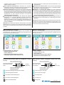
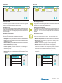
Menu o pannello di controllo
Menu or control panel
Premendo sulle icone di questa pagina si può accedere alle
programmazioni, impostazioni ed inserimento informazioni per il
funzionamento del terminale domotico.
Press the icons on this page to access the programming operations,
settings, and information entering functions to operate the home
automation terminal.
02.07.10
Videocitofonia
11:18
30,3°
Interfono/SMS
02.07.10
Blocco note
Videointercom
°C
Intercom/SMS
Notes
°C
Termoregolazione
Attuazioni/Eventi
Sicurezza
Heating control
Actuators/Events
Security
Preferiti
Immagini
Impostazioni
Favourites
Backgrounds
Settings
Programmazione di fabbrica
-
11:18
30,3°
Default settings
indirizzo appartamento = 100
numero stanza = 0
nome ingresso videocitofonico = ingresso
indirizzo dell’ingresso videocitofonico = 231
-
Principali tasti funzione (tasto di navigazione e touchscreen)
menu o pannello di controllo
accensione telecamere,
inizio e fine conversazione
pagina precedente
apartment address = 100
room number = 0
videointercom entrance name = ingresso
videointercom entrance address = 231
Main function buttons (navigation button and touchscreen)
menu or control panel
serratura
(apriporta)
camera switch-ON,
start and end of
conversation
lock
(door open)
previous page
conferma e passaggio alla pagina successiva
confirm and go to next page
ritorno alla pagina precedente
go back to previous page
scorrimento in basso della pagina
scroll page down
scorrimento in alto della pagina
scroll page up
gestione modifica dei dati
change data
Mi 2447IGb
- 19 -
Procedura di blocco/sblocco delle programmazioni
Per poter bloccare o sbloccare le programmazioni protette occorre
eseguire la procedura seguente:
"menu" "impostazioni" "avanzate" (videocitofonia
serratura
)
"varie"
selezionare "protezione attiva"
"modifica"
NO per sbloccare le programmazioni (o SI per bloccarle)
Procedure
operations
used
to
lock/unlock
programming
The following procedure must be carried out to lock or unlock the
protected programming operations: “menu” “settings” “advanced”
(videointercom
lock release
“protection activated”
“modify”
)
“others”
select
NO to unblock programming
"menu". Per maggiori dettagli vedere il paragrafo "protezione attiva"
a pagina 32.
operations (or YES to block them)
“menu”. For more details
see the section “active protection” on page 32.
Modalità di programmazione
Programming modes
Programmazione alla prima accensione
Programming upon first switch-ON
Alla prima accensione il terminale myLogic, dopo una fase di caricamento
dati (circa 15 secondi), avvia una procedura semplificata che guida
l’installatore nella programmazione dei dati necessari per il corretto
funzionamento del dispositivo. In sequenza devono essere inseriti:
When you switch-ON the home automation terminal myLogic for the
first time, after a data loading operation (approximately 15 seconds),
the videointercom starts a simplified procedure that guides the
installer during programming of necessary data for the correct
operation of the device. In sequence you must enter:
- Lingua – selezionare con un tocco la lingua da un elenco (di fabbrica
;
è selezionata la lingua italiana) e premere
- Data – impostare la data corrente; dopo aver selezionato con un
tocco l’anno il mese e il giorno essi possono essere variati usando
;
le frecce su e giù (di fabbrica 01/01/2010) e premere
- Ora – impostare l’ora corrente; dopo aver selezionato con un tocco
le ore ed i minuti essi possono essere variati usando le frecce su e
.
giù (di fabbrica 00:00) e premere
- Nome Stazione – dopo aver selezionato con un tocco “modifica”
introdurre il nome che si desidera attribuire al terminale domotico (di
fabbrica myLogic) e premere SALVA. Per l’uso della tastiera vedi
capitolo Sostituzione nominativo utente. Se il nome di fabbrica è
accettato non procedere con “modifica”, ma passare direttamente
alla programmazione dell’indirizzo.
- Indirizzo - dopo aver selezionato con un tocco “modifica” introdurre
l’indirizzo (di fabbrica 100) e premere SALVA. Per l’uso della tastiera
vedi capitolo Memorizzazione/Sostituzione indirizzo
appartamento. Se l’indirizzo di fabbrica è accettato non procedere
con “modifica”, ma passare direttamente alla programmazione del
numero di stanza.
- Numero stanza - dopo aver selezionato con un tocco “modifica”
introdurre il numero di stanza richiesto (di fabbrica 0) e premere
SALVA. Per l’uso della tastiera vedi capitolo Memorizzazione/
Sostituzione numero di stanza. Se il numero di stanza impostato
di fabbrica è accettato non procedere con “modifica”, ma passare
direttamente al punto successivo.
, sarà visualizzata la pagina principale (Home page).
Premere
Attenzione: questa procedura semplificata sarà avviata dal terminale
myLogic anche a tutte le accensioni del dispositivo dopo un lungo
periodo di tempo senza alimentazione, periodo nel quale il dispositivo
perde i dati correnti dell’ora e della data (circa 2 giorni).
Programmazione Indirizzo, Nome utente, Numero stanza
Oltre al metodo descritto in precedenza "Programmazione
alla prima accensione", è possibile variare i dati dell'utente
procedendo nel seguente modo:
"menu" "impostazioni" "Indirizzo/Nome" si accede
ad una pagina dove compare il Nome, l’Indirizzo ed il
Numero di stanza del dispositivo; premere i tasti "modifica" per
cambiare nome ed indirizzi.
barra di stato
Impostazioni rapide 4. Indirizzo/Nome
?
MyLogic
Nome
Indirizzo/Nome
Modifica
premere "modifica" per
cambiare le impostazioni
presenti
Modifica
0
Numero stanza
;
default) and press
- Date – set the current date; after you have touched to select the
year, month and day, you can change them with the up and down
;
arrows (01/01/2010 by default) and press
- Time – set the current time; after you have touched to select the
hour and minutes, you can change them with the up and down
arrows (00:00 by default) and press
.
- Station Name – touch to select “modify” and enter the name you
want to give to the home automation teminal (myLogic by default)
and press SAVE. For info on how to use the keypad please refer
to User Name Replacement section. If the default name is
accepted, do not proceed with “modify”, and go to address
programming directly.
- Address – after you have touched to select “modify” you can enter
the address (100 by default) and press SAVE. For info on how to
use the keypad please refer to Save/Replace Apartment Address.
If the default address is accepted, do not proceed with “modify”, and
go directly to programming room number.
- Room number – after you have touched to select “modify” you can
enter the room number (0 by default) and press SAVE. For info on
how to use the keypad please refer to Save/Replace Room
Number. If the default room number is accepted, do not proceed
with “modify”, and go to the next operation directly.
, the Home Page is displayed.
Press
Warning: this simplified procedure is started by the terminal also
when the device is switched ON after a long power failure in which
the devices loses the current time and date settings (approx. 2 days).
How to program Address, User Name, Room Number
In addition to the method described above in “Programming
upon first switch-ON”, you can change the user data as
indicated below: “menu”
“settings”
“Address/
Name” you will access a page with the Name, Address
and Room Number of the device; press the “modify”
buttons to change name and addresses.
Modifica
ok
premere “OK” per confermare i dati visualizzati e
memorizzarli
status bar
Default settings 4. Address/Name
?
MyLogic
Station name
Address/Name
Modify
press “modify” to change
the current settings
100
Address
100
Indirizzo
- Language – touch to select the language from the list (Italian by
Modify
0
Room number
Modify
ok
press “OK” to confirm and
save the displayed settings
Mi 2447IGb
- 20 -
Modalità di scrittura
Esistono due diverse modalità di immissione caratteri o numeri:
sovrapposizione (testo nero su fondo rosso): il nuovo carattere
cancella il precedente.
inserimento (testo nero su fondo bianco): il nuovo carattere si
aggiunge al precedente facendo scorrere i caratteri presenti verso
destra.
Per passare da una modalità all’altra occorre premere brevemente sulla
casella di testo.
Nella fase iniziale dell’immissione di un testo o di un numero il cursore
si posiziona automaticamente nella casella di testo ed apparirà in nero
su fondo rosso cioè in modalità sovrapposizione.
Sostituzione nominativo utente (massimo 15 caratteri).
Dopo aver premuto "modifica" in corrispondenza della voce "Nome
Stazione", appare una tastiera alfanumerica da utilizzare per scrivere
il nome identificativo dell'utente o dell'appartamento. Questo nome può
essere cambiato anche in seguito dall'utente; l'eventuale sostituzione
non pregiudica il funzionamento dell'impianto.
Impostazioni rapide 4. Indirizzo/Nome
tramite tastiera scrivere il
nome dell'utente (es. Rossi)
Entering modes
Two different modes can be used to enter characters or numbers:
overwriting (black text against red background): the new character
will overwrite the previous one.
insertion (black text against white background): the new character
is added to the previous one by making the existing characters move
to the right.
To switch between modes you must press the text box quickly.
At the beginning of the insertion of a text or a number the cursor is
automatically positioned in the text box and will be displayed in black
against red background, i.e. in overwriting mode.
How to replace the user name (max. 15 characters).
After pressing “modify” for “Station Name” the system will display an
alphanumeric keypad that can be used to write the user or apartment
identification name. This name can be changed by the user, at any
time because replacement does not affect the operation of the
installation.
write the user name with
the keypad (i.e. Smith)
Default settings 4. Address/Name
?
Address/Name
?
Stazione
Nome
Salva
Q W E R T Y U I O P
A S D F G H J K L
Z X C V B N M Canc
123 . , ?
spazio
premere per passare ai caratteri
minuscoli; ripremere per ritornare ai caratteri maiuscoli
premere "salva" per memorizzare e ritornare alla pagina precedente
premere "canc" per correggere gli errori di battitura
Memorizzazione/Sostituzione indirizzo appartamento (numeri
da 1 a 200)
Dopo aver premuto "modifica" in corrispondenza della voce "Indirizzo",
appare una tastiera numerica da utilizzare per scrivere il numero
identificativo dell'utente o dell'appartamento. L'indirizzo da inserire
deve corrispondere all'indirizzo di chiamata memorizzato nel posto
esterno (o posti esterni). Es. se sul posto esterno il Sig. Rossi è
codificato con codice di chiamata 15, anche il terminale myLogic del
signor Rossi, per poter essere chiamato, deve avere l'indirizzo 15.
Stazione
Indirizzo
Salva
1 2 3 4 5 6 7 8 9 0
. , :
Canc
ABC . , ?
Q W E R T Y U I O P
A S D F G H J K L
Z X C V B N M Canc
123 . , ?
space
premere per passare ai caratteri numerici;
ripremere per ritornare ai caratteri alfabetici
?
Save
usare le frecce per spostare il
cursore sul carattere da inserire o correggere
premere per passare ai caratteri di punteggiatura; ripremere per ritornare ai caratteri
alfabetici
Impostazioni rapide 4. Indirizzo/Nome
Station name
tramite tastiera inserire
l’indirizzo dell’utente (es. 15)
premere "salva" per memorizzare e ritornare alla pagina precedente
premere "canc" per correggere gli errori di battitura
usare le frecce per spostare il
cursore sul numero da inserire
o correggere
Memorizzazione/Sostituzione numero stanza (numeri da 0 a 7)
Dopo aver premuto "modifica" in corrispondenza della voce "Numero
Stanza", appare una tastiera numerica da utilizzare per inserire il
numero interno (numero stanza) del terminale myLogic (lasciare 0 se
vi è un solo terminale o se è il principale; numeri da 1 a 7 per gli eventuali
altri apparati). Attenzione. Variare questo numero può pregiudicare
il corretto funzionamento dell'impianto.
press to go to
lower
case
characters;
press again to
return to upper
case characters
press “save” to save and go
back to the previous page
press “canc” to correct
typing mistakes
use the arrows to move the
cursor to the character to be
inserted or corrected
press to go to special characters; press
again to return to alphanumeric characters
press to go to numeric characters; press again
to return to alphabetic characters
How to Save/Replace Apartment Address (numbers from 1 to 200)
After pressing “modify” for “Address” the system will display a
numeric keypad that can be used to write the user or apartment
identification number.
The address to be inserted must coincide with the call address stored
in the external door station (or external door stations).
For example if Mr. Smith is identified with call code 15 on the external
door station, in order to be called, also the home automation terminal
of Mr. Smith must have address 15.
use the keypad to enter the
user address (i.e. 15)
Default settings 4. Address/Name
?
Address/Name
Address
Save
1 2 3 4 5 6 7 8 9 0
. , :
Canc
ABC . , ?
press “save” to save and go
back to the previous page
press “canc” to correct
typing mistakes
use the arrows to move the
cursor to the number to be
inserted or corrected
How to Save/Replace Room Number (numbers from 0 to 7)
After pressing “modify” for “Room Number” a numeric keypad is
displayed to write the internal address (room number) of the home
automation terminal (leave 0 in case of only one home automation
terminal or if it is the main terminal; numbers from 1 to 7 for the other
devices). Warning. Changing this number can cause the malfunctioning
of the installation.
Mi 2447IGb
- 21 -
tramite tastiera inserire il numero della stanza (es. 0)
Impostazioni rapide 4. Indirizzo/Nome
?
Stazione
Numero stanza
premere "salva" per memorizzare e ritornare alla pagina precedente
Salva
1 2 3 4 5 6 7 8 9 0
. , :
Canc
ABC . , ?
premere "canc" per correggere gli errori di battitura
use the keypad to insert
the room number (i.e. 0)
Default settings 4. Address/Name
?
Room number
Address/Name
press “save” to save and go
back to the previous page
Save
1 2 3 4 5 6 7 8 9 0
. , :
Canc
ABC . , ?
press “canc” to correct
typing mistakes
usare le frecce per spostare il
cursore sul numero da inserire
o correggere
use the arrows to move the
cursor to the number to be
inserted or corrected
Nota. Se in un appartamento vi sono più posti interni occorre
programmarli con lo stesso indirizzo di appartamento (esempio 15) e
variare il numero di stanza (inserire 0 per l’apparato principale, e poi
progressivamente 1, 2, ...7 per i secondari).
Note. If an apartment has multiple internal stations, they must be
programmed with the same apartment address (i.e. 15) and change
the room number (enter 0 for the main device, and then 1, 2, ... 7 for
the secondary devices).
Attuatori
Actuators
Gli attuatori (articolo Farfisa 2281) sono dei relé che,
comandati da myLogic, cambiano il loro stato da OFF ad
ON aprendo o chiudendo il contatto al loro interno; sono
disponibili sia i contatti normalmente aperti che quelli
normalmente chiusi. Gli attuatori sono caratterizzati da un nome ed un
indirizzo che ne permette l’identificazione univoca all’interno
dell’impianto; il terminale domotico myLogic, in base alla propria
programmazione, provvederà alla loro gestione. Gli attuatori possono
essere comandati in tre modalità distinte:
Manuale – sul display del terminale comparirà un’icona con il nome
dell’attuatore, premendo su di essa si commuterà lo stesso tra gli stati
OFF ed ON.
Automatica – il terminale gestirà l’attuatore in base ad una
programmazione oraria, giornaliera e settimanale.
Su evento – il terminale, all’accadere di un evento opportunamente
definito e di una logica prestabilita, comanderà l’attuatore.
Per maggiori informazioni consultare anche le pagine 52÷56.
Actuators (Farfisa device 2281) are relays which
opportunely driven by myLogic change their state from
OFF to ON opening and closing their contacts; there are
available either the normally open or the normally closed
contacts. Actuators are identified by name and address which make
them univocally identified in the installation, home automation terminal
myLogic, according to its programming, will drive them properly.
Actuators can be driven in three different modes:
Manual – on the screen of the terminal will be displayed an icon with
the name of the actuator, pressing it the actuator switches from the
OFF to the ON state and vice-versa.
Auto – home automation terminal will drive the actuator according
to an hourly, daily and weekly program.
On event – home automation terminal, when a specific event
happens and according to a predefined logic, will drive the actuator.
For further details see the pages 52÷56.
Per creare, cancellare o modificare un attuatore ed il suo modo di
funzionamento degli occorre premere in sequenza:
To create, erase or modify an actuator and its working mode it is
necessary to press in sequence:
"menu"
"menu"
"Attuazioni/Eventi"
02.07.10
"Gestione attuatori".
"Actuators/Events"
02.07.10
11:18
30,3°
THERMOSTAT
Manage actuators
Dettagli
GATE
Gestione attuatori
Details
CANCELLO
Dettagli
X
11:18
30,3°
Details
TERMOSTATO
Nuovo attuatore
"Manage actuators".
New actuator
X
IRRIGAZIONE
Dettagli
ok
WATERING
Details
ok
Delete actuator
Elimina attuatore
Si accede ad una pagina dove compare l’elenco degli attuatori già
programmati, se non ce ne sono la pagina sarà bianca. Da questa
pagina si potrà:
- Creare un nuovo attuatore.
- Eliminare un attuatore.
- Modificare le programmazioni degli attuatori.
Nuovo attuatore
Per creare un nuovo attuatore devono essere programmati
il nome e l’indirizzo.
Nome: può essere inserito qualunque nome e serve solo per avere
un riferimento mnemonico (Es. irrigazione).
Indirizzo: deve essere inserito l’indirizzo, compreso tra 211 e 220
con cui è programmato il dispositivo (art.2281) che è comandato dal
terminale myLogic (Es. 211 indirizzo che deve essere programmato
anche nell’art.2281 che attua il comando).
You have access to a page on which are listed the already defined
actuators, if no actuators have been previously defined the page will
be empty. From this page it would be possible:
- Create a new actuator.
- Delete an actuator.
- Modify the operating mode of an actuator.
New actuator
To create a new actuator at least it is required to program
its name and address.
Name: it is possible to program any name and it is needed only to
have a reminder (e.g.: watering).
Address: must be programmed the univocal address of the actuator
(art.2281), between 211 and 220, with which the device can be
driven by myLogic terminal (e.g.: 211 address which must be
programmed either in myLogic terminal or in the art. 2281 which have
physically to carry out the command sent by the terminal myLogic).
Mi 2447IGb
- 22 -
Creazione nuovo attuatore
Dopo aver premuto "nuovo attuatore" appare la pagina alfanumerica
di inserimento nominativi - Inserire il nome dell’attuatore (Es. Irrigazione)
e premere "salva"; a questo punto compare la pagina di inserimento
indirizzi - Inserire l’indirizzo dell’attuatore (Es. 211) e premere "salva",
si ritorna alla pagina iniziale.
Create a new actuator
After having pressed “new actuator” on the display appears the
alphanumerical page to insert the name – Insert the name of actuator
(e.g.: “watering”) and press “save”; after that will appear the page to
insert the addresses – Insert the address of the actuator (e.g.: 211)
and press “save”, you will be back to the initial page.
Nota: per il corretto funzionamento, memorizzare sul terminale myLogic
lo stesso indirizzo attuatore impostato sul relé dell’attuatore art.2281 ed
in quest’ultimo selezionare la modalità di funzionamento come “bistabile”
(vedi manuale a corredo del prodotto).
Note: for a correct behaviour, store on the myLogic terminal the same
address you have or you will store on the relay of the actuator art. 2281
which you want to carry out the required function, on this device select
also the operating mode “bistable” (see instructions of the art. 2281).
Modo di funzionamento dell’attuatore
Per variare il modo di funzionamento dell’attuatore premere
il tasto “Dettagli” in corrispondenza del nome dell’attuatore
da modificare, si accede ad un menu dove è possibile
scegliere tra:
Manuale - premere “Manuale” per impostare l’attuatore in
funzionamento manuale; le indicazioni operative sono riportate alle
pagine 53 e 54.
Automatico - premere “Automatico” per impostare l’attuatore in
funzionamento automatico; le indicazioni operative sono riportate
alle pagine 53 e 54.
Su evento – premere “Su evento” per impostare l’attuatore in
funzionamento su evento (attenzione: ricordarsi che se un attuatore
è programmato “su evento” ci deve necessariamente essere un
evento legato a quell’attuatore); le indicazioni operative sono riportate
alle pagine 53 e 54.
Stato – quest'icona visualizza lo stato di un attuatore e potrà essere
rossa se il dispositivo è OFF, verde se il dispositivo è ON; Attenzione:
se nell’icona di colore verde compare un punto interrogativo vuol dire
che l’attuatore non risponde alle interrogazioni del terminale myLogic
e quindi non è possibile stabilire il suo stato; controllare l’indirizzo
dell’attuatore e il suo collegamento al sistema.
Programmazione (impostazioni) – premendo questo tasto si entra
in una pagina dove è possibile programmare le seguenti funzioni per
il funzionamento automatico dell'attuatore:
- Orario giorno A – programmazione oraria dell’attuatore nel
funzionamento automatico per il giorno tipo A (vedi pagina 54).
- Orario giorno B – programmazione oraria dell’attuatore nel
funzionamento automatico per il giorno tipo B (vedi pagina 54).
- Prog. settimana - programmazione settimanale del dispositivo per
il funzionamento automatico (vedi pagina 54).
- Indirizzo/Nome - possibilità di modificare il nome e l’indirizzo di
un attuatore, dopo aver premuto questa icona si entra in una pagina
dove sono riportati il nome e l’indirizzo dell’attuatore; premere il tasto
“modifica” di fianco al nome per cambiare il nome o il tasto “modifica”
di fianco all’indirizzo per cambiare l’indirizzo. Le procedure di
immissione caratteri e numeri sono le stesse descritte per la
"Programmazione indirizzo, nome utente, numero stanza". Premere
"salva" per tornare alla pagina precedente.
Operating mode of the actuator
To modify the operating mode of the actuator press the icon
“Details” near by the name of the actuator you wish to
Details
modify, after this operation you will access to a menu
where it is possible to chose among:
Manual - press “Manual” to set the actuator in manual operating
mode; more details are reported on the pages 53 and 54.
Auto - press “Auto” to set the actuator in automatic operating mode;
more details are reported on the pages 53 and 54.
On event – press “On event” to set the actuator in on event operating
mode (warning: if an actuator is set in “on event” operating mode it
must exist in the system an event logically related to that actuator);
more details are reported on the pages 53 and 54.
State – this icon shows the state of an actuator and it can become
red if the device is OFF, or green if the device is ON; Attention: if
inside the green icon appears a question mark it means that the
actuator doesn’t answer to the commands of myLogic terminal and
consequently it is impossible to know its state; check the address
of the actuator and its connection to the system.
Programming (settings) – by pressing this button you enter in a
page where it is possible to program the following functions for the
automatic operating mode of the actuator:
- A day setting - hourly programming of the actuator in automatic
operating mode for the day A (see page 54).
- B day setting - hourly programming of the actuator in automatic
operating mode for the day B (see page 54).
- Week setting– weekly programming of the device in automatic
operating mode (see page 54).
- Address/Name – it is possible to modify the name and the address
of an actuator, after pressing this icon you enter a page where the
name and the address of the actuator is shown; press the button
“modify” beside the name to change the name or the button “modify”
beside the address to modify the address. The operations to insert
characters and numbers are the same described for the
“Programming address, user name, room number”. Press “save” to
store data and go back to the previous page.
Elimina attuatore
Per cancellare un attuatore è necessario selezionarlo dalla
lista, premendo brevemente sul nome, e premere “Elimina
attuatore” per cancellarlo. Premere
pagina precedente.
per tornare alla
Funzione dei relé interni
I 2 relé interni al myLogic sono programmati di fabbrica per
le funzioni di termoregolazione (relé 1) e rilancio soneria
(relé 2); essi possono essere usati anche per altre attuazioni
se programmati opportunamente.
Come programmare i relé interni come attuatori
La programmazione dei relé interni come attuatori di sistema è simile
a quella di un attuatore esterno solo che gli indirizzi sono fissi e non
possono essere variati: il relé 1 dovrà sempre essere programmato con
l’indirizzo “i1” (con “i” indifferentemente minuscolo o maiuscolo), il relé
Delete an actuator
To delete an actuator it is necessary to select it from a list
by pressing shortly the icon of the name, and than press
“Delete actuator” to delete it. Press
actuator and go back to the previous page.
to delete the
Functions of internal relays
The 2 internal relays of myLogic terminal are programmed
from the factory to carry out thermal control (relay 1) and
supplementary bell (relay 2); they can be used also for
other functions if properly programmed.
How to program the internal relays as actuators
The programming of the internal relays as actuators of the system is
similar to that of an external actuator the only difference is that the
addresses are fixed and can not be changed: the relay 1 will always
be programmed with the address “i1” (with “i” either lowercase or
uppercase), the relay 2 must always be programmed with the address
Mi 2447IGb
- 23 -
2 dovrà sempre essere programmato con l’indirizzo “i2” (con “i”
indifferentemente minuscolo o maiuscolo); Attenzione: i relé interni
sono gli unici attuatori che hanno come indirizzo un codice alfanumerico
(carattere e numero) e non solo numerico come tutti gli altri attuatori.
Per la programmazione procedere nel seguente modo:
"menu" "attuazioni/eventi" "gestione attuatori" "nuovo attuatore"
inserire il nome dell’attuatore (es. relé 1)
Salva
inserire
l’indirizzo dell’attuatore (“i1” per relé 1 e “i2” per relè 2)
Salva
premere "dettagli" in corrispondenza al nome dell'attuatore scegliere
il modo di funzionamento ("manuale", "automatico" o "su evento")
“i2” (with “i” either lowercase or uppercase), Attention: the internal
relays are the only actuators that have an alphanumeric code as the
address (character and number) and not only a numeric code like any
other actuators. For the programming follows the steps below:
"Actuators/Events"
"Manage actuators"
"new
"menu"
actuator"
insert the name of the actuator (e.g.: relay 1)
save
insert the address of the actuator (“i1” for relay 1 and “i2” for relay
2)
save
press “details" beside the name of the actuator
select the operating mode (“manual”, “auto” or “on event”)
.
.
Attenzione: se i due relè interni sono programmati come attuatori
esterni essi non saranno più utilizzati dal terminale domotico come relè
per la termoregolazione (relè 1) e rilancio soneria (relè 2).
Eventi
Warning: if the two internal relays are programmed as external
actuators they will not be driven any more by myLogic as relays for
the heating/conditioning regulation (relay 1) and supplementary
ringing bell (relay 2).
Events
Per evento si intende in fenomeno che può o non può
accadere, affinché il sistema gestisca l’evento sarà
necessario un dispositivo che, opportunamente collegato
all’impianto, invii al terminale domotico myLogic una
informazione di evento accaduto o non accaduto; gli eventi gestiti dallo
stesso sistema possono essere più di uno quindi devono essere
univocamente individuati tramite il nome e l’indirizzo del dispositivo che
invia l’informazione al terminale myLogic.
Nell'implementazione pratica esso sarà costituito da un sensore,
capace di monitorare l’evento da controllare, che aprirà o chiuderà un
contatto a seconda che l’evento sia accaduto o meno; il contatto
collegato ai morsetti d'ingresso IN e COM del dispositivo 2281 sarà in
grado di informare il terminale domotico myLogic quando l’evento
accade e il terminale domotico agirà di conseguenza. Di serie il
morsetto IN dell'art.2281 è disabilitato; per la sua attivazione occorre:
- spostare il ponticello J2 dalla posizione 2-3 alla 1-2;
- programmare la porta IN come ingresso (codice 133 e poi 8). (*)
- programmare la porta IN con lo stesso indirizzo del nuovo evento ad
esso legato (codice 111 e poi indirizzi da 211 a 230). (*)
- programmare il tempo di attivazione della porta IN (codice 122 e poi
valore compreso tra 1 e 120 secondi). (*)
(*) seguire la procedura di programmazione indicata nel manuale
allegato al prodotto
A titolo di esempio si può pensare all’evento “pioggia” monitorato da
un sistema composto da un sensore di pioggia collegato all’art.2281 che
chiuda un contatto quando inizia a piovere; l’art. 2281 alla chiusura del
contatto invierà subito un messaggio al terminale myLogic che provvederà
a chiudere l’impianto di irrigazione (se aperto) e le tapparelle di casa
(se aperte) tramite attuatori opportunamente programmati.Altro esempio
potrebbe essere l’evento “porta aperta”: un interruttore sarà collegato
tra la parte fissa e mobile del portone di casa ed il contatto collegato
all’art.2281; normalmente il contatto è chiuso, ma appena si apre
l’art.2281 (opportunamente programmato come indicato in precedenza)
invierà l’informazione a myLogic che emetterà un segnale e visualizzerà
un messaggio sul proprio display informando che il portone di casa in
quel momento è aperto. I due esempi precedenti sono riportati di
seguito con delle realizzazioni circuitali.
Event is a phenomenon which can or can not happen, to
them the system manage an event it is required a device,
rightly connected to the system, which will send information
about event “happened” or “not happened” to the myLogic
home automation terminal; the system can manage more than one
event, then each of them must be individually determined with a name
and an address to be sent to myLogic terminal.
On real cases it can be a sensor, capable to check the event to control,
which will open or close a contact according to the event state. The
contact connected to terminals IN and COM of 2281 device is able
to inform myLogic terminal about event state and the terminal will act
accordingly. The IN terminal is disabled by factory default. In order
to activate this terminal please follow these steps:
- move J2 jumper from 2-3 to 1-2 position;
- program the IN port as input (code 133 and then 8). (*)
- assign the same address of the new event to the IN port (code 111
and then address from 211 to 230) (*)
- program activation time of IN port (code 122 and then value from
1 to 120 seconds). (*)
(*) follow the programming procedure described on the product’s
manual.
Thinking for example to an event like “rain”, controlled by a system
composed of a rain sensor, connected to art. 2281, which can close
a contact when rain falls; when contact close the 2281 will send a
message to myLogic terminal which will close automatic garden
irrigation system (if open) and will lower the rolling shutter (if open)
through programmed actuators. Another example can be “door open”
event: a small switch will be installed between the fixed and mobile
part of the house’s door and connected to 2281. The contact will be
normally closed, but when it will be open the art. 2281 (programmed
as described above) will send the information to myLogic that will
sound and display a message on its screen to warn about the door
has been opened. These examples are described here below with
wiring diagrams.
Event ON
IN
COM
OUT
art.2281
art.2281
Event OFF
LM
LM
art.2281
IN
COM
OUT
LM
LM
art.2281
Mi 2447IGb
- 24 -
Event send OFF
Sensor
IN
COM
Max relays
contact load:
12Vac-1A
24Vdc-1A
LM
LM
LM
LM
LO
LO
LM
LM
DV2420
NC
NA
C
ML2262
2281
Actuation sending
Event sending ON
Sensor
IN
COM
Max relays
contact load:
12Vac-1A
24Vdc-1A
LM
LM
LM
LM
NC
NA
C
LO
LO
DV2420
2281
Actua
tion sending
LM
LM
Max relays
contact load:
12Vac-1A
24Vdc-1A
LM
LM
Actua
NC
NA
C
ML2262
g
ndin
e
s
t io n
2281
Per creare, cancellare o modificare gli eventi occorre premere in
sequenza:
To create, delete or edit events push in sequence:
"menu"
"menu"
"attuazioni/eventi "
"Actuators/Events"
"gestione eventi"
Si accede ad una pagina dove compare l’elenco degli eventi già
programmati, se non ce ne sono la pagina sarà bianca. Da questa
pagina si potrà:
- Creare un nuovo evento.
- Eliminare un evento.
- Modificare le programmazioni di un attuatore.
It will be showed a the already programmed events list, if no events
are programmed the page will be empty. From this page it will be
possible:
- Create a new event.
- Delete an event.
- Edit actuator settings.
02.07.10
02.07.10
"Manage events"
11:18
30,3°
11:18
30,3°
Boiler relay
Details
manage events
Relè caldaia
Presence sensor
Dettagli
Gestione eventi
Details
Sens. Presenza
New event
Dettagli
X
Nuovo evento
X
ok
ok
Delete event
Elimina evento
Nuovo evento
Per creare un nuovo evento devono essere programmati il
nome, l’indirizzo e le funzioni associate all’evento.
Nome: può essere inserito qualunque nome e serve solo per avere
un riferimento mnemonico (Es. sensore pioggia).
Indirizzo: deve essere inserito l’indirizzo, compreso tra 221 e 230
con cui è programmato il dispositivo (art. 2281) che invia i dati
dell’evento al terminale myLogic (Es. 221; indirizzo che deve essere
programmato anche nell’art.2281 che gestisce l’evento).
Funzioni: si devono scegliere le funzioni che myLogic eseguirà
all’accadere dell’evento; esse possono essere:
- Messaggio: all’accadere dell’evento il display di myLogic visualizzerà
un messaggio personalizzabile. Questa funzione è attivata
automaticamente alla creazione dell’evento.
Attenzione: di funzioni messaggio se ne possono scegliere due in
quanto un messaggio può essere legato all’evento ON e l’altro
New event
To create a new event name, address and functions linked
to the event must be set.
Name: any name can be input, it is required only as mnemonic
reference.
Address: the address, between 221 and 230, assigned to 2281
which sends event’s data to myLogic terminal, must be input.
Functions: select which functions myLogic will perform when the
event happens; they can be:
- Message: when the event happens myLogic display will show an
editable message. This function is automatically enabled at
event creation.
Warning: it is possible to choose up to two warning message
functions: one for event ON and the other for event OFF (please
refer to “Event ON” on “Message programming” chapter).
Mi 2447IGb
- 25 -
all’evento OFF (vedi nel capitolo “Programmazione Messaggio” la
voce “Evento ON”).
- Soneria: all’accadere dell’evento il dispositivo myLogic emetterà un
segnale acustico personalizzabile. Questa funzione è attivata
automaticamente alla creazione dell’evento. Attenzione: di funzioni
soneria se ne possono scegliere due in quanto una soneria può
essere legata all’evento ON e l’altra all’evento OFF (vedi nel capitolo
“Programmazione Soneria” la voce “Evento ON”)
- Mostra Stato: all’accadere dell’evento il dispositivo myLogic
mostrerà lo stato del dispositivo (ON o OFF) nella barra di stato.
- Attua su: all’accadere dell’evento il dispositivo myLogic pilota un
attuatore che deve essere precedentemente programmato.
- Ringtone: when the event will happen myLogic will play a sound.
This function is automatically enabled at event creation.
Warning: it is possible to choose up to two sound functions: one
for event ON and the other for event OFF (please refer to “Event
ON” on “Ringtone programming” chapter).
- Show status: enabling this option, when the event will happen
myLogic will show the device status (ON or OFF) on its status bar.
- Action: when the event will happen myLogic will activate a
previously programmed actuator.
02.07.10
11:18
30,3°
Message
Details
02.07.10
11:18
30,3°
Presence sensor
Ringtone
Details
Messaggio
Dettagli
New function
Sens.presenza
Suoneria
Dettagli
Delete function
Nuovo funzione
Mostra stato
Details
ok
Action
Details
Dettagli
X
Elimina funzione
Show status
X
ok
Attua su
Dettagli
A titolo di esempio si crea l’evento “E’ SERA” e lo si lega ad un sensore
crepuscolare per rilevare il buio ed ad un attuatore per accendere le
luci del giardino. Se richiesto si possono legare a questo evento anche
due messaggi uno su evento ON (crepuscolare ON: è sera) che dice
“luci giardino accese” e l’altro sull’evento OFF (crepuscolare OFF: non
è sera) che dice “luci giardino spente”. Allo scendere della sera il
crepuscolare invierà il messaggio al terminale myLogic tramite l'art.2281
il quale lo visualizzerà sul display e tramite attuatore accenderà le luci
del giardino.
Creazione nuovo evento:
Dopo aver premuto "nuovo evento" appare la pagina alfanumerica di
inserimento nominativi - Inserire il nome dell’evento (Es. Sens.presenza)
e premere "salva"; a questo punto compare la pagina di inserimento
indirizzi - Inserire l’indirizzo dell’evento (Es. 221) e poi "salva".
Dopo aver creato l’evento compare una pagina nella quale sono
riportate le funzioni che di base sono legate all’evento e cioè messaggio
e soneria, se una delle due non occorre, selezionarla e premere
elimina funzione. Nel caso in cui le funzioni sono richieste procedere
con la loro programmazione.
Programmazione Messaggio:
- premere "Dettagli" di fianco alla casella Messaggio, compare una
pagina nella quale è possibile variare, premendo il relativo tasto
modifica, i seguenti parametri:
Durata = inserire un valore compreso tra 0 e 90 che rappresenta il
tempo in secondi per il quale il messaggio rimane visualizzato sul
display e premere "salva";
Messaggio = inserire un testo di massimo 45 caratteri (compreso lo
spazio) e premere "salva";
Evento ON = scegliere Si o No e premere "salva". SI vuol dire il
messaggio è visualizzato quando l’evento sarà ON, No vuol dire il
messaggio è visualizzato quando l’evento sarà OFF in accordo con
la tabella eventi di pagina 28.
per tornare indietro.
Premere
Nell’esempio precedente si deve creare il messaggio “luci giardino
accese” con una durata di 30 secondi ed “Evento ON=SI; poi si deve
creare il messaggio “luci giardino spente” con una durata di 30 secondi
ed “Evento ON=NO; a questo punto sul display del terminale myLogic,
allo scendere della sera, comparirà per 30 secondi la scritta “luci
giardino accese”, mentre al mattino comparirà, sempre per 30 secondi,
la scritta “luci giardino spente”.
For example: create an event “It is evening” and link it to a twilight
sensor to sense the dark condition and to an actuator to switch on
garden’s lights. If required, it is possible to link to this event also two
messages: one for ON event (twilight is ON: then it is evening) to show
that the garden’s lights are ON and another on OFF event (twilight is
OFF: then it is not evening) to show that the garden’s lights are OFF.
When evening comes the twilight sensor will send a message, through
the 2281, to myLogic terminal which will switch on the garden’s lights.
Creating a new event:
After pressing “New event”, a new alphanumeric page will be shown
to input its name. Input the event’s name (i.e. Presence sensor) and
press “save”; the address input page will be shown: input the event’s
address (i.e. 221) and press “save”.
After new event creation a new page will be shown. This page will
display the default linked functions: message and ringtone. If one of
these is not required, select it and press “delete function”. If the
functions are required, go on with their programming.
Message programming:
- pressing “Details” near by Message box, it will be shown a page
that allows to change, using edit button, the following options:
Duration = input a value between 0 and 90 and press “save”. The
message will be showed for this time long.
Message = input a text of a maximum 45 characters (including
spaces) and press “save”.
Event ON = select Yes or No and press “save”. Yes means the
message will be showed when the event is ON, NO means the
message will be showed when the event is OFF, according to the
event table on page 28.
to go back.
Press
On the previous example, two messages must be created: one
“garden’s lights ON” with 30 seconds duration and “Event ON = YES”,
the other “garden’s lights off” with 30 seconds duration and “Event ON
= NO”. When evening comes, the myLogic display will show “garden’s
lights on” message for 30 seconds, while “garden’s lights off” will be
showed for 30 seconds in the morning.
Ringtone programming:
- pressing “Details” near by Ringtone box, it will be shown a page that
allows to change, using edit button, the following options:
Duration = input a value between 0 and 90 and press “save”. The
sound will be played for this time long.
Ringing tone = select the preferred sound and press “save”;
Programmazione Soneria:
- premere "Dettagli" di fianco alla casella Soneria, compare una
Mi 2447IGb
- 26 -
pagina nella quale è possibile variare, premendo il relativo tasto
modifica, i seguenti parametri:
Durata = inserire un valore compreso tra 0 e 90 che rappresenta
il tempo in secondi per il quale il dispositivo emette l’avviso sonoro
e premere "salva";
Soneria = scegliere la soneria preferita e premere "salva";
Evento ON = scegliere Si o No e premere salva. SI vuol dire che
la soneria è attivata quando l’evento sarà ON, No vuol dire che la
soneria è attivata quando l’evento sarà OFF.
Premere
per tornare indietro.
Nuove funzioni
Oltre alle funzioni "messaggio" e "soneria" si possono attribuire altre
funzioni all’evento che si sta programmando.
- Premere il tasto nuova funzione; comparirà l’elenco completo delle
funzioni disponibili (Messaggio, Soneria, Mostra stato, Attiva su).
- Selezionare la funzione desiderata e premere
.
La programmazione del Messaggio e della Soneria è stata descritta
in precedenza per cui di seguito si riporta la programmazione di
Mostra stato e Attiva su:
Programmazione Mostra stato:
- premere "Dettagli" di fianco alla casella Mostra stato, compare una
pagina nella quale è possibile variare, premendo il relativo tasto
modifica, i seguenti parametri:
Icona su evento ON = scegliere tra un elenco l’icona da visualizzare
sulla barra di stato quando l’evento è ON e premere
;
Icona su evento OFF = scegliere tra un elenco l’icona da
visualizzare sulla barra di stato quando l’evento è OFF e premere
.
Press
to go back.
New functions
Beside “Message” and “Ringtone” functions it is possible to link also
other functions during programming event.
- Press new function button; the complete available function’s list
will be showed (Message, Ringtone, Show status, Action).
- Select the function you wish to link and press
.
Please refer to the above description about Message and Ringtone.
Here below the programming steps related to Show status and
Action will be described:
Show status programming:
- press “Details” near by Show status box, a page to change the
following options, using edit button, will be showed:
Icon on ON event = select from the list the icon to be showed on
;
the status bar when the event is ON and press
Icon on OFF event = select from the list the icon to be showed on
the status bar when the event is OFF and press
.
Action programming:
- press “Details” near by Show status box, a page to change the
following options, using edit button, will be showed:
Actuator = select from the already programmed actuator list,
;
which one must be linked on event happening and press
Programmazione Attua su:
- premere "Dettagli" di fianco alla casella Attua su, compare una
pagina nella quale è possibile variare, premendo il relativo tasto
modifica, i seguenti parametri:
Attuatore = scegliere tra la lista degli attuatori già programmati
quello che si desidera attivare al succedere dell’evento e premere
;
Ritardo = inserire un valore compreso tra 0 e 90 che rappresenta
i secondi per cui il relè dell’attuatore all’accadere dell’evento deve
essere attivato o disattivato (contatto chiuso o aperto dipende dalla
successiva programmazione di “ON” e “Evento ON”); se si
inserisce il valore 0 il relè dell’attuatore all’accadere dell’evento sarà
sempre attivo o sempre disattivo (contatto chiuso o aperto dipende
dalla successiva programmazione di “ON” e “Evento ON”); per
cambiargli stato sarà necessario comandare il relè manualmente o
creare un’altra funzione “Attua su” che agisca sullo stesso attuatore,
ma legata ad un altro evento; premere "salva" per confermare.
ON = scegliere Si o No. SI vuol dire che il comando provocherà la
chiusura dei contatti del relè dell’attuatore, No vuol dire che il
comando provocherà l’apertura dei contatti del relè dell’attuatore.
Premere
Event ON = select Yes or No and press “save”. Yes means the
sound will be played when the event is ON, NO means the sound
will be played when the event is OFF.
per confermare.
Evento ON = scegliere Si o No. SI vuol dire che il relè dell’attuatore
è comandato quando l’evento sarà ON (contatto chiuso o aperto
dipende dalla precedente programmazione del punto “ON”), No vuol
dire che il relè dell’attuatore è comandato quando l’evento sarà OFF
(contatto chiuso o aperto dipende dalla precedente programmazione
Delay = input a value between 0 and 90. This will be the time in
which the relay’s actuator will be active or disactive (normally open
or close contact type depends on the next “ON” or “Event ON”
programming); if it is selected the 0 value the relay will be always
ON or OFF when the event will happen (normally open or close
contact type depends on the next “ON” or “Event ON” programming).
To change its status it will be required to shift the relay manually
or to create a new function “Activate on” working on the same
actuator but linked to another event; press “save” to confirm.
ON = select Yes or No. Yes means this command will close
actuator relay’s contacts, while No means this commands will
open actuator reply’s contacts. Press
to confirm.
Event ON = select Yes or No. Yes means that the actuator’s relay
will work when the event is ON (open or close contact depends on
the previous programming “ON”). No means that the actuator’s
relay will work when the event is OFF (open or close contact
depends on the previous programming “ON”). Press
to go back to the previous function list.
and
To clarify the previous two programming, please refer to the event
table on next page.
e
per tornare all'elenco delle
del punto “ON”). Premere
funzioni.
Per chiarire queste due ultime programmazioni vedi tabella eventi alla
pagina seguente.
Mi 2447IGb
- 27 -
Tabella eventi
Event table
Evento
ON
ON
SI
NO
NO
SI
Il relè attuatore chiuderà il Il relè attuatore chiuderà il
contatto quando l'evento è contatto quando l'evento è
OFF (evento FALSO)
ON (evento VERO)
Il relè attuatore aprirà il Il relè attuatore aprirà il
contatto quando l'evento è contatto quando l'evento è
ON (evento VERO)
OFF (evento FALSO)
Event
ON
ON
YES
NO
Cancellazione di una funzione associata all’evento
Per cancellare una funzione associata ad un evento occorre
selezionarla, premendo brevemente sul nome, e premere
“Elimina funzione”
Premere
e
per tornare alla pagina precedente.
Premere
Funzioni – possibilità di variare le funzioni associate al messaggio;
dopo aver premuto questa icona si entra in una pagina dove sono
elencate tutte le funzioni precedentemente attribuite all’evento. La
procedura per la modifica è la stessa descritta nella creazione "nuovo
evento".
e
Actuator relay will close Actuator relay will close
the contact when the event the contact when the event
is ON (event TRUE)
is OFF (event FALSE)
Actuator relay will open Actuator relay will open
the contact when the event the contact when the event
is ON (event TRUE)
is OFF (event FALSE)
Function linked to event cancel
To delete a function linked to an event select it, pressing
on its name, then press “delete function”.
Press
and
to go back to the event list.
per tornare all'elenco degli eventi.
Modo di funzionamento dell’evento
Per variare il modo di funzionamento dell’evento premere il
tasto “Dettagli” in corrispondenza del nome dell’attuatore da
modificare, si accede ad un menu dove è possibile scegliere
tra:
Stato - Questa icona visualizza lo stato di un evento e potrà essere
una mano rossa con il pollice in giù se l’evento è OFF, mano verde
con il pollice in su se l’evento è ON; Attenzione: se l’icona rimane
rettangolare, di colore verde e con un punto interrogativo vuol dire
che il dispositivo che gestisce l’evento non risponde alle interrogazioni
del terminale myLogic e quindi non è possibile stabilire il suo stato;
controllare l’indirizzo dell’evento e il suo collegamento al sistema.
Indirizzo/Nome - possibilità di modificare il nome e l’indirizzo di un
evento; dopo aver premuto questa icona si entra in una pagina dove
sono riportati il nome e l’indirizzo dell’evento; premere il tasto
“modifica” in corrispondenza della casella che si vuol variare. Le
procedure di immissione caratteri e numeri sono le stesse descritte
per la "Programmazione indirizzo, nome utente, numero stanza".
Premere
NO
YES
per tornare alla pagina "gestione eventi".
Elimina evento
Per cancellare un evento è necessario selezionarlo dalla
lista, premendo brevemente sul nome, e premere il tasto
“Elimina evento”.
Event working mode
To change the event’s working mode press the “Details”
button near by the name of the actuator to edit to enter
Details
the menu and chose among:
Status - This icon shows the event’s status and it could be a red
hand with thumbs down when the event is OFF, or a green hand
with thumbs up when the event is ON; Warning: if the icon shape
is green and rectangular with a question mark, this means that the
device which manage the event does not reply to myLogic terminal
and then it is not possible to know its status. In this case please
check the event’s address and its link to the system.
Address/Name – allow to change the event’s name and address;
after pressing this icon it will be possible to enter in a new page
where event’s name and address are shown. Press “edit” button
nearby the box to be changed. The way to input number and
characters are the same as described on “Address, user name
to go to the previous
and room number programming”. Press
page.
Functions – allows to change the functions linked to the message;
after pressing this icon it will be possible to enter in a new page
where all the previously linked functions are showed. The editing
procedure is the same as already described on “new event”
creation.
Press
and
to go back at “Manage event" page.
Event delete
To delete an event select it from the list, pressing on its
name, and then press the “delete event” button to erase
it.
Push buttons
Pulsanti
Se nell’impianto sono installati uno o più attuatori (art.2281),
occorre informare il terminale domotico della loro presenza
ed attribuire loro indirizzi differenti (da 211 a 230).
If one or more actuators (art.2281) are installed in the
system, you must inform the home automation terminal
of their presence, giving them different addresses (from
211 to 230).
Per programmare il nome e gli indirizzi degli attuatori occorre
seguire la procedura seguente:
To program the name and addresses of the actuators you must
follow the procedure below:
"menu" "pulsanti" "gestione pulsanti" "nuovo pulsante"
tramite tastiera scrivere la funzione del pulsante (es. luce giardino)
"salva" tramite tastiera inserire l'indirizzo (se diverso da quello
“menu” “push buttons” “manage buttons” “new button”
use the keypad to enter the function of the button (i.e.light garden)
“save” use the keypad to enter the address (if different from
proposto - es. 212)
the proposed one – i.e. 212)
"salva"
.
Attenzione. Gli indirizzi memorizzati nel terminale devono corrispondere
a quelli programmati negli attuatori.
“save”
.
Warning. The addresses stored in the home automation terminal
must correspond with the addresses that are programmed in the
actuators.
Mi 2447IGb
- 28 -
Interfono/SMS
Intercom/SMS
Per poter comunicare od inviare messaggi tra utenti
condominiali o tra terminali myLogic del proprio
appartamento occorre inserire nella rubrica i nomi degli
utenti e soprattutto gli indirizzi utente e stanza.
Per l'inserimento procedere nel seguente modo:
"Menu" "Interfono/SMS" "Rubrica" "Opzioni" "Nuovo"
In order to communicate or send messages between the
users in the building or between myLogic home automation
terminal of your apartment, you must enter the user
names and most of all the user and room addresses in the
agenda. For insertion follow the procedure below:
“Menu” “Intercom/SMS” “Directory” “Options” “New”
si accede ad una pagina dove compare il Nome, l’Indirizzo ed
il Numero di stanza del dispositivo (per la scrittura seguire la procedura
indicata nel capitolo "Programmazione Indirizzo, Nome utente,
Numero stanza"). Si ricorda che il nome è modificabile anche dal
cliente in un secondo momento in quanto una sua modifica non
pregiudica il funzionamento del sistema. Bisogna prestare molta
attenzione invece nel modificare l'indirizzo ed il numero di stanza in
quanto essi devono corrispondere a quelli memorizzati nel terminale
domotico da chiamare. Codici errati non permettono le comunicazioni
richieste o abilitano comunicazioni con utenti estranei al servizio.
you go to a page with the Name, Address and Room Number
of the device (for entering please follow the procedure described in
section “How to programAddress, User Name and Room Number”).
The name can be modified by the customer at any time because its
modification does not affect the correct operation of the system. On
the contrary attention must be payed to modify user address and
room number , which must coincide with the ones saved in the home
automation terminal to be called. Incorrect codes will not allow
communication or will cause communication with undesired users.
Premere
per tornare alla rubrica e premere il pulsante a fianco di
Press
to go back to the agenda and press the button next to each
name to make intercom calls.
ogni nome per effettuare le chiamate interfoniche.
How to program videointercom entrances
Ingressi videocitofonici
If multiple external door stations are installed, you must
inform the home automation terminal of their presence,
giving them different addresses (from 231 to 250). This
programming operation is not necessary if the installation
only has one external door station.
Se nell’impianto sono installati più posti esterni, occorre
informare il terminale domotico della loro presenza ed
attribuire loro indirizzi differenti (da 231 a 250). Non
occorre effettuare questa programmazione se nell'impianto
è presente un solo posto esterno.
Per programmare il nome o gli indirizzi degli ingressi videocitofonici
occorre seguire la procedura seguente:
"menu"
"videocitofonia"
"nuovo"
"elenco ingressi"
"opzioni"
premere "modifica" in corrispondenza della
casella nome tramite tastiera scrivere il nome dell'ingresso (es.
via Verdi) "salva" premere "modifica" in corrispondenza della
casella indirizzo tramite tastiera inserire l'indirizzo (se diverso
da quello proposto - es. 232)
"salva"
.
Per programmare il nome e l'indirizzo del secondo ingresso o di altri
eventualmente presenti nell'impianto, seguire la procedura precedente
da "opzioni" in poi.
Premere
per collegarsi con il nuovo ingresso e verificarne il
funzionamento.
Premere
o C per tornare alla pagina precedente.
To program the name and addresses of the videointercom
entrances you must follow the procedure below:
“menu”
“videointercom”
“monitor list”
“options”
press “modify” next to the name box
“new”
use the keypad
to enter the entrance name (i.e.street Edison) “save” press
“modify” next to the address box
use the keypad to enter the
address (if different from the proposed one – i.e. 232) “save”
.
To program the second entrance or other entrances if present follow
the previous procedure from “options” onwards for the second
entrance and for any other entrances available in the installation, if
any.
Press
to connect with the new entrance and check its
functionality.
Press
or C to go back to the previous page.
Attenzione. Gli indirizzi memorizzati nel terminale devono corrispondere
a quelli programmati nei posti esterni.
Attention. The addresses stored in the home automation device
must correspond with the addresses that are programmed in the
external door stations.
Per modificare il nome o gli indirizzi degli ingressi videocitofonici
già memorizzati occorre seguire la procedura seguente:
To change the name and addresses of the videointercom entrances
that are already save you must follow the procedure below:
"menu"
"videocitofonia"
"elenco ingressi"
casella dell'ingresso modificare
"opzioni"
selezionare la
"modifica"
premere "modifica" in corrispondenza della casella nome
tramite tastiera scrivere il nome dell'ingresso (es. entrata second.)
"salva" premere "modifica" in corrispondenza della casella
indirizzo tramite tastiera inserire l'indirizzo (se diverso da quello
proposto - es. 232)
"salva"
.
Premere
per collegarsi con il nuovo ingresso e verificarne il
funzionamento.
Premere più volte
“menu”
“videointercom”
entrance to be changed
“monitor list”
“options”
select the box of the
“modify”
press
“modify” in the name box use the keypad to enter the entrance
name (i.e. secondary entrance) “save” press “modify” in the
address box
use the keypad to enter the address (if different
from the proposed one – i.e. 232)
“save”
.
Press
to connect with the new entrance and check its
functionality.
Press
or C repeatedly to go back to the main page.
o C per tornare alla pagina principale.
Mi 2447IGb
- 29 -
Termoregolazione
Heating control
La termoregolazione permette di gestire l’impianto di
riscaldamento o condizionamento dell’abitazione. Questa
funzione è normalmente gestita dall’utente finale per cui la
procedura di programmazione è riportata nel manuale
utente.
Di seguito viene solo evidenziata la procedura per cambiare il relè che
controlla la termoregolazione in quanto si tratta di una programmazione
complessa che deve essere eseguita conformemente all’impiantistica
del sistema e quindi dall’installatore o da personale esperto.
Come programmare un attuatore esterno per
comandare l’impianto di riscaldamento o
condizionamento
Normalmente la termoregolazione è gestita dal relè interno
n°1, ma per esigenze impiantistiche si può utilizzare anche un
attuatore esterno per questa funzione. Procedere come segue:
- Creare un nuovo attuatore
"attuazioni/eventi"
"gestione attuatori"
"nuovo
"menu"
attuatore" inserire il nome dell’attuatore (si consiglia di chiamarlo
con un nome appropriato - es. “Relé Termoreg.”) Salva inserire
l’indirizzo dell’attuatore (da 211 a 230 non utilizzato da altri attuatori)
"Salva" premere "dettagli" in corrispondenza al nome dell'attuatore
selezionare "su evento"
o "menu".
- Selezionare il relè esterno per la termoregolazione
"menu" "termoregolazione" "programmazione" selezionare
"relè esterno" sul display compare l’elenco degli attuatori programmati
nel sistema, selezionare il relè che si è creato in precedenza per
The heating control allows to manage the heating or air
conditioning plant of the house. This function is normally
managed by the user, the planning procedure is illustrated
by the user guide.
Herewith the procedure for changing the heating control checking
relay is just mentioned, because this is a complex planning it should
be performed by trained technician or by experienced personnel.
How to program an external actuator to command the
heating or conditioning system.
The heating control is normally managed by the internal
relay n.1, but for system exigencies an external actuator
for this function can also be used. Please, proceed as it follows:
- How to create a new actuator
"Actuators/Events"
"Manage actuators"
"new
"menu"
actuator"
insert the actuator name (it’s advised to call it with an
appropriate name – e.g. “Temp.control relay”) Save insert the
address of the actuator (from 211 to 230 not used by other actuators)
Save
press “details” in correspondence to the name of the
actuator
select "on event"
or "menu".
- Select the external relay for the heating control
"menu"
"heating control"
"programming"
select "remote
relay"
the list of the programmed actuators is showed on the
display, select the relay previously created by the heating control
managing (E.g. “Temp.control relay”.)
.
gestire la termoregolazione (Es. “Relé Termoreg.”)
.
Advanced settings
Impostazioni avanzate
Nelle pagine seguenti sono presenti informazioni ed
impostazioni utili per il funzionamento del sistema, le
relative programmazioni devono pertanto essere eseguite
dall’installatore o da personale esperto.
Per accedere al menu è necessario eseguire la seguente procedura:
"menu"
"impostazioni"
"avanzate"
"
"
"
"
.
Si accede ad una pagina dove sono elencate le seguenti funzioni:
Home page - si possono scegliere, selezionandole da un elenco,
le 3 funzioni da associare ai 3 tasti che compaiono nella pagina
principale e loro posizione sullo schermo (in alto, al centro o in
basso).
Le funzioni che possono essere selezionate sono le seguenti:
- Attuazioni/Eventi
- Termoregolazione
- Elenco note
- Rubrica
- Link a Postazione permette di visualizzare sulla Home Page il
pulsante di chiamata di un utente specifico della rubrica o quello
di un posto esterno videocitofonico.
- Telecamera permette di visualizzare sulla Home Page il pulsante
telecamera dell’ingresso videocitofonico.
- Elenco Ingressi
- Quadro Attuatori
- Link ad Attuatore permette di visualizzare sulla Home Page il
pulsante di un attuatore
- Quadro Eventi
- Link ad Evento permette di visualizzare sulla Home page l’icona
di un evento specifico
The following pages contain information and settings that
are useful for the operation of the system. Programming
operations must be therefore carried out by the installer
or by expert users.
To access the menu you must carry out the following procedure:
“menu”
“settings”
“advanced"
"
"
"
"
.
You go to a page where the following functions are listed:
Home page – you can select from a list the 3 functions to be
associated with the 3 buttons that are displayed in the main page,
together with their position on the screen (up, centre, down).
The following functions can be selected:
- Actuators/Events
- Heating control
- Notes
- Directory
- Link to Station allows for displaying the call button of a specific
user from the agenda or the button of an external videointercom
station on the Home Page.
- Monitor allows for displaying the monitor button of one of the
videointercom entrances on the Home Page.
- Monitor list
- Actuators panel
- Link to actuator allows for displaying the icon or button of an
actuator on the Home Page.
- Events panel
- Link to event allows you to display the icon on the Home page
of a specific event.
- Buttons panel
Mi 2447IGb
- 30 -
- Quadro pulsanti
- Link a pulsante
- Nuovo nota/allarme
- Invia Messaggio
- Silenzioso
- Preferiti
- Chiamate
- Foto
- Rimuovi Memory Card
- Immagini
- Link to Button allows for displaying the icon of a specific button
on the Home Page
- New note/memo
- SMS sending
- Silent
- Favourites
- Calls
- Gallery
- Remove Memory Card
- Backgrounds
Inoltre si possono scegliere le funzioni da associare ai 6 tasti che
si desidera far apparire durante il collegamento con il posto esterno.
- Link a attuatore - Link a evento - Link a Pulsante - Volume Telecamera - Scatto manuale - Apriporta - Impostazioni Chiudi.
Besides can be selected the functions that can be displayed during
the connection with the entrance.
- Link to actuator - Link to event - Link to Button - Volume Monitor - Manual photo - Door opening - Settings - Exit.
Per scegliere una funzione eseguire la procedura seguente:
Premere “HomePage” scegliere la posizione che si vuole attribuire
ad una funzione (tasto in alto, al centro o in basso) premendo
"modifica" alla destra della casella della funzione attualmente
programmata
premere brevemente sulla casella testo della
funzione desiderata (spostarsi con le frecce per scorrere l'elenco);
per
una spunta di colore verde evidenzierà la scelta fatta
tornare alla pagina precedente.
Procedere in modo analogo per le altre posizioni.
Alla fine della programmazione premere
"impostazioni avanzate".
Execute the following procedure to select a function:
Press “HomePage” ” select the position you want to give to the
function (up, centre or bottom) pressing “modify” on the right of the
box of the function that is currently programmed ” press the text
box of the desired function quickly (use the arrows to scroll the list);
to go back to the
a green tick will identify your selection
previous page.
Repeat the same procedure for the other stations.
At the end of the programming operations press
the “advanced setting” page.
to go back to
per tornare alla pagina
Indirizzi alternativi
È possibile impostare myLogic in modo tale che risponda alle
chiamate destinate ad altri utenti (indirizzi alternativi); per esempio
in una situazione di abitazione di un professionista e del proprio
studio professionale oppure di appartamento dei genitori e
appartamento dei figli; in questo modo il terminale di un appartamento
può comportarsi come se fosse un terminale, sia principale che
secondario, di un’altro appartamento; è importante tener presente
che, nel caso di un terminale con indirizzo alternativo, esso si
comporta a tutti gli effetti come un terminale del proprio appartamento,
ma anche come terminale dell’appartamento alternativo per cui
dovrà rispettare le regole e le programmazioni anche di quest’ultimo.
Esempio. Se nell’appartamento alternativo c’è già il numero di
stanza 2, il terminale alternativo non potrà essere programmato con
il numero di stanza 2, naturalmente potrà essere il numero di stanza
2 del proprio appartamento, oppure se nell’appartamento alternativo
c’è già un terminale principale, il terminale alternativo non potrà
essere programmato come principale, naturalmente potrà essere il
principale per il proprio appartamento.
Esempio: abitazione (a) e studio legale (b) di un avvocato con indirizzi
utente indipendenti ma con possibilità di ricevere le chiamate dei due
indirizzi in uno o entrambi gli appartamenti.
Impostazioni precedentemente programmate nei terminali myLogic
presenti nei 2 appartamenti
- a) abitazione avvocato (solo 1 terminale) = myLogic = indirizzo 131;
stanza 0
- b) ufficio avvocato (terminale 1) = myLogic principale = indirizzo
120; stanza 0
ufficio segretaria (terminale 2) = myLogic secondario = indirizzo
120; stanza 1
Per programmare la funzione "indirizzi alternativi" occorre procedere
nel modo seguente (in parentesi si prenderà in considerazione la
programmazione del terminale presente nell'appartamento
dell'avvocato per rispondere anche alle chiamate dello studio):
"Indirizzi alternativi" "Nuovo" premere "modifica" per impostare
il nome (es. “Studio legale”), Indirizzo (es. “120” corrispondente
all’indirizzo dello studio legale) e numero stanza (es. “2” perché nello
studio sono già presenti i numeri di stanza 0 e 1)
Secondary address
You can set myLogic so that it answers the calls sent to other users
(secondary addresses); for example, the house of a professional
and his professional office, or parents’ apartment and sons’
apartment. In this way the home automation terminal of an
apartment can operate as a home automation terminal, either main
or secondary, of another apartment. It is important to remember
that, in case of a home automation terminal with alternative
address, the home automation terminal operates as a home
automation terminal of its own apartment, but also as home
automation terminal of the alternative apartment so that it must
respect also the rules and programming operations of the latter.
Example. If the room number 2 is already used in the alternative
apartment, the alternative home automation terminal cannot be
programmed with room number 2. Of course, it can be room
number 2 of its own apartment, if available. If there is a main home
automation terminal in the alternative apartment, the alternative
home automation terminal cannot be programmed as main home
automation terminal, it can be the main home automation terminal
for its own apartment if requested.
Example: home (a) and professional office (b) of a lawyer with
independent user addresses but with the possibility to receive the calls
of the two addresses in one or both apartments.
Settings that were previously programmed in the home automation
terminals of the 2 apartments
- a) home (1 home automation terminal) = myLogic = address 131;
room 0
- b) lawyer’s office (home automation terminal 1) = main myLogic =
address 120; room 0
secretary office (home automation terminal 2) = secondary
myLogic = address 120; room 1
To program the “secondary address” function you must proceed as
illustrated below (in the parenthesis the programming for the home
automation terminal in the lawyer’s apartment in order to answer also
the calls from the office):
“Secondary address” “New” press “modify” to set the name (i.e.
“Law office”), Address (i.e.”120" which corresponds to the address
of the law office) and room number (i.e. “2” because room numbers
0 and 1 are already present in the office)
.
.
Mi 2447IGb
- 31 -
Per l’immissione delle programmazioni deve essere usata la stessa
procedura del capitolo “Programmazione indirizzo, nome utente,
numero stanza”.
Per inserire ulteriori "indirizzi alternativi" seguire la stessa procedura
precedente.
Per eliminare un "indirizzo alternativo", selezionarlo toccando
brevemente la casella di testo dove è riportato il nome e premere
“Elimina”.
Premere
To enter the programming settings you must follow the same
procedure illustrated in the section “How to program address, user
name, and room number”.
You must follow the same procedure to enter additional “secondary
addresses”.
To delete “secondary address”, select it by touching the text box with
the name and press “delete”.
Press
or C to go back to the previous page.
o C per tornare alla pagina precedente.
Varie – In questo menu sono raccolte programmazioni avanzate che
riguardano aspetti specifici di funzionamento del terminale domotico
myLogic. In particolare si potrà accedere alle seguenti funzioni
(l’elenco completo delle funzioni può essere visualizzato scorrendolo
con le frecce su e giù):
02.07.10
Others – This menu contains advanced programming operations
that refer to specific operation aspects of the myLogic terminal. In
particular, you can access the following functions (scroll with the
up and down arrows to see the complete function list):
02.07.10
Yes
11:18
30,3°
11:18
30,3°
Only one monitor active
Modify
Others
Yes
Si
Video OFF se non sono master
Modifica
Save DUO logs
Modifica
Save system logs
Modifica
Protection activated
Modifica
TX A1
Modifica
Save clima logs
Modifica
Hysteresis
Modifica
Temp. Offset
Modifica
T.freeze
Modify
Varie
Yes
Si
Salva log DUO
No
Si
Salva log sistema
Modify
3,0°
0.0°
Offset termoreg.
Modify
0.0°
0.5°
Isteresi termoreg
Modify
0.5°
No
Salva log clima
Modify
No
No
Rilancio campanello
Modify
No
No
Protezione attiva
Modify
Modify
3.0°
T freeze
Modifica
- Video off se non sono mast. (principale)
Questa funzione permette la visualizzazione su di un terminale
secondario dell’immagine della telecamera di un ingresso alla
ricezione di una chiamata.
A seguito di una chiamata da ingresso videocitofonico il terminale
domotico principale (indirizzo di stanza=0) visualizza l’immagine
proveniente dalla telecamera, mentre gli altri terminali presenti nello
stesso appartamento (indirizzi di stanza 1,2, ...) ricevono solo il
segnale di chiamata; è però possibile far visualizzare l’immagine
proveniente dalla telecamera anche ad un terminale secondario
eseguendo le programmazioni seguenti:
- premere "modifica" alla destra della casella testo che riporta il nome
della funzione, scegliere “SI” se si vuole che il video sia spento,
scegliere “NO” se si vuole che il video sia acceso. Premere
confermare e tornare alla pagina precedente.
per
- Salva log DUO (*)
- Salva log clima (*)
- Salva log sistema (*)
- Isteresi Termoreg. (*)
- Offset Termoreg. (*)
- T freeze (*)
(*) Per operare su queste funzioni è necessaria l’assistenza di
un tecnico Farfisa.
- Protezione attiva
Questa funzione assicura una protezione contro modifiche
accidentali di alcuni dati importanti del sistema
Per evitare che inavvertitamente l’utente modifichi i parametri di
sistema, essenziali per il corretto funzionamento dell’impianto, è
stata inserita nel terminale domotico myLogic una procedura che
blocca la modifica di tali parametri.
Si consiglia l’installatore di attivare tale protezione al termine
della programmazione dell’impianto.
- Only one monitor active
This function allows for displaying the camera image of an entrance
on a secondary home automation terminal upon receiving a call.
Upon a call from a videointercom entrance, the main home
automation terminal (room address=0) displays the image from the
camera, The other home automation terminals in the same
apartment (room addresses 1, 2, ...) only receive the call signal.
You can display the camera image also on a secondary home
automation terminal with the following procedure:
- press “modify” on the right of the text box with the function name,
select “YES” if you want to switch OFF the video, select “NO” if you
want to switch ON the video. Press
the previous page.
to confirm and go back to
- Save DUO logs (*)
- Save system logs (*)
- Save clima logs (*)
- Hysteresis (*)
- Temp. Offset (*)
- T freeze (*)
(*) To operate these functions the assistance of a Farfisa
technician is necessary.
- Protection activated
This function protects against accidental changes of important
system data.
In order to prevent the user from involuntarily changing the
parameters that are crucial for the correct operation of the
installation, the myLogic home automation terminal is provided
with a procedure that blocks the change of these parameters.
It is recommended for the installer to activate the protection at
the end of the programming procedure.
Mi 2447IGb
- 32 -
Per attivare la procedura di blocco delle programmazioni procedere
come riportato di seguito:
- premere "modifica" alla destra della casella testo che riporta il nome
della funzione, scegliere “SI” per bloccare la programmazione,
scegliere “NO” per sbloccarla. Premere
tornare alla pagina precedente.
to confirm and go back to the previous page.
per confermare e
- Rilancio campanello
La chiamata di piano fa suonare solo il terminale ai cui morsetti (A1
e GN) sono collegati i fili del pulsante campanello; se si vuole
rilanciare la soneria anche su tutti gli altri terminali presenti
nell’appartamento occorre procedere come riportato di seguito:
- premere "modifica" alla destra della casella testo che riporta il nome
della funzione, scegliere “SI” per rilanciare la soneria e far suonare
anche gli altri terminali dell’appartamento, scegliere “NO” per non
rilanciarla agli altri terminali.
Premere
per confermare e tornare alla pagina precedente.
Premere
per tornare al menu “Avanzate”
Riga di comando - questa funzione permette di variare i parametri
di base per il funzionamento del terminale domotico myLogic. La
programmazione è stata inserita per rendere possibili interventi su
criticità severe del sistema e pertanto il comando è da usare solo
con il supporto di un tecnico Farfisa. Se inavvertitamente si entra
in questo menu, uscire premendo il pulsante C sul tasto di navigazione.
Attenzione: modifiche casuali di questo parametro possono
portare a malfunzionamenti gravi di tutto il sistema.
Info memoria - Informazioni relative all’occupazione della memoria
interna al terminale myLogic; sono visualizzate informazioni sulla
quantità di memoria disponibile e sull'organizzazione della memoria
occupata. Premere
To active the lock function follow the procedure below:
- press “modify” on the right of the text box with the function name,
select “YES” to lock programming, select “NO” to unlock it. Press
per tornare alla pagina precedente.
- Tx A1 (floor call extension)
Upon a floor call only the home automation terminal with terminals
(A1 and GN) connected to the chime button will ring. To drive the
chime to all the other home automation terminals of the apartment
you must carry out the following procedure:
- press “modify” on the right of the text box with the function name,
select “YES” to drive the chime to the other home automation
terminals in the apartment, select “NO” not to drive it.
Press
to confirm and go back to the previous page.
Press
to go back to the “Advanced” menu.
Command line – this function allows to change basic parameters
of the myLogic home automation terminal. Programming has been
inserted to make corrective action possible on severe criticalities
of the system and therefore the command must be used exclusively
with the assistance of a Farfisa technician. If you enter the menu
involuntarily, press button C on the navigation key to exit.
Warning: random changes of this parameter can case severe
malfunctioning of the entire system.
Memory Info – Information on the memory of the myLogic home
automation terminal; information on available memory and memory
organization is displayed. Press
page.
to go back to the previous
Memory card – This menu contains functions that refer to specific
use of the memory card.
In particular, the following functions are available:
Memory card - In questo menu sono raccolte funzioni che
riguardano aspetti specifici d'utilizzazione della memory card.
In particolare si potranno gestire le funzioni:
- Import image – it imports images from the memory card into the
device.
- Importa immagini - permette di importare nel dispositivo immagini
presenti nella memory card.
- Updating – it updates the device software. Warning. The
incorrect use of this function can cause severe malfunctioning
of the device. Therefore this function must be exclusively used
with the assistance of a Farfisa technician.
- Aggiornamento - permette di aggiornare il software del dispositivo.
Attenzione. Un uso errato di questa funzione può portare a
malfunzionamenti anche gravi del dispositivo per cui deve
essere eseguita solo con il supporto di un tecnico Farfisa.
Se inavvertitamente si entra in questo menu premere subito il tasto
per uscire e tornare al menu Memory Card.
- Info Memory Card - informazioni relative all’occupazione della
memoria della memory card, sono visualizzate informazioni sulla
quantità di memoria disponibile e sull’organizzazione della memoria
occupata.
- Esporta impostazioni - permette di esportare le impostazioni del
terminale domotico myLogic per motivi di supporto ed assistenza
tecnica. Per operare su questa funzione è necessaria l’assistenza
di un tecnico Farfisa.
- Importa impostazioni - permette di importare le impostazioni del
terminale domotico myLogic per motivi di supporto ed assistenza
tecnica. Per operare su questa funzione è necessaria l’assistenza
di un tecnico Farfisa.
- Rimuovi memory card - permette di rimuovere in sicurezza la
memory card dal terminale domotico.
If involuntarily access this menu, press immediately
exit and go back to the Memory Card menu.
button to
- Memory Card Info – Information on available memory and
memory organization is displayed.
- Export settings – it exports the myLogic home automation
terminal settings for support and technical assistance activities.
To operate this function the assistance of a Farfisa technician
is necessary.
- Import settings – it imports the myLogic home automation
terminal settings for support and technical assistance activities.
To operate this function the assistance of a Farfisa technician
is necessary.
- Remove memory card – it allows for safe removal of memory
card from the home automation terminal.
System Info – Information on installed software version.
Default – it resets the default settings.
Warning: by pressing this button all data and settings that were
previously saved will be deleted.
Info di sistema - Informazione sulla versione software installata.
Mi 2447IGb
- 33 -
Default - Ritorno alla programmazione di fabbrica.
Attenzione: premendo questo tasto tutti i dati e le
programmazioni precedentemente memorizzate saranno
cancellate.
Calibrazione dello schermo touch screen
La calibrazione dello schermo è realizzata in azienda e non dovrebbe
essere effettuata dall'utente; qualora si notasse un'imprecisione nella
pressione dei tasti dello schermo è possibile calibrare lo schermo
" (serratura)
tenendo premuto per alcuni secondi il pulsante "
finché appariranno sullo schermo le indicazioni da seguire per la
corretta calibrazione dello schermo. Utilizzare lo stilo in dotazione per
toccare 3 volte il puntino che apparirà sugli angoli dello schermo. La
precisione del tocco consente di avere la migliore calibrazione dello
schermo.
Attenzione: durante la procedura di calibrazione toccare lo schermo
solo e quando richiesto. Per toccare i punti evidenziati non appoggiare
la mano sul display.
Touch screen setting
The setting of the touch screen is made in the factory and should not
be made by the user. In case of inaccuracies in the pressure of the
screen buttons, you can set the display again by holding the button
" " (lock release) pressed for a few seconds until the screen
displays instructions for the correct setting. Use the pen to touch 3
times the small point that is displayed on the screen corners. The
touch accuracy allows for a better screen setting.
Warning: during the setting procedure the screen must be touched
only and when requested. Do not touch the display with your hand
to touch the highlighted points.
Mi 2447IGb
- 34 -
IT
Manuale d'uso
User's manual
EN
Art. ML 2062C
1
02.07.10
11:18
30,3°
Attuazioni / Eventi
2
Cambio temporan.
Foto
3
menu
4
C
5
6
1
2
Stilo per touch screen
1
Schermo touch screen da 4,3" 16/9.
2
Pulsante menu.
3
Permette di accedere al pannello di controllo.
4
Pulsante Videocitofonia
.
Pulsante C.
4
Pulsante serratura
5
.
Permette di azionare la serratura elettrica dell'ingresso in
conversazione o dell'ultimo ingresso attivato.
Videointercom button
.
It is used to:
- monitor the door station of the system (or the last calling
door station in case of multiple entrances);
- enable voice communication after receiving a call or
monitoring a door station;
- end the communication with the door station. The
conversation ends also automatically at the end of the
conversation time.
Permette di tornare alla pagina precedente o alla pagina
principale dal pannello di controllo.
6
Menu button.
It is used to access the control panel.
Permette di:
- autoaccendere il posto esterno videocitofonico (o l'ultimo
attivato nel caso di più ingressi);
- abilitare la comunicazione fonica dopo aver ricevuto una
chiamata od aver effettuato l'autoaccensione;
- chiudere la comunicazione con il posto esterno. La conversazione termina anche alla fine della temporizzazione del
videocitofono o dell'impianto.
5
Touch screen 4,3" 16/9.
Use the pen or finger to activate and program all the
videointercom functions.
Tramite lo stilo o un dito è possibile abilitare e programmare tutte le funzioni del videocitofono
3
Stilus for touch screen
Button C.
It is used to go back to the previous page or to the main page
of the control panel.
6
Door lock button
.
It is used to activate the electrical door lock of the entrance
in conversation or of the last calling entrance.
Mi 2447IGb
- 35 -
IT
Pagina principale
Home Page
EN
L’Home Page raccoglie le principali funzioni, quelle d’uso più
comune, a disposizione con un semplice tocco.
02.07.10
The Home Page contains the most popular functions that can be
used with a simple touch.
30,3°
11:18
3
Attuazioni / Eventi
1
2
Cambio temporan.
Foto
1
Funzioni ad accesso rapido
L’Home Page raccoglie le principali funzioni, quelle d’uso più
comune, che possono essere richiamate con un unico tocco.
Aci Farfisa propone di default le funzioni "Attuazioni/Eventi",
"Termoregolazione" e "Elenco note". Tali funzioni ad accesso
rapido sono comunque configurabili attraverso il menu
impostazioni avanzate (vedere a pag.30).
2
Navigazione Home Page
Strisciando lo stilo per touch screen o il dito nelle quattro
direzioni si accede alle applicazioni collegate all’Home Page,
raggiungibili comunque anche dal Pannello di Controllo.
Toccando al centro dello schermo si accede direttamente al
Pannello di Controllo.
3
Barra di Stato
La barra di stato nella parte superiore dello schermo fornisce
informazioni come data, ora e temperatura.
Le icone invece indicano lo stato di alcune funzioni di
myLogic:
1
2
3
Quick access functions
The Home Page contains the most popular functions that can
be used with a simple touch.
By default Aci Farfisa proposes the “Actuators/Events”,
“Heating Control” and “Notes” functions. The quick access
functions can be configured with the advanced settings menu
(see page 30).
Home Page Navigation
By moving the touch screen pen or the finger in the four
directions you can access the applications connected with
the Home Page, which can be also reached from the Control
Panel. Touch the centre of the screen to access the Control
Panel directly.
Status Bar
In the upper part of the display the status bar provides
information, such as date, time and temperature.
The icons indicate the status of some functions:
Stato Temperatura
L’icona bianca indica che la temperatura rilevata
corrisponde a quella impostata.
L’icona azzurra con frecce verso il basso indica che
l’impianto di aria condizionata è acceso.
L’icona arancione con frecce verso l’alto indica che
l’impianto di riscaldamento è acceso.
Infine l’icona grigia indica che il sistema di
termoregolazione è in modalità stand-by.
Temperature state
The white icon points out that actual temperature
corresponds to the planned one.
The blue icon with downward arrow points out that the
air conditioned plant has been turned ON.
The orange icon with upward arrows points out that the
heating plant has been turned ON.
The grey icon points out that the heating control
system is in stand-by state.
Tipo di Termoregolazione
Indica lo stato attuale della termoregolazione: Manuale
o Automatico.
Types of heating control
It points out the actual state of the heating control
mode: Manual or Automatic.
Scatto Automatico
Indica che è attiva la memorizzazione automatica di
una foto ad ogni chiamata videocitofonica ricevuta.
Automatic Shoot
It indicates the activation of the automatic recording
of a photo for each call received by the videointercom.
Memory card collegata
Indica che una memory card è inserita nel prodotto. Per
mezzo della memory card è anche possibile aggiornare
il software del prodotto con eventuali versioni più recenti
scaricabili dal sito www.mylogic.it.
Memory card connected
It indicates that a memory card is inserted in the
product. With the memory card you can also update
the product software with the latest versions that can
be downloaded from www.mylogic.it.
Silenzioso
Indica che myLogic è in modalità “Silenzioso”.
Silent
It indicates that myLogic is in “Silent” mode.
Mi 2447IGb
- 36 -
Applicazioni collegate all’Home Page
Si accede alle applicazioni strisciando lo
stilo o il dito sul touch screen nelle 4 direzioni. L’icona sulla barra di stato rappresenta
la posizione rispetto alla Home Page in cui
ci si trova. Toccando al centro dello schermo
si accede direttamente al Pannello di Controllo.
02.07.10
30,3°
Attuazioni / Eventi
Cambio temporan.
11:18
Applications connected to the Home Page
To access the applications move the pen or
finger on the touch screen in the four
directions. The icon on the status bar
represents the position with respect to the
Home Page where you are. By touching the
centre of the screen the Control board is
directly accessed.
Foto
Da sinistra verso destra:
Elenco ingressi
Da qui si accede all’elenco
degli ingressi videocitofonici.
From left to right:
Monitoring list
From here you can access
the list of videointercom
entrances.
Dal basso verso l’alto:
Blocco note
Da qui si accede direttamente all’applicazione Blocco note.
From down up:
Note Pad
From here you can directly
access the Note Pad
application.
Da destra verso sinistra:
Rubrica Interfono
Da qui si accede all’elenco
delle postazioni interne.
From right to left:
Intercom Directory
From here you can access
the list of internal stations.
Dall’alto verso il basso:
Preferiti
In questa pagina possono
essere inserite e raggruppate le funzioni più utilizzate.
From up down:
Favourites
In this page the most
frequently used functions
can be input and collected.
Pulizia schermo
Premere il tasto menu per più di 5 secondi e di seguito
premere “Pulisci schermo”. Per 30 secondi myLogic non
accetta alcun comando per cui è possibile pulire sia il
display che il tasto di navigazione.
Clean screen
Press the menu button for more than 5 seconds and
then press “Clean screen”. For 30 seconds myLogic will
not accept any command and so you can clean both the
display and the navigation button.
Riavvio
Nel caso in cui myLogic non risponda più correttamente
ai comandi, tenere premuto il tasto “C” per più di 5 secondi;
myLogic si riavvierà dopo alcuni secondi.
Restart
If myLogic does not accept commands correctly, hold
the button “C” pressed for more than 5 seconds;
myLogic will restart after a few seconds.
Mi 2447IGb
- 37 -
Pannello di Controllo
Control panel
Da questa schermata si accede alle funzioni e alle impostazioni di
myLogic. Ogni settore è facilmente riconoscibile da un’icona e da
un colore identificativo.
From this page you can access myLogic functions and settings.
Each sector is easily identified by the icon and identification
colour.
02.07.10
02.07.10
11:18
30,3°
Interfono/SMS
Blocco note
Videointercom
Termoregolazione
Attuazioni/Eventi
Sicurezza
Preferiti
Immagini
Impostazioni
Videocitofonia
11:18
30,3°
Intercom/SMS
Notes
Heating control
Actuators/Events
Security
Favourites
Backgrounds
Settings
°C
°C
Videocitofonia
Da questo menu possono essere gestiti gli ingressi videocitofonici
e controllare le chiamate (ricevute, effettuate e perse) con le
relative foto scattate in automatico o in manuale.
Videointercom
From this menu you can manage the videointercom entrances
and control the calls (received, made and lost calls) with
photos taken in automatic or manual mode.
Interfono / SMS
Entrando in questo menu si possono effettuare chiamate o
inviare SMS alle varie postazioni interne.
Intercom / SMS
From this menu you can make calls or send text messages to
the internal stations.
Blocco Note
Con l’applicazione Nuova nota / Memo si possono gestire
piccole note di appunti ed eventualmente attivarne la funzione
memo. Inoltre qui si trovano l’Elenco note e l’Elenco memo.
Notes
With the New Note / Memo application you can manage short
notes and activate the memo function. Here you can find the
Note List and the Memo List.
Termoregolazione
Da questo pannello è possibile gestire e monitorare l’intero
sistema termico della casa: riscaldamento e aria condizionata
vengono regolati con estrema facilità sia in automatico che in
manuale.
Heating control
From this panel it’s possible managing and checking whole
thermal system of the house: heating and air conditioned are
adjusted with extreme simplicity both in automatic or manual
mode.
C
Attuazioni / Eventi
Da qui si accede al menu per la gestione domotica della casa
e l’automazione di operazioni quotidiane, anche in funzione di
determinati eventi o programmazione oraria.
Actuators / Events
From this area home automation management system is
entered with all daily operations, also operation of specifically
set events or hourly planning.
Sicurezza
Le funzioni di sicurezza non sono presenti in questa versione
di myLogic.
Security
This menu is activated just in case of connection to security
system.
Preferiti
Tramite questa sezione possono essere gestite e raccolte in una
pagina, da personalizzare, le funzioni più usate.
Favourites
Through this section, in order to personalize them, the most
used functions can be managed and collected in a page.
Immagini
Una galleria di immagini utilizzabili come sfondo per l’Home
Page di myLogic. Possono essere aggiunte anche proprie
immagini.
Background images
A series of images that can be used as screen for myLogic
Home Page. Personal images can also be added.
Impostazioni
Le impostazioni (audio, schermo, ecc.) sono gestibili con
semplici ed intuitivi passaggi.
Settings
Settings (voice, screen, etc.) are managed with simple intuitive
operations.
Mi 2447IGb
- 38 -
Videocitofonia
Videointercom
Da questo menu è possibile accedere alle funzioni tipiche della
videocitofonia come visualizzare l’immagine proveniente dalla
telecamera dell’ingresso, collegarsi all’audio degli stessi e
accedere all’archivio delle chiamate perse, effettuate e ricevute.
Il menu Foto è molto utile per avere un archivio delle visite
ricevute (insieme alla foto vengono salvati data, ora e ingresso
della chiamata).
Lo scatto delle foto può avvenire in due modalità: automatica o
manuale. La modalità automatica è particolarmente interessante per le occasioni in cui non si è in casa; in questo caso viene
scattata una foto dopo tre secondi dalla ricezione della chiamata. In modalità manuale, invece, durante la conversazione è
possibile scattare una o più foto premendo l’apposita icona sullo
schermo.
From this menu you can access the typical videointercom
functions, such as displaying the image from the door station
camera, make a voice connection and access the lists of lost,
made and received calls.
The Gallery menu is very useful in order to keep a file of
received visits (date, time and entrance of the call are saved
together with the photo).
The photo can be taken in two modes: automatic or manual.
The automatic mode is especially useful when you are not at
home; in this case a photo is taken three seconds after
receiving the call. In manual mode, during the conversation you
can take one or more photos by pressing the specific icon on
the screen.
02.07.10
Videocitofonia
11:18
30,3°
Telecamera
Elenco ingressi
Foto
Chiam. perse
Chiam. ricevute
Chiam. effettuate
Scatto automatico
Scatto manuale
02.07.10
Videointercom
11:18
30,3°
Monitor
Monitor list
Gallery
Missed calls
Received calls
Dialled calls
Auto
Manual
Telecamera
Visualizza l’immagine proveniente dalla telecamera dell’ingresso con il quale è stata effettuata l’ultima chiamata.
Monitor
It displays the image from the door station camera from which
the last call was made.
Elenco ingressi
Da questo menu si visualizza l’immagine proveniente da ciascuna delle telecamere degli ingressi.
Monitor list
From this menu you can display the image coming from each
door station camera present in the system.
Foto
Qui possono essere gestite le foto scattate (in automatico o in
manuale) durante le chiamate videocitofoniche.
Gallery
Here you can manage the photos taken in automatic or manual
mode during the videointercom calls.
Elenchi chiamate
Qui possono essere gestite le chiamate perse, ricevute ed effettuate.
Scatto automatico o manuale
È possibile stabilire se alla ricezione delle chiamate le foto
vengono scattate automaticamente o manualmente.
L’icona bianca indica quale delle due opzioni è attiva.
Call lists
Here you can manage lost, received and made calls.
Automatic or manual shoot
You can decide whether photos are taken automatically or
manually upon receiving a call.
The white icon indicates the active option.
Mi 2447IGb
- 39 -
Telecamera
Monitor
Toccando quest'icona si attiva il collegamento con la telecamera
collegata all’ingresso con il quale è stata effettuata l’ultima
chiamata (con myLogic a riposo, questa funzione si attiva anche
dal pulsante videocitofonia
). Toccando il centro dello
schermo si attiva la visione dell’immagine a tutto schermo.
Anche la chiamata dal posto esterno, oltre ad abilitare la soneria,
attiva automaticamente l'immagine dell'ingresso chiamante sullo
schermo con apparizione per pochi secondi dei comandi del
lato sinistro (vedere sotto).
Per poter conversare con il posto esterno, premere
.
Per interrompere momentaneamente l'audio verso l'esterno,
rimanendo sempre in ascolto, tenere premuto il pulsante "menu";
sullo schermo appare per pochi istanti "mic OFF". Rilasciando
il pulsante si ripristina la conversazione con l'esterno e sullo
schermo appare momentaneamente "mic ON".
Premere nuovamente
od attendere la fine della
temporizzazione per spegnere la telecamera.
By touching this icon you can activate the connection with the
camera connected at the door station where the last call was
made (with myLogic in idle state, this function can also be
activated by pressing the videointercom button
). By
touching the centre of the screen you can activate the full
screen display mode.
Also the call from the door station, besides activating the
ringer, automatically displays the image of the calling entrance
on the screen. The commands of the left-hand side will appear
for a few seconds (see below).
to talk with the external door station.
Press the button
To momentarily interrupt the voice connection with the external
door station and remain listening, hold the menu button
pressed. The display shows “mic OFF” for a few seconds.
Release the button to restore the external conversation. The
display momentarily shows “mic ON”.
again to end the conversation or wait until the
Press
conversation time ends automatically and switches OFF the
camera.
Toccando sul lato sinistro dello schermo compaiono i seguenti
comandi:
02.07.10
30,3°
11:18
Touch on the left-hand side of the screen to display the
following commands:
02.07.10
Volume
Volume
Telecamera
Monitor
Scatto manuale
Manual
Volume
Toccandolo compaiono i tasti freccia e una barra di livello al
centro dello schermo. Il volume si regola con i tasti freccia o
agendo direttamente sulla barra di livello. Premere OK per la
conferma.
02.07.10
30,3°
11:18
02.07.10
Volume
Telecamera
Monitor
ok
Telecamera
Si prolunga il tempo di visualizzazione dell’immagine per altri 30
secondi e, se presente nell'impianto, si visualizza l’immagine
proveniente da una telecamera di sorveglianza collegata a
quell'ingresso. Per la gestione di più ingressi vedere il paragrafo
"elenco ingressi".
11:18
Volume
Touch to display the arrow buttons and a level bar in the centre
of the screen. The volume can be adjusted with the arrow
buttons or with the level bar directly. Press OK to confirm.
Volume
Scatto manuale
30,3°
30,3°
11:18
ok
Manual
Monitor
You can extend the image display time for additional 30
seconds and, if available in the installation, get the image from
a supplementary surveillance camera. For information on how
to manage multiple cameras go to the section “monitor list”.
Mi 2447IGb
- 40 -
Scatto manuale
Si scatta una foto dell'immagine inquadrata. Si possono memorizzare fino a circa 60 immagini; i successivi scatti cancellano
le immagini meno recenti.
Manual
You can take a photo of the framed image. You can save in the
system approximately 60 images; the next shooting will delete
the oldest images.
Toccando sul lato destro dello schermo compaiono i seguenti
comandi:
Touch on the right-hand side of the screen to display the
following commands:
02.07.10
11:18
30,3°
02.07.10
11:18
30,3°
Apri porta
Door opening
Impostazioni
Settings
Chiudi
Exit
Apri porta
Si apre la porta dell’ingresso in collegamento (attivabile anche
).
dal pulsante frontale
Door opening
To open the door of the connected entrance (it can also be
activated with the front button
).
Impostazioni
Toccandolo compaiono tre barre di livello al centro dello
schermo per la regolazione della luminosità, contrasto e colore.
Agire direttamente sulle barre con lo stilo o un dito per variare
le regolazioni. Premere OK per confermarle.
Settings
Touch to display three level bars in the centre of the screen to
adjust brightness, contrast and colour. Directly touch the bars
with the pen or finger to change settings. Press OK to confirm.
02.07.10
11:18
30,3°
02.07.10
100
100
Luminosità
Brightness
100
100
Contrasto
Contrast
100
Colore
11:18
30,3°
ok
Chiudi
Si interrompe il collegamento e si torna alla schermata precedente.
100
Color
ok
Exit
To close the connection and go back to the previous screen.
Mi 2447IGb
- 41 -
Elenco ingressi
Monitor list
All’interno di questo menu si trova la lista degli ingressi collegati
all’impianto che è possibile scorrere con i tasti freccia su e giù.
Toccando l’icona alla destra del nome si visualizza l’immagine
proveniente dalla telecamera del relativo ingresso, con le stesse
funzionalità descritte nel capitolo "Telecamera".
This menu contains the list of door stations connected to the
installation. The list can be scrolled with the up and down
arrows. Touch the icon on the right of the name to display the
image from the camera of the corresponding entrance, with the
same functions described in the section “Monitor”.
30,3°
02.07.10
11:18
30,3°
02.07.10
Ingr.principale
Elenco ingressi
11:18
Main entrance
Monitor list
Via Marconi
Edison street
Ingr.secondario
Back door
Opzioni
Options
Volendo modificare il nome di un ingresso (es.: da “Ingresso
Principale” a “Ingresso Via Verdi”) occorre:
- selezionarlo toccando la casella del nome e poi premere
"opzioni";
To change the name of the entrance (i.e.: from “Main Entrance”
to “Oxford street”) you must:
- select the entrance by touching the name box and press
“options”;
;
- premere "modifica" e poi
- premere "modifica" e, tramite la tastiera che apparirà sullo
schermo, comporre il nuovo nome seguendo le istruzioni di
pagina 20; premere "salva" per confermare.
;
- press “modify” and then
- press “modify” and, using the keypad displayed on the
screen, enter the new name following the instructions on page
20; press “save” to confirm.
- premere
per tornare all'elenco degli ingressi.
- press
to go back to the entrance list.
Attenzione: se oltre alla funzione "modifica" appaiono anche
"nuovo" e "cancella" significa che, durante la fase di programmazione, non è stata attivata la protezione di sistema. E'
vivamente consigliato abilitare questa protezione per evitare che
inavvertitamente vengano modificate o cancellate funzioni che
possono pregiudicare il funzionamento dell’intero sistema.
Queste impostazioni possono essere cambiate solo da personale esperto (vedi capitolo "programmazioni").
Warning: if the “new” and “delete” functions are displayed in
addition to “modify”, it means that the system protection
function was not activated during programming. It is strongly
recommended to activate the protection function in order to
avoid changing or deleting functions unintentionally and cause
the malfunctioning of the entire system. These settings can be
only changed by expert users (see chapter "programming").
Foto
Gallery
In questo menu sono archiviati gli scatti realizzati. Per ogni
scatto sono visualizzati data, ora e nome dell’ingresso. Con i tasti
freccia su e giù si scorrono le foto archiviate e con il tasto
Opzioni è possibile cancellarle, utilizzarle come sfondo della
Home Page o esportarle nella memory card (se presente).
This menu contains the photos you have taken. The date, time
and entrance name are displayed for each photo. Scroll the
photos with the up and down arrows. Use the Options button
to delete them, use them as Home Page screen or export them
to the memory card (if available).
Scatto automatico o manuale
Automatic or manual shoot
Selezionando l’icona automatico, 3 secondi dopo aver ricevuto
una chiamata, myLogic scatta una foto del visitatore; selezionando l’icona manuale, l’utente, durante la chiamata, può
scattare una foto premendo l’icona con la macchina fotografica.
L’icona su sfondo bianco indica quale delle due opzioni è attiva.
If you select the automatic icon, 3 seconds after receiving a
call, myLogic takes a photo of the visitor. If you select the
manual icon, the user can take a photo during the call by
pressing the photo camera icon. The icon against white
background indicates the active option.
Mi 2447IGb
- 42 -
Elenchi chiamate (effettuate, perse e ricevute)
Call lists (made, lost and received)
All’interno di questi menu si trova l’archivio delle chiamate perse,
effettuate e ricevute.
These menus contain the lists of lost, made and received calls.
02.07.10
30,3°
11:18
02.07.10
Ingresso principale
Main entrance
1) 02/07/2010 10:32:17
Chiam.ricevute
Ingresso principale
1) 02/07/2010 10:32:17
Received calls
Main entrance
2) 01/07/2010 14:58:00
2) 01/07/2010 14:58:00
Ingresso principale
Main entrance
3) 01/07/2010 11:25:33
3) 01/07/2010 11:25:33
Ingresso principale
Opzioni
4) 30/06/2010 19:01:48
Per ciascuna chiamata sono memorizzate data, ora e nome
dell’ingresso. Toccando la casella con il nome si accede alla foto
della chiamata; premere "opzioni" per effettuare la chiamata o
cancellarla dall'elenco. Cancellando la chiamata si elimina
anche la foto allegata. Toccando l’icona alla destra di questi dati
si attiva automaticamente il collegamento con il relativo ingresso.
Attraverso il tasto Opzioni si visualizza la foto associata alla
chiamata, ci si collega con il relativo ingresso o si elimina la
chiamata dall’elenco.
11:18
30,3°
Main entrance
Options
4) 30/06/2010 19:01:48
The date, time and entrance name are saved for each call.
Touch the box with the name to access the call photo. Press
“options” to make the call or delete it from the list. When you
delete the call, you will also delete the attached photo. Touch
the icon on the right-side of the information to automatically
activate the connection with the entrance. Use the Options
button to display the photo associated with the call, connect
with the entrance or delete the call from the list.
Mi 2447IGb
- 43 -
Interfono / SMS
Intercom / SMS
Menu dedicato alla comunicazione interna. Consente di effettuare
chiamate tra i vari ambienti dell’abitazione (per esempio appartamento e mansarda) o tra ambienti fisicamente separati (per
esempio tra casa e garage o tra il proprio appartamento e quello
dei vicini o degli altri condomini). Ad integrare le chiamate vocali,
myLogic mette a disposizione un pratico sistema di messaggistica
semplice ed efficace.
Menu dedicated to internal communication. It is used to make calls
between the different rooms (for example, apartment and attic) or
areas that are physically separated (for example, between house
and garage, or between your apartment and your neighbour’s
apartment). As integration to the voice calls, myLogic offers a very
handy text message system.
02.07.10
11:18
30,3°
Interfono/SMS
Rubrica
Ordina rubrica
Chiama...
Invia messaggio
Bozze
SMS ricevuti
Rubrica
Dalla Rubrica, oltre ad effettuare chiamate, si possono gestire
le varie postazioni interne. Per l'inserimento dei nominativi e
relativi indirizzi vedere il capitolo "programmazione".
02.07.10
30,3°
11:18
02.07.10
11:18
30,3°
Intercom/SMS
Directory
Directory ordering
Calling...
SMS sending
Drafts
Received SMS
Directory
From the Agenda you can make calls and manage the internal
stations. See the chapter "programming" for information on
how to enter name and addresses.
02.07.10
11:18
30,3°
Tavernetta
Loft
Rubrica
Directory
Ufficio
Office
Zia Sara
Aunt Mary
Opzioni
Options
Toccando la cornetta si attiva la comunicazione con la postazione corrispondente.
Touch the icon handset to activate the communication with the
station.
Attraverso il tasto Opzioni, è possibile modificare il nome
associato alla postazione interna selezionata (Es. modificarla
da “Ufficio” a “Studio”).
Use the Options button to change the name associated with the
selected internal station (i.e. change from “Office” to “Studio”).
Attenzione: il nome associato alla postazione interna può
essere modificato in modo semplice dall’utente mentre, per non
pregiudicare il funzionamento dell’intero sistema, l’indirizzo
della postazione interna deve essere cambiato solo da personale esperto. Il sistema di protezione del prodotto blocca quindi
tale modifica (vedi capitolo "programmazione").
Ordina rubrica
All’interno di questo menu si può variare l’ordine di visualizzazione
delle utenze: toccando l’icona “freccia” a lato di ciascun nome,
esso salirà di una posizione fino a raggiungere la prima.
Qualora l’elenco fosse composto da più di quattro utenze, si
potrà scorrere la lista con i tasti "su" e "giù" posti sulla destra dello
schermo.
Se non ci sono utenti nella rubrica la pagina risulta vuota.
02.07.10
30,3°
11:18
Warning: the name associated with the internal station can be
changed by the user. On the contrary, in order to avoid
malfunctioning of the entire system, the address of the internal
station must be changed only by expert users. The protection
system will block such a change (see "programming" chapter).
Directory ordering
This menu allows you to change the order in which users are
displayed: touch the icon “arrow” next to each name to move
the name up by one position until it reaches the top of the list.
If the list contains more than four users, you can scroll the list
with the “up” and “down” buttons on the right-hand side of the
screen.
The page is empty if no users are contained in the agenda.
02.07.10
30,3°
11:18
Loft
Tavernetta
Directory ordering
Ordina rubrica
Office
Ufficio
Aunt Mary
Zia Sara
ok
ok
Mi 2447IGb
- 44 -
Chiama…
Permette di effettuare una chiamata digitando direttamente
l’indirizzo numerico della postazione.
02.07.10
11:18
30,3°
Calling…
It is used to make a call by directly entering the numeric
address of the station.
02.07.10
11:18
30,3°
ok
ok
1 2 3 4 5 6 7 8 9 0
. , :
Canc
ABC . , ?
1 2 3 4 5 6 7 8 9 0
. , :
Canc
ABC . , ?
Messaggi / SMS
Messages / SMS
Invia messaggio
Permette l’invio di un SMS ad una postazione interna.
SMS sending
It is used to send a text message to an internal station.
Invia messaggio 1. Scrivi
SMS sending 1. Writing
ok
Q W E R T Y U I O P
A S D F G H J K L
Z X C V B N M Canc
123 . , ?
ok
Q W E R T Y U I O P
A S D F G H J K L
Z X C V B N M Canc
123 . , ?
Toccando "Invia messaggio" si potrà digitare un SMS (massimo
Touch “Send Message” and text a message (max. 100
100 caratteri). Premere
characters). Press
per la conferma.
to confirm.
SMS sending 2. Select recipient
Invia messaggio 2. Seleziona destinatario
Loft
Sara
Directory
Rubrica
Marco
Office
Silvia
Aunt mary
ok
ok
Options
Opzioni
Scegliere la postazione a cui inviare il messaggio e premere il
tasto
Choose the station to which you want to send the message and
press the button
.
Questa schermata visualizza l’invio del messaggio in corso; se
l’invio termina con successo, comparirà la scritta “Messaggio
ricevuto dal destinatario”; nel caso in cui, invece, il messaggio
non arrivasse al destinatario, sullo schermo comparirà per
alcuni secondi la scritta “Invio messaggio fallito”. In tal caso il
messaggio viene salvato nelle “Bozze” e sarà necessario
inviarlo nuovamente.
This screen shows the sending of the message; if the message
is sent, the screen displays “Message has been received from
destination”; instead, if the message is not received, the screen
displays “Message sending failed” for a few seconds. In this
case the message is saved in “Drafts” and must be sent again.
SMS sending 3. Sending
Invia messaggio 3. Invio
Invia messaggio
SMS sending
Messaggio ricevuto dal
destinatario
.
Message has been received
from destination
100%
ok
100%
ok
Mi 2447IGb
- 45 -
Bozze
Qui si trovano memorizzati gli SMS il cui invio non è andato a
buon fine (Es. la linea era occupata).
È possibile ritentare l’invio del messaggio o eliminarlo
definitivamente. Se non ci sono messaggi in “Bozze” la pagina
risulta vuota.
02.07.10
11:18
30,3°
Drafts
This menu contains the text messages that were not sent (i.e.
the line was busy).
You can send the message again or delete it permanently. The
page is empty if no messages are contained in “Drafts”.
02.07.10
1 - Marco
Bozze
11:18
30,3°
1 - Paul
Allora divertiti questa sera.
Quando torni ricordati di spegnere
le luci del giardino!!!
Drafts
Invia messaggio
Have fun tonight.
When you’ll be back remember to
turn OFF the garden’s light!!
SMS sending
ok
ok
Elimina
Delete
SMS ricevuti
Permette di visualizzare, rispondere o eliminare gli SMS ricevuti.
02.07.10
11:18
30,3°
Received SMS
It is used to display, answer or eliminate the text messages that
were received.
02.07.10
1 - Office
1 - Sara
SMS ricevuti
Questa sera non torno a cena.
Ci vediamo domani mattina!!!
Received SMS
I won’t come for dinner tonight.
See you tomorrow morning!
2 - Loft
2 - Marco
Rispondi
11:18
30,3°
Reply
3 - Silvia
3 - Aunt Mary
ok
ok
Delete
Elimina
Toccando "Rispondi" si accederà alla finestra di invio degli SMS
per inviare un messaggio di risposta. Se non ci sono messaggi
ricevuti la pagina risulta vuota.
Toccando "Elimina" si cancella il messaggio selezionato.
Touch “Reply” to open the window used to send a reply
message. The page is empty if there are no received messages.
Touch “Delete” to delete the selected message.
Blocco note
Notes
Con questa applicazione si possono creare semplici note da
visualizzare sulla Home Page o da far apparire in sequenza
come Screensaver (vedi impostazioni Screensaver). Le note
possono essere, o diventare, dei veri e propri memo attribuendogli, al momento della creazione o successivamente, una data
ed un’ora di scadenza, raggiunta la quale myLogic emetterà un
segnale di avviso. In tal caso, l’icona memo apparirà in Home
Page: toccandola viene mostrato il contenuto e si può arrestare
il segnale di avviso (segna come completato), posticiparlo o
eliminarlo.
With this application you can create simple notes to be
displayed on the Home Page or in a sequence as Screensaver
(see Screensaver settings). The notes can be, or become,
reminders by associating them with a time and date. When the
time is reached, myLogic will send an audio signal. Reminder
icon will be displayed on the Home Page: touch it to display the
contents. You can stop the audio signal (ticking the reminder
as completed), postpone or delete the reminder.
02.07.10
02.07.10
11:18
30,3°
Notes
Blocco note
Nuovo nota/memo
11:18
30,3°
Elenco note
New note/memo
Notes
Memo
Elenco memo
Mi 2447IGb
- 46 -
Nuovo nota/memo
Consente di realizzare una nuova nota o un nuovo memo.
30,3°
02.07.10
11:18
New note/memo
It is used to make a new note or reminder.
ok
ok
Nuovo Esci
New
L’applicazione si presenta come un foglietto per gli appunti dove
si può scrivere o disegnare utilizzando i seguenti strumenti:
Exit
The application is shown as a post-it note where you can write
notes or draw using the following tools:
Apre un nuovo foglietto.
Opens a new post-it note.
Esce senza salvare.
Exits without saving.
Attiva lo strumento scrittura.
Activates the writing tool.
Attiva lo strumento gomma.
Activates the eraser tool.
Aumenta la dimensione del tratto dello strumento di
scrittura.
Increase the thickness of the writing tool.
Varia il colore del tratto dello strumento scrittura.
Changes the colour of the writing tool.
Imposta una nuova memo.
Al tocco appare la data e l’ora, modificabile toccando le cifre e poi regolando con più e meno. Una
volta confermato (ok) l’icona memo diventa rossa.
Sets a new reminder.
Touch to display the date and time, which can be
changed by touching the numbers and adjusting
with plus and minus. Once you confirm (OK) the
reminder icon will become red.
30,3°
02.07.10
11:18
11:18
30,3°
02.07.10
ok
g:03
11:18
30,3°
02.07.10
ok
m:07
a:2010
d:03
m:07
y:2010
h:18
m:00
h:18
m:00
-
+
-
+
Rimuove data ed ora da un memo facendolo
diventare una nota.
Deletes date and time from the reminder, converting
it into a simple note.
Mi 2447IGb
- 47 -
Elenco note
Da qui si può scorrere (con i tasti su e giù) tutte le note salvate.
Attraverso il tasto "Opzioni" è possibile eliminare la nota,
impostarla come sfondo in Home Page o convertirla in memo
(Nota>>Memo). Se non ci sono note la pagina risulta bianca.
Notes
From this page it is possible to scroll all the stored notes (with
the up and down buttons). Pressing the "Options" button it is
possible to erase the note, set it as background image for home
page or set it as a reminder (Note >>Memo). Page will be empty
if any note is present.
Elenco memo
La gestione delle memo è identica e parallela a quella delle note,
in più, sulla barra di stato, viene mostrata data e ora in cui
scatterà l’avviso. In tal caso, l’icona memo apparirà in Home
Page; toccandola viene mostrato il contenuto e si può arrestare
il segnale di avviso (segna come completato), posticiparlo o
eliminarlo. Quando data ed ora vengono rimossi, il memo diventa
una nota. Se non ci sono memo la pagina risulta bianca.
Memo (reminders)
Reminders are managed as notes, besides on the status bar
it is shown time and date at which the reminder is set. Icon is
displayed on the home page when setting time is reached; by
touching the reminder its content is shown and it would be
possible to stop the audio signal (ticking the reminder as
completed), to postpone or to delete it. If time and date are
removed from a reminder it becomes a simple note. Page will
be empty if any reminder is present.
Termoregolazione
Heating control
Per termoregolazione si intende la gestione del riscaldamento
e del condizionamento dell’abitazione. Un esempio per
comprendere le due gestioni. La temperatura, alzandosi,
raggiunge un valore prestabilito: in estate (modalità
condizionamento) il relé di comando accende (stato ON) il
condizionatore, mentre in inverno (modalità riscaldamento), lo
stesso relé di comando spegne (stato OFF) la caldaia. La
termoregolazione può essere impostata in manuale, in automatico
o in stand-by. In modalità manuale, si sceglie una sola temperatura
con la quale effettuare la regolazione; tale temperatura sarà di
riferimento fino a quando non verrà cambiata. In modalità
automatica, con una semplice programmazione, è possibile
gestire due giornate tipo, suddivise in sette fasce orarie; per ogni
fascia si può scegliere fra tre livelli di temperatura (T1, T2, T3).
In modalità automatica è comunque possibile effettuare un
cambio temporaneo della temperatura per una esigenza
improvvisa: questo cambio non annulla la programmazione, che
invece riprenderà il suo corso all’inizio della successiva fascia
oraria impostata. In modalità stand-by, la temperatura non è
controllata e il relé di comando tiene normalmente spenti i
dispositivi (stato OFF). myLogic è dotato di un controllo automatico
anticongelamento attivo nella modalità riscaldamento qualunque
sia l’impostazione (automatica, manuale o stand-by). Se la
temperatura ambiente scende sotto i 3°C, il relé di comando
commuta nello stato ON e accende la caldaia fino a quando la
temperatura non risale sopra i 3°C. Tale sistema non è attivo in
modalità condizionamento.
02.07.10
11:18
30,3°
C
Termoregolazione
C
Heating control stays for heating and the air conditioning
management inside the house. Just an example to understand
better the two distinguished scenarios. The temperature lifting
reaches a preset level: in summertime (Conditioning mode) the
command relay turns ON (status ON) the air conditioner, while
wintertime (Heating mode), the same relay of command switch
OFF (status OFF) the heating system.
The heating control system can be planned in manual, in
automatic or in stand-by modes. In manual setting only one
temperature level is chosen to effect the adjustment; such a
temperature will be the reference level while is not changed
again. In automatic setting, with a simple planning, it’s possible
to manage two days type, divided in seven time slots, for each
it can be chosen among three levels of temperature (T1, T2,
T3). In automatic setting it’s possible to effect a temporary
change of the temperature because of an unexpected exigency,
however this change doesn’t cancel the planning, in fact it will
take back its standard course to the beginning of the following
planned time slot. In setting stand-by, the temperature is not
checked and the relay of command normally holds OFF the
devices (status OFF). myLogic is endowed with an automatic
antifreeze control system in the setting any heating is the
setting (automatic, manual or stand-by). If the environment
temperature goes down below the 3°C, the relay of command
switches into the status ON and it turns ON the heater up to
when the temperature doesn’t achieve the 3°C. Such a kind of
system is not active in air conditioning mode.
02.07.10
11:18
30,3°
C
Cambio temporan.
Riscaldamento
Aria condizion.
Automatico
Manuale
Stand by
Programmazione
Heating control
Temporarly settings
Heating
Air-conditioning
Auto
Manual
Stand by
Programming
Mi 2447IGb
- 48 -
Questa
coppia di30,3°
icone permette
02.07.10
di scegliere quale esigenza
climatica attivare:
C
This
pair of icons
02.07.10
30,3°allows to
select what climate demand is
to activate:
C
11:18
C
11:18
C
Riscaldamento
Heating
Aria condizion.
Air-conditioning
Attiva la modalità condizionamento.
It enables the air conditioning setting.
Attiva la modalità riscaldamento.
It enables the heating setting.
L’icona bianca indica quale delle due opzioni è attiva.
11:18
02.07.10
30,3°
The white icon points out which of the two options is ON.
11:18
02.07.10
30,3°
Questo gruppo di tre iconeCdefinisce il tipo di gestione dell’apparato
C
di termoregolazione:
C
This group of three icons determines
the type of heating control
C
management system:
Automatico
Manuale
Stand by
Manual
Auto
Stand by
Gestione automatica della temperatura.
Automatic temperature management
Gestione manuale della temperatura.
Manual temperature management
Stand-by della termoregolazione.
Stand-by of the heating control.
L’icona bianca indica quale delle tre opzioni è attiva.
The white icon points out which of the three options is active
at the moment.
A seconda del tipo di gestione scelta (automatica, manuale o
stand-by) l’icona in questa posizione cambia.
According to the type of selected management (automatic,
manual or stand-by) the icon in this position switches
accordingly.
02.07.10
30,3°
02.07.10
Termoregolazione
Cambio temporan.
Termoregolazione
Caldo/Freddo
Cambio temporaneo (modalità automatica)
Se la gestione della temperatura è automatica, si può impostare
una temperatura diversa fino al prossimo cambio di fascia oraria
stabilito nella programmazione automatica giornaliera.
11:18
26.0°
C
C
C
C
Heating control
02.07.10
30,3° 11:18
02.07.10
C
C
C
11:18
02.07.10
30,3°
30,3° 11:18
Temporarly settings
Heating control
Warm/Cold
Temporarly settings (automatic setting)
If the temperature management is automatic, a different
temperature can be planned up to the next change of time slot
is established in the automatic daily planning.
02.07.10
11:18
26.0°
Temperature (°C)
Temperatura impostata (°C)
Temporarly settings
Cambio temporan.
18.5°
18.5°
Temperatura rilevata (°C)
Actual temperature (°C)
24.3°
ok
24.3°
ok
Mi 2447IGb
- 49 -
Caldo/Freddo (modalità manuale)
Se la gestione della temperatura è manuale, si può impostare la
temperatura desiderata con effetto permanente.
02.07.10
C
11:18
26.0°
Warm/Cold (manual setting)
If the temperature management is set as manual, the desired
temperature can be planned with a permanent effect.
02.07.10
C
C
Temperatura impostata (°C)
Temperature (°C)
Caldo/Freddo
Warm/Cold
21.0°
21.0°
Temperatura rilevata (°C)
26.0°
Actual temperature (°C)
26.0°
ok
Il “Cambio temporaneo” e il “Caldo/Freddo” si presentano in
maniera del tutto simile: si può regolare la temperatura con le
frecce su e giù, comparandola visivamente a quella rilevata.
C
Se lo stato della termoregolazione è in stand-by, non è possibile
impostare una temperatura (icona disabilitata).
A
Tx
Programmazione
The “temporary Change” and the “Warm\cold” are displaying
in a very similar way: the temperature can be adjusted with the
selectable arrows up and down, visually comparing to the
detected one.
If the state of the heating control is in stand-by, it’s not possible
to plan a temperature (disabled icon).
02.07.10
11:18
30,3°
Orario giorno A
Orario giorno B
Prog. settimana
Relé interno
Relé esterno
A
Tx
Programming
B
T1, T2, T3 setting
A day setting
B day setting
Week setting
Local relay
Remote relay
Default
Default
Impostazione 3 diversi valori di temperatura
La programmazione permette di definire tre valori di temperatura
(T1, T2, T3), con i quali pianificare due giornate tipo (giornata
A e giornata B). Basta selezionare uno ad uno i box delle tre
temperature regolandole con i tasti su e giù.
02.07.10
11:18
30,3°
B
Imposta T1, T2, T3
ok
Programming
When pressing "Programming" the automatic management
and other Heating control configurations are entered.
Programmazione
Premendo "Programmazione" si accede alla configurazione
della gestione automatica e ad altre configurazioni della
Termoregolazione.
02.07.10
11:18
26.0°
Tx
11:18
20.0°
Details of programming
Programming allows to set three values of temperature (T1,
T2, T3), by which two days type (day A and day B) can also
be planned. It’s enough marking one by one the boxes of the
three temperatures by using the keys up and down.
02.07.10
11:18
20.0°
T1 (°C)
T2 (°C)
T3 (°C)
T1 (°C)
T2 (°C)
T3 (°C)
17.0°
19.5°
21.3°
17.0°
19.5°
21.3°
ok
Impostazione di 2 giornate tipo
Si passa ora a definire le due giornate tipo (A e B):
queste giornate sono suddivise in 7 fasce orarie modificabili
con un approssimazione di 15 minuti. Con le frecce destra e
sinistra si selezionano la fasce orarie e ci si muove lungo l’arco
della giornata: quando è selezionata la fascia si può scegliere
ok
A
B
Set of 2 typical days
Now the two days type (A and B) must be properly set:
these days are split in 7 modifiable time slots with an
approximation of 15 minutes. With the right and left
arrows the time slots are selected and they move alongside
the whole day: when the range is selected can be chosen
Mi 2447IGb
- 50 -
quale delle tre temperature programmate attribuirgli (T1 o T2 o
T3); quando è selezionata l’ora, con i tasti su e giù, si può
modificare la durata della fascia oraria.
02.07.10
11:18
20.0°
which of the three programmed temperatures to associate (T1
or T2 or T3); when it’s selected the time, with the keys up and
down, the duration of the time slot can be modified.
02.07.10
Orario giorno A
0
A day setting
12
24
0
T1:9.2°
T1
02.07.10
12
ok
T3
11:18
20.0°
T1
02.07.10
T2
07:00
12
24
Mer
11:18
Gio
Ven
07:00
0
20.0°
Mar
11:18
A day setting
Impostazione settimanale
Infine si può pianificare l’intera settimana assegnando ad ogni
giorno della settimana una delle due giornate tipo (A o B).
Lun
ok
T3
20.0°
Orario giorno A
02.07.10
24
T1:9.2°
T2
0
11:18
20.0°
Sab
Dom
A A A A A A A
B B B B B B B
12
24
Set weekly
The whole week can be finally planned assigning to every day
of the week one of the two days type (A or B).
02.07.10
Mon
11:18
20.0°
Tue
Wed
Thu
Fri
Sat
Sun
A A A A A A A
B B B B B B B
ok
ok
Relé interno od esterno (*)
Questa coppia di icone permette di scegliere quale relé utilizzare
(interno od esterno aggiuntivo). L’icona bianca indica quale
delle due opzioni è attiva.
Local or external relay (*)
This couple of icons allows to choose what’s the relay to use
(local or additional external). The white icon points out which
of the two options it’s active.
Default (*)
Toccando l’icona Default è possibile ripristinare le impostazioni
di fabbrica della Termoregolazione.
Default (*)
Touching the icon Default is possible to restore the original
factory setting.
02.07.10
20.0°
11:18
Termoregolazione:
Attenzione!!! Sei sicuro di
voler ripristinare tutte le
impostazioni di default?
Tutti i dati memorizzati
verranno persi.
02.07.10
11:18
20.0°
Heating Control:
Warning!
Are you sure you want to
reset all settings to default?
All stored data will be lost.
ok
(*) Attenzione, l’accesso a queste funzioni è protetto in quanto
la modifica di alcuni parametri potrebbe pregiudicare gravemente
il funzionamento dell’intero sistema. Per eventuali modifiche,
rivolgersi all’installatore o a personale esperto e consultare il
manuale di installazione.
ok
Warning: this operation modifies all the parameters, so this
operation should be performed by trained technicians or by
experienced personnel; consultation of the installation manual
is recommended.
Mi 2447IGb
- 51 -
Attuazioni / Eventi
Per attuatore si intende un dispositivo che collegato all’impianto
può chiudere (stato ON) o aprire (stato OFF) un contatto al suo
interno. I due relé interni di myLogic, utilizzati normalmente per
la Termoregolazione ed il rilancio suoneria, possono essere
utilizzati anche come attuatori di sistema. Gli attuatori possono
funzionare in tre modalità differenti: manuale, con
programmazione oraria automatica e a seguito del verificarsi di
un evento. In modalità manuale è possibile controllarne lo stato
(ON o OFF) dal quadro attuatori. In modalità automatica è
possibile programmare due giornate tipo (A e B), suddivise in
sette distinte fasce orarie; per ogni fascia si può scegliere fra
stato ON o OFF. In automatico, lo stato è determinato dalla
programmazione; così dal quadro sensori sarà possibile
visualizzare lo stato, ma non sarà possibile modificarlo. In
modalità “su evento”, lo stato viene modificato solo all’accadere
dell’evento ad esso collegato. Per evento si intende l’accadere
di qualcosa che, rilevato da un apposito sensore, è segnalato a
myLogic affinché possano essere eseguite una o più funzioni.
L’esempio seguente mostra cosa è possibile fare a seguito di un
evento: se inizia a piovere (evento), myLogic potrà provvedere
alla chiusura delle tapparelle (funzione associata all’evento)
azionando i loro motorini elettrici, ma al tempo stesso potrà
provvedere allo spegnimento dell’impianto d’irrigazione (altra
funzione associata allo stesso evento) e visualizzare un messaggio
sullo schermo che indica che fuori piove (altra funzione associata
all’evento pioggia). Si può quindi associare ad un evento un
certo numero di funzioni che myLogic effettua all’accadere
dell’evento, inclusi messaggi visivi e sonori in modo da riconoscere
anche a distanza che il relativo evento è accaduto. Si possono
impostare fino a 9 attuatori e 9 eventi.
02.07.10
Attuazioni/Eventi
11:18
30,3°
Quadro attuatori
Quadro eventi
Quadro pulsanti
Gestione attuatori
Gestione eventi
Gestione pulsanti
Quadro attuatori/eventi/pulsanti
Da queste icone l’utente può gestire ed attivare gli
attuatori, gli eventi ed i pulsanti attivati durante la fase
installativa.
Actuators / Events
Actuator stays as a device that once properly connected to
the system can close (status ON) or to open (status OFF) an
electric contact. The two inside relays of myLogic, normally
used for the Heating control and the floor call extension, as
actuators of system can be used also. The actuators can work
in three different settings: manual, by an automatic hourly
planning and according to an event state. In manual mode it’s
possible to visually check its status (ON or OFF) from the
actuators picture. In automatic mode it’s possible to set two
days type (A and B), divided in seven separate time slots; for
every band can be chosen among status ON or OFF. In
automatic, the status is determined by the planning; so that the
picture board it’s possible to display the state, but it will not be
possible to modify it.
In mode “on event”, the status is modified only when some
event happens.
For event it’s intended the happening of something that,
detected by a special sensor, myLogic is signalled so that can
be performed one or more associated functions. The following
example shows what’s possible to do according a specific
event: if it starts to rain (event), myLogic can handle the closing
of the shutters (in function associated to the event) operating
their electric motors, but at the same time can handle the
turning OFF the watering (other function associated to the
same event) and to display a message on the screen displaying
that outside it’s raining (other function associated to the event
rain). It can associate to an event a certain number of functions
that myLogic effects to the happening of some event, included
visual and sounding messages so that event identification is
guaranteed. It can be planned up to 9 actuators and 9 events.
02.07.10
Actuators/Events
11:18
30,3°
Actuators panel
Events panel
Buttons panel
Manage actuators
Manage events
Manage buttons
Actuations, events and buttons panel
The menu for the automation of the home daily
operations is so arranged: by these three icons the
user can manage and to check the actuators, buttons
and the planned events.
Gestione attuatori / eventi/pulsanti
L’accesso al menu gestioni è parzialmente protetto in
quanto lascia all’utente la possibilità di variare la
denominazione degli attuatori e degli eventi e la
programmazione giornaliera e settimanale degli
attuatori. Per le altre modifiche, rivolgersi all’installatore o a
personale esperto e consultare il manuale di installazione.
Actuators / events / buttons management
The access to the menu managements is partially
protected. In fact it stays open the possibility to
modify the actuators and the events name and the
daily and weekly planning of the actuators. For other
modifications, reference should be made to trained technician
or to experienced personnel. For this it’s recommended to
consult the installation manual.
Quadro attuatori
Da qui l’utente può gestire e controllare le automazioni della
casa, ad esempio, luci, tapparelle, irrigazione del giardino...
Il display mostra le attuazioni ed il loro stato; se un attuatore è
programmato in manuale, premendo la relativa icona, lo si può
attivare o disattivare. Il colore dell’icona mostra lo stato: verde
significa attivo (contatto ON), rosso disattivo (stato OFF). Gli
attuatori programmati in automatico o “su evento”, appaiono su
Actuators panel
From here the user can manage and check the home
automations, for instance, lights, shutters, garden watering
and so on... The display shows the actuations and their actual
status; if an actuator is programmed in manual, pressing the
related icon, it can be activated or disarmed. The colour of the
icon shows the status: green stays for active (contact ON), red
stays for disarmed (is OFF). The actuators automatically
Mi 2447IGb
- 52 -
sfondo bianco e il colore dell’icona rappresenta lo stato in quel
momento. Lo sfondo bianco indica che l’attuatore è gestito da
myLogic (l’utente non può interagire). Se non ci sono attuatori
programmati la pagina è vuota.
02.07.10
programmed or “on event”, appear on white background and the
colour of the icon represents at that time the status. The
background in white colour points out that the actuator is
managed by myLogic (the user cannot interfere). If there are
no programmed actuators the page is empty.
11:18
30,3°
Irrigazione
Luce giardino
Garage
Tapparelle
02.07.10
Luce salone
11:18
30,3°
Irrigazione
Garden light
Garage
Shutters
02.07.10
Room light
11:18
30,3°
Garden watering
Dettagli
Gestione attuatori
Details
Manage actuators
Luci giardino
Nuovo attuatore
Garden watering
Actuators management
In this menu the programmed list of the actuators appears in
the system; in case there are no programmed actuators, the
list is empty.
Gestione attuatori
In questo menu compare la lista degli attuatori programmati nel
sistema; se non ci sono attuatori programmati, la lista è vuota.
02.07.10
11:18
30,3°
Luce salone
X
Garage
Elimina attuatore
Garden light
Dettagli
New actuator
Room light
Dettagli
X
ok
Dettagli
Garage
Delete actuator
Details
Details
ok
Details
Nuovo attuatore (*)
Si accede alla creazione guidata di un nuovo attuatore che
consente di impostarne il nome e l’indirizzo.
New actuator (*)
You can enter to the assisted creation of a new actuator that
allows to set the name and the address of it.
Elimina attuatore (*)
Elimina un attuatore dopo averlo selezionato premendo sul
riquadro del nome.
Delete actuator (*)
It eliminates an actuator after having selected pressing on the
panel of the name.
X
(*) Attenzione, l’accesso a queste funzioni è protetto in quanto
la modifica di alcuni parametri potrebbe pregiudicare gravemente
il funzionamento dell’intero sistema. Per eventuali modifiche,
rivolgersi all’installatore o a personale esperto e consultare il
manuale di installazione.
(*) Warning: the access to these functions is protected, in fact
the change of some parameters could seriously jeopardize the
operation of the whole system. For further changes, reference
should be made to trained technician or to experienced
personnel, please consult the installation manual.
Dettaglio attuatore
Da questo menu si stabilisce il modo di funzionamento di ciascun
attuatore.
Actuator details
From this menu the way of operation of every actuators can
be set.
02.07.10
Irrigazione
11:18
30,3°
Manuale
Automatico
Stato
Programmazione
‘Su evento’
02.07.10
Garden watering
11:18
30,3°
Manual
Auto
State
Programming
‘On event’
Mi 2447IGb
- 53 -
Manuale
Gestione manuale dell’attuatore (l’attuatore al quale è stata
attribuita una modalità manuale, è disponibile nel quadro attuatori
dove manualmente può essere commutato ON o OFF).
Manual
Actuator Manual management (the actuator to which a manual
mode has been associated, is available in the picture actuators
where manually ON or OFF can be switched).
Automatico
Gestione automatica dell’attuazione (l’attuatore al quale è stata
attribuita una modalità automatica commuta tra gli stati ON ed
OFF in accordo con la propria programmazione oraria e
giornaliera, per cui, se non lo si è fatto precedentemente, è
necessario accedere al menu impostazioni per definire la
programmazione oraria e giornaliera).
Auto
Automatic management of the actuation (the actuator to which
an automatic mode has been associated commutes between
the states ON and OFF according to its own hourly and daily
planning, for which, if it’s not previously done, it’s necessary
to access the menu mode to set the hourly and daily planning).
Su evento
Gestione dell’attuazione “su evento“ (l’attuatore al quale è stata
attribuita una modalità “su evento” commuterà tra gli stati ON ed
OFF solo all’accadere di alcuni eventi come impostato nel menu
“gestione eventi”.
On Event
Actuation Management “on event” (the actuator to which a
mode has been associated “on event” it will commute only
between the states ON and OFF to the happen of some events
as planned in the menu “management events.”
L’icona bianca indica quale delle tre opzioni è attiva.
The white icon points out which of the three options is active
at the moment.
State
It points out the state of the actuator / it changes the state
of the actuator.
Stato
Indica lo stato dell’attuatore / cambia lo stato dell’attuatore.
Programmazione
Premendo Programmazione si accede alla configurazione della
gestione automatica dell’attuatore e ad altre configurazioni
dell’attuatore.
Programming
Pressing "Programming" is entered to the configuration of the
automatic management of the actuator and to other
configurations of the actuator.
Impostazione di 2 giornate tipo
Si passa ora a definire le due giornate tipo (A e B):
queste giornate sono suddivise in 7 fasce orarie modificabili con
un approssimazione di 15 minuti. Con le frecce destra e sinistra
si selezionano la fasce orarie e ci si muove lungo l’arco della
giornata: quando è selezionata la fascia si può scegliere lo stato
desiderato dell’attuatore (ON o OFF); quando è selezionata l’ora,
con i tasti su e giù, si può modificare la durata della fascia oraria.
Set of 2 typical days
Next step is to define the two days type (A and B):
these days can be divided in 7 modifiable time slots with an
approximation of 15 minutes. By the right and left arrows the
time slots are selected and it moves along the arc of the day:
when the band is selected the desired state can be chosen of
the actuator (ON or OFF); when it’s selected the time, with the
keys up and down, the duration of the time slot can be modified.
A
B
Impostazione settimanale
Infine si può pianificare l’intera settimana assegnando ad ogni
giorno della settimana una delle due giornate tipo (A o B).
Set weekly
The whole week can finally be planned associating to every
day of the week one of the two days type (A or B).
Indirizzo / Nome
Da questo ambiente si accede al menu di modifica del nome e
dell’indirizzo dell’attuatore.
Address / name
From this area it’s entered the menu of change of the name and
the address of the actuator.
Modifica Nome
Premendo il tasto modifica a fianco del nome è possibile
modificare il nome dell’attuatore.
Name Change
Pressing the key “modify” beside the name it’s possible to
modify the name of the actuator.
Modifica Indirizzo
Premendo il tasto modifica a fianco dell’indirizzo è possibile
modificare l’indirizzo dell’attuatore.
Attenzione. L’accesso a queste funzioni è protetto in quanto la
modifica di alcuni parametri potrebbe pregiudicare gravemente
il funzionamento dell’intero sistema. Per eventuali modifiche,
rivolgersi all’installatore o a personale esperto e consultare il
manuale di installazione.
Address Change
Pressing the key “modify” beside the address it’s possible to
modify the address of the actuator.
Warning. The access to these functions is protected because
the change of some parameters could seriously jeopardize the
operation of the whole system. For further changes, reference
should be made to trained technician or to experienced
personnel, please consult the installation manual.
Mi 2447IGb
- 54 -
Quadro eventi
Da qui l’utente può controllare lo stato degli eventi della casa, ad
esempio, porta aperta o porta chiusa, piove / non piove, stato
sensore gas...
Il display mostra le icone degli eventi programmati ed il loro stato:
mano con sfondo verde e pollice in su significa che l’evento in
quel momento è vero (es. la porta è aperta); mano con sfondo
rosso e pollice in giù significa che l’evento in quel momento non
è vero (es. la porta non è aperta). myLogic, all’accadere di un
evento (es. si apre la porta), ne aggiorna automaticamente lo
stato, mentre, premendo la relativa icona, se ne esegue
istantaneamente la verifica. Se non ci sono eventi programmati
la pagina è vuota.
02.07.10
Events panel
From here the user can check the status of the events of the
house, for instance door open or closed, raining / not raining,
gas sensor status and so on…
The display shows the icons of the programmed events and
their state: small hand with green background and a thumb up
means that at that time the event is true (ex. the door is open);
down hand with red background and thumb down means that
at that time the event is not true (ex. the door is not open).
myLogic, when an event happens (ex. it opens the door), it
automatically updates the state of it, while, pressing the related
icon, it instantly performs the checking. If there are no
programmed events the page is empty.
11:18
30,3°
02.07.10
Porta aperta
Open door
Gestione eventi
In questo menu compare la lista degli eventi programmati nel
sistema; se non ci sono eventi programmati la lista è vuota.
02.07.10
11:18
30,3°
Events management
In this menu the list of the programmed events in the system
appears; if there are no programmed events the list it is empty.
11:18
30,3°
Porta aperta
02.07.10
Open door
Dettagli
Gestione eventi
Manage events
Nuovo evento
New event
X
11:18
30,3°
Details
X
ok
Elimina evento
ok
Delete event
Nuovo evento
Si accede alla creazione guidata di un nuovo evento che
consente di impostarne il nome, l’indirizzo e le funzioni associate.
New event
You enter the driven creation of a new event that allows to plan
the name, the address and the in partnership functions of it.
Elimina evento
Elimina un evento dopo averlo selezionato premendo sul riquadro
del nome.
Event elimination
It eliminates an event after having selected pressing on the
panel of the name.
Event details
The details of the selected event is displayed.
Dettaglio evento
Si accede al dettaglio dell’evento selezionato.
02.07.10
Porta aperta
11:18
30,3°
Stato
Indirizzo/Nome
X
Funzioni
02.07.10
Open door
11:18
30,3°
State
Address/Name
Functions
Mi 2447IGb
- 55 -
Stato
Indica lo stato dell’evento.
State
It points out the event status
Indirizzo / Nome
Da questo ambiente si accede al menu di modifica del nome e
dell’indirizzo dell’evento.
Address / Name
From this area the modification menu is entered, name and the
address of the event can be modified.
Modifica Nome
Premendo il tasto modifica a fianco del nome è possibile
modificare il nome dell’evento.
Name change
Pressing the key “modify” beside the name it’s possible to
modify the name of the event.
Modifica Indirizzo (*)
Premendo il tasto modifica a fianco dell’indirizzo è possibile
modificare l’indirizzo dell’evento.
Address change
Pressing the key “modify” beside the address it’s possible to
modify the address of the event.
Funzioni (*)
Da questo importante menu si possono definire le funzioni da
eseguire all’accadere dell’evento.
Functions (*)
From this important menu the functions can be defined to be
performed when some event happens.
(*) Attenzione, l’accesso a queste funzioni è protetto in quanto
la modifica di alcuni parametri potrebbe pregiudicare gravemente
il funzionamento dell’intero sistema. Per eventuali modifiche,
rivolgersi all’installatore o a personale esperto e consultare il
manuale di installazione.
(*) Attention, the access to these functions is protected, in fact
the change of some parameters could seriously jeopardize the
operation of the whole system. For possible changes, reference
should made to trained technicians or to experienced personnel.
It’s strictly recommended to consult the installation manual.
Quadro pulsanti
Da questo menu è possibile accedere ai pulsanti attivati durante
fase di programmazione. Con questi pulsanti si possono attivare
le luci delle scale, luci giardino, cancelli automatici, ecc.
Buttons panel
From this menu it is possible to access the push-button panel
showing all the push-buttons which have been previously
programmed. With the buttons it is possible to operate lights,
garden lights, automatic gates, etc..
02.07.10
Luce-scale
11:18
30,3°
Cancello automatico
Gestione pulsanti
Premendolo si accede all'elenco dei pulsanti con possibilità di
modificarne ogni singolo nome. Scorrere l'elenco toccando i
tasti freccia su e giù. Per cambiare nome al pulsante premere
"dettagli", "indirizzo/nome" e poi "modifica". Tramite la tastiera
che apparirà sullo schermo, comporre il nuovo nome e poi
premere "salva". Premere
per tornare indietro.
02.07.10
Light-stair
11:18
30,3°
Automatic gate
Manage buttons
From this menu it is possible to access push-button list with
the possibility to modify them. Scroll the list by pressing up and
down arrows. To change the name of a button press in
sequence "details", "address/name" and then "modify"; using
the keypad which will appear on the screen, it would be
possible to enter the new name of the button and store it by
pressing "save". To go back to the previous page press
Attenzione: se oltre alla funzione "modifica" appaiono anche
"nuovo" e "cancella" significa che, durante la fase di programmazione, non è stata attivata la protezione di sistema. E'
vivamente consigliato abilitare questa protezione per evitare che
inavvertitamente vengano modificate o cancellate funzioni che
possono pregiudicare il funzionamento dell’intero sistema.
Queste impostazioni possono essere cambiate solo da personale esperto (vedi capitolo "programmazioni").
.
Warning: if the “new” and “delete” functions are displayed in
addition to “modify”, it means that the system protection
function was not activated during programming. It is strongly
recommended to activate the protection function in order to
avoid changing or deleting functions unintentionally and cause
the malfunctioning of the entire system. These settings can be
only changed by expert users (see chapter "programming").
Mi 2447IGb
- 56 -
Preferiti
Favourites
Una volta presa familiarità con le funzionalità di myLogic,
diventerà naturale utilizzare e gestire il menu dei Preferiti. Infatti
nel menu “Preferiti” è possibile inserire le funzioni utilizzate più
spesso in modo da velocizzarne l’accesso. È anche possibile
variarne l’ordine di visualizzazione per una ottimizzazione
rispetto alle proprie esigenze.
Once taken familiarity with the functionalities of myLogic, it will
become natural to use and to manage the menu of the
Favourites. In fact into the menu “Favourites” it’s possible to
insert the most used functions so that the access is made even
faster. It’s also possible to modify its visualization order for an
optimization according to your own demands.
02.07.10
Preferiti
11:18
30,3°
Invia messaggio
Nuovo nota/memo
Foto
Volumi
Gestione attuatori
Immagini
Rubrica
Gestione preferiti
Gestione preferiti
11:18
30,3°
Selezione preferiti
Ordina preferiti
30,3°
02.07.10
New note/memo
Gallery
Volume levels
manage actuators
Backgrounds
11:18
Favourites set
11:18
30,3°
Favourites sel.
Favourites sort.
Favourites selection
It’s enough to touch on the name to add or to eliminate the
function from the favourites list
02.07.10
Nuovo nota/memo
Ordina preferiti
SMS sending
Favourites Management
Inside this menu the management of the Favourites board can
be organized: from here they can be chosen and ordered.
Favourites set.
Seleziona preferiti
Basterà toccare sul nome per aggiungere o eliminare la funzione
dall’elenco preferiti.
02.07.10
Favourites
11:18
30,3°
Directory
Gestione preferiti
All’interno di questo menu avviene la gestione del pannello
Preferiti: da qui si possono scegliere e ordinare i preferiti.
02.07.10
02.07.10
11:18
30,3°
New note/memo
Elenco note
Favourites sel.
Notes
Elenco memo
Memo
Caldo/Freddo
Warm/Cold
Imposta T1, T2, T3
Orario giorno A
ok
Ordina preferiti
All’interno di questo menu si può variare l’ordine di visualizzazione
dei preferiti: toccando l’icona “sopra” a lato di ciascun nome,
esso salirà di una posizione fino a raggiungere la prima.
Qualora l’elenco fosse composto da più di quattro preferiti, si
potrà scorrere la lista con i tasti su e giù posti sulla destra dello
schermo.
T1, T2, T3 setting
A day setting
ok
Ordering Favourites
Inside this menu the order of visualization of the favourites can
be modified: touching the icon “above” to the side of every
name, it will climb a position up to reach the top one in rank.
If the list was composed by more than four favourites, the list
can be flowed with the keys UP and DOWN placed on the right
side of the screen.
Mi 2447IGb
- 57 -
02.07.10
11:18
30,3°
02.07.10
Invia messaggio
11:18
30,3°
SMS sending
Ordina preferiti
Favourites sort.
Nuovo nota/memo
New note/memo
Foto
Gallery
Volumi
ok
Volume levels
ok
Immagini
Background images
Le immagini accessibili da questo menu possono essere
utilizzate per due scopi: come sfondo nell’Home Page o come
sequenza dello screensaver “Immagini”. Alla piccola galleria di
immagini in dotazione è possibile aggiungerne altre; grazie al
software di conversione gratuito scaricabile da www.mylogic.it,
è possibile adattare le vostre immagini personali nel formato
myLogic image (*.mli) e tramite la memory card inserirle nella
galleria. La memory card può essere usata anche come mezzo
per esportare immagini da myLogic, come le foto delle chiamate
videocitofoniche o le note. Tali immagini possono essere
visualizzate su un PC, utilizzando il software di conversione
gratuito.
The images contained in this menu can be used in two ways:
as Home Page screen or as sequence of the “Background
images” screensaver. The image collection supplied by default
can be integrated with additional images. Using the free-ofcharge software that can be downloaded from www.mylogic.it
you can adjust your personal images to the myLogic image
format (*.mli) and load them with the memory card. The
memory card can be also used to export images from
myLogic, such as the videointercom photos and notes. The
images can be displayed on a PC using the free-of-charge
software.
Immagini
Toccando l’icona immagini nel Pannello di Controllo si accede
direttamente alla visualizzazione delle immagini presenti in
myLogic. Si potranno scorrere con le frecce su e giù.
Background images
Touch the image icon in the Control Panel to directly display
the images contained in myLogic. You can scroll the images
with the up and down arrows.
Attraverso il tasto Opzioni si può gestire l’importazione / esportazione delle immagini (tramite la memory card), si può impostare un’immagine come sfondo dell’Home Page e si possono
eliminare le singole immagini o la totalità di quelle contenute
all’interno di myLogic.
With the Options button you can import / export the images
(with the memory card), you can set the image as Home Page
screen and you can eliminate the individual images or all the
images contained in myLogic.
Mi 2447IGb
- 58 -
Impostazioni
Settings
Da questo menu è possibile personalizzare myLogic. Tra le
impostazioni rientrano: la gestione dell’audio, con i vari volumi,
sonerie e la loro durata; la gestione dello schermo, con lo sfondo
della Home Page e lo screensaver; la gestione dell’ora e della data;
la scelta della lingua; la possibilità di rinominare la postazione
myLogic etc. All’icona impostazioni rapide corrisponde una pratica
sequenza dove l’utente può verificare ed eventualmente correggere
le impostazioni base di myLogic; questo check-up risulta molto utile,
ad esempio, per un controllo dopo un black-out. Fra le impostazioni
avanzate si trovano funzioni che permettono il massimo sfruttamento di myLogic, a partire dalla configurazione personalizzata della
Home Page (scelta delle funzioni ad accesso rapido), fino ad un
pieno sfruttamento del potenziale della memory card.
This menu is used to personalise myLogic. Settings include: audio
with volumes, ringers and ringer time; screen with Home Page
screen and screensaver; time and date; languages; myLogic
station rename, etc. The "Default settings" icon corresponds to a
simple sequence where the user can check and correct the
myLogic basic settings; this function is very useful for a check
after a power failure. The advanced settings include functions for
best use of myLogic, from the personalized Home Page
configuration (selection of default access functions) to full memory
card use.
02.07.10
02.07.10
11:18
30,3°
11:18
30,3°
Settings
Audio
Screen
?
31
Impostazioni
Audio
Schermo
Ora
?
31
Data
Impostazioni rapide
Lingua
Time
Date
Language
Default settings
Advanced
Address/Name
Indirizzo/Nome
Avanzate
Audio
Permette di gestire i parametri riguardanti l’audio: volumi,
durata e tipi di sonerie.
Audio
It is used to manage audio parameters: volumes, ringer time
and type.
Schermo
Permette di scegliere un’immagine come sfondo per la Home
Page e di attivare uno screensaver.
Screen
It is used to choose an image as Home Page screen and
activate the screensaver.
Ora
Pannello per la regolazione dell’ora.
Time
It is used to set the time.
Data
Pannello per la regolazione di giorno, mese e anno.
Date
It is used to set day, month and year.
Lingua
Pannello del cambio lingua.
Language
It is used to change the language.
Attenzione: dopo la scelta della lingua myLogic si riavvia
automaticamente.
Warning: after you select the language myLogic restarts
automatically.
Indirizzo/Nome
Permette di rinominare il dispositivo myLogic e di modificare
l’indirizzo e il numero di stanza. È consigliato per queste due
ultime funzioni la modifica da parte dell’installatore.
Address/Name
It is used to rename myLogic terminal and change the
address and room number. The two last functions should be
changed by the installer.
Impostazioni rapide
Veloce sequenza di configurazione che include tutte le
impostazioni fondamentali:
- Lingua - Data - Ora - Indirizzo/Nome
Default settings
It is a quick configuration sequence that includes all the main
settings:
- Language - Date - Time - Address/Name
Mi 2447IGb
- 59 -
Avanzate
Questo menu, il cui accesso è protetto, permette una serie di
configurazioni e funzioni avanzate.
Advanced settings
This menu with protected access is used to make a series of
advanced configurations and functions.
Attenzione, l’accesso a queste funzioni è protetto in quanto la
modifica di alcuni parametri potrebbe pregiudicare gravemente
il funzionamento dell’intero sistema. Per eventuali modifiche,
rivolgersi all’installatore o a personale esperto e consultare il
capitolo "Programmazione" a pagina 18.
Warning: the access to these functions is protected because
the change of some parameters may cause severe
malfunctioning of the entire system. For any change, please
contact the installer or expert users and refer to the
"Programming" chapter to page 18.
Impostazioni Audio
Audio settings
11:18
30,3°
02.07.10
Audio
Volumi
Sonerie
Durata sonerie
Suoni tastiera
Abilita suoni
Silenzioso
02.07.10
11:18
30,3°
Audio
Volume levels
Ringing tones
Rings duration
Keypad tones
Sound enabling
Silent
Volumi
Qui si trova l’elenco dei volumi di:
- Posto esterno
- Intercomunicante
- Soneria
- Tasti
Volume levels
It contains the volume level of:
- ES audio level (communication with external door stations)
- IS audio level (communication with internal stations)
- Ringing level
- Keypad volume (pressed keys tone)
Toccando il tasto "modifica" a destra della descrizione si accede
alla barra del volume, modificabile sia con i tasti su e giù che
direttamente sulla barra.
Touch the “modify” button on the right next to the description
to access the volume bar. Use the up and down buttons or the
bar directly to change the setting.
02.07.10
11:18
30,3°
02.07.10
50
Volume posto esterno
Volumi
50
Modifica
ES audio level
Volume levels
30
Volume intercomunicante
IS audio level
Ringing level
Modifica
Keypad volume
Toccando il tasto "modifica" a destra della descrizione si può
scegliere tra una lista di sonerie.
11:18
30,3°
Sonerie
Touch the “modify” button on the right next to the description
to select from a list of ringers.
02.07.10
Call from external
Ringing tones
Modifica
Modify
Scala
Call from internal
Modify
Piripiripì
Piripiripì
Chiamata intercomunicante Modifica
Inter-call
Modify
Tiritiritì
Tiritiritì
Campanello
11:18
30,3°
Din don
Modifica
Scala
Chiamata da utente
Modify
Ringing tones
Here you can choose the ringer for:
- Call from external (door station)
- Call from internal (from other apartments)
- Intercom call (from other stations in the same apartment)
- Door bell call
Din don
Chiamata da esterno
Modify
80
Sonerie
Qui si possono scegliere le sonerie per:
- Chiamata da esterno
- Chiamata da utente (chiamata tra appartamenti)
- Chiamata intercomunicante (chiamata tra dispositivi dello
stesso appartamento)
- Campanello
02.07.10
Modify
70
Modifica
80
Volume tasti
Modify
30
Modifica
70
Volume soneria
11:18
30,3°
Modifica
Door-bell
Modify
Mi 2447IGb
- 60 -
Durata sonerie
Qui si possono scegliere le durate delle sonerie di:
- Chiamata da esterno
- Chiamata da utente (appartamento diverso)
- Chiamata intercomunicante (stesso appartamento)
- Campanello
Rings duration
Here you can choose the ringing time for:
- Call from external (door station)
- Call from internal (from other apartments)
- Intercom call (from other stations in the same apartment)
- Door bell call
Toccando il tasto "modifica" a destra della descrizione si accede
alla barra della durata, modificabile sia con i tasti su e giù che
direttamente sulla barra.
Touch the “modify” button on the right next to the description
to access the time bar. Use the up and down buttons or the bar
directly to change the setting.
02.07.10
11:18
30,3°
02.07.10
30 (sec)
Chiamata da esterno
Durata sonerie
30 (sec)
Modifica
Call from external
Rings duration
30 (sec)
Chiamata da utente
Call from internal
Modify
30 (sec)
Chiamata intercomunicante Modifica
Inter-call
10 (sec)
Modify
10 (sec)
Modifica
Door-bell
Suoni tastiera
Si può scegliere l’effetto sonoro abbinato al tocco di tasti e di
icone.
02.07.10
Modify
30 (sec)
Modifica
30 (sec)
Campanello
11:18
30,3°
11:18
30,3°
Keypad tones
Here you can choose the sound effect that is generated when
you touch icons and buttons.
02.07.10
Beep
Suoni tastiera
Modify
11:18
30,3°
Beep
Keypad tones
Swiss
Swiss
Click
Click
Swoss
Swoss
Suoni abilitati / Suoni non abilitati (silenzioso)
Si può scegliere la modalità audio desiderata toccando una delle
due icone.
Sound enabling / Sound disabling (silent)
You can choose the audio mode by touching one of the two
icons.
L’icona bianca indica quale delle due opzioni è attiva.
The white icon indicates the active option.
Mi 2447IGb
- 61 -
Schermo
02.07.10
Schermo
Screen
11:18
30,3°
Nessuno sfondo
Seleziona sfondo
Seleziona
salvaschermo
02.07.10
11:18
30,3°
Screen
No background
Select background
screensaver
select
Nessuno sfondo
Toccando l’icona si ripristina l’immagine di sfondo di default
nella Home Page. Quando l’icona è su sfondo bianco l’immagine
di sfondo nella Home Page è quella di default.
No background image
Touch the icon to restore the default screen image in the Home
Page. When the icon is against a white background the Home
Page screen image is the default image.
Seleziona sfondo
Toccando l’icona si accede direttamente alla visualizzazione di
tutte le immagini utilizzabili come sfondo per la Home Page
presenti in myLogic. Le immagini si possono scorrere con le
frecce su e giù.
Select background image
Touch the icon to directly display all the images that can be
used as screen for the Home Page that are available in
myLogic. You can scroll the images with the up and down
arrows.
Selezione salvaschermo
Si può scegliere fra vari screensaver da attivare sullo schermo
di myLogic in stand-by. È possibile scegliere fra:
• Nessuno
• Immagini (vengono visualizzate in sequenza casuale tutte le
immagini presenti)
• Foto (vengono visualizzate in sequenza casuale tutte le foto
scattate da myLogic)
• Info sul sistema (viene visualizzata una scritta con la versione
di myLogic)
• Pixels casuali (disegni casuali)
• Data e Ora (visualizza la data e l’ora attuali)
• Lascia appunto (consente di lasciare un messaggio /
disegno sullo schermo in modo da farlo leggere a chi passa
davanti a myLogic.
Premendo qualsiasi tasto si cancella l’appunto lasciato)
• Elenco note (sono visualizzate in sequenza ordinata le note
e i memo)
Screensaver select
You can select from different screensavers to be activated on
myLogic screen in stand-by mode. You can choose from:
• None
• Background images (all available images are displayed in
a random sequence)
• Gallery (all photos taken by myLogic are displayed in a
random sequence)
• About... (a text with myLogic version is displayed)
• Random Pixels (casual patterns)
• Date & Time (actual date and time are displayed)
• Leave message (it is used to leave a message / drawing on
the screen in order to have the people passing in front of
myLogic read it.
Press any button to delete the note you have left)
• Notes (notes and reminders are displayed in an ordered
sequence)
02.07.10
11:18
30,3°
02.07.10
Nessuno
Selezione
salvaschermo
Immagini
11:18
30,3°
None
Screensaver
select
Backgrounds
Foto
Gallery
Info sul sistema
About...
Mi 2447IGb
- 62 -
Avanzate
02.07.10
Advanced settings
11:18
30,3°
11:18
30,3°
02.07.10
?
Avanzate
?
Home Page
Indirizzi alternativi
Varie
Riga di comando
Info memoria
Memory card
Advanced
Home Page settings
Secondary address
Others
Command line
Memory info
Memory card
?
?
Info sul sistema
Default
Home Page
Lista per la configurazione delle nove funzioni ad accesso
rapido che compaiono nelle videate di mylogic. Toccando il tasto
"modifica" a destra della descrizione, si può scegliere la
funzione preferita.
02.07.10
11:18
30,3°
Home Page settings
List for configuration of the nine quick functions that can be
accessed by myLogic. Touch the “modify” button on the right
next to the description and choose the preferred function.
02.07.10
Quadro pulsanti
Home Page (Sopra)
Modifica
Foto
Modify
Directory
Home page (Middle)
Modify
Gallery
Modifica
Volume
Video Bar Sx (Sopra)
Home page (Top)
Home page
settings
Rubrica
Home Page (Sotto)
11:18
30,3°
Buttons panel
Modifica
Home page
Home Page (Centro)
Default
About...
Home page (Bottom)
Modify
Volume
Modifica
Video bar sx (Top)
Modify
È inoltre possibile aggiungere le funzioni ad accesso rapido
tenendo premuto un qualsiasi tasto sullo schermo di myLogic
per più di 10 secondi. Successivamente, occorre scegliere in
che posizione della Home Page inserire la funzione (in alto, al
centro o in basso).
Es. per aggiungere sul tasto in basso della Home Page la
chiamata diretta al vicino di casa, andare sul Pannello di
Controllo, Interfono/SMS, Rubrica e mantenere premuto il tasto
con la cornetta a fianco del nome per 10 secondi. Poi scegliere
“Aggiungi a Home Page (Sotto)”.
You can also add the quick access functions by holding any
button on myLogic screen pressed for more than 10 seconds.
Then you must choose the position on the Home Page where
to insert the function (top, centre, or bottom).
For example, in order to add the direct call to the neighbour on
the Home Page bottom key, go to Control Panel, Intercom/
SMS, and Directory and hold the handset button next to the
name pressed for 10 seconds. You can choose “Add to Home
Page (Down)”.
Per tutte le altre impostazioni avanzate, rivolgersi all’installatore
o al supporto tecnico Aci Farfisa e consultare il capitolo
"Programmazione" a pagina 18.
For information about the other advanced settings, please
contact the installer or to Aci Farfisa technical support and
refer to the "Programming" chapter to page 18.
Mi 2447IGb
- 63 -
Smaltire il dispositivo secondo quanto prescritto dalle norme per la
tutela dell'ambiente.
Dispose of the device in accordance with environmental regulations.
Écouler le dispositif selon tout ce qu'a été prescrit par les règles pour la
tutelle du milieu.
Eliminar el aparato según cuánto prescrito por las normas por la tutela
del entorno.
Disponha do dispositivo conforme regulamentos ambientais.
Werden Sie das Gerät in Übereinstimmung mit Umweltregulierungen
los.
MATRICOLA - SET NUMBER - MATRICULE APPAREIL N° MATRICULA - N° DE MATRICULA - SERIENNUMMER
TIMBRO E FIRMA DEL RIVENDITORE
DEALER’S NAME AND ADDRESS
NOM ET ADRESSE DU REVENDEUR
NOMBRE Y DIRECCION DEL DISTRIBUIDOR
CARIMBO E ASSINATURA DO REVENDEDOR
STÄMPEL DES HÄNDLERS
DATA DI ACQUISTO - DATE OF PURCHASE - DATE D’ACHAT - FECHA
DE COMPRA - DATA DE COMPRA - EINKAUFSDATUM
ACI srl Farfisa Intercoms
Via E. Vanoni, 3 • 60027 Osimo (AN) • Italy
Tel: +39 071 7202038 (r.a.) • Fax: +39 071 7202037 • e-mail: [email protected] • www.acifarfisa.it
La ACI Srl Farfisa Intercoms si riserva il diritto di modificare in qualsiasi momento i prodotti qui illustrati.
ACI Srl Farfisa Intercoms reserves the right to modify the products illustrated at any time.
La ACI Srl Farfisa Intercoms se réserve le droit de modifier à tous moments les produits illustrés.
ACI Srl Farfisa intercoms se reserva el derecho de modificar en cualquier momento los productos ilustrados
aquí.
E’ reservada à ACI Srl Farfisa intercoms o direito de modificar a qualquer momento os produtos aqui ilustrados.
Änderungen vorbehalten.
LA GARANZIA NON E’ VALIDA SE NON DATATA E VIDIMATA CON TIMBRO E FIRMA DEL
RIVENDITORE ALL’ATTO DELL’ACQUISTO. CERTIFICATO UNICO ED INSOSTITUIBILE.
La garanzia ha la durata di 24 mesi dalla data di acquisto, accertata o accertabile, e viene
esercitata dalla Ditta rivenditrice e, tramite questa, dai Centri Assistenza Tecnica Autorizzati
FARFISA.
La garanzia deve essere esercitata, pena la decadenza, entro otto giorni dalla scoperta del
difetto.
CERTIFICATO DI GARANZIA
(condizioni valide solo per il Territorio Italiano)
Cod. 52704840
Mi 2447IGb
Mi 2447IGb
- 64 -