1
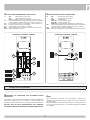
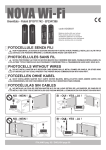
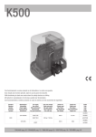
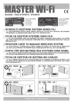
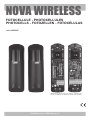
NOVA WIRELESS
FOTOCELLULE - PHOTOCELLULES
PHOTOCELLS - FOTOZELLEN - FOTOCÉLULAS
cod. ACG8047
(Batterie AA non incluse - Piles AA non incluses - AA batteries not
included - AA Batterien nicht beiliegend - Baterías AA no incluidas)
ITALIANO pag. 02 / ENGLISH pag. 07
I
SETTAGGI E COLLEGAMENTI TRASMETTITORE
SETTAGGI E COLLEGAMENTI RICEVITORE
J1
J2
JP1
JP2
JP3
JP4
BAT
DLTX
AD+
Morsetto di alimentazione 12-24V ac/dc
AD-
Morsetto di alimentazione 12-24V ac/dc
EDGE TX Morsetti per collegamento costa meccanica o
resistiva
Ponticello abilitazione/esclusione costa (di serie ponticello non
inserito per costa non collegata. Chiudere il ponticello se si
collega una costa)
Ponticello di selezione della portata (15 o 30 metri - impostazione
di fabbrica 30 m)
Ponticello selezione frequenza (2 disponibili)
Ponticello selezione modalità di alimentazione (batteria o rete)
Batterie alcaline 2 x AA 1,5V (se non viene utilizzata alimentazione
di rete)
led verde per verifica funzionamento
Morsetto di alimentazione 12-24V ac/dc
Morsetto di alimentazione 12-24V ac/dc
Comune dei contatti
Contatto normalmente chiuso
Contatto normalmente aperto
Morsetti per collegamento costa meccanica o
resistiva
JP5
Ponticello abilitazione/esclusione costa (di serie ponticello non
inserito per costa non collegata. Chiudere il ponticello se si
collega una costa)
JP6
Ponticello selezione frequenza (2 disponibili)
DLRX Led rosso per segnalare la corretta alimentazione e l’allineamento
del segnale infrarosso
SCHEMA CON POSIZIONI STANDARD DEI PONTICELLI
AD+
AD-
COM
PHOT NC
PHOT NO
EDGE RX
SCHEMA CON POSIZIONI STANDARD DEI PONTICELLI
JP5
BAT
DLTX
JP6
DLRX
JP4
JP3
J1
J2
JP2
JP1
NOTA: O
GNI VOLTA CHE SI ESEGUE UNA NUOVA CONFIGURAZIONE TRAMITE PONTICELLO E’ NECESSARIO TOGLIERE E RIDARE
ALIMENTAZIONE SIA AL TRASMETTITORE CHE AL RICEVITORE.
RIFERIMENTI
AUTOMATICI
POSSIBILITÁ DI IMPIEGO
NORMATIVI PER PORTE E CANCELLI
Le fotocellule NOVA WIRELESS, tecnologicamente all’avanguardia,
soddisfano completamente l’esigenza di una sicurezza attiva su tutti i tipi
di aperture automatiche.
Sono prodotte nella versione da parete, da fissare su colonne in ferro o
di altro materiale liscio, o su COLONNINE DI SUPPORTO DEDICATE
cod. ACG8039.
L’installatore deve assicurarsi che l’installazione delle fotocellule NOVA
WIRELESS sia fatta solo in presenza di una ulteriore protezione
principale come specificato nella norma EN12453 al punto 5.5.1. (requisiti
generali di protezione).
RIB NON PUÓ CONSIDERARSI RESPONSABILE PER
EVENTUALI DANNI CAUSATI DA UN USO IMPROPRIO,
ERRONEO O IRRAGIONEVOLE.
2
I
MONTAGGIO
CPL1311
BC08047R
BC08047T
CPL1312
CPL1940
N.B.: Prima di posizionare o incollare la dima di foratura (cod. CVA1940) controllare che la superficie di contatto sia pulita.
- Fissare le basi plastiche CPL1312 sui pilastri o sulle colonnine ad un’altezza di circa 40÷60 cm dal suolo e ad una distanza max di 10 cm dalla zona di
convogliamento o schiacciamento o subito dopo l’ingombro dato da un’eventuale costa.
- Terminate le regolazioni montare lo schermo protettivo CPL1311.
- Installate il ricevitore in ombra o in una posizione in cui il sole non possa battere orizzontalmente.
- In ogni caso si consiglia di posizionare le fotocellule alla stessa altezza e allineate tra loro.
- Per il corretto posizionamento delle fotocellule fare riferimento al manuale di installazione dell’operatore o comunque alla norma EN12445.
COLLEGAMENTI
Utilizzare cavi tipo H05RN-F con fili di
sezione minima 0,75 mm2.
Se si supera la distanza di 10 m tra
fotocellule e quadro di comando, la sezione
del filo deve essere aumentata a 1 mm2.
ATTENZIONE: Se il led del ricevitore
rimane acceso o lampeggia è possibile
che siano presenti dei disturbi sulla rete di
alimentazione.
Vi consigliamo di collegare elettricamente
verso terra le colonne o le colonnine
di supporto alle
fotocellule
al
morsetto “A/D-”
per proteggere
A/Dle fotocellule da
fonti di disturbo.
Fate attenzione
a non creare corto circuiti quando le
fasi di alimentazione sono invertite!
NOTA: E’ possibile collegare sia al ricevitore
che al trasmettitore delle coste meccaniche
o resistive come riferito nel paragrafo
“COLLEGAMENTO DI COSTE MECCANICHE
O RESISTIVE”.
Contatto N.C. da collegare ai
morsetti COM-PHOT
Non eseguire il collegamento
se si utilizza l’alimentazione
a batterie
Alimentazione 12/24V ac/dc
da collegare ai morsetti AD+
AD- presenti sulle schede RIB
3
I
12/24V ac/dc
Se si utilizza l’alimentazione a batterie, posizionare il
ponticello JP4 del trasmettitore in questa posizione:
12/24V ac/dc
Se si utilizza l’alimentazione esterna, posizionare il
ponticello JP4 del trasmettitore in questa posizione:
JP4
BATTERIE
JP4
BATTERIE
Le fotocellule NOVA WIRELESS possono essere installate vicinissime tra
di loro grazie alla funzione di SINCRONISMO.
Il SINCRONISMO è garantito per 2 coppie di fotocellule agendo sui
ponticelli JP3 per il trasmettitore e JP6 per il ricevitore come da disegno
sottostante.
TX1
RX1
FR1
JP6
JP3
FR1
TX2
RX2
FR2
JP6
JP3
FR2
PORTATA
corretta alimentazione e funzionamento. Il led dopo 10 secondi si spegne
per non consumare inutilmente l’energia delle batterie, ma la trasmissione
del segnale infrarosso continua.
È possibile decidere la portata delle fotocellule posizionando un jumper
sul/sui trasmettitore/i.
ALLINEAMENTO
Ponticello JP2 con portata regolata a 30 m (impostazione di fabbrica)
H
-L
e fotocellule NOVA WIRELESS vengono consegnate con allineamento
centrale, tuttavia in caso di necessità è possibile eseguire una regolazione
dei gruppi ottici del trasmettitore e del ricevitore (+90°/-90° in orizzontale
e +5°/-5° in verticale).
- Ad allineamento eseguito il led rosso presente sul ricevitore si deve
accendere fisso per indicare la corretta ricezione del segnale infrarosso
generato dal trasmettitore.
Se il led rosso lampeggia => significa che il segnale è debole e quindi
l’allineamento è da ottimizzare fino ad ottenere il led rosso acceso fisso.
- Se il trasmettitore ed il ricevitore sono montati ad una distanza inferiore
a 15 metri, consigliamo di posizionare il ponticello JP2 come indicato
nel paragrafo “PORTATA” in questo modo si ha un minor consumo delle
batterie con conseguente allungamento della vita delle stesse.
- Montare gli schermi protettivi.
Ponticello JP2 con portata regolata a 15 m
L
-D
opo aver fissato le basi plastiche delle fotocellule NOVA, inserire le
schede elettroniche nelle apposite sedi predisposte sulle basi e quindi
fissarle con le viti in dotazione.
- Eseguire i collegamenti elettrici come da schema.
COLLEGAMENTO BATTERIE AL TRASMETTITORE TX
VERIFICA DEL FUNZIONAMENTO
Se si desidera utilizzare l’alimentazione a batteria 1,5V, seguire le
seguenti indicazioni:
- Verificare che il ponticello JP4 sia posizionato per
l’alimentazione a batterie.
- Inserire le due batterie alcaline tipo AA da 1,5v
facendo attenzione alle polarità (si veda
immagine a lato).
Nel momento dell’inserimento delle batterie sul
trasmettitore TX il led verde si accende per 10 secondi segnalando la
FUNZIONAMENTO CON SINCRONISMO:
- Interporre un’ostacolo davanti al trasmettitore.
- Verificare che il led rosso del corrispondente ricevitore si spenga.
FUNZIONAMENTO SENZA SINCRONISMO:
- Interporre un’ostacolo prima davanti al trasmettitore e poi davanti al
ricevitore.
- Verificare che il led rosso del ricevitore si spenga in entrambi i casi.
4
I
STATO DI ATTENZIONE (avviso di sostituzione batterie)
Durante questo periodo il led rosso del ricevitore si spegne segnalando il
fermo dell’automazione.
Lo stato di attenzione avverte l’utilizzatore dell’imminente necessità di
sostituire le batterie.
Quando le batterie quasi scariche raggiungono i 2,2V, interponendo
un ostacolo oppure transitando attraverso le fotocellule, il trasmettitore
segnala al ricevitore lo stato di batterie quasi scariche. Il ricevitore attiva il
proprio BUZZER che emette un suono ogni mezzo secondo per 1 minuto.
Lo stato di attenzione (il suono del buzzer) si rinnova per 1 minuto ogni
qual volta si transiti attraverso le fotocellule.
Durante queste segnalazioni il sistema è ancora funzionante, ma è
opportuno sostituire al più presto le batterie evitando il fermo della porta
che avviene al raggiungimento dei 1,8V.
SOSTITUZIONE DELLE BATTERIE
La durata delle batterie applicate alle fotocellule NOVA WIRELESS è di
circa 3 anni.
La sostituzione delle batterie alcaline tipo AA da 1,5V è facile.
- Identificare il trasmettitore con le batterie scariche. Per far ciò è
sufficiente verificare lo stato dei ricevitori presenti nell’impianto. Se il led
rosso di un ricevitore è sempre spento, il corrispondente trasmettitore ha
le batterie scariche.
- Togliere lo schermo protettivo del trasmettitore.
- Sostituire le batterie facendo attenzione al rispetto delle polarità.
- Verificare l’accensione del led verde del trasmettitore e l’accensione del
led rosso sul ricevitore.
- Rimontare lo schermo protettivo del trasmettitore.
L’automazione può ripartire in tutta sicurezza.
ATTENZIONE: Si ricorda che le batterie vanno smaltite secondo le
Norme vigenti. In caso di rottamazione delle fotocellule, si rammenta
di togliere le batterie tipo AA e di smaltirle secondo le norme vigenti.
STATO DI ALLARME BATTERIE SCARICHE
Lo stato di allarme si attiva con batterie completamente scariche (1,8V) o
con guasto del trasmettitore della fotocellula.
L’allarme viene dato dopo 3 ore di mancata ricezione del segnale
infrarosso da parte del ricevitore.
Il buzzer del ricevitore emette un suono continuo per 1 minuto ogni 3 ore,
fino alla sostituzione delle batterie.
IN CASO DI DIFFICOLTA’
SINTOMO
VERIFICA
Il led verde DLTX del trasmettitore non si accende all’inserimento delle
batterie.
- Verificare il corretto inserimento con il rispetto delle polarità, OPPURE
- Sostituire le batterie in quanto scariche, OPPURE
- Se presente una costa collegata al trasmettitore TX e questa risulta
impegnata o guasta, verificare l’integrità dei collegamenti e dei contatti
della costa e la presenza della resistenza da 8,2kΩ.
Il led rosso DLRX del ricevitore risulta spento.
- Batterie scariche sul trasmettitore. Sostituirle, OPPURE
- Se presente una costa collegata al ricevitore e questa risulta impegnata o
guasta, verificare l’integrità dei collegamenti e dei contatti della costa e la
presenza della resistenza da 8,2kΩ.
Transitando davanti alle fotocellule il buzzer emette un tono ogni 0,5 Sostituire al più presto le batterie del/dei trasmettitori in quanto sono quasi
secondi per 1 minuto e la porta continua a funzionare.
scariche.
Il buzzer sul ricevitore emette un tono continuo per 1 minuto, e la porta
non parte.
Sostituire le batterie del/dei trasmettitori in quanto scariche.
La porta non apre.
- Fotocellula non allineata, impegnata o batterie scariche sul trasmettitore,
OPPURE
- Resistenza da 8,2 kΩ non collegata in serie al contatto N.C. o in parallelo
al contatto N.O. della costa collegata sul trasmettitore o sul ricevitore.
La costa collegata al trasmettitore o al ricevitore non funziona.
Verificare la corretta abilitazione al funzionamento della costa controllando
il ponticello JP1 sul trasmettitore e JP5 sul ricevitore.
Se i ponticelli risultano corretti staccare e ridare tensione alle fotocellule.
COLLEGAMENTO
DI COSTE MECCANICHE (TOUCH cod.
ACG3015) O RESISTIVE ALLE FOTOCELLULE NOVA WIRELESS
-C
ollegate ai morsetti EDGE TX per il trasmettitore o EDGE RX per il
JP5
ricevitore il contatto N.C. della costa.
- Posizionare sul ricevitore il ponticello JP5 nella seguente
ON
posizione per abilitare la costa.
- Posizionare sul trasmettitore il ponticello JP1 nella seguente
JP1
ON
posizione per abilitare la costa
NOTA: LA COSTE COLLEGATE ALLE FOTOCELLULE FANNO
REAGIRE IL CANCELLO COME PREVISTO PER LE FOTOCELLULE
STESSE. FATE PERTANTO ATTENZIONE A DOVE LE POSIZIONATE.
PER COSTE ELETTRICHE CON CONTATTO N.O.
- Collegate in parallelo al contatto N.O. della costa una resistenza da 8,2
KΩ (senza tale resistenza il sistema non funziona, vedere tabella “IN
CASO DI DIFFICOLTA’)
- Collegate ai morsetti EDGE TX per il trasmettitore o EDGE RX per il
JP5
ricevitore il contatto N.O. della costa.
- Posizionare sul ricevitore il ponticello JP5 nella seguente posizione
ON
per abilitare la costa.
JP1
- Posizionare sul trasmettitore il ponticello JP1 nella seguente
ON
posizione per abilitare la costa.
LE FUNZIONALITA’ DELLE COSTE APPLICATE ALLE FOTOCELLULE
SONO LE SEGUENTI:
- Se la costa viene premuta DURANTE IL MOVIMENTO DI CHIUSURA,
il cancello INVERTE IL MOVIMENTO IN APERTURA.
- Se la costa viene premuta DURANTE IL MOVIMENTO DI APERTURA, il
cancello INTERROMPE L’APERTURA FIN TANTO che rimane premuta.
AL RILASCIO della costa il cancello CONTINUA L’APERTURA.
Quest’ultimo comportamento del cancello è vincolato alle impostazioni
eseguite sulla centrale di comando.
PER COSTE MECCANICHE TOUCH (ACG3015) CON CONTATTO N.C.
- Collegate in serie al contatto N.C. della costa una resistenza da 8,2 KΩ
(senza tale resistenza il sistema non funziona. Vedere tabella “IN CASO
DI DIFFICOLTA’).
ESEGUITE UNA VERIFICA FUNZIONALE DELLE COSTE COME
SOPRA DESCRITTO.
5
I
CARATTERISTICHE TECNICHE
TRASMETTITORE NOVA WIRELESS CON FUNZIONAMENTO DA
ALIMENTAZIONE ESTERNA
- ALIMENTAZIONE
12-24V ac/dc Verificate la
compatibilità con l’alimentazione
fornita dal quadro elettronico.
- ASSORBIMENTO MASSIMO
20 mA
- LED VERDE
sempre acceso
- PORTATA SELEZIONABILE
15 o 30 m (con buone condizioni
atmosferiche)
N.B.: La portata si può ridurre
in presenza di fenomeni
atmosferici quali nebbia,
pioggia, polvere, ecc.
RICEVITORE NOVA WIRELESS
- ALIMENTAZIONE
2-24V ac/dc (Verificate la
1
compatibilità con l’alimentazione
fornita dal quadro elettronico)
- ASSORBIMENTO MASSIMO
110 mA
- PORTATA RELE’
1A - 30 V dc
- TEMPO DI ECCITAZIONE RELE’ 120 mS
- LED ROSSO
acceso => RICEVITORE allineato.
(N.B. a taratura avvenuta si
spegne quando si interpone un
ostacolo)
TRASMETTITORE NOVA WIRELESS CON FUNZIONAMENTO A
BATTERIE
- ALIMENTAZIONE
batterie alcaline 2 x AA 1,5V
(>2,7Ah)
- ASSORBIMENTO
3 µA
- VITA DELLE BATTERIE
circa 3 anni
- VITA BATTERIE CON JUMPER JP2 IN POSIZIONE PORTATA 15 m
4 anni
- VITA BATTERIE CON JUMPER JP2 IN POSIZIONE PORTATA 30 m
3 anni
- LED VERDE
acceso => il trasmettitore è
alimentato (questa segnalazione
è attiva solo per i primi 10 secondi
dall’inserimento batterie).
- PORTATA SELEZIONABILE
15 o 30 m (con buone condizioni
atmosferiche)
N.B.: La portata si può ridurre
in presenza di fenomeni
atmosferici quali nebbia,
pioggia, polvere, ecc.
CARATTERISTICHE TECNICHE COMUNI
- SEGNALE INFRAROSSO
LUNGHEZZA D’ONDA 890 nm
- TEMPERATURA DI LAVORO
-20°C ÷ +60°C
- CONTENITORE
esterno in policarbonato
interno in abs
- GRADO DI PROTEZIONE
IP44
- DIMENSIONI
150x45x41
- PESO
0,300 kg
OPTIONAL
COPPIA COLONNINE NOVA
H = 0,5 m
COSTA MECCANICA TOUCH
cod. ACG8039
L = 2 m - Certificata EN 13849-2 (2008) - Categoria 3
cod. ACG3015
BATTERIE ALCALINE AA
BATTERIE LITHIO AA
4 X 1,5V - con NOVA WIRELESS durata batterie 3÷4 anni.
cod. ACG9519
2 X 1,5V - con NOVA WIRELESS durata batterie 4÷5 anni.
Per temperature estreme -40÷+60°C.
cod. ACG9509
6
G
B
SETTINGS AND TRANSMITTER CONNECTIONS
SETTINGS AND RECEIVER CONNECTIONS
J1
JP1
J2
JP5
JP2
JP3
JP4
BAT
DLTX
AD+
Feed terminal 12-24V ac/dc
AD-
Feed terminal 12-24V ac/dc
EDGE TX Feed terminals for mechanical or resistive strip
Strip enabling/disabling jumper (standard jumper not inserted for
unconnected strip. Disable the jumper if a strip is connected)
Range selector jumper (15 or 30 meters - factory setting 30 m)
Frequency selector jumper (2 available)
Power selector jumper (battery or network)
Alkaline batteries 2 x AA 1,5V (if network power is not used)
Green LED function indicator
AD+
Feed terminal 12-24V ac/dc
AD-
Feed terminal 12-24V ac/dc
COM
Contact system
PHOT NC Contact normally closed
PHOT NO Contact normally open
EDGE RX Feed terminals for mechanical or resistive strip
Strip enabling/disabling jumper (standard jumper not inserted for
unconnected strip. Disable the jumper if a strip is connected)
JP6
Frequency selector jumper (2 available)
DLRX Red LED indicating correct power and infrared signal alignment
STANDARD POSITIONS JUMPERS
STANDARD POSITIONS JUMPERS
JP5
BAT
DLTX
JP6
DLRX
JP4
JP3
J1
J2
JP2
JP1
NOTE: E
ACH TIME A NEW JUMPER CONFIGURATION IS USED IT IS NECESSARY TO TURN OFF AND TURN ON POWER TO BOTH THE
TRANSMITTER AND THE RECEIVER.
REFERENCE
AND DOORS
USES
TO STANDARDS FOR AUTOMATIC GATES
NOVA WIRELESS photocells are technologically advanced and
completely meet the active security demands of all types of automatic
opening systems.
They are produced in versions for wall mounting, for mounting to columns
of iron or other smooth material, or on dedicated SUPPORT COLUMNS
cod. ACG8039.
The installer must ensure that the installation of the NOVA WIRELESS
photocells is performed only in the presence of further protection as
specified by standard EN12453 in 5.5.1. (general protection requirements).
RIB MAY NOT BE HELD RESPONSIBLE FOR DAMAGES
CAUSED BY IMPROPER, WRONG OR UNREASONABLE USE.
7
G
B
MOUNTING
CPL1311
BC08047R
BC08047T
CPL1312
CPL1940
N.B.: Before placing the drilling template (code CVA1940) make sure that the contact surface is clean.
- Affix the plastic bases CPL1312 to the pillars or columns about 40÷60 cm from the ground and at a maximum distance of 10 cm from the conveyance
or pressure area or immediately out of range of any protruding edge.
- After adjustment attach the protective casing CPL1311.
- Install the receiver in a shaded area or in a position not exposed to horizontal sunlight.
- In every case it is advisable to place the photocells at the same height and in line with each other.
- For the correct positioning of the photocells refer to the user installation manual or to standard EN12445.
CONNECTIONS
Use H05RN-F cables, with a minimum
section of 0,75 mm2.
If you exceed the distance of 10 m between
photocells and control panel, the wire
section must be increased to 1 mm2.
ATTENTION: In case the receiver led
remains lit, malfunctioning of the main
supply is suspected.
It is advisable
to
connect
electrically the
photocells stands
A/Dto the contact
“A/D-”, to shield
the
photocells
from external noise.
Be careful not to short circuit the system
when the supply phases are inverted!
NOTE: It is possible to connect both the
transmitter and the receiver to mechanical
or resistive strips as shown in the paragraph
“CONNECTION OF MECHANICAL OR
RESISTIVE STRIP”.
Contact N.C. to connect to
terminals COM-PHOT
Power 12/24V ac/dc to
connect to terminals AD+ ADon the RIB control panels
Do not perform the connection
when using battery power.
8
G
B
12/24V ac/dc
If battery power is used, place the transmitter jumper JP4
in this position:
12/24V ac/dc
If an external power source is used, place the transmitter
jumper JP4 in this position.
JP4
BATTERIE
JP4
BATTERIE
NOVA Wi-Fi photocells may be installed very close together thanks to
SYNCHRONIZATION.
SYNCHRONIZATION is guaranteed for up to 2 pairs of photocells working
on the jumpers JP3 for the transmitter and JP6 for the receiver as shown
below.
TX1
RX1
FR1
JP6
JP3
FR1
TX2
RX2
FR2
JP6
JP3
FR2
RANGE
ALIGNMENT
-N
OVA WIRELESS photocells are packaged with central alignment
however, if necessary, it is possible to adjust the optical units of the
transmitter and receiver (+90°/-90° horizontally and +5°/-5° vertically).
- After performing the alignment the red LED on the receiver must emit a
constant light to indicate correct reception of the infrared signal from the
transmitter. If the red LED is flashing it means that the signal is weak and
that the alignment must be improved until the red LED emits a constant
light.
- If the transmitter and the receiver are mounted at a distance of less than
15 meters, we recommend positioning the jumper JP2 as indicated in the
paragraph “RANGE”. This will provide lower battery consumption and
consequently add to their duration.
- Mount the protective cover.
It is possible to adjust the range of the photocells by placing a jumper on
the transmitter(s).
Jumper JP2 with a range of 30 m (factory setting)
H
Jumper JP2 with a range of 15 m
L
-A
fter affixing the plastic bases of the NOVA WIRELESS photocells, insert
the circuit boards into the proper places on the bases and attach them
with the supplied screws.
- Make the electrical connections as in the diagram.
SYSTEM CHECK
SYNCHRONIZATION:
- Place an object in front of the transmitter.
- Check that the red LED of the corresponding receiver turns off.
NO SYNCHRONIZATION:
- Place an object in front of the transmitter and then in front of the receiver.
- Check that the red LED of the receivers is off in both cases.
CONNECTING THE BATTERY TO THE TRANSMITTER TX
If 1,5V battery power is desired, follow these instructions:
- Check that jumper JP4 is set for battery power.
- Insert the two AA 1,5V Alkaline batteries checking
that the polarity is correct (see side image).
Upon insertion of the batteries into the transmitter TX
the green LED will light for 10 seconds indicating that
it works correctly. The LED then shuts off so as not to
waste battery energy, but the infrared signal is active.
9
G
B
WARNING (replace the batteries)
The WARNING tells the user of the immediate need to replace the
batteries.
When battery power reaches 2,2V, placing or moving an object between
the photocells causes the transmitter to signal the receiver of the low
battery status. The receiver activates the BUZZER which emits a sound
every half second for 1 minute.
The warning (the sound of the buzzer) is renewed for 1 minute every time
something passes between the photocells.
The system is still operational during these signals, but it is advantageous
to replace the batteries as soon as possible in order to avoid a full stop of
the door operation which happens when the batteries reach 1,8V.
LOW BATTERY ALARM
The alarm activates when the batteries have been exhausted (1,8V) or
when a photocell is not working.
The alarm sounds 3 hours after the loss of the infrared signal by the
receiver.
The receiver buzzer emits a continuous sound for 1 minute every 3 hours,
until the batteries have been replaced.
During this time the red LED of the receiver shuts off signaling the stop
of automation.
CHANGING THE BATTERIES
The duration of the batteries used for NOVA WIRELESS photocells is
about 3 years.
Replacing the Alkaline batteries AA 1,5V is easy.
- Identify the transmitter with the exhausted batteries. To do this simply
check the status of the system receiver. If the red LED of a receiver is
always off, the batteries of the corresponding transmitter are exhausted.
- Remove the protective cover from the transmitter.
- Replace the batteries checking that the polarity is correct.
- Check that the green LED of the transmitter and the red LED of the
receiver are on.
- Replace the protective cover on the transmitter.
L’automazione può ripartire in tutta sicurezza.
ATTENTION: Please remember that batteries must be disposed of
properly according to current standards. In case of disposal of the
photocells please remember to remove the AA batteries and dispose
of them properly.
IN CASE OF DIFFICULTY
PROBLEM
CHECK
The green LED DLTX of the transmitter does not come on when the battery
is inserted.
- Check that the polarity of the batteries is correct, or
- Replace exhausted batteries, or
- If a strip is connected to the transmitter TX and this is stuck or not working,
check the strip contacts and connections and the presence of resistance of
8,2kΩ.
The red LED DLRX of the receiver does not come on.
- Transmitter batteries are exhausted. Replace them or
- If a strip is connected to the receiver and this is stuck or not working, check the
sensor contacts and connections and the presence of resistance of 8,2kΩ.
Moving in front of the photocells the buzzer emits a sound every 5 second for
1 minute and the door continues to function.
Replace the batteries of the transmitter(s) as they are exhausted.
The receiver buzzer emits a continuous sound for 1 minute and the door does
not move.
Replace the batteries of the transmitter(s) as they are exhausted.
The door does not open.
- The photocell is not aligned, stuck or the transmitter has exhausted batteries,
or
- Resistance of 8,2 kΩ is not connected in series to the N.C. contact or in
parallel to the N.O. contact of the strip connected to the transmitter or receiver.
The strip connected to the transmitter or receiver does not work.
Check the correct operation enabling of the sensor by checking jumper JP1 on
the transmitter and JP5 on the receiver.
If the jumpers are correct turn off and then turn on power to the photocells.
CONNECTION OF THE MECHANICAL (TOUCH code ACG3015)
OR RESISTIVE TRIPS TO THE NOVA WIRELESS PHOTOCELLS
NOTE: THE STRIPS CONNECTED TO THE PHOTOCELLS MAKE
THE DOOR REACT AS TO THE PHOTOCELLS THEMSELVES.
THEREFORE PAY ATTENTION TO WHERE THEY ARE POSITIONED.
THE FUNCTIONALITY OF THE STRIPS APPLIED TO THE
PHOTOCELLS ARE AS FOLLOWS:
- if activated while the door is CLOSING => REVERSES THE OPENING
MOVEMENT;
- if activated while the door is OPENING => INTERRUPTS THE OPENING
MOVEMENT for the time that it is held. Upon being RELEASED the door
continues to open.
The latter behavior of the door depends on the setting of the control panel.
FOR TOUCH (ACG3015) MECHANICAL STRIPS WITH CONTACT N.C.
- Connect in series to the N.C. contact of the strip a resistance of 8,2 KΩ
(without this resistance the series will not work and the alarm will come
on - see table “TROUBLESHOOTING’)
-C
onnect the strip N.C. contact to the feed terminals EDGE TX for the
JP5
transmitter or EDGE RX for the receiver.
- Place the jumper JP5 on the receiver in the following position to
ON
enable the strip:
JP1
- Place the jumper JP1 on the transmitter in the following
ON
position to enable the strip:
FOR RESISTIVE STRIPS WITH N.O. CONTACT
- Connect in parallel to the N.O. contact of the strip a resistance of 8,2 KΩ
(without this resistance the series will not work and the alarm will come
on - see table “TROUBLESHOOTING’)
- Connect the strip N.O. contact to the feed terminals EDGE TX for the
JP5
transmitter or EDGE RX for the receiver.
- Place the jumper JP5 on the receiver in the following position to
ON
enable the strip:
JP1
- Place the jumper JP1 on the transmitter in the following
ON
position to enable the strip:
PERFORM A SYSTEM CHECK ON THE SENSORS AS INDICATED
ABOVE.
10
G
B
TECHNICAL SPECIFICATIONS
NOVA WIRELESS RECEIVER
- POWER NOVA WIRELESS EXTERNALLY POWERED TRANSMITTER
- POWER 12-24V ac/dc (Check
compatibility of power supplied
by the electric panel)
- MAXIMUM ABSORPTION
20 mA
- GREEN LED
always on
- ADJUSTABLE RANGE
15 o 30 m (in good weather
conditions)
N.B.: Range may be reduced in
bad weather conditions such as
fog, rain, dust, etc.
2-24V ac/dc (Check
1
compatibility of power supplied
by the electric panel)
110 mA
1A - 30 V dc
120 mS
on => RECEIVER aligned.
(N.B. when adjusted it turns off
when an object is placed in front
of it)
MAXIMUM ABSORPTION
RELAY RANGE
RELAY STROKE TIME RED LED
NOVA WIRELESS BATTERY OPERATED TRANSMITTER
- POWER
alkaline batteries 2 x AA
1,5V(>2,7Ah)
- POWER ABSORBED
3 µA
- BATTERY LIFE
about 3 years
- BATTERY LIFE WITH JP2 SET ON 15 m RANGE
4 years
- BATTERY LIFE WITH JP2 SET ON 30 m RANGE
3 years
- GREEN LED
on => the transmitter is aligned
(this signal is only active for the
first 10 seconds after the batteries
have been inserted).
- ADJUSTABLE RANGE
15 o 30 m (in good weather
conditions)
N.B.: Range may be reduced in
bad weather conditions such as
fog, rain, dust, etc.
COMMON TECHNICAL SPECIFICATIONS
- INFRARED SIGNAL
WAVELENGTH 890 nm
- OPERATING TEMPERATURE
-20°C ÷ +60°C
- CONTAINER
exterior in polycarbonate
internal in abs
- PROTECTION LEVEL
IP44
- DIMENSIONS
150x45x41
- WEIGHT
0,300 kg
ACCESSORIES
PAIR OF COLUMNS for NOVA
H = 0,5 m
TOUCH MECHANICAL STRIP
code ACG8039
L = 2 m - Certified EN 13849-2 (2008) - Category 3
AA ALKALINE BATTERIES
code ACG3015
AA LITHIO BATTERIES
4 X 1,5V - battery life with NOVA WIRELESS 3÷4 years.
2 X 1,5V - battery life with NOVA WIRELESS 4÷5 years.
For extreme temperatures -40÷+60°C.
code ACG9509
code ACG9519
11
NOVA WIRELESS
DICHIARAZIONE DI CONFORMITÁ - DÉCLARATION DE CONFORMITÉ
DECLARATION OF COMPLIANCE - DECLARACIÓN DE CONFORMIDAD
Dichiariamo sotto la nostra responsabilità che NOVA WIRELESS è conforme alle seguenti norme e Direttive:
NOVA WIRELESS se conforme aux normes suivantes:
We declare under our responsibility that NOVA WIRELESS is conform to the following standards:
Wir erklaeren das NOVA WIRELESS den folgenden EN-Normen entspricht:
Declaramos bajo nuestra responsabilidad que NOVA WIRELESS ed conforme a la siguientes normas y disposiciones:
EN 12978
EN 55014-1
EN 55014-2
EN 60335-1
2003
2000
1997
2008
EN 61000-3-2
EN 61000-3-3
EN 61000-6-1
EN 61000-6-2
2007
1997
2007
2006
EN 61000-6-3
EN 61000-6-4
2007
2007
Come richiesto dalle seguenti Direttive - Conformément aux Directives
As is provided by the following Directives - Gemaß den folgenden Richtlinien
Tal y como requerido por las siguientes Disposiciones:
2006/95/CE
2004/108/CE
Il presente prodotto non può funzionare in modo indipendente ed è destinato ad essere incorporato in un impianto costituito da ulteriori elementi.
Rientra perciò nell’Art. 6 paragrafo 2 della Direttiva 2006/42/CE (Macchine) e successive modifiche, per cui segnaliamo il divieto di messa in
servizio prima che l’impianto sia stato dichiarato conforme alle disposizioni della Direttiva.
Le présent dispositif ne peut fonctionner de manière indépendante, étant prévu pour être intégré à une installation constituée d’autres éléments. Aussi
rentre-t-il dans le champ d’application de l’art. 6, paragraphe 2 de la Directive machines 2006/42/CEE et de ses modifications successives. Sa mise
en service est interdite avant que l’installation ait été déclarée conforme aux dispositions prévues par la Directive.
This product can not work alone and was designed to be fitted into a system made up of various other elements. Hence, it falls within Article 6,
Paragraph 2 of the EC-Directive 2006/42 (Machines) and following modifications, to which respect we point out the ban on its putting into service
before being found compliant with what is provided by the Directive.
Dieses Produkt kann nicht allein funktionieren und wurde konstruiert, um in einen von anderen Bestandteilen zusammengesetzten System eingebaut
zu werden. Das Produkt fällt deswegen unter Artikel 6, Paragraph 2 der EWG-Richtlinie 2006/42 (Maschinen) und folgenden.
El presente producto no puede funcionar de manera independiente y está destinado a ser incorporado en un equipo constituido por ulteriores
elementos. Entra por lo tanto en el Art. 6 párrafo 2 de la Directiva 2006/42/CEE (Máquinas) y sucesivas modificaciones, por lo que señalamos la
prohibición de puesta en servicio antes de que el equipo haya sido declarado conforme con las disposiciones de la Directiva.
Legal Representative
(Rasconi Antonio)
25014 CASTENEDOLO (BS) - ITALY
Via Matteotti, 162
Tel. +39.030.2135811
Fax +39.030.21358279
www.ribind.it - [email protected]
Cod. CVA1969 - 20032012 - Rev. 06
Questo prodotto è stato completamente progettato e costruito in Italia · Ce produit a été complètement développé et fabriqué en Italie · This product has been completely
developed and built in Italy · Dieses Produkt wurde komplett in Italien entwickelt und hergestellt · Artìculo totalmente proyectado y producido en Italia