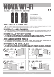
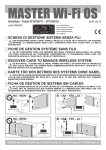
Download MASTER Wi-Fi
Transcript
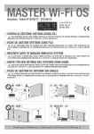
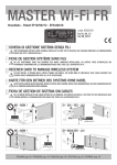
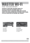
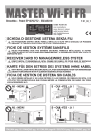
MASTER Wi-Fi
Brevettato - Patent EP10706772 - EP2345019
code ACG6094
code ACG6099
con innesto
embrochable
with connector
mit Verbinder
con conector
con morsettiera
avec bornes à visser
with terminal block
mit Endblockierung
con regleta
I
SCHEDA DI GESTIONE SISTEMA SENZA FILI
F
FICHE DE GESTION SYSTÈME SANS FILS
G
B
D
E
S
NON POSIZIONARE DIETRO A MURI, PANNELLI METALLICI O ALTRI TIPI DI OSTACOLI CHE POSSANO
IMPEDIRE LA COMUNICAZIONE RADIO CON TUTTI I DISPOSITIVI Wi-Fi
NE LES POSITIONNEZ DONC PAS DERRIÈRE DES MURS, PANNEAUX MÉTALLIQUES, OU AUTRES
TYPES D’OBSTACLES QUI POURRAIENT COMPROMETTRE LA TRANSMISSION RADIO AVEC TOUS LES
DISPOSITIFS Wi-Fi.
RECEIVER CARD TO MANAGE WIRELESS SYSTEM
DO NOT INSTALL IT BEHIND WALLS, METAL FRAMES OR PANELS, OR OTHER KIND OF OBSTACLES
THAT COULD PREVENT THE PROPER RADIO COMMUNICATION WITH ALL Wi-Fi ACCESSORIES.
KARTE FÜR DEN BETRIEB DES SYSTEMS OHNE KABEL
NICHT INSTALLIEREN HINTER MAUERN, METALLPLATTEN ODER ANDERE ARTEN VON HINDERNISSEN,
DIE DEN FUNKVERKEHR MIT Wi-Fi ZUBEHÖR BEEINTRÄCHTIGEN KÖNNEN.
FICHA DE GESTION DE SISTEMA SIN CABLES
NO LO DEBEN INSTALAR EN UN LUGAR DETRÁS DE LAS PAREDES, DE PANELES DE METAL O DE
OTRO TIPO DE OBSTÁCULOS QUE PUEDAN IMPEDIR LA COMUNICACIÓN POR RADIO CON TODOS
LOS ACCESSORIOS Wi-Fi.
NO - NEIN !
SI - OUI - YES - JA !
MASTER Wi-Fi
MASTER Wi-Fi
NO - NEIN !
SI - OUI - YES - JA !
MASTER Wi-Fi
MASTER Wi-Fi
ITALIANO pag. 02 / ENGLISH pag. 10
I
SUN 2CH
Cod. ACG6052
SUN 4CH
Cod. ACG6054
SUN CLONE 2CH
Cod. ACG6056
SUN CLONE 4CH
Cod. ACG6058
NOVA Wi-Fi
Cod. ACG8037
BLOCK Wi-Fi
Cod. ACG6098
SPARK Wi-Fi
Cod. ACG7064
VERTIGO 8
Cod. ACG8042
VERTIGO 10
Cod. ACG8043
TOUCH Wi-Fi
Cod. ACG3016
TX RED
Cod. ACG6202
SICUREZZE
Il SISTEMA Wi-Fi è conforme alla norma EN13849-2:2008 e
congiuntamente ad un quadro elettronico RIB è un dispositivo di
protezione di Classe 2.
Il SISTEMA Wi-Fi permette la realizzazione tramite la scheda
MASTER Wi-Fi di un impianto con fotocellule NOVA Wi-Fi e coste
TOUCH Wi-Fi fissate anche sull’anta in movimento senza l’adozione
di sistemi raccogli cavo.
Il sistema verifica costantemente la presenza dei vari dispositivi di
sicurezza e dello stato delle batterie, soddisfacendo completamente
l’esigenza di una sicurezza attiva su tutti i tipi di aperture.
Utilizzando i quadri elettronici RIB è possibile eseguire l’autotest del
sistema come richiesto dalle norme in vigore.
Ogni dispositivo di sicurezza radio ha un proprio codice identificativo
interno che lo distingue dagli altri.
RIFERIMENTI
AUTOMATICI
TOUCH
Cod. ACG3015
o costa di altra
marca meccanica o
resistiva
MASTER Wi-Fi può gestire fino a 6 sicurezze (NOVA Wi-Fi + VERTIGO +
TOUCH Wi-Fi + TX RED) simultaneamente.
- Fotocellule NOVA Wi-Fi (cod. ACG8037): hanno la possibilità di
collegare una costa meccanica TOUCH (cod. ACG3015) o una costa
resistiva sia sulla fotocellula trasmettitore, sia sulla fotocellula ricevitore.
- Fotocellule VERTIGO (VERTIGO 8 cod. ACG8042 - VERTIGO 10 cod.
ACG8043): fotocellule verticali senza fili sostitutive della costa.
- Costa TOUCH Wi-Fi (cod. ACG3016), con ricetrasmettitore incorporato.
- TX RED (cod. ACG6202): trasmettitore per gestire via radio coste
meccaniche o resistive.
COMANDI
MASTER Wi-Fi gestisce fino a 100 codici diversi dei telecomandi:
- Telecomandi SUN bicanali 433,92 MHz (cod. ACG6052)
- Telecomandi SUN quadricanali 433,92 MHz (cod. ACG6054)
- Telecomandi SUN CLONE bicanali 433,92 MHz (cod. ACG6056)
- Telecomandi SUN CLONE quadricanali 433,92 MHz (cod. ACG6058)
- Selettore a chiave BLOCK Wi-Fi monocanale 433,92 MHz (cod.
ACG6098).
E’ possibile collegare comandi filari con contatto N.O. (selettori a chiave,
pulsantiere, ecc).
NORMATIVI PER PORTE E CANCELLI
L’installatore deve assicurarsi che il SISTEMA Wi-Fi sia collegato come
specificato nella norma EN12453 al punto 5.1.1.6 (punti e ed f) ad una
centrale elettronica in grado di effettuare un controllo del funzionamento
prima di effettuare il movimento di chiusura (AUTOTEST).
Utilizzare quindi i dispositivi RIB permette di realizzare un’installazione
conforme alle Norme e Direttive in vigore.
Una volta ultimata l’installazione della macchina ci si deve sincerare che
sia conforme alla norma EN13241-1.
RIB non puó considerarsi responsabile per eventuali danni causati da un
uso improprio, erroneo o irragionevole del prodotto.
SEGNALAZIONI VISIVE
MASTER Wi-Fi può gestire uno o più lampeggiatori SPARK Wi-Fi (868,3
MHz) cod. ACG7064.
MASTER Wi-Fi possiede dei led per il monitoraggio dello stato del
sistema e per l’identificazione delle fotocellule o delle coste con batterie
quasi scariche o scariche.
MASTER Wi-Fi
E’ il cuore del sistema: gestisce tutti i dispositivi di comando (433,92
MHz), di sicurezza e di segnalazione (868,3 MHz) programmati in fase
di installazione.
MASTER Wi-Fi è disponibile in 4 modelli:
- MASTER Wi-Fi con connettore (cod. ACG6094), applicabile a tutti i
quadri elettronici RIB non CRX.
- MASTER Wi-Fi con morsettiera (cod. ACG6099), applicabile a quadri
di altre marche o RIB CRX.
- MASTER Wi-Fi FR con morsettiera (cod. ACG6150), applicabile a
quadri di altre marche o RIB CRX.
- MASTER Wi-Fi OS con morsettiera (cod. ACG6152), applicabile a
quadri di altre marche o RIB CRX.
SEGNALAZIONI ACUSTICHE
MASTER Wi-Fi possiede un buzzer che segnala le fasi di installazione
e lo stato di attenzione in caso di batterie quasi scariche e scariche o lo
stato di allarme in caso di guasto di uno dei dispositivi.
2
I
A - PREDISPOSIZIONE IMPIANTO
Il sistema Wi-Fi può essere installato su diverse tipologie di automazione (escluso le barriere automatiche). Di seguito indichiamo alcune possibilità.
SCORREVOLE
BATTENTE
MASTER Wi-Fi
MASTER Wi-Fi
BASCULANTE
SEZIONALE/SERRANDA
MASTER Wi-Fi
MASTER Wi-Fi
B - MONTAGGIO DISPOSITIVI DI PROTEZIONE
FOTOCELLULE NOVA Wi-Fi
- Fissare le fotocellule NOVA Wi-Fi, sui pilastri o sulle colonnine ad
un’altezza di circa 40÷60 cm dal suolo e ad una distanza max di 10 cm
dalla zona di convogliamento o schiacciamento o subito dopo l’ingombro
dato da un’eventuale costa, a max 20 metri di distanza dal MASTER
Wi-Fi.
- Installate il ricevitore in ombra o in una posizione in cui il sole non possa
battere orizzontalmente.
- In ogni caso si consiglia di posizionare le fotocellule alla stessa altezza
e allineate tra loro.
- Per il corretto posizionamento delle fotocellule fare riferimento al loro
manuale d’installazione o comunque alla norma EN12445.
COSTE TOUCH Wi-Fi
- Fissare le coste TOUCH Wi-Fi nelle zone di convogliamento o
schiacciamento a max 20 metri di distanza dal MASTER Wi-Fi.
TX RED
- Collegare il trasmettitore alla costa a max 20 metri di distanza dal
MASTER WI-Fi.
LAMPEGGIATORE SPARK Wi-Fi
- Fissare il lampeggiatore SPARK Wi-Fi a max 20 metri di distanza dal
MASTER Wi-Fi, in modo che sia visibile.
FOTOCELLULE VERTIGO
- Fissare le fotocellule VERTIGO nelle zone di convogliamento o
schiacciamento a max 20 metri di distanza dal MASTER Wi-Fi.
ATTENZIONE:
Se viene tolta l’alimentazione del MASTER Wi-Fi per un periodo di tempo prolungato le coste TOUCH Wi-Fi, le fotocellule
NOVA Wi-Fi e le fotocellule VERTIGO esauriranno più velocemente del normale la carica delle loro batterie. Tenere i MASTER
Wi-Fi sempre correttamente alimentati per garantire la durata di 3 anni delle batterie come dichiarata da RIB.
Se per esempio viene tolta la tensione al cancello tutte le notti, fotocellule e coste “cercano” ripetutamente il segnale dal
MASTER Wi-Fi senza trovarlo e quindi la durata delle batterie di questi accessori si riduce a meno di un anno.
3
I
C - LAYOUT SCHEDA
S1
SW1
JP1
JP2
Led bicolore
EDGE PHOT 1-6
J8
J4
J1
BUZZER
J2
12/24V ac/dc
10 9
65
21
10 9 6 56 45J5
3 2211
+ -
+ +- -
MASTER Wi-Fi cod. ACG6094
1
centrale antenna 433
2
massa antenna
3-4 liberi
5
alimentazione negativa a 12/24V ac/dc
6
alimentazione positiva a 12/24V ac/dc
7-8 liberi
9-10 comando per apertura/chiusura totale
J1 =>
ONNETTORE PER COLLEGAMENTI AL QUADRO DI COMANDO,
C
AGLI INGRESSI DI COMANDI E SICUREZZE
Filo verde => comando pedonale PED
Filo grigio => comune dei contatti COM
Filo giallo => costa EDGE
Filo nero
=> fotocellula PHOT N.C.
Filo bianco => morsetto a cui collegare il filo proveniente dal
pulsante N.O. di comando già presente nell’impianto
Filo marrone => alimentazione autotest A-D+ TEST.
J2 => CONNETTORE PER COLLEGAMENTI AL QUADRO
DI COMANDO A 12/24V ac/dc, ALL’USCITA DEL
LAMPEGGIATORE (ATTENZIONE ALLE POLARITA’)
Filo rosso => positivo (da collegare al polo positivo dell’uscita
lampeggiatore)
Filo nero => negativo (da collegare al polo negativo dell’uscita
lampeggiatore)
J4 => MORSETTI PER COLLEGAMENTI AL QUADRO DI COMANDO
120/230V, ALL’USCITA LAMPEGGIATORE
J5 => CONNETTORE FEMMINA PER INNESTO SU QUADRI DI
COMANDO RIB NON CRX (MASTER Wi-Fi cod. ACG6094) O
MORSETTIERA PER COLLEGAMENTI SU QUADRI DI COMANDO
DI ALTRE MARCHE O RIB CRX (MASTER Wi-Fi cod. ACG6099)
J8 => MORSETTO PER COLLEGAMENTO ANTENNA 868,3 MHz
JP1 => A/D+ TEST vedere tabella TABELLA QUADRI ELETTRONICI RIB
ABILITATI AL CONTROLLO AUTOTEST
-
Jumper selezione modalità AUTOTEST per quadri di comando non
RIB con alimentazione AUTOTEST negativa
+/~
Jumper selezione modalità AUTOTEST per quadri di comando RIB
JP2 => Abilitazione cancellazione codici radio per apertura totale e
pedonale
654321
+ -
MASTER Wi-Fi con morsettiera cod. ACG6099
1 centrale antenna 433
2 massa antenna
3 alimentazione negativa a 12/24V ac/dc
4 alimentazione positiva a 12/24V ac/dc
5-6 da collegare alla centrale di comando
all’ingresso del pulsante di apertura/chiusura
totale (K BUTTON se quadro RIB)
SW1 =>
Microinterruttori
di abbinamento e identificazione coste e
fotocellule
S1 =>
PROG. RX Pulsante per programmazione
BUZZER => Segnalazione sonora per stati di installazione, attenzione e
allarme
LED
DL1 (rosso) - comando apertura pedonale N.O. (PED)
DL2 (rosso) - contatto coste N.C. (EDGE)
DL3 (rosso) - contatto fotocellule N.C. (PHOTO)
DL4 (rosso) - comando apertura totale con pulsante N.O. già presente
nell’impianto
DL5 (verde) - comando radio apertura totale attivato.
DL6 (giallo) - presenza tensione di alimentazione 12-24V ac/dc
DL7 (bicolore) - apprendimento codici radio per apertura totale e pedonale e
lampeggiatore
LED BICOLORE EDGE PHOT
spento
=> funzionamento regolare
verde
=> costa o fotocellula impegnata
rosso/verde => allarme
LED EDGE PHOT 1 - COSTA O FOTOCELLULA 1
LED EDGE PHOT 2 - COSTA O FOTOCELLULA 2
LED EDGE PHOT 3 - COSTA O FOTOCELLULA 3
LED EDGE PHOT 4 - COSTA O FOTOCELLULA 4
LED EDGE PHOT 5 - COSTA O FOTOCELLULA 5
LED EDGE PHOT 6 - COSTA O FOTOCELLULA 6
SW1 MICROINTERRUTTORI - DIP
DIP 1 ON => COSTA O FOTOCELLULA 1 ATTIVATA
DIP 2 ON => COSTA O FOTOCELLULA 2 ATTIVATA
4
I
DIP 3 ON =>
DIP 4 ON =>
DIP 5 ON =>
DIP 6 ON =>
COSTA O FOTOCELLULA 3 ATTIVATA
COSTA O FOTOCELLULA 4 ATTIVATA
COSTA O FOTOCELLULA 5 ATTIVATA
COSTA O FOTOCELLULA 6 ATTIVATA
ATTENZIONE: Ogni volta che si esegue un cambio di posizione dei
microinterruttori, premere il tasto PROG RX per 6 volte in modo da
aggiornare la programmazione del sistema. Al termine i led bicolore
devono risultare tutti spenti.
D - COLLEGAMENTO DELLA SCHEDA MASTER Wi-Fi
ATTENZIONE: L’uso del prodotto all’interno di contenitori in metallo può generare un malfunzionamento del sistema. Si consiglia quindi
in questi casi di aggiungere l’antenna cod. ACG5451 da applicare sul carter metallico per una perfetta ricezione/trasmissione dei segnali.
ATTENZIONE: UTILIZZANDO MASTER Wi-Fi CON QUADRI DI ALTRE MARCHE È IMPORTANTE ATTIVARE SU QUELLE CENTRALI DI
COMANDO LA FUNZIONE DI PRELAMPEGGIO (SE DISPONIBILE).
Si consiglia di memorizzare sulla scheda comando motore un tempo di chiusura automatica non superiore ad un minuto.
Normalmente la scheda MASTER Wi-Fi quando innestata su quadri elettronici RIB, è protetta contro i corto circuiti tramite fusibile collegato in serie al secondario di
alimentazione.
In caso si utilizzi la scheda MASTER Wi-Fi con altri quadri elettronici verificare la presenza della protezione. In caso non sia presente, collegare in serie
all’alimentazione un fusibile ritardato (T) da 200 mA.
- Togliere tensione al quadro di comando dell’automazione.
- Collegare la scheda MASTER Wi-Fi come indicato qui di seguito.
NOTA: l’apertura del cancello avviene circa 2 secondi dopo che si è dato un comando da pulsante. Questo per consentire alla scheda MASTER Wi-Fi di verificare la
presenza ed il corretto funzionamento delle sicurezze memorizzate.
*
120/230V ac
PED
filo verde
COM
filo grigio
EDGE
filo giallo
PHOT.N.C. filo nero
PULSANTE DI COMANDO
filo bianco
A/D+ TEST filo marrone
!
+
12/24V ac/dc
10 9
65
Il Sistema Wi-Fi funziona regolarmente
se gestisce lui tutti i comandi radio
(tramite il suo modulo radio 433MHz) e
filari (tramite il suo filo bianco).
In caso di utilizzo di radio ricevitori
e comandi filari già esistenti (quindi
esterni al Sistema Wi-Fi), per un
regolare funzionamento collegarli al
filo bianco del MASTER Wi-Fi.
21
654321
+ -
!
+ 6
5
Contatto comando
apertura totale
COM-OPEN/K
4+ 3Alimentazione
12/24V ac/dc
-
**
12/24V ac/dc
1 Centrale
Collegamento antenna 433,92 MHz
2 Massa antenna
INGRESSO COSTA (filo grigio COM, filo giallo EDGE) dedicato alla costa.
Attenzione: l’eventuale ponte a filo presente sui morsetti morsetti COSTE dei
quadri di comando deve essere rimosso.
* Collegamento OBBLIGATORIO per quadri con uscita lampeggiatore
a 120/230V ac
** Collegamento OBBLIGATORIO per quadri con uscita lampeggiatore
a 12/24V ac/dc ATTENZIONE RISPETTARE LE POLARITA’
INGRESSO FOTOCELLULE (filo grigio COM, filo nero PHOT) dedicato alle
fotocellule.
Attenzione: l’eventuale ponte a filo presente sui morsetti morsetti COM-PHOT
dei quadri di comando RIB deve essere rimosso.
Il collegamento è obbligatorio anche nel caso non sia presente un
lampeggiatore sull’impianto.
ATTENZIONE: Collegare sempre l’uscita del lampeggiatore del quadro di
comando alla scheda MASTER Wi-Fi in uno dei morsetti dedicati, a seconda
che il lampeggiatore venga alimentato a 230V o ai fili del connettore J2 per
12/24V. Se il collegamento non viene eseguito la porta non funziona ed il
buzzer emette 4 toni avvertendo del mancato collegamento.
PULSANTE DI COMANDO (filo grigio COM, filo bianco PULSANTE N.O.)
Scollegare ogni comando filare dal quadro di comando e collegarlo al filo bianco
del MASTER Wi-Fi.
COLLEGAMENTO DELL’INGRESSO AUTOTEST (filo marrone A/D+ TEST)
per il rispetto della norma EN13849-2:2008
- Se il quadro utilizzato è dotato di autotest posizionare il ponticello JP1 come
specificato nella “TABELLA QUADRI ELETTRONICI RIB ABILITATI AL
COMANDO PEDONALE (filo grigio COM, filo verde PED) dedicato al comando
pedonale via radio.
5
I
CONTROLLO AUTOTEST” oppure in base all’alimentazione fornita dal quadro
di comando utilizzato (attenersi al relativo manuale).
- Collegare l’uscita autotest del quadro di comando al morsetto A/D+
TEST della scheda MASTER Wi-Fi così da poter controllare il sistema
al termine di ogni completa apertura dell’automazione.
- La chiusura viene effettuata solo se la scheda MASTER Wi-Fi ha superato il
test di controllo.
- Se il controllo della scheda MASTER Wi-Fi ha avuto esito negativo, il quadro
di comando blocca l’automazione, il led bicolore sulla scheda MASTER Wi-Fi
riferito alla sicurezza guasta, lampeggia alternativamente rosso verde.
Il buzzer emette un tono alternato per 1 minuto segnalando l’anomalia.
Lo stato di allarme tramite buzzer si rinnova per 1 minuto a fronte di un comando.
Se il quadro non è dotato di autotest, il test di controllo viene ignorato.
TABELLA QUADRI ELETTRONICI RIB ABILITATI AL CONTROLLO AUTOTEST
QUADRO ELETTRONICO RIB
COLLEGARE IL MORSETTO
A/D+ TEST AL MORSETTO
ABILITARE LA FUNZIONE DI
AUTOTEST TRAMITE
K2007 / K2007 CRX
S1
T2 - T2 CRX
T2 24V - T2 24V CRX
J - J CRX
BOSS 24V CRX
BOSS 230V CRX
A+ TEST
A+ TEST
D+ TEST
A+ TEST
D+ TEST
Morsetto 8
Morsetto 8
DIP 10
DIP 12
DIP 13
DIP 12
DIP 7
DIP 6
DIP 6
E - ALIMENTAZIONE MASTER Wi-Fi
POSIZIONARE IL JUMPER
JP1 SULLA SCHEDA
MASTER WI-FI IN POSIZIONE
+/~
+/~
+/~
+/~
+/~
JP1
+/~
+/~
+/~
- Premere il tasto PROG. TX sulla sicurezza con microinterruttore 2 su ON =>
su MASTER Wi-Fi il led bicolore EDGE PHOT 2 da rosso lampeggiante diventa
verde lampeggiante e un suono del buzzer segnala la corretta memorizzazione
della sicurezza.
- Eseguire la stessa procedura per eventuali altre sicurezze (fino ad un
massimo di 6).
Dopo avere eseguito tutti i collegamenti, alimentare il quadro di comando con
MASTER Wi-Fi.
Il led giallo DL6 si deve accendere e il buzzer deve emettere un suono per
segnalare la corretta alimentazione.
Il led DL7 lampeggerà alternativamente rosso-verde segnalando che non vi sono
telecomandi e lampeggiatore memorizzati.
AGGIUNTA DI ALTRE SICUREZZE (MAX 6 TOTALI)
Se dopo l’installazione si decide di applicare altre sicurezze (FOTOCELLULE O
COSTE) per aumentare lo stato di sicurezza della porta, si consiglia di:
- Togliere tensione alla porta.
- Fissare la sicurezza nella posizione desiderata e identificarla spostandone il
microinterruttore interno.
- Eseguire la programmazione posizionando su ON un microinterruttore diverso
da quello delle altre sicurezze installate e identificare il dispositivo installato
con l’adesivo numerato corrispondente (vedi paragrafo F - IDENTIFICAZIONE
DELLE SICUREZZE Wi-Fi).
- Su MASTER Wi-Fi mettere su ON il microinterruttore corrispondente a quello
della sicurezza appena aggiunta.
- Dare tensione alla porta.
- Eseguire le procedure di memorizzazione e verifica come sopra riportato.
F - IDENTIFICAZIONE DELLE SICUREZZE
Ogni sicurezza Wi-Fi deve essere OBBLIGATORIAMENTE identificata mettendo
su ON un solo microinterruttore dei 6 presenti sul suo circuito (diverso per ognuna
delle 6 sicurezze). Ovviamente una coppia di fotocellule è considerata una
sicurezza e quindi dovrà avere ricevitore e trasmettitore con lo stesso DIP su ON.
IDENTIFICARE I CONTENITORI DELLE SICUREZZE CON IL NUMERO DEL
MICROINTERRUTTORE ATTIVATO APPLICANDO L’ADESIVO NUMERATO IN
DOTAZIONE ALL’ESTERNO DI OGNI CONTENITORE.
L’adesivo serve per identificare velocemente la sicurezza che necessita di
manutenzione.
Nota: Ogni sicurezza viene fornita con i microinterruttori in posizione OFF per
evitare che le batterie si scarichino quando non viene utilizzata (se inserite).
Inserire le batterie nelle sicurezze Wi-Fi.
Dopo avere eseguito l’identificazione delle sicurezze, ed averle alimentate tramite
le batterie, posizionare in ON i microinterruttori contrassegnati dagli stessi
numeri di quelli delle sicurezze su MASTER Wi-Fi per attivare le sicurezze da
memorizzare.
Per eseguire la memorizzazione seguire la seguente procedura:
- Premere il tasto PROG RX che si trova su MASTER Wi-Fi => il led bicolore
EDGE PHOT 1 si accende rosso lampeggiando per 1 minuto (tempo utile per
eseguire la memorizzazione).
- Premere il tasto PROG TX sulla sicurezza con microinterruttore 1 su ON =>
su MASTER Wi-Fi il led bicolore EDGE PHOT 1 da rosso lampeggiante diventa
verde e un tono di buzzer segnala la corretta memorizzazione della sicurezza,
subito dopo si accende lampeggiante rosso il led bicolore EDGE PHOT 2.
- Se non vengono memorizzate altre sicurezze lasciare trascorrere un
minuto ed il led bicolore EDGE PHOT 2 si spegnerà oppure premere il tasto
PROG. RX per 4 volte per terminare la procedura di memorizzazione => tutti
i led bicolore EDGE PHOT devono risultare spenti.
VERIFICA DEL CORRETTO FUNZIONAMENTO DELLE FOTOCELLULE NOVA
Wi-Fi E VERTIGO
- Verificare che il microinterruttore selezionato sul trasmettitore TX NOVA Wi-Fi sia
il medesimo selezionato sul ricevitore RX NOVA Wi-Fi (esempio 1 ON).
- Il corretto funzionamento del TX NOVA Wi-Fi è visualizzato dal led verde che si
accende per 10 secondi.
- Premere e rilasciare il pulsante S3 “PROG. TX” sul ricevitore NOVA Wi-Fi (si
attiva un tempo di 3 minuti per poter eseguire l’allineamento). Se le fotocellule
sono già allineate il led rosso si accende fisso. Se il led rosso è spento o
lampeggiante eseguire l’allineamento fino a quando rimane acceso fisso.
- Dopo l’allineamento verificare che interponendo un ostacolo il led rosso si
spenga e contemporaneamente il led bicolore EDGE PHOT associato, durante
la memorizzazione, si accenda di colore verde per la durata dell’interposizione
su MASTER Wi-Fi.
- Sulla scheda MASTER Wi-Fi anche il led DL3 si deve spegnere indicando
l’avvenuto corretto scambio del contatto dedicato all’ingresso PHOT sul quadro
di comando.
- Ripetere la verifica sulle altre fotocellule NOVA Wi-Fi installate.
- Eseguire una verifica funzionale di tutte le fotocellule installate attivando la
movimentazione dell’automazione e controllando che interponendo un ostacolo
l’automazione si fermi/inverta se in chiusura, oppure si fermi/continui ad aprire
se in apertura.
PER MEMORIZZARE ALTRE SICUREZZE
- Dopo avere memorizzato la prima sicurezza, automaticamente il led bicolore
EDGE PHOT 2 si accende di colore rosso lampeggiando per 1 minuto (tempo
utile per eseguire la memorizzazione).
VERIFICA DEL CORRETTO FUNZIONAMENTO DELLE COSTE TOUCH Wi-Fi
Dopo aver eseguito la corretta taratura della costa TOUCH Wi-Fi:
- Premere il contatto di una costa TOUCH Wi-Fi (esempio la sicurezza numero 3).
- Verificare che su MASTER Wi-Fi il corrispondente led EDGE PHOT 3
G - MEMORIZZAZIONE DELLE SICUREZZE
6
I
segua un lampeggio di colore verde e che il rispettivo led DL2 si spenga
e
momentaneamente e poi si riaccenda.
ATTENZIONE: dopo avere ricevuto il primo segnale, altri segnali vengono
ignorati per 2 secondi. Se un segnale arriva durante questi 2 secondi si avrà solo
una segnalazione visiva del led EDGE PHOT 3 che diventerà verde.
- Ripetere la verifica dell’attivazione led su MASTER Wi-Fi premendo le altre coste
TOUCH Wi-Fi installate.
- Eseguire un controllo finale di tutte le coste installate attivando la movimentazione
dell’automazione e controllando che all’impatto con la costa l’automazione fermi/
inverta il movimento.
attenzione emettendo 2 lampeggi consecutivi seguiti da una pausa di 3
secondi per la durata dell’apertura o della chiusura della porta.
Durante queste segnalazioni lo stato del sistema è ancora funzionante, ma è
opportuno sostituire al più presto le batterie per evitare il blocco funzionale della
porta che avviene al raggiungimento dei 2,0 V per NOVA Wi-Fi e i 2,7 V per
TOUCH Wi-Fi.
STATO DI ALLARME (batterie completamente scariche o guasto)
Lo stato di allarme si attiva con batterie completamente scariche (2V per NOVA
Wi-Fi e i 2,7V per TOUCH Wi-Fi) o in caso di guasto.
Su MASTER Wi-Fi i led DL2 e DL3 si spengono e MASTER Wi-Fi blocca
l’automazione.
Su MASTER Wi-Fi il led bicolore riferito alla fotocellula o alla costa con batterie
completamente scariche o guasta, lampeggia alternativamente rosso-verde. Il
BUZZER emette un tono alternato per 1 minuto.
Il lampeggiatore SPARK Wi-Fi (se disponibile) segnalerà lo stato di allarme
emettendo 2 lampeggi consecutivi seguiti da una pausa di 3 secondi per
1 minuto, richiamando l’attenzione dell’utilizzatore che dovrà sostituire le
batterie o riparare il guasto.
Lo stato di allarme si rinnova per 1 minuto a fronte di un comando della porta.
ANTENNA
Per comunicare con le sicurezze Wi-Fi a 868MHz MASTER
Wi-Fi è dotato di un pezzo di filo elettrico che funge da antenna
collegato al morsetto J8. Se si rende necessario migliorare il
segnale radio (per esempio, con MASTER Wi-Fi inserito nei
motori SUPER o MASTER Wi-Fi installato in un contenitore
metallico), collegare l’antenna 868,3 MHz (cod. ACG5451)
al morsetto J8 rispettando il collegamento del filo centrale e della massa, e
posizionarla in modo che sia “in vista” di tutte le sicurezze.
PROCEDURA DI CANCELLAZIONE TOTALE DELLE SICUREZZE
MEMORIZZATE
ac/dc
Per eseguire una cancellazione totale12/24V
delle
sicurezze (NOVA Wi-Fi e TOUCH
Wi-Fi) registrate nella memoria di MASTER Wi-Fi, è sufficiente premere e
mantenere premuto il tasto PROG. RX per 10 secondi.
Al termine dei 10 secondi tutti i led bicolore (da EDGE PHOT 1 a EDGE
PHOT 6) lampeggeranno alternativamente per 6 volte segnalando
l’avvenuta cancellazione.
Al termine i led EDGE PHOT bicolore ed i led DL2 e DL3 si spegneranno.
Per ottenere il corretto funzionamento del sistema è necessario che
tra MASTER Wi-Fi e le sicurezze non ci siano ostacoli quali muri in
cemento armato, superfici in ferro, ecc. che potrebbero ostacolare le
comunicazioni radio e conseguentemente ridurre la vita delle batterie
delle sicurezze.
Per i comandi funzionanti a 433,92 MHz, anche in questo caso
l’antenna è già collegata (spezzone di filo nel quadro di comando
RIB), tuttavia se fosse necessario installarla per ottenere una
maggiore portata, collegarla ai morsetti 1-2 se MASTER Wi-Fi
CON MORSETTIERA, oppure ai morsetti dedicati al collegamento
dell’antenna sui quadri di comando RIB.
ATTENZIONE: CON LED DL2 E DL3 SPENTI L’AUTOMAZIONE NON PUO’
FUNZIONARE.
PROCEDURA DI CANCELLAZIONE DELLA SINGOLA SICUREZZA
(FOTOCELLULA O COSTA)
Per cancellare una singola sicurezza memorizzata su MASTER Wi-Fi, procedere
nel seguente modo:
- Premere una o più volte il tasto PROG. RX per selezionare il led bicolore EDGE
PHOT, che lampeggia di color verde, corrispondente alla sicurezza da eliminare.
- Selezionata la sicurezza, premere e mantenere premuto il tasto PROG. RX per
10 secondi.
- Al termine dei 10 secondi il led bicolore EDGE PHOT lampeggia per 6 volte
alternativamente di colore rosso e verde, segnalando l’avvenuta cancellazione.
VERIFICA DELLA SEGNALAZIONE DI ALLARME DELLE FOTOCELLULE
NOVA Wi-Fi E VERTIGO
Verificare che staccando una batteria dal ricevitore della fotocellula con
microinterruttore, per esempio 3 su ON, ed eseguendo un comando di apertura
della porta, su MASTER Wi-Fi si accenda alternativamente verde-rosso il led
bicolore 3, mentre i led DL2 e DL3 si spengono, e che il buzzer emetta un suono
alternato per 1 minuto.
Ripetere la verifica su eventuali altri ricevitori delle fotocellule installate.
Nota: se togliendo la batteria ed eseguendo un comando di apertura della porta
il buzzer su MASTER Wi-Fi non suona, il microinterruttore 3 su MASTER
Wi-Fi si trova su OFF (consenso non abilitato). Posizionarlo su ON.
ATTENZIONE: Posizionare in OFF il microinterruttore relativo alla sicurezza
eliminata, poi eseguire una scansione dei led bicolore premendo per 6 volte il
tasto PROG. RX.
VERIFICA DELLA SEGNALAZIONE DI ALLARME PER COSTE TOUCH Wi-Fi
Verificare che staccando una batteria dal trasmettitore con microinterruttore, per
esempio DIP3 su ON, su MASTER Wi-Fi si accenda alternativamente verde-rosso
il led bicolore EDGE PHOT 3 mentre il led DL2 si spegne, e che il buzzer emetta
un suono alternato per 1 minuto.
Ripetere la verifica su eventuali altre coste installate.
Nota: Se togliendo la batteria il buzzer su MASTER Wi-Fi non suona, il
microinterruttore 3 su MASTER Wi-Fi si trova su OFF (consenso non
abilitato). Posizionarlo su ON.
SOSTITUZIONE DELLE BATTERIE
La durata delle batterie tipo AA da 1,5V applicate alle sicurezze è di circa 3 anni.
Nel caso di sostituzione delle batterie non è necessario rifare la programmazione
delle fotocellule, come di nessun altro dispositivo RIB Wi-Fi.
- Identificare la sicurezza con le batterie scariche verificando i leds EDGE PHOT
su MASTER Wi-Fi.
- Identificare tramite il numero a lato del led bicolore EDGE PHOT che
lampeggia rosso-verde o che è acceso rosso fisso il numero della sicurezza con
le batterie scariche.
- Ricercare il dispositivo NOVA Wi-Fi o TOUCH Wi-Fi con l’adesivo con il numero
di identificazione corrispondente al numero del led bicolore che è in allarme nella
scheda MASTER Wi-Fi.
- Sostituire le batterie facendo attenzione al rispetto delle polarità.
- Premere il tastino PROG TX su NOVA Wi-Fi o TOUCH Wi-Fi per riattivare il
funzionamento del MASTER Wi-Fi.
- Il buzzer a bordo di MASTER Wi-Fi si spegnerà e i led DL2- DL3 (se era in
allarme) si accenderanno. Il led bicolore riferito alla sicurezza a cui sono state
sostituite le batterie si spegnerà.
L’automazione è pronta a ripartire in tutta sicurezza.
ATTENZIONE: Si ricorda che le batterie vanno smaltite secondo le Norme vigenti.
In caso di rottamazione delle sicurezze, si rammenta di togliere le batterie tipo AA
e di smaltirle secondo le norme vigenti.
STATO DI ATTENZIONE (avviso di sostituzione batterie)
Lo stato di attenzione (WARNING) avverte l’utilizzatore dell’imminente necessità
di sostituire le batterie.
Quando le batterie quasi scariche raggiungono i 2,3V per NOVA Wi-Fi e i 3V
per TOUCH Wi-Fi, la fotocellula ricevitore NOVA Wi-Fi o la costa segnalano via
radio a MASTER Wi-Fi lo stato di batteria quasi scarica e MASTER Wi-Fi attiva il
BUZZER con un tono ogni 3 secondi per 1 minuto.
Lo stato di attenzione si rinnova per 1 minuto a fronte di un comando della porta.
Il led bicolore su MASTER Wi-Fi riferito alla fotocellula o alla costa con batterie
quasi scariche, si accende fisso di colore rosso.
Il lampeggiatore SPARK Wi-Fi (se disponibile) segnalerà lo stato di
7
I
H - PROGRAMMAZIONE LAMPEGGIATORE SPARK Wi-Fi
PROGRAMMAZIONE TELECOMANDI E SELETTORE BLOCK Wi-Fi
- Premere e mantenere premuto per almeno 3 secondi il tasto PROG. RX su
MASTER Wi-Fi.
- Al rilascio del tasto PROG. RX il led bicolore DL7 inizia a lampeggiare di colore
rosso per 10 secondi.
- Premere il tasto S4 PROG. TX sul lampeggiatore SPARK Wi-Fi per inviare il
segnale radio a MASTER Wi-Fi.
- La corretta memorizzazione è segnalata da un tono di buzzer e dal led bicolore
DL7 rosso su MASTER Wi-Fi che diventa verde, mentre il led rosso DL7 sulla
scheda SPARK Wi-Fi lampeggia per 3 volte.
- Per terminare la programmazione lasciate trascorrere 10 secondi, oppure
premete per un istante il tasto PROG. RX su MASTER Wi-Fi.
- Rimontare la protezione.
- Montare il diffusore e fissarlo con le viti in dotazione.
A MASTER Wi-Fi si possono abbinare più lampeggiatori.
Ogni lampeggiatore SPARK Wi-Fi riceve durante la programmazione uno stesso
identico codice inviato da MASTER Wi-Fi a cui viene abbinato.
Quando viene dato un comando di movimento MASTER Wi-Fi trasmette un unico
codice che viene ricevuto da tutti gli SPARK Wi-Fi che sono stati a lui abbinati e
che conseguentemente inizieranno a lampeggiare in perfetta sincronia.
VERIFICA FUNZIONALE
Eseguire un comando della porta e verificare il corretto lampeggio dello SPARK
Wi-Fi.
PER APERTURA PEDONALE (massimo 100 codici)
- Se la memoria di MASTER Wi-Fi è vuota (versione standard), il led bicolore DL7
lampeggia alternativamente verde e rosso.
- Premere e mantenere premuto il pulsantino PROG RX per almeno 3 secondi. Al
rilascio a bordo del MASTER Wi-Fi il led DL7 bicolore si attiva di colore rosso.
- Premere nuovamente il pulsantino PROG RX su MASTER Wi-Fi. Il led DL7
che lampeggia rosso si spegne e si attiva lampeggiando verde per 10 secondi
segnalando che i codici che verranno memorizzati saranno associati al
comando pedonale. Durante questo tempo è sufficiente premere uno dei tasti
sul trasmettitore (diverso da quello usato per eseguire l’apertura totale) per
memorizzare il codice.
- MASTER Wi-Fi, oltre al codice, apprende anche il canale che si vuole
utilizzare. Fate quindi attenzione al pulsante del telecomando che premete
durante la procedura di apprendimento dei codici perché sarà quello che
in seguito attiverà l’apertura pedonale.
- Se non viene inviato alcun codice dopo 10 secondi il led DL7 bicolore
verde del MASTER Wi-Fi si spegne segnalando l’uscita dalla procedura di
programmazione. Il led DL7 bicolore lampeggia alternativamente verde e rosso
segnalando l’assenza di codici in memoria.
- La corretta memorizzazione del codice è visualizzata dal led DL7 bicolore che si
accende rosso per 500ms e da un suono emesso dal buzzer .
- Dopo avere appreso il primo codice/telecomando, il tempo utile per
l’apprendimento si rinnova di altri 10 secondi e si possono memorizzare altri
codici/telecomandi.
- Per terminare la procedura di apprendimento codici è sufficiente lasciare
trascorrere 10 secondi fino allo spegnimento del led DL7 che lampeggia verde.
In alternativa potete premere per un’istante il pulsantino PROG RX su MASTER
Wi-Fi ed anche in questo caso il led DL7 che lampeggia
verde si spegne per segnalare la fine della procedura di memorizzazione.
Con il led DL7 bicolore spento il MASTER Wi-Fi è pronto lavorare.
Premete il tasto di un telecomando memorizzato precedentemente.
Il led verde DL7 sul MASTER Wi-Fi si accende per un attimo segnalando il
riconoscimento di un codice valido.
Dopo 2 secondi si accende per un attimo il led verde DL1, nello stesso istante
viene comandata l’apertura pedonale.
Nota: Se premendo un tasto del telecomando si accende per un attimo il led
DL7 bicolore di colore rosso, questo significa che il tasto/codice non è presente
in memoria e che dovete pertanto eseguire la procedura di memorizzazione
dall’inizio.
PROGRAMMAZIONE TELECOMANDI E SELETTORE BLOCK Wi-Fi
PER APERTURA TOTALE (massimo 100 codici)
Tramite la seguente procedura è possibile memorizzare in MASTER Wi-Fi i
seguenti telecomandi:
SUN BICANALI 433 MHz
Cod. ACG6052
SUN QUADRICANALI 433 MHz
Cod. ACG6054
SUN CLONE BICANALI 433 MHz
Cod. ACG6056
SUN CLONE QUADRICANALI 433 MHz
Cod. ACG6058
SELETTORE A CHIAVE BLOCK Wi-Fi 433 MHz
Cod. ACG6098
All’accensione di MASTER Wi-Fi il led giallo DL6 si illumina.
- Contemporaneamente viene emesso un suono dal buzzer che segnala
lo stato di corretta alimentazione.
a - Se la memoria sul MASTER Wi-Fi è vuota (versione standard) il led bicolore
DL7 lampeggia alternativamente verde e rosso.
b - Se nella memoria ci sono già dei codici, il led DL7 bicolore rimane
spento (eseguire una cancellazione totale - vedi il paragrafo PROCEDURA DI
CANCELLAZIONE TOTALE DEI CODICI).
- Premere e mantenere premuto il pulsantino PROG RX per almeno 3 secondi.
Al rilascio,su MASTER Wi-Fi, il led DL7 bicolore si attiva di colore rosso
lampeggiando per 10 secondi. Durante questo tempo è sufficiente premere uno
dei tasti sul trasmettitore per memorizzare il codice.
- MASTER Wi-Fi, oltre al codice, apprende anche il canale che si vuole
utilizzare. Fate quindi attenzione al pulsante del telecomando che premete
durante la procedura di apprendimento dei codici perché sarà quello che
in seguito attiverà l’apertura totale.
- Se non viene inviato alcun codice, dopo 10 secondi il led DL7 bicolore
rosso del MASTER Wi-Fi si spegne segnalando l’uscita dalla procedura di
programmazione. Il led DL7 bicolore lampeggia alternativamente verde e rosso
segnalando l’assenza di codici in memoria.
- La corretta memorizzazione del codice è visualizzata dal led DL7 bicolore che
si accende verde per 500ms e da un suono emesso dal buzzer, segnalando la
corretta memorizzazione.
- Dopo avere appreso il primo codice, il tempo utile per l’apprendimento si rinnova
di altri 10 secondi e si possono memorizzare altri codici.
- Per terminare la procedura di apprendimento codici è sufficiente lasciare
trascorrere 10 secondi fino allo spegnimento del led DL7 che lampeggia rosso.
In alternativa potete premere per un istante il pulsantino PROG RX su MASTER
Wi-Fi, ed anche in questo caso il led DL7 che lampeggia rosso si spegne per
segnalare la fine della procedura di memorizzazione.
Con il led DL7 bicolore spento MASTER Wi-Fi è pronto a lavorare.
Premete il tasto di un telecomando memorizzato precedentemente. Il led verde
DL7 su MASTER Wi-Fi si accende per un attimo segnalando il riconoscimento di
un codice valido. Dopo 2 secondi si accende per un attimo il led DL5, nello stesso
istante viene comandata l’apertura totale.
Nota: Se premendo un tasto del telecomando si accende per un attimo il led DL7
bicolore di colore rosso, questo significa che il tasto/codice non è presente
in memoria e che dovete pertanto eseguire la procedura di memorizzazione
dall’inizio.
PROCEDURA DI CANCELLAZIONE TOTALE DEI COMANDI RADIO
- Posizionare il ponticello JP2 come da disegno:
- Premere e rilasciare il pulsantino PROG RX di MASTER Wi-Fi.
La conferma dell’avvenuta cancellazione totale dei codici è data dall’accensione
del led DL7 bicolore rosso per 0,5 sec. che poi rimane spento.
- Posizionare il ponticello JP2 come da disegno:
- Il led DL7 inizia a lampeggiare alternativamente verde e rosso segnalando lo
stato di memoria vuota.
Nota: Il ponticello JP2 durante il normale funzionamento deve essere posizionato
come da disegno:
SEGNALAZIONE MEMORIA SATURA
Se premendo e mantenendo premuto il pulsantino PROG RX su MASTER Wi-Fi
per almeno 3 secondi, al rilascio il led bicolore DL7 lampeggia verde per 6 volte,
questo vuol dire che la memoria è piena (max 100 codici).
Per scaricare il video di installazione inserisci questo
indirizzo nel tuo browser o leggi il QR code con il tuo
cellulare:
http://www.ribind.it/ribfile/RIB_Wi-Fi_ita.m4v
8
I
IN CASO DI DIFFICOLTA’
SINTOMO
VERIFICA
Tutti i led della scheda MASTER Wi-Fi sono spenti
Verificare la presenza di tensione 12 o 24 Vac/dc ai morsetti di alimentazione del
MASTER Wi-Fi
Durante la memorizzazione delle sicurezze il buzzer suona per 3/5 secondi
Si è tentato di memorizzare una sicurezza con microinterruttore errato.
Verificare che il led bicolore che lampeggia su MASTER Wi-Fi corrisponda al
microinterruttore presente sulla sicurezza da memorizzare.
Durante la memorizzazione delle sicurezze il buzzer emette 2 toni
Sicurezza già presente in memoria
Dando un comando il buzzer emette 3 toni
- Nessuna sicurezza è stata memorizzata. Memorizzarne almeno una, OPPURE
- i DIP riferiti alle sicurezze memorizzate sulla scheda MASTER Wi-Fi sono in OFF.
Dando un comando il buzzer emette 4 toni
Possibili cablaggi mancanti tra MASTER Wi-Fi e scheda comando porta:
- Fili staccati collegamento lampeggiatore alla scheda, OPPURE
- Filo staccato collegamento costa alla scheda, OPPURE
- Filo staccato collegamento fotocellula alla scheda, OPPURE
- Comando radio per apertura pedonale a cancello non totalmente chiuso
Il buzzer emette 5 toni alla pressione della costa collegata al ricevitore della
fotocellula
Errore di configurazione contatto costa collegata al ricevitore della fotocellula
Dando un comando il buzzer emette 5 toni
- Resistenza non collegata in serie al contatto N.C. della costa collegata al ricevitore
Posizionarli in ON
della fotocellula, OPPURE
- Fili staccati su costa con contatto N.O., OPPURE
- Resistenza non collegata in serie al contatto N.C. della costa, OPPURE
- Fili staccati su costa con contatto N.O. collegata al ricevitore della fotocellula
Il buzzer emette un tono ogni 3 secondi ed il lampeggiatore durante il funzionamento
del cancello emette 2 lampeggi consecutivi seguiti da una pausa di 3 secondi per 1
minuto ed uno dei led bicolore risulta acceso rosso fisso
Sostituire al più presto le batterie delle/a fotocellule/a o delle costa/e in quanto sono
quasi scariche
Il cancello non si muove, il buzzer emette un tono alternato ed il lampeggiatore
emette 2 lampeggi consecutivi seguiti da una pausa di 3 secondi per 1 minuto ed
uno dei led bicolore si accende verde-rosso alternato
Sostituire le batterie delle/a fotocellule/a o delle costa/e in quanto scariche
Led DL2 spento e uno dei led EDGE bicolore si accende verde fisso
- Fili staccati su costa con contatto N.C., OPPURE
- Verificare la presenza della resistenza da 8,2kΩ in serie al contatto N.O. della costa
Togliendo le batterie dalla costa il buzzer non suona
Verificare su MASTER Wi-Fi che il microinterruttore corrispondente alla costa sia
posizionato su ON
La porta non apre o non chiude ed uno dei led bicolore e’ acceso di colore verde
- Fotocellula non allineata, impegnata o batterie scariche sul trasmettitore fotocellula,
collegata al ricevitore della fotocellula
OPPURE
- Resistenza da 8,2 kΩ non collegata in serie al contatto N.C. o in parallelo al contatto
N.O. della costa collegata sul trasmettitore fotocellula, OPPURE
- Resistenza da 8,2 kΩ non collegata in parallelo al contatto N.O. della costa collegata
sul ricevitore della fotocellula
La porta non apre o chiude, il buzzer emette un suono alternato ed il lampeggiatore
emette 2 lampeggi consecutivi seguiti da una pausa di 3 secondi per 1 minuto e uno
dei led bicolore si accende alternativamente rosso verde
Batterie scariche sul ricevitore della fotocellula o delle coste
La costa collegata al trasmettitore o ricevitore fotocellula non agisce come sicurezza
Verificare il corretto settaggio dei ponticelli sul trasmettitore o sul ricevitore della
fotocellula. Se i ponticelli sono settati in modo corretto, togliere e rimettere le batterie.
CARATTERISTICHE TECNICHE
- ALIMENTAZIONE
- TENSIONE APPLICABILE AL MORSETTO J4
- TENSIONE APPLICABILE AL MORSETTO J2
- ASSORBIMENTO A RIPOSO
- ASSORBIMENTO MASSIMO
- TEMPERATURA DI LAVORO
- DIMENSIONI
- PESO
- DIMENSIONI
- PESO
DATI TECNICI SEGNALE RADIOFREQUENZA SICUREZZE E
SEGNALAZIONE
- FREQUENZA
868,3 MHz
- SENSIBILITA’
-108 dBm
- POTENZA DI EMISSIONE
<25 mW
- TIPO DI MODULAZIONE
FSK
- PORTATA
20 m in spazio libero
12/24V ac/dc
120/220/230V 50/60Hz
12/24V ac/dc
40 mA
100 mA
-20°C ÷ +60°C
96x43x20 mm
(cod. ACG6094)
0,042 kg
(cod. ACG6094)
125x55x28 mm
(cod. ACG6099)
0,090 kg
(cod. ACG6099)
DATI TECNICI SEGNALE RADIOFREQUENZA COMANDI DI
ATTIVAZIONE
- FREQUENZA
433,92 MHz
- SENSIBILITA’
-107 dBm
- TIPO DI MODULAZIONE
OOK
- PORTATA
100 m in spazio libero con antenna
9
G
B
SUN 2CH
Code ACG6052
SUN 4CH
Code ACG6054
SUN CLONE 2CH
Code ACG6056
SUN CLONE 4CH
Code ACG6058
NOVA Wi-Fi
Code ACG8037
BLOCK Wi-Fi
Code ACG6098
SPARK Wi-Fi
Code ACG7064
VERTIGO 8
Code ACG8042
VERTIGO 10
Code ACG8043
TOUCH Wi-Fi
Code ACG3016
TX RED
Code ACG6202
TOUCH
Code ACG3015
or other brands
mechanical or
resistive strip
The Wi-Fi System complies with the standard EN13849-2:2008 and
together with a RIB electronic control panel is a Class 2 protection
device.
The Wi-Fi System through the use of the MASTER Wi-Fi card permits
the construction of a system with NOVA Wi-Fi photocells and TOUCH
Wi-Fi strips which also attach to the moveable panel without the
need for a cable collector.
The system constantly monitors the presence of the various safety
devices and the status of the batteries, completely meeting the need for
active safety for all types of openings.
Using the RIB electronic control panel it is possible for the system to
perform an auto test as required by current standards.
Each radio-controlled safety device has its own internal identification code
which distinguishes it from the others.
-M
ASTER Wi-Fi OS with terminal block (code ACG6152), for use with
other brands or RIB CRX panels.
REFERENCE STANDARDS FOR AUTOMATIC DOORS AND
CONTROLS
The installer must ensure that the Wi-Fi System is connected as specified
by the standard EN12453 as per 5.1.1.6 (points e and f) to an electronic
control panel capable of performing an operations check before closing
(AUTO TEST).
Therefore, the use of RIB devices permits system installation in compliance
with current Standards and Directives.
Once machine installation is complete it must be ascertained that it
complies with standard EN13241-1.
RIB may not be held responsible for any damage caused by improper,
wrong or unreasonable use of the product.
VISUAL SIGNALS
GATES
MASTER Wi-Fi
This is the heart of the system: it runs all of the control (433,92 MHz),
safety and signaling (868,3 MHz) devices programmed in the installation
phase.
MASTER Wi-Fi is available in 4 versions:
- MASTER Wi-Fi with connection couplings (code ACG6094), for use
with all non-CRX RIB electronic control panels.
- MASTER Wi-Fi with terminal block (code ACG6099), for use with other
brands or RIB CRX panels.
- MASTER Wi-Fi FR with terminal block (code ACG6150), for use with
other brands or RIB CRX panels.
SAFETY DEVICES
MASTER Wi-Fi can operate up to 6 safety devices (NOVA Wi-Fi +
VERTIGO + TOUCH Wi-Fi + TX RED) at the same time.
- NOVA Wi-Fi photocells (code ACG8037): can be connected to a
TOUCH mechanical strip (code ACG3015) or a resistive strip on both
the photocell transmitter and the photocell receiver.
- VERTIGO photocells (VERTIGO 8 code ACG8042 - VERTIGO 10 code
ACG8043): wireless vertical photocells substituting the sensitive edge.
- TOUCH Wi-Fi strip (code ACG3016), with built-in transmitter/receiver.
- TX RED (code ACG6202): radio transmitter to manage mechanical or
resistive safety strips.
MASTER Wi-Fi runs up to 100 different remote control codes:
- SUN dual-channel 433,92 MHz remote controls (code ACG6052)
- SUN four-channel 433,92 MHz remote controls (code ACG6054)
- SUN CLONE dual-channel 433,92 MHz remote controls (code ACG6056)
- SUN CLONE four-channel 433,92 MHz remote controls (code ACG6058)
- BLOCK Wi-Fi mono-channel 433,92 MHz key selector switch (code
ACG6098).
It is also possible to connect a wired controls with N.O. contact (key
selectors, push-buttons...).
MASTER Wi-Fi can operate one or more SPARK Wi-Fi Blinkers (868,3
MHz) code ACG7064.
MASTER Wi-Fi has LEDs for monitoring system status and for identifying
photocells or strips with low or exhausted batteries.
SOUND SIGNALS
MASTER Wi-Fi has a buzzer which signals installation phases and a
warning if the batteries are low or exhausted or, acts as an alarm in case
one of the devices is not functioning.
10
G
B
A - INSTALLATION OPTIONS
The Wi-Fi system can be installed on several types of automation (excluding automatic barriers).
SLIDING GATE
SWING GATE
MASTER Wi-Fi
MASTER Wi-Fi
UP AND OVER GARAGE DOOR
SECTIONAL GARAGE DOOR
MASTER Wi-Fi
MASTER Wi-Fi
B - MOUNTING PROTECTIVE DEVICES
NOVA Wi-Fi PHOTOCELLS
- Attach the NOVA Wi-Fi photocells to the poles or columns about
40÷60 cm from the ground and a maximum of 10 cm from the area of
movement or closing or just after the encumbrance of any strip present,
a maximum of 20 meters from the MASTER Wi-Fi.
- Install the receiver in a shaded area or in a position not exposed to
horizontal sunlight.
- It is advisable in every case to place the photocells at the same height
and in line with each other.
- For the correct positioning of the photocells refer to the user installation
manual or to standard EN12445.
TOUCH Wi-Fi STRIPS
- Attach the TOUCH Wi-Fi strips in the movement or closing area a
maximum of 20 meters from the MASTER Wi-Fi.
TX RED
- Connect the transmitter to the strip a maximum of 20 meters from
MASTER Wi-Fi.
SPARK Wi-Fi BLINKER
- Attach the SPARK Wi-Fi blinker a maximum of 20 meters from the
MASTER Wi-Fi, so that it is visible.
VERTIGO PHOTOCELLS
- Attach the VERTIGO photocells in the movement or closing area a
maximum of 20 meters from MASTER Wi-Fi.
WARNING:
If you remove the power of the MASTER Wi-Fi for a long time, the TOUCH Wi-Fi safety strips, the NOVA Wi-Fi photocells
and the VERTIGO photocells will exhaust faster than normal the charging of their batteries. Keep the MASTER Wi-Fi always
properly fed to ensure a period of three years for the batteries-life, as stated by RIB.
If for instance, the power to the system is cut off every night, the photocells and the safety strips will regularly and constantly
search for the MASTER Wi-Fi without finding it. Therefore, the life span of the batteries may be reduce to less than one year.
11
G
B
C - LAYOUT
S1
SW1
JP1
JP2
Dual-color Led
EDGE PHOT 1-6
J8
J4
J1
BUZZER
J2
12/24V ac/dc
10 9
65
21
10 9 6 56 45 3 2211
654321
J5
+ -
+ +- -
MASTER Wi-Fi code ACG6094
1
central antenna 433
2
ground-plane antenna
3-4 open
5
negative power feed 12/24V ac/dc
6
positive power feed 12/24V ac/dc
7-8 feed
9-10 total open/close control
J1 => C
ONNECTOR FOR CONNECTIONS TO THE CONTROL PANEL
AND SAFETY AND CONTROL INPUTS
Green wire => pedestrian control PED
Gray wire => contact common COM
Yellow wire => sensor EDGE
Black wire => photocell PHOT N.C.
White wire => terminal for connecting the wire coming from the
system control button N.O.
Brown wire => auto test power feed A-D+ TEST.
J2 => CONNECTOR FOR CONNECTIONS TO THE 12/24V ac/
dc CONTROL PANEL AT THE BLINKER OUTPUT (CHECK
POLARITY)
Red wire=> positive (connects to the positive pole of the blinker
output)
Black wire => negative (connects to the negative pole of the
blinker output)
J4 => TERMINALS FOR CONNECTIONS TO THE 120/230V
CONTROL PANEL, AT THE BLINKER OUTPUT
J5 => FEMALE CONNECTOR FOR CONNECTION TO NOT CRX
RIB CONTROL PANELS (MASTER Wi-Fi code ACG6094)
OR TERMINAL BOARD FOR CONNECTIONS TO OTHER
BRANDS OR RIB CRX CONTROL PANELS (MASTER Wi-Fi
code ACG6099)
J8 => TERMINAL FOR CONNECTION TO THE ANTENNA 868,3 MHz
JP1 => A/D+ TEST see SELF-TEST-ENABLED RIB ELECTRONIC
BOARD CHART.
-
Jumper selection AUTOTEST mode for other brands control
panels with AUTOTEST negative power feed
+/~
Jumper selection AUTOTEST mode for RIB control panels
JP2 =>Radio-control code removal for total and pedestrian opening
+ -
MASTER Wi-Fi with terminal block code ACG6099
1 central antenna 433
2 ground-plane antenna
3 negative power feed 12/24V ac/dc
4 positive power feed 12/24V ac/dc
5-6 connects to the control panel at the total open/close
control input button (K BUTTON for RIB panels)
SW1 =>
Micro-switches for pairing and identifying strips and photocells
S1 =>
PROG. RX Programming button
BUZZER =>Sound signal for installation, warning and alarm status
LED
DL1 (red)
DL2 (red)
DL3 (red)
DL4 (red)
-
pedestrian opening control N.O. (PED)
strip contact N.C. (EDGE)
photocell contact N.C. (PHOTO)
total opening command with push-button N.O. in the
system
DL5 (green)
- activated total opening radio-control.
DL6 (yellow)
- electrical power indicator 12-24V ac/dc
DL7 (dual-color) - radio code learning for total, pedestrian and blinker
opening
DUAL-COLOR LED EDGE PHOT
off
=> operating normally
green
=> strip sensor or photocell engaged
red/green => alarm
LED EDGE PHOT 1 - EDGE SENSOR OR PHOTOCELL 1
LED EDGE PHOT 2 - EDGE SENSOR OR PHOTOCELL 2
LED EDGE PHOT 3 - EDGE SENSOR OR PHOTOCELL 3
LED EDGE PHOT 4 - EDGE SENSOR OR PHOTOCELL 4
LED EDGE PHOT 5 - EDGE SENSOR OR PHOTOCELL 5
LED EDGE PHOT 6 - EDGE SENSOR OR PHOTOCELL 6
SW1 MICRO-SWITCHES - DIP
DIP 1 ON => STRIP SENSOR OR PHOTOCELL 1 ACTIVATED
DIP 2 ON => STRIP SENSOR OR PHOTOCELL 2 ACTIVATED
DIP 3 ON => STRIP SENSOR OR PHOTOCELL 3 ACTIVATED
12
G
B
DIP 4 ON => STRIP SENSOR OR PHOTOCELL 4 ACTIVATED
DIP 5 ON => STRIP SENSOR OR PHOTOCELL 5 ACTIVATED
DIP 6 ON => STRIP SENSOR OR PHOTOCELL 6 ACTIVATED
ATTENTION: every time is executed a change of position of dip
switches, press PROG RX push-botton for 6 times to update the
system programming. At the end the dual-color leds must be turn off.
D - CONNECTING THE MASTER Wi-Fi CARD
ATTENTION: The use of the product inside of metal containers can cause a system-malfunction. It is therefore recommended in these cases
to add the aerial code ACG5451 to apply to the metal casing for a perfect reception/transmission of the signals.
ATTENTION: USING MASTER Wi-Fi WITH OTHER BRANDS OF CONTROL PANELS SELECT ON THIS CONTROL PANELS THE PREFLASHING FUNCTION (IF AVAILABLE).
It is strongly advisable to avoid using an automatic closing time delay, not longer than 1 minute.
The MASTER Wi-Fi card when inserted on RIB electronic control panels is protected against short circuits by a fuse connected to the secondary of the power supply.
When using a MASTER Wi-Fi card with control panels of other brands, please verify the presence of this protection. In case it is not available, please connect a
fuse (T) of T 200 mA in series on the power supply.
- Turn off power to the automation control panel.
- Couple or connect the MASTER Wi-Fi card and perform the connections as in the following diagram.
NOTE: The opening of the gate occurs 2 seconds after receiving a radio or push button command. That is done to allow the MASTER Wi-Fi card to verify the presence
and correct functioning of the memorized safety devices.
*
120/230V ac
PED
green wire
COM
gray wire
EDGE
yellow wire
PHOT.N.C. black wire
CONTROL BUTTON
white wire
A/D+ TEST brown wire
!
+
12/24V ac/dc
10 9
65
21
The Wi-Fi system is operating normally if
he handles all the radio controls (through
its 433 MHz radio module) and the wired
controls (through its white wire).
In case of using radio receivers and wired
controls (and therefore external to the Wi-Fi
system), for a correct functioning of the
system, these commands must be connected
through the white wire of the MASTER Wi-Fi.
654321
+ -
+ 6
5
Total opening
control contact
COM-OPEN/K
4+ 3Power feed
12/24V ac/dc
-
**
12/24V ac/dc
1 Central
antenna connection 433,92 MHz
2 Antenna ground
EDGE INPUT (gray wire COM, yellow wire EDGE) dedicated to the strip safety
device.
Attention: any wire jumper present on the SAFETY STRIP terminals of control
panels must be removed.
!
* OBLIGATORY connection for panels with a 120/230V ac blinker
output
** OBLIGATORY connection for panels with a 12/24V ac/dc blinker
output. ATTENTION: CHECK POLARITY
The connection is compulsory also in those cases where the blinker is
not installed in the system.
PHOTOCELL INPUT (gray wire COM, black wire PHOT) dedicated to
the photocell safety devices.
Attention: any wire jumper present on the COM-PHOT terminals of RIB control
panels must be removed.
ATTENTION: Always connect the control panel blinker output to the
MASTER Wi-Fi card with one of the dedicated terminals, depending
on whether the blinker is 230V or connected to the wires of the J2
connector for 12/24V. If the connection is not made the door will not
work and the buzzer emits 4 sounds indicating that the connection is
missing.
CONTROL BUTTON (gray wire COM, white wire N.O. BUTTON)
Disconnect every wired command from the control panel and connect it to this
white wire of MASTER Wi-Fi.
PEDESTRIAN CONTROL (gray wire COM, green wire PED) dedicated to
pedestrian radio-control.
CONNECTION OF THE AUTO TEST INPUT (brown wire A/D+ TEST) for
compliance with standard EN13849-2:2008
- If the panel used is equipped with auto test place jumper JP1 as indicated in
13
G
B
the “SELF-TEST-ENABLED RIB ELECTRONIC BOARD CHART” or by the
control panel power supply used (see relative instructions).
- Connect the auto test output of the control panel to the A/D+ TEST terminal of
the MASTER Wi-Fi card in order to be able to control the system at the end of
every complete automated opening.
- Closing will only occur when the MASTER Wi-Fi card has passed the
control test.
- If the MASTER Wi-Fi card control test fails, the control panel will block the
automation, the dual-color LED on the MASTER Wi-Fi card indicates a safety
outage, alternately flashing red and green.
The buzzer emits an alternating sound for 1 minute to signal the problem.
The alarm status of the buzzer comes on again for 1 minute when a control is
given.
If the panel is not equipped with an auto test, the control test is ignored.
SELF-TEST-ENABLED RIB ELECTRONIC BOARD CHART
RIB ELECTRONIC BOARD
CONNECT A/D+ TEST TERMINAL
TO TERMINAL
ENABLE SELF-TEST FUNCTION
THROUGH
K2007 / K2007 CRX
S1
T2 - T2 CRX
T2 24V - T2 24V CRX
J - J CRX
BOSS 24V CRX
BOSS 230V CRX
A+ TEST
A+ TEST
D+ TEST
A+ TEST
D+ TEST
Terminal 8
Terminal 8
DIP 10
DIP 12
DIP 13
DIP 12
DIP 7
DIP 6
DIP 6
E - MASTER Wi-Fi POWER
After having made all of the connections, provide power to the control panel with
MASTER Wi-Fi.
The yellow LED DL6 should come on and the buzzer will emit a sound indicating
correct power.
The LED DL7 will alternately flash red and green indicating that no remote controls
or blinkers have been memorized.
F - IDENTIFICATION OF SAFETY DEVICES
Every Wi-Fi safety device must OBLIGATORILY be identified placing only one
of the 6 micro-switches present on its circuit (different for each of the 6 safety
devices) in the ON position. Obviously one pair of photocells is considered one
safety device and must therefore have a receiver and transmitter with the same
DIP in the ON position.
IDENTIFY THE CONTAINERS OF THE SAFETY DEVICES WITH THE NUMBER
OF THE ACTIVATED MICRO-SWITCH AND ATTACH THE NUMBERED
ADHESIVE STRIP SUPPLIED TO THE OUTSIDE OF EACH CONTAINER.
The adhesive strip serves as a means of quickly identifying the safety device when
it needs maintenance.
Note: Each safety device is supplied with the micro-switches in the OFF position
so that battery power is not consumed when not in use (if inserted).
Insert the batteries in the Wi-Fi safety devices.
G - MEMORIZATION OF THE SAFETY DEVICES
After having performed the identification of the safety devices, and provided power
with the batteries, place the micro-switches with the same number of the safety
devices on the MASTER Wi-Fi in the ON position to activate the safety devices
to be memorized.
Use the following procedure for memorization:
- Push the button PROG RX on the MASTER Wi-Fi => dual-color LED EDGE
PHOT 1 flashes red for 1 minute (the time needed for memorization).
- Push the button PROG TX on the safety device with micro-switch 1 in
the ON position => on the MASTER Wi-Fi the dual-color LED EDGE PHOT 1
flashing red turns green and a sound from the buzzer indicates that the safety
device has been memorized correctly, immediately the dual-color LED EDGE
PHOT 2 begins flashing red.
- If there are no other safety devices to be memorized after one minute the
dual-color LED EDGE PHOT 2 will turn off or, push the button PROG. RX 4
times to end the memorization procedure => all of the dual-color LED EDGE
PHOT should be off.
MEMORIZATION OF OTHER SAFETY DEVICES
- After having memorized the first safety device, the dual-color LED EDGE
PHOT 2 automatically begins flashing red for 1 minute (the time needed for
memorization).
- Push the button PROG. TX on the safety device with micro-switch 2 in the ON
PLACE JUMPER JP1 ON
THE MASTER WI-FI CARD IN
POSITION:
+/~
+/~
+/~
+/~
+/~
JP1
+/~
+/~
+/~
osition => on the MASTER Wi-Fi the dual-color LED EDGE PHOT 2 flashing
p
red turns green and a sound from the buzzer indicates that the safety device has
been memorized correctly.
- Follow the same procedure for any other safety devices (up to a maximum of 6).
ADDING OTHER SAFETY DEVICES (UP TO 6 TOTAL)
If after installation the use of further safety devices (PHOTOCELLS OR STRIPS)
is desired, to increase door safety, it is recommended to:
- Turn off power to the door.
- Place the safety device in the desired position and identify it by moving the
internal micro-switch.
- Perform the programming by setting to ON a micro-switch different from that of
the other safety devices installed and identify it with the corresponding numbered
adhesive strip (see paragraph F - IDENTIFICATION OF Wi-Fi SAFETY
DEVICES).
- Enable the micro-switch of the safety device just added on the MASTER Wi-Fi
card.
- Return power to the door.
- Follow the memorization procedure and system check as indicated previously.
NOVA Wi-Fi AND VERTIGO PHOTOCELLS SYSTEM CHECK
- Check that the micro-switch selected on the transmitter TX NOVA Wi-Fi is the
same as that selected on the receiver RX NOVA Wi-Fi (example 1 ON).
- Proper function of the TX NOVA Wi-Fi is shown by the green LED which comes
on for 10 seconds.
- Push and release the button S3 “PROG. TX” on the NOVA Wi-Fi receiver (it
activates for 3 minutes to perform the alignment procedure). If the photocells are
already aligned the red LED emits a constant light. If the red LED is off or emits
a flashing light, perform the alignment until it emits a constant light.
- After the alignment check by placing an obstacle that the red LED turns off and
that at the same time the dual-color LED EDGE PHOT associated with it during
memorization shines green on the MASTER Wi-Fi for the time that the obstacle
is present.
- On the MASTER Wi-Fi card, LED DL3 should also be off indicating a proper
exchange of the dedicated input with the PHOT on the control panel.
- Repeat the procedure on the other installed NOVA Wi-Fi photocells.
- Perform a function check of all the installed photocells, activating the movement
of the automation and checking that by placing an obstacle the automation stops/
reverses when closing, or stops/continues to open when opening.
TOUCH Wi-Fi STRIP SYSTEM CHECK
After having calibrated the TOUCH Wi-Fi strip correctly:
- Push the contact of a TOUCH Wi-Fi strip (for example: safety device number 3).
- On the MASTER Wi-Fi check that the corresponding LED EDGE PHOT 3 flashes
green and that the paired LED DL2 momentarily turns off and then turns on.
ATTENTION: after receiving the first signal, other signals are ignored for 2
seconds. If there is a signal in these 2 seconds it will be from the LED EDGE
PHOT 3 which turns green.
14
G
B
- Repeat the LED activation check on the MASTER Wi-Fi pushing the other
TOUCH Wi-Fi strips installed.
- Perform a final check of all of the strips installed, activating the movement of the
automation and ensuring that upon impact with the strip the automation stops/
reverses movement.
ANTENNA
In
order
to
communicate
with
868
MHz
Wi-Fi
safety
devices,
MASTER
Wi-Fi
is
equipped with a piece of electric wire that acts as an antenna
linked to the J8 terminal. If it is necessary to improve the
radio signal (for example, with MASTER Wi-Fi inserted in
the SUPER motors or MASTER Wi-Fi installed in a metallic
connector), connect the 868.3 MHz antenna (code ACG5451) to the J8 terminal,
ensuring the correct connection of the central wire and the earth wire, and
position it in such a way so that it is “in view” of all safety devices.
On the MASTER Wi-Fi the LEDs DL2 and DL3 turn off MASTER Wi-Fi blocks the
automation.
On the MASTER Wi-Fi the dual-color LED corresponding to the photocell or
the strip with the low or non-functioning batteries flashes alternately red and
green. The BUZZER emits an alternating sound for 1 minute, while the SPARK
Wi-Fi blinker (if available) signals the alarm status by emitting emitting 2
consecutive flashes followed by a pause for 3 seconds, notifying the user
that the batteries must be replaced or repaired.
The alarm is renewed for 1 minute if a command is given to the door.
TOTAL REMOVAL PROCEDURE FOR MEMORIZED SAFETY DEVICES
To perform a total removal of the safety devices (NOVA Wi-Fi and TOUCH Wi-Fi)
recorded in the MASTER Wi-Fi memory just push and hold the button PROG. RX
for 10 seconds. After 10 seconds all of the dual-color LEDs (from EDGE PHOT
1 to EDGE PHOT 6) will flash alternately 6 times, indicating successful removal.
Afterwards the dual-color LED EDGE PHOT and LEDs DL2 and DL3 will turn off.
ATTENTION: WITH LED DL2 AND DL3 OFF AUTOMATION DOES NOT
WORK.
12/24V ac/dc
To ensure the system functions correctly it is necessary that between the
MASTER Wi-Fi and the safety devices there are no obstacles such as reinforced
cement walls, iron surfaces, etc. that could obstruct the radio communications
and consequently reduce the battery life of the safety devices.
For control panels working at 433,92 MHz, the antenna is also in this
case already connected (wire billet in the RIB control panel), however,
if it is necessary to install the antenna to attain greater range, connect
it to terminals 1-2 if MASTER Wi-Fi WITH TERMINAL BOARD, or to
the terminals dedicated to antenna connection on RIB control panels.
NOVA Wi-Fi AND VERTIGO PHOTOCELL ALARM SIGNAL CHECK
Check that by taking the battery out of the photocell receiver with micro-switch,
for example 3 in the ON on position, and commanding the door to open, the dualcolor LED3 on the MASTER Wi-Fi alternates green and red , while LEDs DL2 and
DL3 turn off, and that the buzzer emits an alternating sound for 1 minute.
Repeat the check for any other photocell receivers installed.
Note: if when removing the battery and commanding the door to open the buzzer
on the MASTER Wi-Fi does not sound, micro-switch 3 on the MASTER Wi-Fi is in
the OFF position (go-ahead not enabled). Turn it to ON.
TOUCH Wi-Fi STRIP ALARM SIGNAL CHECK
Check that by taking the battery out of the transmitter with micro-switch, for
example DIP3 in the ON position, the dual-color LED EDGE PHOT 3 on the
MASTER Wi-Fi alternates red and green while LED DL2 turns off, and that the
buzzer emits an alternating sound for 1 minute.
Repeat the check for any other strips installed.
Note: if the battery is removed and the buzzer on the MASTER Wi-Fi does not
sound, micro-switch 3 on the MASTER Wi-Fi is in the OFF position (go-ahead not
enabled). Turn it to ON.
WARNING (replace the batteries)
The WARNING tells the user of the immediate need to replace the batteries.
When battery power reaches 2,3V for NOVA Wi-Fi and 3V for TOUCH Wi-Fi, the
NOVA Wi-Fi photocell receiver or the strip signal the MASTER Wi-Fi via radio
of the low battery status and activate the BUZZER of the MASTER Wi-Fi with a
sound every 3 seconds for 1 minute.
The warning is renewed for 1 minute if a command is given to the door.
The dual-color LED on the MASTER Wi-Fi corresponding to the photocell or the
strip with the low batteries emits a constant red light.
The SPARK Wi-Fi blinker (if available) indicates the warning by emitting 2
consecutive flashes followed by a pause for 3 seconds for the duration of
the opening or closing of the door.
The system is still operational during these signals, but it is advantageous to
replace the batteries as soon as possible in order to avoid a full stop of the door
operation which happens when the batteries reach 2,0 V for NOVA Wi-Fi and 2,7
V for TOUCH Wi-Fi.
ALARM (batteries completely exhausted or not working)
The alarm activates when the batteries are completely exhausted (2V for NOVA
Wi-Fi and 2,7V for TOUCH Wi-Fi) or when they stop working.
REMOVAL PROCEDURE FOR A SINGLE SAFETY DEVICE (PHOTOCELL OR
STRIP)
In order to remove a single memorized safety device on the MASTER Wi-Fi, use
the following procedure:
- Push the button PROG. RX one or more times to select the dual-color LED
EDGE PHOT which begins flashing green, corresponding to the safety device
to be eliminated.
- After selecting the safety device, push and hold the button PROG. RX for 10
seconds.
- After 10 seconds the dual-color LED EDGE PHOT flashes alternately red and
green 6 times, indicating successful removal.
ATTENTION: Place the micro-switch corresponding to the eliminated safety
device in the OFF position, then scan the dual-color LED pushing the button
PROG. RX 6 times.
REPLACING THE BATTERIES
The lifespan of the 1.5 V AA batteries used in the safety devices is about 3 years.
In case it is required to replace the batteries, it will not be necessary to re-program
the photocells, nor any other RIB Wi-Fi accesories.
- Identify the safety device with the exhausted batteries by checking the diagnostic
of the LED EDGE PHOT on the MASTER Wi-Fi.
- Using the number on the side of the dual-color LED EDGE PHOT which is
flashing red and green or that emits a constant red light identify the number of
the safety device with the exhausted batteries.
- Find the NOVA Wi-Fi or TOUCH Wi-Fi device with the adhesive strip bearing the
identification number corresponding to the number of the dual-color LED which
is in alarm status on the MASTER Wi-Fi.
- Replace the batteries, checking that the polarity is correct.
- Push button PROG TX on the NOVA Wi-Fi or TOUCH Wi-Fi to restart the
MASTER Wi-Fi.
- The buzzer on the strip of the MASTER Wi-Fi will turn off and the LEDs DL2- DL3
(if in alarm status) will come on. The dual-color LED corresponding to the safety
device with the replaced batteries will turn off.
The automation is now ready for safe operation.
ATTENTION: Please remember that batteries must be disposed of properly
according to current standards. In case of disposal of the safety devices please
remember to remove the AA batteries and dispose of them properly
H - PROGRAMMING THE SPARK Wi-Fi BLINKER
- Push and hold the button PROG. RX on the MASTER Wi-Fi for at least 3
seconds.
- After releasing the button PROG. RX the dual-color LED DL7 will begin flashing
red for 10 seconds.
- Push the button S4 PROG. TX on the SPARK Wi-Fi blinker to send a radio signal
to the MASTER Wi-Fi.
- Successful memorization is indicated by a sound from the buzzer and the red
dual-color LED DL7 on the MASTER Wi-Fi turning green, while the red LED DL7
on the SPARK Wi-Fi card flashes 3 times.
15
G
B
- Allow 10 seconds to pass to conclude programming, or push button PROG. RX
on the MASTER Wi-Fi for a moment.
- Replace the casing.
- Mount the diffuser and attach it with the screws provided.
More than one blinker can be memorized by the MASTER Wi-Fi.
Each SPARK Wi-Fi blinker receives during the memorization one single identic
code from the MASTER Wi-Fi to which it is paired up.
When the MASTER Wi-Fi is activated by a command, all SPARK Wi-Fi blinkers
memorized in it will start blinking simoultanesly.
SYSTEM CHECK
Give a command to the door and check that the SPARK Wi-Fi blinker flashes
correctly.
PROGRAMMING
REMOTE CONTROLS AND THE Wi-Fi BLOCK
SELECTOR FOR TOTAL OPENING (maximum of 100 codes)
Using the following procedure it is possible for MASTER Wi-Fi to memorize the
following remote controls:
SUN DUAL-CHANNEL 433 MHz
SUN FOUR-CHANNEL 433 MHz
SUN CLONE DUAL-CHANNEL 433 MHz
SUN CLONE FOUR-CHANNEL 433 MHz
BLOCK Wi-Fi KEY SELECTOR 433 MHz
Code ACG6052
Code ACG6054
Code ACG6056
Code ACG6058
Code ACG6098
At MASTER Wi-Fi start-up the yellow LED DL6 will turn on.
- At the same time the buzzer will emit a sound indicating proper power status.
a - If the MASTER Wi-Fi memory is empty (standard version) the dual-color LED
DL7 flashes alternately red and green.
a - If codes are already present in the memory, the dual-color LED DL7 remains
off (perform a total removal - see paragraph TOTAL CODE REMOVAL
PROCEDURE).
- Push and hold the button PROG RX for at least 3 seconds. After release the
dual-color LED DL7 on the MASTER Wi-Fi flashes red for 10 seconds. At this
time pressing one of the buttons on the transmitter will memorize the code.
- In addition to the codes, MASTER Wi-Fi also learns the channels that are
desired for use. Be careful to remember the buttons pushed on the remote
controls during the code memorization procedure as they will be those
used thereafter for the total opening.
- If no code is sent, after 10 seconds the red dual-color LED DL7 on the MASTER
Wi-Fi turns off indicating the end of the programming procedure. The dual-color
LED DL7 flashes alternately red and green indicating that there are no codes
in the memory.
- Successful code memorization is shown by the dual-color LED DL7 emitting
a green light for 500ms and by a sound from the buzzer, indicating successful
memorization.
- After memorizing the first code, the memorization time resets for 10 seconds and
it is possible to memorize more codes.
- To finish the code memorization procedure, allow 10 seconds to pass until the
flashing red LED DL7 turns off. Alternatively, push button PROG RX on the
MASTER Wi-Fi, also in this case the flashing red LED DL7 turns off, indicating
the end of the memorization procedure.
With the dual-color DL7 off, the MASTER Wi-Fi is ready to work.
Push a button of a previously memorized remote control. The green LED DL7 on
the MASTER Wi-Fi comes on for a moment, indicating recognition of a valid code.
After 2 second led DL5 comes on for a moment, at the same time, total opening
is ordered.
Note: If, when pushing a button on the remote control, the dual-color LED DL7
turns red for a moment, this means that the button/code is not in the memory and
you must therefore perform the memorization procedure again.
memorized will be associated with pedestrian control. At this time, pushing one
of the buttons on the transmitter (different from that used for total opening) will
memorize the code.
- In addition to the codes, MASTER Wi-Fi also learns the channels that are
desired for use. Be careful to remember the buttons pushed on the remote
controls during the code memorization procedure as they will be those
used thereafter for the total opening.
- If no code is sent, after 10 seconds the green dual-color LED DL7 on the
MASTER Wi-Fi turns off indicating the end of the programming procedure. The
dual-color LED DL7 flashes alternately red and green indicating that there are
no codes in the memory.
- Successful code memorization is shown by the dual-color LED DL7 emitting
a red light for 500ms and by a sound from the buzzer, indicating successful
memorization.
- After memorizing the first code/remote control, the memorization time resets for
10 seconds and it is possible to memorize more codes/remote controls.
- To finish the code memorization procedure, allow 10 seconds to pass until the
flashing green LED DL7 turns off. Alternatively, push button PROG RX on the
MASTER Wi-Fi, also in this case the flashing green LED DL7 turns off, indicating
the end of the memorization procedure.
With the dual-color DL7 off, the MASTER Wi-Fi is ready to work.
Push a button of a previously memorized remote control. The green LED DL7 on
the MASTER Wi-Fi comes on for a moment, indicating recognition of a valid code.
After 2 second led DL5 comes on for a moment, at the same time, total opening
is ordered.
Note: If, when pushing a button on the remote control, the dual-color LED DL7
turns red for a moment, this means that the button/code is not in the memory and
you must therefore perform the memorization procedure again.
TOTAL CODE REMOVAL PROCEDURE
- Position jumper JP2 as shown here:
- Push and release button PROG RX on the MASTER Wi-Fi. The dual-color
LED DL7 emits a red light for 0.5 sec. and then turns off, indicating successful
removal of codes and start-up information..
- Position jumper JP2 as shown here:
- The LED DL7 begins flashing alternately red and green, indicating that the
memory is empty.
Note: Jumper JP2 during normal operation must be positioned as shown here:
FULL MEMORY SIGNAL
If, when pushing and holding button PROG RX on the MASTER Wi-Fi for at least 3
seconds, upon release the dual-color LED DL7 flashes green 6 times, this means
that the memory is full (maximum 100 codes).
TO download the video of the installation write the following
address in your browser, or, read the QR code with your
smartphone:
http://www.ribind.it/ribfile/RIB_Wi-Fi_ing.m4v
PROGRAMMING
REMOTE CONTROLS AND THE Wi-Fi BLOCK
SELECTOR FOR PEDESTRIAN OPENING (maximum of 100 codes)
- If the MASTER Wi-Fi memory is empty (standard version), the dual-color LED
DL7 flashes alternately red and green.
- Push and hold the button PROG RX for at least 3 seconds. Upon release the
dual-color LED DL7 on the edge of the MASTER Wi-Fi turns red.
- Push the button PROG RX on the MASTER Wi-Fi again. The flashing red
LED DL7 begins flashing green for 10 seconds, indicating that the codes to be
16
G
B
TROUBLESHOOTING
PROBLEM
CHECK
All of the LEDs on the MASTER Wi-Fi are off
Ensure that 12 or 24 V ac/dc power is present to the power feed terminals of the
MASTER Wi-Fi
During memorization of the safety devices the buzzer sounds for 3/5 second
It has been tried to memorize a safety device with wrong microswitch.
Verify that the dual-color led that flashes on MASTER Wi-Fi corresponds at the safety
device microswitch to memorize.
During memorization of the safety devices the buzzer sounds 2 twice
A safety device is already in the memory
When giving a command the buzzer sounds 3 times
- No safety device has been memorized, memorize at least one, OR
- The DIP corresponding to the safety devices memorized on the MASTER Wi-Fi card
are OFF. Turn them to ON
When giving a command the buzzer sounds 4 times
Possible cable missing between the MASTER Wi-Fi and the door control card:
- Blinker to card connection wires detached, OR
- Strip to card connection wires detached, OR
- Photocell to card connection wires detached, OR
- Radio control for pedestrian gate opening not completely closed
The buzzer sounds 5 times when the strip connected to the photocell receiver is
pressed
Contact configuration error with the strip connected to the photocell receiver
When giving a command the buzzer sounds 5 times
- Resistance not connected in series with the N.C. contact of the strip connected to
the photocell receiver, OR
- Wires detached on the strip with N.O. contact, OR
- Resistance not connected in series with the N.C. contact of the strip, OR
- Wires detached on the strip with N.O. contact connected to the photocell receiver
The buzzer emits a sound every 3 seconds and the blinker during the gate operation
flashes 2 times in succession followed by a pause of 3 seconds for 1 minute and one
of the dual-color leds is ignited red fixed
Replace the batteries of the photocell(s) or the strip(s) as they are low
The gate doesn’t move, the buzzer emits an alternating sound and the blinker
flashes 2 times in succession followed by a pause of 3 seconds for 1 minute and one
of the dual-color leds is ignited green-red alternated
Replace the batteries of the photocell(s) or the strip(s) as they are exhausted
LED DL2 is off and one of the dual-color LED EDGE emits a constant green light
- Wires detached on the strip with N.C. contact, OR
- Ensure that there is resistance of 8,2kΩ in series with the N.O. contact of the strip
connected to the photocell receiver
The buzzer does not sound when the batteries are removed from the strip
Ensure that the micro-switch on the MASTER Wi-Fi corresponding to the strip is in
the ON position
The door does not open or close and one of the dual-color LEDs emits a constant
green light
- Photocell is not aligned or it is engaged. The batteries in the photocell transmitter
are exhausted, OR
- Resistance of 8,2 kΩ is not connected in series with the N.C. contact or in parallel
with the N.O. contact of the strip connected to the photocell transmitter, OR
- Resistance of 8,2 kΩ is not connected in parallel with the N.O. contact of the strip
connected to the photocell transmitter
The door does not open or close, the buzzer emits an alternating sound and the
blinker flashes 2 times in succession followed by a pause of 3 seconds for 1 minute
and one of the dual-color LEDs alternates red and green
Photocell or strip receiver batteries are exhausted
The strip connected to the photocell transmitter or receiver does not work as a safety
device
Check the correct setting of the jumper of the photocell transmitter/receiver. If the
jumpers are correctly setting, remove and put again the batteries.
TECHNICAL SPECIFICATIONS
- POWER
- APPLICABLE TENSION ON CONTACT J4
- APPLICABLE TENSION ON CONTACT J2
- ABSORPTION AT REST
- MAXIMUM ABSORPTION
- WORKING TEMPERATURE
- SIZE
- WEIGHT
- SIZE
- WEIGHT
12/24 Vac/dc
120/220/230V 50/60Hz
12/24V ac/dc
40 mA
100 mA
-20°C ÷ +60°C
96x43x20 mm
(code ACG6094)
0,042 kg
(code ACG6094)
125x55x28 mm
(code ACG6099)
0,090 kg
(code ACG6099)
SAFETY DEVICES AND SIGNALING RADIO FREQUENCY SIGNAL
TECHNICAL INFORMATION
- FREQUENCY
868,3 MHz
- SENSITIVITY
-108 dBm
- EMITTING POWER
<25 mW
- MODULATION TYPE
FSK
- RANGE
20 m in open spaces
COMMAND ACTIVATION RADIO FREQUENCY SIGNAL TECHNICAL
INFORMATION
- FREQUENCY
433,92 MHz
- SENSITIVITY
-107 dBm
- MODULATION TYPE
OOK
- RANGE
100 m in open spaces with antenna
17
NOTES
18
19
20
21
22
R.I.B. S.r.l.
25014 Castenedolo - Brescia - Italy
Via Matteotti, 162
Tel. ++39.030.2135811
Fax ++39.030.21358279 - 21358278
www.ribind.it - [email protected]
AZIENDA CON SISTEMA
DI QUALITÀ CERTIFICATO
DA DNV
COMPANY WITH QUALITY
SYSTEM CERTIFIED
BY DNV
DICHIARAZIONE DI CONFORMITÁ - DÉCLARATION DE CONFORMITÉ
DECLARATION OF COMPLIANCE - DECLARACIÓN DE CONFORMIDAD
Dichiariamo sotto la nostra responsabilità che MASTER Wi-Fi è conforme alle seguenti norme e Direttive:
MASTER Wi-Fi se conforme aux normes suivantes:
We declare under our responsibility that MASTER Wi-Fi is conform to the following standards:
Wir erklaeren das MASTER Wi-Fi den folgenden EN-Normen entspricht:
Declaramos bajo nuestra responsabilidad que MASTER Wi-Fi ed conforme a la siguientes normas y disposiciones:
EN 12978
EN 55014-1
EN 55014-2
EN 60335-1
EN 61000-3-2
EN 61000-3-3
2009
2000
1997
2008
2007
1997
EN 61000-6-1
EN 61000-6-2
EN 61000-6-3
EN 61000-6-4
EN 300 220-1 V2.3.1
EN 300 220-2 V2.3.1
2007
2006
2007
2007
(2010-02)
(2010-02)
EN 50371
(2002-03)
EN 301489-1 V1.8.1
(2008)
EN 301489-3 V1.4.1
(2002)
EN 60950-1:2006 + EN 60950-1/A11:2009
Inoltre permette un’installazione a Norme - Permit, en plus, une installation selon les normes suivants
You can also install according to the following rules - Desweiteren genehmigt es eine Installation der folgenden Normen
Además permite una instalación según las Normas:
EN13849-2 2008 - EN 13241-1 2004
Come richiesto dalle seguenti Direttive - Conformément aux Directives
As is provided by the following Directives - Gemaß den folgenden Richtlinien
Tal y como requerido por las siguientes Disposiciones:
89/106/EEC - 1999/5/EC - 2004/108/CE - 2006/95/CE
Il presente prodotto non può funzionare in modo indipendente ed è destinato ad essere incorporato in un impianto costituito da ulteriori elementi.
Rientra perciò nell’Art. 6 paragrafo 2 della Direttiva 2006/42/CE (Macchine) e successive modifiche, per cui segnaliamo il divieto di messa in
servizio prima che l’impianto sia stato dichiarato conforme alle disposizioni della Direttiva.
Le présent dispositif ne peut fonctionner de manière indépendante, étant prévu pour être intégré à une installation constituée d’autres éléments. Aussi
rentre-t-il dans le champ d’application de l’art. 6, paragraphe 2 de la Directive machines 2006/42/CEE et de ses modifications successives. Sa mise
en service est interdite avant que l’installation ait été déclarée conforme aux dispositions prévues par la Directive.
This product can not work alone and was designed to be fitted into a system made up of various other elements. Hence, it falls within Article 6,
Paragraph 2 of the EC-Directive 2006/42 (Machines) and following modifications, to which respect we point out the ban on its putting into service
before being found compliant with what is provided by the Directive.
Dieses Produkt kann nicht allein funktionieren und wurde konstruiert, um in einen von anderen Bestandteilen zusammengesetzten System eingebaut
zu werden. Das Produkt fällt deswegen unter Artikel 6, Paragraph 2 der EWG-Richtlinie 2006/42 (Maschinen) und folgenden.
El presente producto no puede funcionar de manera independiente y está destinado a ser incorporado en un equipo constituido por ulteriores
elementos. Entra por lo tanto en el Art. 6 párrafo 2 de la Directiva 2006/42/CEE (Máquinas) y sucesivas modificaciones, por lo que señalamos la
prohibición de puesta en servicio antes de que el equipo haya sido declarado conforme con las disposiciones de la Directiva.
Legal Representative
(Rasconi Antonio)
23
26/07/2010
MASTER Wi-Fi
TOUCH
RED
BLOCK Wi-Fi
Selettore a chiave via radio
Sélecteur à clé via radio
Key Selector operating by radio
Funkgesteuerter Schlüsselwählschalter
Selector de llave vía radio
Code ACG6098
SPARK Wi-Fi
Lampeggiatore via radio
Clignoteur via radio
Blinker operating by radio
Funkgesteuertes Blinker
Intermitente vía radio
Code ACG7064
Fotocellule via radio
Photocellules via radio
Photocells operating by radio
Funkgesteuerte Fotozellen
Fotocélulas vía radio
Code ACG8037
Cavo di alimentazione.
L’unico cavo necessario.
Fils d’alimentation.
L’unique fil nécessaire.
Power Supply cable.
The only one required.
Netzanschlusskabel. Das
einzige erforderliche Kabel.
Cable de alimentación.
Único cable necesario.
VERTIGO
Fotocellule verticali senza fili
sostitutive della costa.
Photocellules verticales sans fil pour
remplacer la barre palpeuse.
Wireless vertical photocells
substituting the sensitive edge.
Kabellose vertikale Fotozelle ersetzt
die Schaltleisten.
Fotocélulas verticales sin cables para
reemplazar a la costa.
VERTIGO 8 - Code ACG8042
VERTIGO 10 - Code ACG8043
MASTER Wi-Fi
Gestisce via radio tutti gli accessori di comando, protezione
e segnalazione del cancello
Gère par onde radio tous les accessoires de commande,
protection et signal du portail
It manages by radio all command, protection and signalling
devices of the gate
Funksteuerung von allen Torbefehlen, Schutz- und
Signalzubehörteilen
Gestiona vía radio todos los accesorios de mando, protección
y señalización de la cancela
con innesto
embrochable
with connector
mit Verbinder
con conector
con morsettiera
avec bornes à visser
with terminal block
mit Endblockierung
con regleta
Code ACG6094
Code ACG6099
SUN 2CH
SUN CLONE 2CH
Cod. ACG6052
Cod. ACG6056
SUN 4CH
SUN CLONE 4CH
Cod. ACG6054
Cod. ACG6058
TOUCH Wi-Fi
Costa meccanica via radio
Barre palpeuse via radio
Mechanical strip operating by radio
Funkgesteuerte mechanische
Kontaktleiste
Costa mecánica vía radio
Code ACG3016
Questo prodotto è stato completamente progettato e costruito in Italia · Ce produit a été complètement développé et fabriqué en Italie · This product has been completely
developed and built in Italy · Dieses Produkt wurde komplett in Italien entwickelt und hergestellt · Artìculo totalmente proyectado y producido en Italia
25014 CASTENEDOLO (BS) - ITALY
Via Matteotti, 162
Tel. +39.030.2135811
Fax +39.030.21358279
www.ribind.it - [email protected]
Cod. CVA1965 - 19072012 - Rev. 11
NOVA Wi-Fi
Costa meccanica
Barre palpeuse
Mechanical strip
Mechanische
Kontaktleiste
Costa mecánica
Code ACG3015
Trasmettitore radio RED
Transmetteur radio RED
Radio transmitter
Radio RED - Sender
Transmisor radio RED
Code ACG6202


