1
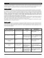
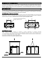
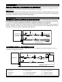
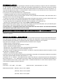
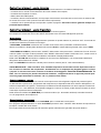
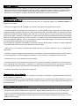
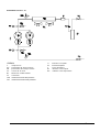
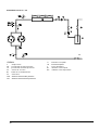
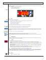
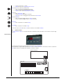
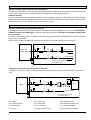
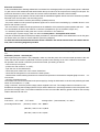
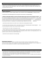
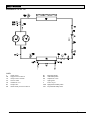
installation, operation and maintenance manual
Refrigeratori d’acqua con condensazione ad aria, pompe
di calore e motocondensanti - air cooled water chillers,
heat pumps and condensing units
IC_PERF H-MCH_MANUAL_A4
1
31-05-2007, 11:09
Performo R H CR CH MCR MCH
manuale di installazione, uso e manutenzione
MANUALE TECNICO
norme di sicurezza
installazione
uso e manutenzione
AVVERTENZE GENERALI
Il presente manuale fa parte, assieme allo schema elettrico, al manuale del microprocessore e agli allegati specifici per modello, della documentazione fornita a corredo della
macchina. Il tutto deve essere conservato con cura e messo a disposizione dell'operatore per ogni ulteriore consultazione.
Tutti gli interventi di manutenzione ordinaria e straordinaria devono essere eseguiti, nel
rispetto delle norme di sicurezza, da personale abilitato.
s e r i e : P E R F O R M O R - H - C R - C H - M C R-MCH
cod. : MTPE00
rev. : I-06-07
SOMMARIO
SICUREZZA
pag. 3
RICEVIMENTO E IMMAGAZZINAGGIO
pag. 4
MOVIMENTAZIONE
pag. 4
POSIZIONAMENTO
pag. 5
INSTALLAZIONE : collegamenti idraulici
pag. 5
INSTALLAZIONE : collegamenti elettrici
pag. 6
PRIMO AVVIAMENTO - funzionamento
pag. 6
SOSTA INVERNALE
pag. 8
MANUTENZIONE : ordinaria e straordinaria
pag. 8
SMANTELLAMENTO UNITA'
pag. 8
SCHEMI FRIGORIFERI
pag. 9
SCHEMI KIT IDRICO
pag. 17
MICROCONTROLLORE ECH 200
pag. 18
ALLARMI ECH 200
pag. 21
MICROCONTROLLORE Energy 400
pag. 22
ALLARMI Energy 400
pag. 25
2
S I C U R E Z ZA
La macchina è stata progettata in modo da ridurre al minimo i rischi per la sicurezza delle persone che con essa
andranno ad interagire. In sede di progetto non é stato tecnicamente possibile eliminare completamente le cause
di rischio. Pertanto è assolutamente necessario fare riferimento alle prescrizioni di seguito riportate.
Ac c es s o a l l ' u n i t à
L'accesso all'unità una volta che è stata installata, deve essere consentito solamente a operatori e tecnici abilitati.
Per operatore si intende una persona autorizzata dal proprietario della macchina a compiere operazioni sulla stessa (in accordo con quanto riportato nel presente manuale). Per tecnico si intende una persona autorizzata dalla
VENCO o in subordine sotto la sua completa responsabilità da un distributore VENCO, a compiere operazioni sulla
macchina. Per proprietario della macchina si intende il legale rappresentante della società, ente o persona fisica
proprietaria dell'impianto in cui è installata la macchina VENCO. Egli é responsabile del rispetto di tutte le norme di
sicurezza indicate dal presente manuale e dalla normativa vigente.
Qualora per la natura del luogo di installazione non possa essere impedito l'accesso alla macchina da parte di
estranei, deve essere prevista una zona recintata attorno alla macchina ad almeno 1,5 metri di distanza dalle superfici esterne, all'interno della quale possono operare solo operatori e tecnici.
Gli operatori o tecnici devono operare sulla macchina con un opportuno abbigliamento antinfortunistico (scarpe,
guanti, elmetti ecc.) e con opportun i utens i l i .
R i s c h i r es i du i
L'installazione, l'avviamento, lo spegnimento, la manutenzione della macchina devono essere tassativamente eseguiti in accordo con quanto riportato nella documentazione tecnica del prodotto e comunque in modo che non venga generata alcuna situazione di rischio. I rischi che non é stato possibile eliminare in fase di progettazione sono riportati nella tabella seguente.
parte considerata
rischio residuo
modalità
batteria di scambio termico
piccole ferite da taglio
contatto
griglia ventilatore e ventilatore lesioni
interno unità :
compressore e tubo di
mandata
interno unità :
parti metalliche e cavi
elettrici
esterno unità :
zona circostante unità
ustioni
intossicazioni, folgorazione, ustioni gravi
intossicazioni, ustioni
gravi
precauzioni
evitare il contatto, usare
guanti protettivi
inserimento di oggetti non infilare oggetti di alcun tiappuntiti attraverso la po dentro la griglia dei ventilagriglia mentre il ventila- tori e non appoggiare oggetti
tore sta funzionando
sopra le griglie
contatto
evitare il contatto, usare
guanti protettivi
difetto di isolamento cavi
alimentazione a monte
del quadro elettrico
dell'unità; parti metalliche in tensione
protezione eletttrica adeguata
della linea alimentazione;
massima cura nel fare il collegamento a terra delle parti metalliche
incendio a causa corto
circuito o surriscaldamento della linea alimentazione a monte del
quadro el.dell'unità
sezione dei cavi e sistema di
protezione della linea alimentazione elettrica conformi alle
norme vigenti
3
R I C E V I M E N TO E I M M AGA Z Z I N A GGI O
Controllare, all'atto del ricevimento, che il materiale non abbia subito danni e che corrisponda a quanto indicato nel
documento di accompagnamento. Eventuali danni, o situazioni di consegna incompleta, devono essere tempestivamente segnalati. Il gruppo potrà essere immagazzinato in locali protetti dagli agenti atmosferici con temperature
da -20°C a massimo +55°C.
M OV I M E N TA Z I O N E
Le unità possono essere movimentate sia con carrelli elevatori che con gru. Bisogna prestare particolare attenzione a non danneggiare, durante la movimentazione, la batteria di condensazione. Fare riferimento ai pesi riportati
negli allegati. Si consiglia la movimentazione della macchina imballata.
S o l l ev a m en t o co n c a r r el l o el ev a t o r e
Se si usa un carrello elevatore, assicurarsi prima di ogni cosa che sia di portata adeguata e che le forche siano
lunghe almeno 1200 mm. L'unità deve essere sollevata posizionando le forche del carrello secondo le indicazioni
riportate nella figura seguente. Assicurarsi che l'unità sia in perfetto equilibrio stabile.
1000
Le forche del carrello elevatore devono
sporgere di almeno 50 mm
1300
PER
FOR
Perfo
rmMO
o 4570-1
-10060
PER
PeFOR
rformMO
o 2121-5
-385
S o l l e v a m e n to co n g r u
Deve essere effettuato secondo lo schema in basso seguendo le istruzioni riportate.
Usare: un bilancino o delle barre divaricatrici, corde di adeguata portata (non catene), tubi di diametro 42 mm
(1" 1/4) che dovranno essere infilati nei fori predisposti nel basamento della macchina; bloccare le estremità dei tubi con spine e copiglie evitando che le corde si sfilino.
Assicurarsi che l'unità sia in perfetto equilibrio stabile.
spina
tubo O 42 mm
4
spina
P O S I Z I O N A M E N TO
S p a z i o d i r i s p et to p er i l f u n z i o n a m en to e l a m a n u t en z i o n e
L' unità deve essere installata rispettando gli spazi tecnici riportati negli allegati. Il piano su cui poggia l'unità deve
essere livellato e robusto adatto a sopportarne il peso durante il funzionamento.
An t i v i b r a n t i
Al fine di evitare trasmissione di vibrazioni alla struttura portante è opportuno installare negli appositi fori ricavati
nel basamento dell'unità dei supporti antivibranti (in gomma, forniti come accessorio opzionale). Il montaggio degli
antivibranti è evidenziato nello schema riportato negli allegati.
I N S TAL LA Z I ON E
Co l l eg a m en t i i d r a u l i c i : u n i t à c o n k i t i d r i c o i n c o r p o r a to
Si consiglia di effettuare il collegamento idrico del refrigeratore in accordo con lo schema seguente. In particolare è
assolutamente necessario installare sulla tubazione di ingresso un filtro contro le eventuali impurità contenute nell'acqua. La mancata installazione di detto filtro comporta il decadimento della garanzia.
Il
kit idrico incorporato é formato da: pompa di circolazione, serbatoio di accumulo,valvole sfiato aria, pressostato differenziale, valvola di sicurezza (solo su pompa di calore). Le tubazioni dovranno essere adeguatamente isolate e
sostenute in modo da non gravare sugli attacchi della macchina.
RC
M
T
GA
FA
Refrigeratore
con kit idrico
incorporato
M
F
VS
VS
VI
INGRES SO A CQU A
VI
U S C I T A A CQU A
T
GA
D I S POS I T IVI D A INS TALLA RE A C UR A
DELL' INS TA LLA TORE.
RS
Co l l eg a m en t i i d r a u l i c i : u n i t à s en z a k i t i d r i c o
Oltre a quanto detto sopra é necessario installare una pompa, un serbatoio di accumulo coibentato, un vaso di
espansione (vedi figura sottostante).
VS
RC
M
F
VS
P
T
FA
GA
SE
VI
VI
SA
Refrigeratore
M
VS
INGRES SO A CQUA
T
GA
VI
U SC I TA A CQU A
D I S POS I T IVI DA INSTA LLA RE A C UR A
DELL' INST ALLA TORE.
RS
M = manometro
RC = rubinetto di carico
RS = rubinetto di scarico
VS = sfiato aria
FA = filtro acqua
GA = giunto antivibrante
T = termometro
VI = valvola intercettazione
F
P = pompa
SE = vaso espansione
SA = serbatoio accumulo
= flussostato esterno
5
C o l l eg a m e n t i e l e t t r i c i
Nei disegni dimensionali riportati negli allegati é indicata la posizione prevista per l'ingresso dei cavi di alimentazione. Per accedere al quadro elettrico e quindi alla morsettiera di alimentazione é necessario smontare il pannello
frontale superiore. Per il dimensionamento della linea di alimentazione fare riferimento ai valori di potenza e corrente riportati negli schemi elettrici. Lo schema elettrico della macchina si trova all'interno del vano compressori assieme al resto della documentazione a corredo.
E' necessario porre particolare attenzione ai seguenti punti:
- i collegamenti elettrici devono essere eseguiti da personale qualificato;
- i cavi di alimentazione devono essere protetti a monte contro gli effetti del cortocircuito e del sovraccarico da un
dispositivo idoneo conforme alle leggi vigenti;
- la sezione dei cavi deve essere commisurata alla taratura del sistema di protezione a monte e deve tenere conto
di tutti i fattori che la possono influenzare (temperatura, tipo di isolante, lunghezza, ecc.);
- è molto importante che il collegamento alla rete di terra sia effettuato con la massima cura.
- verificare il tipo di alimentazione che puo' essere trifase o trifase con neutro.
Nella morsettiera del quadro elettrico sono previsti due coppie di morsetti (contatti puliti): una é per l'allarme generale a distanza, l'altra é per l'ON/OFF remoto (vedi schema elettrico).
In particolare per i collegamenti delle unità motocondensanti alle unità interne e al termostato ambiente,
fare riferimento agli schemi elettrici forniti a corredo.
P R I M O AVV I A M E N TO O AVV I A M E N TO DO P O U N A L U N GA S OS TA - F U N Z I O N A M E N TO
Prima di procedere all'avviamento del refrigeratore é necessario effettuare controlli preliminari della parte elettrica,
idraulica e frigorifera.
Co n t r o l l i p r el i m i n a r i - p a r t e el et t r i c a
Prima di effettuare i controlli di cui al presente paragrafo è necessario assicurarsi che la linea di alimentazione elettrica dell'unità sia sezionata a monte della stessa. Assicurarsi che il dispositivo di sezionamento sia lucchettato o
che sulla maniglia di azionamento sia applicato l'apposito cartello di avvertimento a non operare.
Ogni intervento va eseguito in mancanza di tensione procedendo come di seguito:
- togliere pannello frontale superiore;
- portare l'interruttore generale nella posizione "0" (OFF);
- aprire lo sportello del quadro elettrico;
- verificare che i cavi di alimentazione siano opportunamente dimensionati;
- verificare che il refrigeratore sia connesso all'impianto di terra;
- verificare il corretto serraggio delle viti che fissano i conduttori ai componenti elettrici presenti nel quadro in modo
da garantire un adeguato contatto;
- chiudere lo sportello del quadro elettrico.
A questo punto si può dare tensione alla macchina chiudendo il dispositivo di sezionamento della linea e portando
l'interruttore generale della macchina nella posizione "1" (ON).
Controllare, con un voltmetro, i valori della tensione di fase fornti all'unità. Il valore della tensione di alimentazione
deve essere 400 V +/- 10 %. Determinare la tensione media di fase (RS+ST+RT)/3 e la differenza percentuale fra
ciascuna delle tensioni di fase e questo valore medio. La differenza massima non deve essere superiore al 3 %.
Una variazione maggiore annulla la garanzia.
ESEMPIO:
R-S= 397V ; S-T= 406V ; R-T= 395V
media dei valori : (397+406+395) / 3 = 399,3
differenza percentuale : (406-397) / 399,3 x 100 = 2,25 %
(406-395) / 399,3 x 100 = 2,75 %
(397-395) / 399,3 x 100 = 0,5 %
6
Co n t r o l l i p r el i m i n a r i - p a r t e i d r a u l i c a
- controllare il corretto collegamento fra gli attacchi idrici della macchina e le tubazioni dell'impianto;
- controllare che le valvole di intercettazione del circuito idraulico siano aperte;
- controllare che l'impianto sia carico;
- sfiatare tutta l'aria dall'impianto;
- controllare, durante il funzionamento, che la pompa di circolazione sia funzionante e che il senso di rotazione della stessa sia in senso orario (vista di fronte alla calotta copriventola);
- controllare che la portata d'acqua corrisponda a quella di progetto: assicurarsi che sia garantita sempre una
portata d'acqua costante.
Co n t r o l l i p r el i m i n a r i - p a r t e f r i go r i f er a
Controllare visivamente l'integrità dei vari componenti del circuito frigorifero.
Sui compressori assicurarsi che il livello dell'olio lubrificante sia a circa metà dell'apposito spioncino.
Av v i a m e n to
Posizionare l'interruttore generale magnetotermico presente sul quadro elettrico in posizione "ON". A seconda del
modello della macchina procedere come segue:
- PERFORMO R-CR-MCR: assicurarsi che i contatti on/off remoto siano ponticellati; verificare assenza
allarme controllando il display della tastiera nelle versioni R-CR e contatti allarme generale nelle versioni MCR.
- PERFORMO H-CH-MCH: premere tasto "ON/OFF" della tastiera microprocessore e selezionare il modo di funzionamento (chiller o pompa di calore) tramite il tasto "MODE" della stessa tastiera; assicurarsi che i contatti on/off remoto siano ponticellati; verificare assenza allarme controllando il display della tastiera.
Nelle unità R-H-CR-CH l'avviame nto è ritardato di circa tre minuti dall'istante in cui la temperatura dell'acqua
all'ingresso della macchina lo richiede.
Nelle unità MCR-MCH l'avviamento è diretto previo consenso esterno (220 V : vedi schema elettrico).
NOTA IMPORTANTE : nelle unità dove sono installati compressori scroll trifasi è molto importante controllare il senso di rotazione dei compressori. Se alimentati con la sequenza fasi sbagliata girano in senso
contrario. In tal caso sono molto rumorosi e rischiano di danneggiarsi: invertire immediatamente le
fasi. Per un controllo piu' preciso del senso di rotazione , collegare attraverso le apposite prese di pressione un gruppo manometri e verificare che le pressioni siano esatte.
F u n z i o n a m en to a r eg i m e
Nelle unità R-H-CR-CH Il sistema di controllo a microprocessore del refrigeratore regolerà la potenza frigorifera della macchina (accensione, spegnimento del compressore) in dipendenza del carico termico dell'impianto; controllare le temperature di ingresso e uscita acqua: la differenza tra tali temperature non deve superare il limite massimo di circa 7°C. Una differenza di temperatura maggiore è sintomo di scarsa portata d'acqua (rispetto al valore
nominale)o di presenza di aria nell'impianto.
Nelle unità motocondensanti (MCR-MCH) un consenso esterno (es. termostato ambiente) comanda l'accensione e lo spegnimento del compressore.
S p eg n i m en to e a c c en s i o n e
Per spegnere temporaneamente le unità: R-CR-MCR aprire i contatti dell' on/off remoto.
Per spegnere temporaneamente le unità: H-CH-MCH premere il tasto "ON/OFF" della tastiera microprocessore
e/o aprire i contatti dell' on/off remoto.
Per lunghi periodi di fermata sezionare la macchina agendo sull'interruttore generale del quadro elettrico.
7
S O S TA I N V E R N A L E
Se l'impianto idraulico è stato caricato con acqua è necessario provvedere alla sua evacuazione a fine stagione
estiva per evitare la formazione di ghiaccio durante l'inverno. Se l'impianto è stato caricato con soluzione antigelo
l'operazione non deve essere effettuata. Prima dell'inizio della stagione fredda è necessario verificare con un
densimetro la concentrazione di glicole della miscela, rabboccando il circuito se necessario.
M AN U T E N Z I ON E
M a n u t en z i o n e o r d i n a r i a
La manutenzione ordinaria consiste in semplici operazioni che si consiglia di eseguire con cadenza mensile procedendo come segue:
- verificare il serraggio delle viti di fissaggio dei ventilatori alla griglia e della griglia sulla struttura;
- verificare le batterie di condensazione. Per garantire un corretto scambio termico, queste devono essere pulite. E'
necessario quindi provvedere alla rimozione della eventuale sporcizia accumulatasi sulla loro superficie per effetto
dell'azione di trasporto dell'aria. Togliere carte, foglie ecc. e pulire le alette con un getto d'aria. Per evitare danneggiamenti alle alette in alluminio é necessario che il getto d'aria sia diretto perpendicolarmente alla superficie della
batteria. L'operazione di pulizia deve essere condotta con estrema cura poichè l'alettatura delle batterie è facilmente danneggiabile (alluminio da 0,12 mm).Qualora le alette risultino danneggiate, é necessario provvedere alla
loro sistemazione pettinandole con un apposito attrezzo.
Prima di effettuare operazioni sulle batterie è necessario indossare guanti protettivi in quanto il contatto accidentale
con le alette della stessa può provocare delle piccole ferite da taglio;
- verificare che il cavo elettrico di alimentazione della macchina non presenti alterazioni che ne compromettano
l'isolamento;
- verificare il corretto serraggio delle viti che fissano i conduttori ai componenti elettrici presenti nel quadro elettrico
in modo da garantire un corretto collegamento elettrico; lo stesso dicasi per i collegamenti di messa a terra.
- controllare che non ci siano perdite nel circuito idraulico;
- controllare, durante il funzionamento dei compressori le pressioni di mandata e aspirazione. E' necessario rimuovere i pannelli del vano compressori e collegarsi con i manometri sulle opportune prese di pressione predisposte
nei circuiti frigoriferi. Questa operazione deve necessariamente essere effettuata da personale abilitato.
- controllare visivamente la spia livello olio compressori.
M a n u t en z i o n e s t r ao r d i n a r i a
La manutenzione straordinaria consiste in operazioni che si rendono necessarie a seguito di anomalie di funzionamento. Rientrano in questi casi:
lo scarico del refrigerante, la carica di refrigerante, il rabbocco d'olio, la sostituzione del filtro deidratore, la messa
in vuoto dei circuiti, la configurazione del controllo. Queste operazioni devono essere eseguite tassativamente da
personale abilitato.
S M A N T E L L A M E N TO D E L L ' U N I T A '
La macchina è stata progettata e costruita per garantire un funzionamento continuativo. La durata di alcuni componenti principali, quali il ventilatore ed il compressore, dipende dalla manutenzione a cui sono stati sottoposti.
In caso di smantellamento dell'unità, l'operazione dovrà essere eseguita da personale frigorista specializzato.
Il fluido frigorigeno e l'olio lubrificante contenuti nel circuito dovranno essere recuperati, in accordo con le norme
vigenti nel Vostro Paese.
8
S C H E M I F R I GO R I F E R I
PERFORMO R- CR 21 - 90
B1
B2
LEGENDA
C
HP
LP
VC
CO
EV
PD
comp r es so r e
p r es sostato d i al ta p r es s i one
p r es sostato d i bas sa p r es s i one
v al vo l e d i se r v i zio
batte r i a d i condens azione
e vapo r ato r e
p r e ssostato di f fe r en zi al e ( l ato acqua)
B1
B2
VE
LI
F
VSH
VSL
sonda ingresso liquido evaporatore
sonda uscita liquido evaporatore
v al vo l a di espans i one
Ind i cato r e d i l iqu ido
f i l tr o de id r ato r e
valvola di sicurezza alta pressione
valvola di sicurezza bassa pressione
9
PERFORMO R- CR 110 - 250
LEGENDA
C
HP
LP
VC
CO
EV
PD
comp r es so r e
p r es sostato d i al ta p r es s i one
p r es sostato d i bas sa p r es s i one
v al vo l e d i se r v i zio
batte r i a d i condens azione
e vapo r ato r e
p r e ssostato di f fe r en zi al e ( l ato acqua)
10
B1
B2
VE
LI
F
VSH
VSL
sonda ingresso liquido evaporatore
sonda uscita liquido evaporatore
v al vo l a di espans i one
Ind i cato r e di l iqu ido
f i l tr o de id r ato r e
valvola di sicurezza alta pressione
valvola di sicurezza bassa pressione
PERFORMO H- CH 21 - 40
LEGENDA
C
HP
LP
VC
CO
EV
PD
VQ
NR
comp r es so r e
p r es sostato d i al ta p r es s i one
p r es sostato d i bas sa p r es s i one
v al vo l e d i se r v i zio
batte r i a d i condens azione
e vapo r ato r e
p r e ssostato di f fe r en zi al e ( l ato acqua)
v al vo l a a qu attr o v i e
v al vo l a di non r i to r no
B5
B6
VE
LI
F
VSH
VSL
LR
sonda ingresso liquido evaporatore
sonda uscita liquido evaporatore
v al vo l a di espans i one
Ind i cato r e di l iqu ido
f i l tr o de id r ato r e
valvola di sicurezza alta pressione
valvola di sicurezza bassa pressione
ricevitore di liquido
11
PERFORMO H- CH 45 - 80
LEGENDA
C
HP
LP
VC
CO
EV
PD
VQ
NR
comp r es so r e
p r e ssostato d i al ta p r es s i one
p r e ssostato d i bas sa p r es s i one
v al vo l e d i se r v i zio
batte r i a di condens azione
e vapo r ato r e
p r essostato di f fe r en zi al e ( l ato acqua)
v al vo l a a qu attr o v i e
v al vo l a di non r i to r no
12
B5
B6
VE
LI
F
VSH
VSL
LR
sonda ingresso liquido evaporatore
sonda uscita liquido evaporatore
v al vo l a di espans i one
Ind i cato r e di l iqu ido
f i l tr o de id r ato r e
valvola di sicurezza alta pressione
valvola di sicurezza bassa pressione
ricevitore di liquido
PERFORMO H- CH 110 - 250
LEGENDA
C
HP
LP
VC
CO
EV
PD
VQ
NR
comp r es so r e
p r es sostato d i al ta p r es s i one
p r es sostato d i bas sa p r es s i one
v al vo l e d i se r v i zio
batte r i a d i condens azione
e vapo r ato r e
p r e ssostato di f fe r en zi al e ( l ato acqua)
v al vo l a a qu attr o v i e
v al vo l a di non r i to r no
B5
B6
VE
LI
F
VSH
VSL
LR
sonda ingresso liquido evaporatore
sonda uscita liquido evaporatore
v al vo l a di espans i one
Ind i cato r e di l iqu ido
f i l tr o de id r ato r e
valvola di sicurezza alta pressione
valvola di sicurezza bassa pressione
ricevitore di liquido
13
PERFORMO MCR 21 - 40
LEGENDA
C
PA
PB
VC
BC
VL
VSH
VSL
comp r es so r e
p r es sostato d i al ta p r es s i one
p r es sostato d i bas sa p r ess i one
v al vo l e d i se r v i zio
batte r i a d i condens azione
v ent i l ato r i
valvola di sicurezza alta pressione
valvola di sicurezza bassa pressione
14
LI
LR
F
RL
RA
Ind i cato r e di l iqu i do
ricevitore di liquido
f i l tr o de i d r ato r e
r ubi netto l i nea l i qu i do
r ubi netto l i nea asp i r azi one
PERFORMO MCR 45 - 90
LEGENDA
C
PA
PB
VC
BC
VL
VSH
VSL
comp r es so r e
p r es sostato d i al ta p r es s i one
p r es sostato d i bas sa p r es s i one
v al vo l e d i se r v i zio
batte r i a d i condens azione
v ent i l ato r i
valvola di sicurezza alta pressione
valvola di sicurezza bassa pressione
LI
LR
F
RL
RA
Ind i cato r e di l iqu ido
ricevitore di liquido
f i l tr o de id r ato r e
r ubi netto l i nea l i qu i do
r ubi netto l i nea aspi r azi one
15
PERFORMO MCR 110 - 250
LA
LEGENDA
C
HP
LP
VC
BC
VL
VSH
VSL
16
comp r es so r e
p r es sostato d i al ta p r es s i one
p r es sostato d i bas sa p r ess i one
v al vo l e d i se r v i zio
batte r i a d i condens azione
v ent i l ato r i
valvola di sicurezza alta pressione
valvola di sicurezza bassa pressione
LI
LR
F
RL
RA
Ind i cato r e di l iqu ido
ricevitore di liquido
f i l tr o de id r ato r e
r ubi netto l i nea l i qu i do
r ubi netto l i nea aspi r azi one
S C H E M I K I T I D R I CO
C I RCU I TO DEL K I T I D R I CO ( opt iona l ) CON SE R BATOIO D I ACCU M ULO
VS
VA
ingresso acqua
P
VI
SB
FA
RS
EV
PD
SE
uscita acqua
valido
÷ 250);
210 0
÷ )34)
va l i doper
peunità
r un iPerformo
tà Pe r fo rR
m-oHR (taglie
/CR / H21
/CH
( 2 1 ÷CR
3 8 -) CH
; R (taglie
( 45 ÷ 1
;
C I RCU I TO DEL K I T I D R I CO (opt iona l ) SENZA SE R BATOIO D I ACCU M ULO
ingresso acqua
ingresso acqua
VA
VS
P
PD
VA
P
VS
uscita acqua
FA
SE
FA
PD
PD
EV
EV
EV
SE
uscita acqua
solo per unità 110÷160
valido
- CR
- CH
va l i doper
peunità
r un iPerformo
tà Pe r fo rRm-oHCR
( 45
÷ 1 0(taglie
0 ) ; C40
H÷
( 4250)
5÷90÷1
LEGENDA
FA
VA
VS
PD
f i l tr o acqua (opti on al )
v al vo l a d i s i cu r ezza (3 b ar )
v al v ol a d i s f i ato ar i a
p r es sostato di f f e r . ( l ato acqua)
RS
SE
SB
v al vol a d i sc ar i co acqua
v aso d i espans i one
se r bato i o accumu l o
VI
P
EV
v al vo l a a s f e r a
pompa
e vapo r ato r e
17
MICROCONTROLLORE
6
INTERFACCIA UTENTE
L’interfaccia, costituita dal frontale dello strumento, permette di svolgere tutte le operazioni legate all’uso dello strumento
ed in particolare di:
Impostare il modo di funzionamento
•
Gestire le situazioni di allarme
•
Verificare lo stato delle risorse
•
Tastiera
6.1
mode
Tasti
Seleziona il modo di funzionamento:
•
se è abilitata la modalità heat ad ogni pressione del tasto si ha la seguente sequenza
stand-by ! cooling ! heating ! stand-by
•
se la modalità heat non è abilitata:
stand-by ! cooling ! stand-by
IMG INFO
Nella modalità menu diventa il tasto SCROLL UP o UP valore (incremento del valore).
on-off – reset
allarmi
Attua il reset degli allarmi, nonché l’accensione e lo spegnimento dello strumento.
Una pressione singola resetta tutti gli allarmi a riarmo manuale non attivi;
Tenendo premuto il tasto per 2 secondi lo strumento passa da on (acceso) a off (spento) o da off a on. In off rimane
acceso solo il punto decimale del display Nella modalità menu diventa il tasto SCROLL DOWN o DOWN valore decremento
del valore)
IMG INFO
Combinazione
mode e on-off
: set
Tasti “mode” e “on-off” premuti contemporaneamente.
Premendo e rilasciando entrambi i tasti entro 2 secondi si scende di un livello nel menu di visualizzazione.
Tenendo premuto entrambi i tasti per più di 2 secondi si sale di un livello.
Se si sta visualizzando l’ultimo livello di un menu la pressione e il rilascio entro due secondi fa salire in ogni caso di un
livello.
6.2
Visualizzazioni
Il dispositivo è in grado di comunicare qualsiasi tipo di informazione inerente il suo status, la sua configurazione, gli allarmi
attraverso un display e dei led presenti nel frontale.
6.2.1
<IMG INFO>
Display
In visualizzazione normale vengono rappresentati:
la temperatura di regolazione, in decimi di gradi celsius con punto decimale o farenaith senza punto decimale
•
il codice di allarme se almeno uno è attivo. Nel caso di più allarmi attivi viene visualizzato il primo secondo la Tabella
•
Allarmi.
Se la termoregolazione non è basata su ingressi analogici e dipende dallo stato di un ingresso digitale (AI1 o AI2
•
configurati come ingressi digitali) viene visualizzata la label “On” o “Off” in funzione dello stato del termoregolatore
(attivo - non attivo).
Nella modalità menu la visualizzazione è funzione della posizione in cui ci si trova. Per aiutare l’utilizzatore ad
•
identificare la funzione impostata sono utilizzate delle label (etichette) e dei codici.
Punto decimale: nella visualizzazione delle ore di funzionamento indica che il valore deve essere moltiplicato x 100
•
6.2.2
Visualizzazione SET per macchine aria-aria (solo per modelli Ech 2xxB)
Per facilitare l’interfaccia utente nelle versioni aria-aria, ponendo il parametro Pa H53 = 1 viene visualizzato normalmente il
set relativo alla modalità selezionata; una pressione dei tasti UP e DOWN, della tastiera remota, modifica direttamente il
set della modalità impostata. Nella tastiera locale non è possibile modificare direttamente il set.
6.2.3
Led
Led compressore 1.
ON se il compressore 1 è attivo
•
18
•
•
OFF se il compressore 1 spento
BLINK se sono in corso temporizzazioni di sicurezza
Led compressore 2 (o stadio di parzializzazione)
ON se il compressore (parzializzazione) è attivo
•
OFF se il compressore (parzializzazione) è spento
•
BLINK se sono in corso temporizzazioni di sicurezza
•
Led defrost
ON se sbrinamento attivo
•
OFF se sbrinamento disabilitato o terminato
•
BLINK se è in corso il conteggio del tempo (intervallo di sbrinamento)
•
Led resistenza/boiler
ON se la resistenza antigelo interna o il boiler sono attivi
•
OFF se la resistenza antigelo interna o il boiler sono spenti
•
Led heating
ON se il dispositivo è in modalità heating.
•
<IMG INFO>
Led cooling
ON se controllore in modalità cooling
•
IMG INFO
Se non sono accesi né il led HEAT né il led COOL il controllore è in modalità STAND-BY
6.3
Tastiera remota
La tastiera remota a display è una copia fedele della visualizzazione delle informazioni sullo strumento e dispone degli
stessi led.
Tastiera Remota
<IMG INFO>
Le funzionalità sono identiche a quelle elencate nella sezione tasti e visualizzazioni.
L’unica differenza è rappresentata dall’utilizzo dei tasti UP e DOWN (incremento e decremento del valore) separati dai
tasti MODE e ON/OFF. Il collegamento al dispositivo è illustrato di seguito:
REMOTE KEYBOARD
24 25 26
REAR VIEW
SERIAL
KEYB
CONN B
EXP
CONN A
<IMG INFO>
19
20
Sonda regolazione
Allarme attivo
Livello 0
Valore parametro
Valore parametro
Valore parametro
Valore parametro
Valore parametro
Valore parametro
Valore parametro
Indice parametro H01...
Indice parametro C01...
Indice parametro F01...
Indice parametro A01...
Indice parametro P01...
Indice parametro r01...
Indice parametro d01...
Codice ingresso 01...05
Parametro configurazione CnF
Parametro compressore CP
Parametro ventilazione FAn
Parametro allarmi ALL
Parametro pompa PUP
Parametro antigelo Fro
Parametro sbrinamento dFr
Ingressi digitali Id
Parametri PAr
Numero ore parameto
Numero ore parameto
Numero ore parameto
Valore password
Ore compressore 1 OH1
Ore compressore 2 OH2
Ore pompe OPH
Password Pss
Ore funzioamento OHr
Stato ingresso digitale
Codice allarmi attivi E00
Allarmi Err
Valore ingresso analogico
Valore set heating
Label set heating HEA
Livello 4
Codice ingresso t01...t04
Valore set cooling
Livello 3
Label set cooling Coo
Livello 2
Ingressi analogici TP
Set point SEt
Livello 1
La struttura è organizzata come descritto nel seguente schema:
STRUTTURA DEL MENU'
ALLARMI
Se durante il normale funzionamento della macchina interviene qualche anomalia, il
controllore ferma la macchina e segnala all'utente il codice di allarme relativo alla
sicurezza intervenuta. Dopo aver verificato l'allarme ed eliminata la causa, si potrà
procedere al ripristino del controllore premendo il tasto on/off.
Ripristino degli allarmi
Con una rotazione ciclica, il significato che assume la pressione on/off. Così come
descritto in precedenza il tasto svolge due funzioni distinte; se premuto per 1
secondo funge da "ripristino allarme", se premuto per 2 secondi funge da
"accensione-spegnimento controllore".
In presenza di un'anomalia il controllore segnala all'utente, attraverso il display
lampeggiante, il codice dell'allarme attivo.
Per ripristinare il controllore e riprendere il normale funzionamento dell'unità, premere
per 1 secondo il tasto on/off.
Codice degli allarmi
Nello schema seguente sono rappresentati il codice di allarme. Alcuni codici di allarme
sono cumulativi, hanno cioè più significati. Tutti gli altri allarmi hanno un solo
siginificato. Una particolare attenzione si deve prestare al presentarsi del codice E00
ini quanto questo non è un allarme di mal funzionamento della macchina ma segnala
che è stato azionato l'interruttore di on/off remoto oppure lo spegnimento dell'unità
comandato dall'orologio programmatore (optional).
E00: stand-by unità tramite comando remoto
E01: intervento del pressostato di alta pressione
E01: intervento della protezione termica interna del compressore
E01: intervento sonda di temperatura tubo di mandata compressore (se presente)
E02: intervento del pressostato di bassa pressione
E04: intervento protezione termica ventilatore/i
E05: intervento procedura di sicurezza antigelo
E06: sonda di temperatura guasta uscita acqua scambiatore
E07: sonda di controllo condensazione-evaporazione guasta
E40: sonda di temperatura guasta ingresso acqua scambiatore
E41: intervento termico pompa acqua (se presente)
E41: intervento presssostato differenziale acqua
21
MICROCONTROLLORE
5
INTERFACCIA UTENTE
L’interfaccia, costituita dal frontale dello strumento, permette di svolgere tutte le operazioni legate all’uso dello strumento
ed in particolare di:
Impostare il modo di funzionamento
•
Gestire le situazioni di allarme
•
Verificare lo stato delle risorse
•
x
Frontale dello strumento
Tastiera
Lo strumento può funzionare senza l’ausilio di alcuna tastiera
<IMG INFO>
36,75
5.1
Mode
<IMG INFO>
Tasti
Seleziona il modo di funzionamento:
se è abilitata la modalità heat ad ogni pressione del tasto si ha la seguente sequenza
Stand-by -!
! cooling ! heating ! stand-by
se la modalità heat non è abilitata:
Stand-by ! cooling ! stand-by
Nella modalità menù diventa il tasto SCROLL UP o UP valore (incremento del valore).
On-off – Reset
allarmi
Attua il reset degli allarmi, nonché l’accensione e lo spegnimento dello strumento.
Una pressione singola resetta tutti gli allarmi a riarmo manuale non attivi; vengono resettati anche tutti i contatori del
numero di interventi ora anche se gli allarmi non sono attivi.
Tenendo premuto il tasto per 2 secondi lo strumento passa da on (acceso) a off (spento) o da off a on. In off rimane
acceso solo il punto decimale del display Nella modalità menù diventa il tasto SCROLL DOWN o DOWN valore decremento
del valore)
Combinazione
mode – onoff
Tasti “mode” e “on-off” premuti contemporaneamente.
Premendo e rilasciando entrambi i tasti entro 2 secondi si scende di un livello nel menù di visualizzazione.
Tenendo premuto entrambi i tasti per più di 2 secondi si sale di un livello.
Se si sta visualizzando l’ultimo livello di un menù la pressione e il rilascio entro due secondi fa salire in ogni caso di un
livello.
<IMG INFO>
5.2
Visualizzazioni
Il dispositivo è in grado di comunicare qualsiasi tipo di informazione inerente il suo status, la sua configurazione, gli allarmi
attraverso un display e dei led presenti nel frontale.
5.2.1
IMG INFO
Display
In visualizzazione normale vengono rappresentati:
la temperatura di regolazione, in decimi di gradi celsius o fahrenheit
•
il codice di allarme se almeno uno è attivo. Nel caso di più allarmi attivi viene visualizzato il primo secondo la Tabella
•
Allarmi.
Se la termoregolazione non è analogica e dipende dallo stato di un ingresso digitale (ST1 o ST2 configurati come
•
ingressi digitali) viene visualizzata la label “On” o “Off” in funzione dello stato del termoregolatore (attivo - non
attivo).
Nella modalità menù la visualizzazione è funzione della posizione in cui ci si trova. Per aiutare l’utilizzatore ad
•
identificare la funzione impostata sono utilizzate delle label (etichette) e dei codici.
5.2.2
Led
Led 1 compressore 1.
ON se il compressore 1 è attivo
OFF se il compressore 1 spento
•
BLINK veloce se sono in corso temporizzazioni di sicurezza
•
BLINK lento se il compressore è in sbrinamento
•
Led step 2 di potenza
ON se lo step 2 di potenza è attivo
22
•
•
•
OFF se lo step 2 di potenza non è attivo
BLINK veloce se sono in corso temporizzazioni di sicurezza
BLINK lento se step 2 in sbrinamento
Led step 3 di potenza
ON se lo step 3 di potenza è attivo
OFF se lo step 3 di potenza non è attivo
•
BLINK veloce se sono in corso temporizzazioni di sicurezza
•
BLINK lento se step 3 in sbrinamento
•
Led
•
•
•
•
step 4 di potenza
ON se lo step 4 di potenza è attivo
OFF se lo step 4 di potenza non è attivo
BLINK veloce se sono in corso temporizzazioni di sicurezza
BLINK lento se step4 in sbrinamento
Led resistenza/boiler
ON se la almeno una resistenza antigelo interna è attiva
•
OFF se sono entrambi spente
•
<IMG INFO>
Led heat
ON se il dispositivo è in modalità heating.
•
Led cool
ON se controllore in modalità cooling
•
Se non sono accesi né il led HEAT né il led COOL il controllore è in modalità STAND-BY
In off rimane acceso solo il punto decimale del display.
5.3
Tastiera Remota
Tastiera da parete
La tastiera remota a display è una copia fedele della visualizzazione delle informazioni sullo strumento e dispone degli
stessi led;
Tastiera Remota
Le funzionalità sono identiche a quelle elencate nella sezione visualizzazioni.
L’unica differenza è rappresentata dall’utilizzo dei tasti UP e DOWN (incremento e decremento del valore) separati dai
tasti MODE e ON/OFF
5.4
Programmazione parametri - Livelli dei menù
La modifica dei parametri del dispositivo può avvenire tramite Personal Computer (disponendo dell’apposito software e
della chiave d’interfaccia e cavi adeguati), o tramite tastiera;
In quest’ultimo caso l’accesso ai vari parametri è organizzato in sottolivelli a cui si può accedere premendo
contemporaneamente i tasti “mode ed “on-off” (vedi sopra).
Ogni livello di menù è identificato da un codice mnemonico visualizzato sul display.
La struttura è organizzata come descritto nel seguente schema:
23
24
Sonda regolazione
Allarme attivo
Livello 0
Indice par.
Indice par.
Indice par.
Indice par.
Indice par.
Indice par.
Par. compressore:
Par.i ventilazione:
Par. allarmi:
Par. pompa:
Par. antigelo:
Par. sbrinamento:
Par. espansione:
Ore. Funz.:
Ore Pompa:
Ore Comp:
Valore password
-
..
Indice par.
Par. configurazione:
Parametri:
Password:
..
Indice par.
Code ing.:
Ing. digitali:
Numero ore
Numero ore
..
..
..
..
..
..
Stato ing. digitale
Code All. Attivi:
Allarmi:
-
Val. ing. analogico
Code ing.:
Inp. Analog:
-
Valore set heating
Label Set heating:
Livello 3
Valore set cooling
Livello 2
Label Set cooling:
Set point:
Livello 1
Valore parametro
Valore parametro
Valore parametro
Valore parametro
Valore parametro
Valore parametro
Valore parametro
Valore parametro
Livello 4
STRUTTURA DEL MENU'
ALLARMI
Se durante il normale funzionamento della macchina interviene qualche anomalia, il
controllore ferma la macchina e segnala all'utente il codice di allarme relativo alla
sicurezza intervenuta. Dopo aver verificato l'allarme ed eliminata la causa, si potrà
procedere al ripristino del controllore premendo il tasto on/off.
Ripristino degli allarmi
Con una rotazione ciclica, il significato che assume la pressione on/off. Così come
descritto in precedenza il tasto svolge due funzioni distinte; se premuto per 1
secondo funge da "ripristino allarme", se premuto per 2 secondi funge da
"accensione-spegnimento controllore".
In presenza di un'anomalia il controllore segnala all'utente, attraverso il display
lampeggiante, il codice dell'allarme attivo.
Per ripristinare il controllore e riprendere il normale funzionamento dell'unità, premere
per 1 secondo il tasto on/off.
Codice degli allarmi
Nello schema seguente sono rappresentati il codice di allarme. Alcuni codici di allarme
sono cumulativi, hanno cioè più significati. Tutti gli altri allarmi hanno un solo
siginificato. Una particolare attenzione si deve prestare al presentarsi del codice E00
ini quanto questo non è un allarme di mal funzionamento della macchina ma segnala
che è stato azionato l'interruttore di on/off remoto oppure lo spegnimento dell'unità
comandato dall'orologio programmatore (optional).
E00:
E01:
E01:
E02:
E03:
E03:
E04:
E05:
E06:
E07:
E13:
E13:
E21:
E21:
E22:
E23:
E23:
E24:
E27:
E33:
E33:
E40:
E41:
E41:
stand-by unità tramite comando remoto
intervento del pressostato di massima circuito 1
intervento dispositivo di controllo sequenza e presenza fasi di alimentazione
intervento del pressostato di minima circuito 1
intervento della protezione termica interna del compressore 1
intervento termostato tubo di mandata compressore 1 (se presente)
intervento protezione termica ventilatori circuito 1
intervento procedura di sicurezza antigelo
sonda di temperatura guasta uscita acqua scambiatore
sonda di controllo condensazione-evaporazione guasta circuito 1
intervento della protezione termica interna del compressore 2
intervento termostato tubo di mandata compressore 2 (se presente)
intervento del pressostato di massima circuito 2
intervento dispositivo di controllo sequenza e presenza fasi di alimentazione
intervento del pressostato di minima circuito 2
intervento della protezione termica interna del compressore 3
intervento termostato tubo di mandata compressore 3 (se presente)
intervento protezione termica ventilatori circuito 2
sonda di controllo condensazione-evaporazione guasta circuito 2
intervento della protezione termica interna del compressore 4
intervento termostato tubo di mandata compressore 4 (se presente)
sonda di temperatura guasta ingresso acqua scambiatore
intervento termico pompa acqua
intervento presssostato differenziale acqua
25
TECHNICAL MANUAL
safety standars
installation
use and maintenance
GENERAL INSTRUCTIONS
Together with the wiring diagram, the microprocessor manual and the specific enclosures
for the model, this manual is a part of the documentation supplied with the machine. This
must be kept carefully and be available to the operator for future reference. All ordinary and
extraordinary maintenance must be carried out by authorised personnel in compliance with
the safety regulations.
series : PERFORMO R-H-CR-CH-MCR-MCH
cod. : MTPE00
rev. : E-06-07
INDEX
SAFETY
page 3
RECEPTION AND STORAGE
page 4
MOVEMENT
page 4
POSITIONING
page 5
INSTALLATION: hydraulic connections
page 5
INSTALLATION: electrical connections
page 6
INITIAL START-UP - OPERATION
page 6
WINTER STORAGE
page 8
MAINTENANCE: ordinary and extraordinary
page 8
DISPOSING OF THE UNIT
page 8
R E F R I G E R ATI ON DIAG R AM S
page 9
WAT E R KIT D IAG R AM S
page 16
E C H 200 M I C R O C O NT R OLL E R
page 17
7
E C H 200 ALA R M S
page 21
E nergy 400 M I C R O C O NT R OLL E R
page 22
E nergy 400 ALA R M S
page 25
2
SAFETY
The machine has been designed to minimize hazards for the safety of persons dealing with it. When planning the machine it was not technically possible to eliminate all risks entirely. Therefore, it is absolutely essential to follow the instructions set down below.
Access to the unit
Once the unit has been installed, only authorised operators and technicians must be allowed access to it. By operator we
intend a person authorised by the owner of the machine to carry out operations using this machine (in compliance with
the instructions set down in this manual). By technician we intend a person authorised by VENCO, or a subordinate under the direct responsibility of a VENCO distributor, to carry out operations on the machine. By owner of the machine we
intend the legal rapresentative of the company, body or individual owning the system in which the VENCO machine has
been fitted. This person is responsible for compliance with all the safety regulations set down in this manual and in the
laws in force. Should it be impossible, owing to the place in which the machine is installed, to prevent strangers from gaining access to the machine, a fenced-in area must be provided around the machine at to less than 1,5 metres from the
outer surface, within which only operators and technicians may gain access.
When working on the machine, operators or technicians must wear protective clothing (footwear, gloves, helmets, etc.)
and use suitable tools.
Remaining risks
Installation, start-up, shut-down and maintenance on the machine must be carried out in strict compliance with the techincal documentation of the product and in any case, in such as way as no hazardous situations are created. Hazards
that were impossible to eleminate during planning are set down in the table below.
part
remaining risk
method
precautions
heat exchange battery
small cuts
contact
avoid contact, use protective
gloves
fan grille and fan
lesions
inside the unit :
compressor and delivery pipe
burns
inside the unit :
metal parts and electric wires intoxication, shock,
serios burns
outside the unit :
areas around the unit
intoxication, serios
burns
introducing sharp objects do not introduce objects of any
through the grille while type through the ventilator grilthe fan is operating
les and do not lay anything on
the grilles
contact
avoid contact, use protective
gloves
faults in power cable insulation upstream of the
unit switchboard; live
metal parts
appropriate electrical protection of the power line, extreme
care over earth connections of
metal parts
fires caused by short-circuit or overheating of
the power line upstream
of the unit switchboard
cable section and protective
system of the power line in
compliance with the standars
in force
3
RECEPTION AND STORAGE
Check upon delivery that the goods have not been demaged and that they correspond to the information in the waybill.
Any damage or incomplete deliveries must be quickly communicated. The unit may be stored in a place protected from
weather conditions with temperature ranging from -20°C to +55°C maximum.
MOVEMENT
Units can either be moved by lift trucks or cranes. Particular care must be taken not to damage the condesation battery
during movement. Refer to the weights set down in the enclosures. It is advisable to move the machine while still packed.
Lifting with lift truck
If using a lift truck, firstly check that the capacity is appropriate and the forks are at least 50 mm in lenght. The unit must be
lifted with the forks of the truck positioned according to the indications shown in the figure below.
Make sure that the unit is perfectly balanced
1000
the forks of the truck must protrude
for at least 50 mm
1300
Performo 45-100
Performo 21-38
Lifting with a crane
This must be carried out according to the diagram below and folling the instructions:
Use: a balance or forked bars; suitably sturdy rope (not chains), pipes with a diameter of 42 mm (1"1/4) which must be
threaded into the holes in the base of the machine; block the pipe ends with pins and split pins, to prevent the ropes from
slipping
Make sure that the unit is perfectly balanced
pin
tube Ø 42 mm
4
pin
POSITIONING
Spaces to comply with for operation and maintenance
The unit must be installed in compliance with the technical distances indicated in the enclosures. The surface on which
the unit rests must be level and sufficently sturdy to withstand the weight during operation.
Vibration dampers
In order to prevent vibration from being transmitted to the load-bearing structure it is advisable to fit vibration damping
supports (in rubber or springs, supplied as optional accessories) in the special holes found in the base of the unit. A diagram showing how to fit the vibration dampers is included to page 4.
INSTALLATION
Hydraulic connections: unit with built-in water kit
It is advisable to make the chiller water connection according to the following diagram. In any case, it is absolutely essential to fit a filter to the intake pipe to remove any impurities in the water. If this filter is not fitted the warranty shall
be null and void.
The built-in water kit is formed of: circulation pump, storage tank, air bleed valve, differential pressure switch and safety
valve (only on heat pumps).
Pipes must be suitably insulated and supported so that they do not burden the machine connections.
RC
M
T
GA
FA
Chiller with
built-in water kit
M
F
VS
VI
VS
WA TER INT AKE
T
GA
VI
WA TER DEL IVER Y
DEVI CES TO B E INS TALLED
B Y AN INS T ALLER
RS
Hydraulic connections: unit without built-in water kit
In addition to the above, a pump, insulated storage tank and expansion vessel must also be fitted (see figure below).
VS
RC
M
F
VS
P
T
FA
GA
VI
SE
VI
SA
Chiller
M
VS
WA TER INTAKE
T
GA
VI
WA TER DELIVER Y
DEVI CES TO BE INSTALLED
B Y AN INST ALLER
RS
M = gauge
VS = air bleed valve
RC = load cock
FA = water filter
RS =discharge cock
GA =vibration damping joint
T = thermometer
P = pump
VI = on-off valve
SE = expansion vessel
F = external flowswitch
SA =insulated storage tank
5
Electrical connections
In the overall dimensions drawings icluded in the enclosures the envisaged position for power cable ingress is indicated.
To gain access to the switchboard and terminal block the top front doors of the compressors housing must be open. For
power line dimensions refer to the power and current values indicated in the table "technical data".
The wiring diagram of the machine can be found inside the switchboard together with the rest of the documents provided.
Particular care must be taken over the folling points:
- the electrical connections must be performed by qualified personel;
- the power cables must be protected upstream against short circuits and overloading by a suitable device in compliance with the laws in force;
- the cross-section of cables must be proportionate to the calibration of the protective system upstream and must
take
into consideration all factors that could be on influence (temperature, type of insulation, length, etc.);
- it is extremely important to take great care over the connection to the earth line;
- check the type of power supply, which can either be three-phase or three-phase with neutral.
Two pairs of terminals (clean contacts) have been provided for in the terminal block of the switchboard: one for the general remote alarm, the other for remote ON/OFF (see wiring diagram).
To make the connections between the motor-driven condenser unit and the internal units and ambient thermostat, refer to the wiring diagrams provided.
INITIAL START-UP OR START-UP AFTER A LONG PERIOD OF DISUSE - OPERATION
Before starting up the chiller, some preliminary checks on the electrical, hidraulic and refrigerating parts must be carried
out.
Preliminary checks - electrical part
Before performing the checks in this paragraph, make sure that the power line is disconnected upstream of the unit.
Check that the knife switch is padlocked or that the specific notice warning not to use it is affixed to the handle.
All operations are carried out with the power disconnected, proceeding as follows:
- remove the top front panel;
- position the main switch to "0" (OFF);
- open the door of the switchboard;
- check that power cables are of the correct dimensions;
- check that the refrigerator is connected to the earth system;
- check that the screws fastening the wires to the electrical components in the board are clamped tightly to ensure correct contact;
- close the switchboard panel.
The machine can now be reconnected to the power supply by closing the knife switch on the line and positioning the main
switch of the machine to "1" (ON).
Using a voltmeter, check the phase voltage values supplied to the unit. The voltage value must be 400V ± 10%.
Establish the average phase voltage (RS+ST+RT)/3 and the difference in percentage between each of the phase voltages and this average value. The maximum difference must not exceed 3%. Whit any greater variations the warranty
shall be deemed null and void.
EXAMPLE:
R-S= 397V ; S-T= 406V ; R-T= 395V
average value : (397+406+395) / 3 = 399,3
percentage difference : (406-397) / 399,3 x 100 = 2,25 %
(406-395) / 399,3 x 100 = 2,75 %
(397-395) / 399,3 x 100 = 0,5 %
6
Preliminary checks - hydraulic system
- Check that the water connections of the machine and the sistem pipes are connected correctly;
- check that the on-off valves of the hydraulic circuit are open;
- check that system is loaded;
- bleed all the air from the system;
- check during operation that the circulation pump is running and that it rotates clockwise (view from in front of the fan cover).
- check that the water capacity corresponds to the project capacity, make sure that there is always a constant
flow
of water.
Preliminary checks - refrigerating system
Inspect the various components of the refrigerating circuit to make sure they are in good condition.
Check that the level of lubrificating oil of the compressors is about halfway on the dedicated sight glass.
Starting up
Position the main magnetothermal switch on the switchboard to "ON". According to the model of the machine, proceed
as follows:
- PERFORMO R-CR-MCR : check that the remote on/off contacts are jumpered; check alarm presence on the keyboard
display in R-CR versions and general alarm contacts in MCR versions.
- PERFORMO H-CH-MCH : press the "ON/OFF" key on the microprocessor keyboard and select the operating mode
(chiller or heat pump) using the "MODE" key on this keyboard; check that the remote on/off conctacs are jumpered;
check alarm presence on the keyboard display.
In units R-H-CR-CH start-up is delayed for about three minutes from the moment at which the machine intake water temperature requests this.
In units MCR-MCH start-up is direct after being enabled externally (230V:see wiring diagram).
IMPORTANT: in units in which scroll three-phase compressors have been installed, it is extremely important
to check the direction of rotation of compressors. If fed with an incorrect phase sequence they rotate in the opposite direction. If this happens they are very noisy and could be subjected to damaged: invert the phases
immediately. For a more accurate check of the rotation direction, connect a gauge set to the dedicated
pressure intakes and check that pressures are correct.
Operating at the correct level
In air/water units R-H-CR-CH the microprocessor control system of the chiller will regulate the refrigerating capacity of
the machine (compressor start-up and shut-down) according to the thermal load of the system; check intake and delivery temperatures of the water: the difference between these two temperatures must not exceed a maximum of about
7°C. A greater difference in temperature is a sign of low water supply (compared to the rated value) or air in the
system.
In motor driven condenser units MCR-MCH start-up and shut-down of the compressor is enabled externally (i.e. by the
ambient thermostat).
Shut-down and start-up
To temporarily shut-down units R-CR-MCR open the remote on/off contacts.
To temporarily shut-down units H-CH-MCH press the "ON/OFF" key on the microprocessor keyboard and/or open the
remote on/off contacts.
For long periods of disuse, switch off the machine using the main switch on the switchboard.
7
WINTER STORAGE
If the hydraulic system has been loaded with water, this must be emptied at the end of the summer season to
prevent ice from forming during the winter. If the system has been loaded with anti-freeze solution this is not necessary. Before the cold weather begins, check the concentration of glycol in the mixture with a densimeter, and
top up the circuit if necessary.
MAINTENANCE
Ordinary maintenance
Ordinari maintenance consists of simple operations which should be carried out each month , proceeding as follows:
-check that the screws fastening the fans to the grille to the structure are clamped tightly;
- check the condensation batteries. To ensure correct heat exchange, these must be clean. Therefore, any airbor
ne
dirt that has accumulated on the surface must be removed. Remove paper, leaves, etc., and clean the fins with a jet of
air. To prevent damaging the aluminium fins, the jet of air must be perpendicular to the surface of the bat tery. Cleaning
operations must be carried out extremely carefully, as the battery fins atre easily damaged (0,12
mm aluminium). In
the event of damage to the fins, these must be repositioned by combing with the dedicated
tool. Wear protective gloves to perform any work on the batteries, as accidental contact with the fins can cause
small cuts;
- check that the power cable of the machine has no faults that could jeopardize insulation;
- check that the screws fastening the wires to the electrical components in the switchboard are clamped tightly to
re correct electrical connection; also check the earth connections;
ensu-
- check that there are no leaks in the hydraulic circuit;
- check the delivery and suction pressure during compressor operation. This must be done by removing the panels of
the compressor housing and connecting gauges to the appropriate pressure intakes on the refrigerating circuits. This
operation must be carried out by authorised personnel;
- visual check of the compressor oil level pilot light.
Extraordinary maintenance
Extraordinary maintenance consists of operations that are made necessary by operating faults. These are:
draining off coolant, loading coolant, topping up oil, replacing the dehydrator filter, emptying the circuits, configuration of
the control. These operations must ONLY be carried out by authorised personnel.
DISPOSING OF THE UNIT
The machine has been designed and manufactured to guarantee continual operation.The life-span of some of the
main components, such as the fan and compressor, depend upon the maintenance to which they are subjected.
If necessary, the unit must be disposed of by specialised refrigerating technicians.
The refrigerating fluid and lubrication oil contained in the circuit must be recovered, in compliance with the regulations
in force in your country.
8
CIRCUIT DIAGRAMS
PERFORMO R- CR 110 - 250
I NDEX
C
HP
LP
VC
CO
EV
PD
comp r es so r
h igh p r essu r e s w i tch
l ow p r es su r e s w i tch
service valve
conden se r co i l
ev apo r ato r
d i f fe r en ti al p r es su r e s w i tch
B1
B2
VE
LI
F
VSH
VSL
inlet water probe
outlet water probe
e x pans ion v al v e
s i ght gl a s s
f i l te r d r y e r
high pressure safety valve
low pressure safety valve
9
PERFORMO H- CH 21 - 40
I NDEX
C
HP
LP
VC
CO
EV
PD
VQ
comp r es so r
h igh p r essu r e s w i tch
l ow p r es su r e s w i tch
service valve
conden se r co i l
ev apo r ato r
d i f fe r en ti al p r es su r e s w i tch
fou r w ay v al v e
NR
not return valve
10
B1
B2
VE
LI
F
VSH
VSL
LR
inlet water probe
outlet water probe
e x pans ion v al v e
s i ght gl a s s
f i l te r d r y e r
high pressure safety valve
low pressure safety valve
l i qu i d r ece i v e r
PERFORMO H- CH 45 - 80
I NDEX
C
HP
LP
VC
CO
EV
PD
VQ
comp r es so r
h igh p r essu r e s w i tch
l ow p r es su r e s w i tch
service valve
conden se r co i l
ev apo r a to r
d i f fe r en ti al p r es su r e s w i tch
fou r w ay v al v e
NR
not return valve
B1
B2
VE
LI
F
VSH
VSL
LR
inlet water probe
outlet water probe
e x pans ion v al v e
s i ght gl a s s
f i l te r d r y e r
high pressure safety valve
low pressure safety valve
l i qu i d r ece i v e r
11
PERFORMO H- CH 110 - 250
I NDEX
C
HP
LP
VC
CO
EV
PD
VQ
NR
comp r es so r
h igh p r essu r e s w i tch
l ow p r es su r e s w i tch
se r v i ce v al v e
conden se r co i l
ev apo r ato r
d i f fe r en ti al p r es su r e s w i tch
fou r w ay v al v e
not r etu r n v al v e
12
B5
B6
VE
LI
F
VSH
VSL
LR
inlet water probe
outlet water probe
e x pans ion v al v e
s i ght gl a s s
f i l te r d r y e r
high pressure safety valve
low pressure safety valve
liquid receiver
PERFORMO MCR 21 - 40
I NDEX
C
PA
PB
VC
BC
VL
VSH
VSL
comp r es so r
h igh p r essu r e s w i tch
l ow p r es su r e s w i tch
se r v i ce v al ve
conden se r co i l
f a ns
high pressure safety valve
low pressure safety valve
LI
LR
F
RL
RA
s i ght gl a s s
liquid receiver
f i l te r d r y e r
l i qu i d l i ne v al v e
suc tion l i ne v al v e
13
PERFORMO MCR 45 - 90
I NDEX
C
PA
PB
VC
BC
VL
VSH
VSL
14
comp r es so r
h igh p r essu r e s w i tch
l ow p r es su r e s w i tch
se r v i ce v al v e
conden se r co i l
f a ns
high pressure security valve
low pressure security valve
LI
LR
F
RL
RA
s i ght gl a s s
liquid receiver
f i l te r d r y e r
l i qu i d l i ne v al v e
suc tion l i ne v al v e
PERFORMO MCR 110 - 250
LA
I NDEX
C
HP
LP
VC
BC
VL
VSH
VSL
comp r es so r
h igh p r essu r e s w i tch
l ow p r es su r e s w i tch
se r v i ce v al ve
conden se r co i l
f a ns
high pressure safety valve
low pressure safety valve
LI
LR
F
RL
RA
s i ght gl a s s
liquid receiver
f i l te r d r y e r
l i qu i d l i ne v al v e
suc tion l i ne v al v e
15
H Y D R AU L I C K I T
HYD RAULIC KIT CIRCUIT ( opt iona l ) WITH BUFFER TANK
VS
VA
inlet water
P
VI
SB
FA
RS
EV
PD
SE
outlet water
valid
for
unit
H o(size
CH
va l i d
o pe
r uPerformo
n i tà Pe rR
fo-r m
R /C21
R /÷H /250);
CH (CR
2 1 ÷- 3
8 )(size
; R (21
4 5÷÷34)
10
HYDRAULIC KIT CIRCUIT (opt iona l ) WITHOUT BUFFER TANK
ingresso acqua
inlet water
VA
VS
P
PD
VA
P
VS
outlet water
FA
SE
FA
PD
PD
EV
EV
EV
SE
uscita acqua
solo per unità 110÷160
valid
for
unit
Performo
CH
250)
va l i d
o pe
ru
n i tà Pe rR
fo-r H
mo- CR
CR -( 4
5 ÷(size
00 ) 40
; R÷/ H
(
I NDEX
FA
VA
VS
PD
w ate r f i l te r (op tion al )
secu r i ty v al v e (3 b ar )
ai r di sch ar ge v al v e
w ate r di f fe r en ti al s w i tch
16
RS
SE
SB
w ate r d i sch ar ge v al v e
e xpans ion tank
buf fe r tank
VI
P
EV
se r v i ce v al ve
pump
ev apo r ato r
MICROCONTROLLER
6
USER INTERFACE
The interface on the front panel of the instrument can be used to carry out all the operations connected to the use of the
instrument, and in particular to:
Set operating mode
•
Respond to alarm situations
•
Check the state of resources
•
Keyboard
6.1
mode
Keys
Selects operating mode:
•
If the heating mode is enabled, each time the key is pressed the following sequence occurs:
stand-by ! cooling ! heating ! stand-by
•
if heating mode is not enabled:
stand-by ! cooling ! stand-by
IMG INFO
In menu mode, this key acts as a SCROLL UP or UP key (increasing value).
On-off – Reset
alarms
Resets alarms, and turns the instrument on and off.
Press once to reset all manually reset alarms not currently active.
Hold down the key for 2 seconds to turn the instrument from on to off or vice versa. When it is off, only the decimal
point remains on the display. In menu mode this key acts as a SCROLL DOWN or DOWN key (decreasing
value)
IMG INFO
Mode and on-off
combinations
: set
Pressing the “mode” and “on-off” keys at the same time.
If you press both keys at the same time and then release within 2 seconds, you will move one level deeper in the display
menu.
If you press both keys for more than 2 seconds you will move one level up.
If you are currently viewing the lowest level in the menu and you press both keys and release within 2 seconds, you will go
up one level.
6.2
Displays
The device can provide information of all kinds on its status, configuration, and alarms through a display and leds on the
front panel.
6.2.1
<IMG INFO>
Display
Normal display shows:
regulation temperature in tenths of degrees celsius with a decimal point, or in degrees fahrenheit without a
•
decimal point.
the alarm code, if at least one alarm is active. If multiple alarms are active, the one with greater priority will be
•
displayed, according to the Table of Alarms.
If temperature control is not analogue and depends on the status of a digital input (AI1 or AI2 configured as
•
digital inputs), the “On” or “Off” label will be displayed, depending on whether temperature control is active or
not.
When in menu mode, the display depends on the current position. Labels and codes are used to help the user
•
identify the current function.
Decimal point: when displaying hours of operation, indicates that the value must be multiplied x 100
•
6.2.2
SET display for air-air machines (for models Ech 2xxB only)
To make easier the user interface in air-air versions, if iyou place parameter Pa H53 = 1, the set for the selected mode will
be displayed; pressing UP e DOWN keys on the remote keyboard directly modifies the set of the current mode. You cannot
directly modify the set in the local keyboard.
17
6.2.3
Led
Led compressor 1.
ON if compressor 1 is active
•
OFF if compressor 1 is off
•
BLINK if safety timing is in progress
•
Compressor 2 (or capacity step) led
ON if compressor (capacity step) is on
•
OFF if compressor (capacity step) is off
•
BLINK if safety timing is in progress
•
Defrost led
ON if defrosting is in progress
•
OFF if defrosting is disabled or has been completed
•
BLINK if timing is in progress (defrost interval)
•
Electrical heater/boiler led
ON if the internal anti-freeze electrical heater or boiler is on
•
OFF if the internal anti-freeze electrical heater or boiler is off
•
Heating led
ON if the device is in heating mode
•
<IMG INFO>
Cooling led
ON if the controller is in cooling mode
•
If neither the HEATING led nor the COOLING led is on, the controller is in STAND-BY mode
6.3
Remote keyboard
The remote keyboard on the display is an exact copy of the information displayed on the instrument, with the same leds;
Remote keyboard
<IMG INFO>
It performs exactly the same functions as those described in the display section.
The only difference is in use of the UP and DOWN keys (to increase and decrease value), which are separate from the
MODE and ON/OFF keys.
Connection with the controller is illustrated below:
18
REMOTE KEYBOARD
24 25 26
REAR VIEW
SERIAL
KEYB
CONN B
EXP
CONN A
<IMG INFO>
REMOTE KEYBOARD: Remote keyboard
REAR VIEW: rear view of the control module
IMG INFO
The terminals of the remote keyboard are associated with the following colours:
•
•
•
24 ! blue
25 ! red
26 ! black
Be cautious when connecting these terminals because they are reversed against the connector’s terminals.
6.4
Parameter programming – Menu levels
Device parameters may be modified using a Personal Computer (with the required software, interface module and cables),
or using the HyperCodex91keyboard.
If using the keyboard, access to parameters is arranged in a hierarchy of levels which may be accessed by pressing the
“mode and “on-off” keys at the same time (as described above).
Each menu level is identified by a mnemonic code which appears on the display.
19
20
Control Probe
Current Alarm
Level 0
Parameter Value
Parameter Value
Parameter Value
Parameter Value
Parameter Value
Parameter Value
Parameter Value
Parameter Index H01...
Parameter Index C01...
Parameter Index F01...
Parameter Index A01...
Parameter Index P01...
Parameter Index r01...
Parameter Index d01...
Input Code 01...05
Configuration Parameters CnF
Compressor Parameters CP
Fan Parameters FAn
Alarm Parameters ALL
Pump Parameters PUP
Antifreeze Parameters Fro
Defrost Parameters dFr
Digital inputs Id
Parameters PAr
Number of hours Parameter
Number of hours Parameter
Numero ore parameto
Password Value
Compressor 1 hours OH1
Compressor 2 hours OH2
Pump hours OPH
Password Pss
Operating Hours OHr
Digital Input Status
Current alarms Code E00
Alarms Err
Analogue Input Value
Set Heating Value
Label Set Heating HEA
Level 4
Input Code t01...t04
Set Cooling Value
Level 3
Label Set Cooling Coo
Level 2
Analogue Inputs TP
Set point SEt
Level 1
The structure is set up as shown in the diagram below:
INDEX STRUCTURE
ALARMS
If faults occur during normal machine operation, the controller will stop the machine
and display the code of the relative alarm to the activated safety device. After having
checked the alarm and eliminated its cause, the user can reset the controller by
pressing the on/off key.
Alarm reset
The screen-printed design illustrates, with cyclic rotation, what happens when the
on/off key is pressed. As previously described, the key carries out two separate
functions. If pressed for 1 second, it acts as an "alarm reset"; if pressed for 2
seconds, it "turns the controller on and off".
If a fault occurs, the controller will signal the activated alarm code by means of a
flashing message on the display.
Press the on/off button for 1 second to reset the controller and allow the unit to
operate normally again.
Alarm codes
The following diagram lists the alarm codes, the relative international identifying
symbol and the description of the type of alarm. Two alarm codes are cumulative, they
have several meanings. All the other alarms have only one meaning. Pay particular
attention to code E00 since this is not an alarm that denotes a malfunction but signals
that the remote on/off switch or the off command of the unit controlled by the
programmer clock (accessory) have been activated.
E00: Machine in stand-by status by means of the remote control
E01: activation of the maximun pressure switch
E01: activation of the compressor thermal protection
E01: activation of the temperature probe in the compressor delivery pipe (if installed)
E02: activation of the minimun pressure switch
E04: activation of the fan/s thermal protection
E05: activation of the antifreeze safety procedure
E06: exchanger outlet water temperature probe faulty
E07: faulty battery probe
E40: exchanger inlet water temperature probe faulty
E41: water pump thermic activated (if installed)
E41: activation of differential water pressure switch on the plate exchanger
21
MICROCONTROLLER
5
USER INTERFACE
The interface on the front panel of the instrument can be used to carry out all the operations connected to the use of the
instrument, and in particular to:
Set operating mode
•
Respond to alarm situations
•
Check the state of resources
•
x
Front panel of the instrument
Keyboard
The instrument can function without the aid of a keyboard
<IMG INFO>
36,75
5.1
Mode
<IMG INFO>
Keys
Selects operating mode:
If the heating mode is enabled, each time the key is pressed the following sequence occurs:
Stand-by -!
! cooling ! heating ! stand-by
if heating mode is not enabled:
Stand-by ! cooling ! stand-by
In menu mode, this key acts as a SCROLL UP or UP key (increasing value).
On-off – Alarms
reset
<IMG INFO>
Combination mode
– onoff keys
Resets alarms, and turns the instrument on and off.
Press once to reset all manually reset alarms not currently active; all the alarm events per hour will also be reset even if the
alarms are not active.
Hold down the key for 2 seconds to turn the instrument from on to off or vice versa. When it is off, only the decimal point
remains on the display. In menu mode this key acts as a SCROLL DOWN or DOWN key (decreasing value).
Pressing the “mode” and “on-off” keys at the same time:
If you press both keys at the same time and then release within 2 seconds, you will move one level deeper in the display
menu.
If you press both keys for more than 2 seconds you will move one level up.
If you are currently viewing the lowest level in the menu and you press both keys and release within 2 seconds, you will go
up one level.
5.2
Display
The device can communicate information of all kinds on its status, configuration, and alarms through a display and a
number of leds on its front panel.
5.2.1
IMG INFO
Display
Normal display shows:
regulation temperature in tenths of degrees celsius or fahrenheit
•
the alarm code, if at least one alarm is active. If multiple alarms are active, the one with greater priority will be
•
displayed, according to the Table of Alarms.
If temperature control is not analogue and depends on the status of a digital input (ST1 or ST2 configured as digital
•
inputs), the “On” or “Off” label will be displayed, depending on whenther temperature control is active or not.
When in menu mode, the display depends on the current position; labels and codes are used to help the user identify
•
the current function.
5.2.2
Led
Led 1 compressore 1.
ON if compressor 1 is active
OFF if compressor 1 if off
•
Rapid BLINK if safety timing is in progress
•
Slow BLINK if compressor is currently set to defrost
•
Power step 2 led
ON if power step 2 is active
22
•
•
•
OFF if power step 2 is not active
Rapid BLINK if safety timing is in progress
Slow BLINK if step 2 is currently defrosting
Led step 3 di potenza
ON se lo step 3 di potenza è attivo
OFF se lo step 3 di potenza non è attivo
•
BLINK veloce se sono in corso temporizzazioni di sicurezza
•
BLINK lento se step 3 in sbrinamento
•
Power step 4 led
ON if power step 4 is active
•
OFF if power step 4 is not active
•
Rapid BLINK if safety timing is in progress
•
Slow BLINK if step 4 is defrosting
•
Electrical heater/boiler led
ON if at least one internal anti-freeze electrical heater or boiler is enabled
•
OFF if both are off
•
<IMG INFO>
Heating Led
ON if the device is in heating mode.
•
Cooling Led
ON if the controller is in cooling mode
•
If neither the HEATING led nor the COOLING led are in, the controller is in STAND-BY mode.
When it is off, only the decimal point appears on the display.
5.3
Remote keyboard
Wall-mounted keyboard
The remote keyboard a on the display is an exact copy of the information displayed on the instrument, with the same leds;
Remote keyboard
It performs exactly the same functions as those described in the display section.
The only difference is in use of the UP and DOWN keys (to increase and decrease value), which are separate from the
MODE and ON/OFF keys.
5.4
Programming parameters – Menu levels
Device parameters may be modified using a Personal Computer (with the required software, interface key and cables), or
using the keyboard;
If using the keyboard, access to parameters is arranged in a hierarchy of levels which may be accessed by pressing the
“mode and “on-off” keys at the same time (as described above).
Each menu level is identified by a mnemonic code which appears on the display.
The structure is set up as shown in the diagram below:
23
Control probe
Current alarm
24
Par. index
Par. index
Par. index.
Pump par.:
Antifreeze par.:
Defrost par.:
Expansion par.:
Pump hours:
-
Par. index
Alarms par.:
Comp. hours:
Par. index
Fan control par.:
Op. hours:
Par. index
Compressor par.:
Password value
Par. index
Configuration par.:
Parameters:
Password:
Par. index
Input code:
Digital input:
Number of hours par.
Number of hours par.
..
-
-
-
-
-
-
-
Status of digital input
Current alarms Code:
Alarms:
-
Input code.:
Val. analogue input
Value heating set
Label heating set:
-
Value cooling set
Label cooling set:
Analogue Inp.:
Set point:
Parameter value
Parameter value
Parameter value
Parameter value
Parameter value
Parameter value
Parameter value
Parameter value
INDEX STRUCTURE
ALARMS
If faults occur during normal machine operation, the controller will stop the machine
and display the code of the relative alarm to the activated safety device. After having
checked the alarm and eliminated its cause, the user can reset the controller by
pressing the on/off key.
Alarm reset
The screen-printed design illustrates, with cyclic rotation, what happens when the
on/off key is pressed. As previously described, the key carries out two separate
functions. If pressed for 1 second, it acts as an "alarm reset"; if pressed for 2
seconds, it "turns the controller on and off".
If a fault occurs, the controller will signal the activated alarm code by means of a
flashing message on the display.
Press the on/off button for 1 second to reset the controller and allow the unit to
operate normally again.
Alarm codes
The following diagram lists the alarm codes, the relative international identifying
symbol and the description of the type of alarm. Two alarm codes are cumulative, they
have several meanings. All the other alarms have only one meaning. Pay particular
attention to code E00 since this is not an alarm that denotes a malfunction but signals
that the remote on/off switch or the off command of the unit controlled by the
programmer clock (accessory) have been activated.
E00:
E01:
E01:
E02:
E03:
E03:
E04:
E05:
E06:
E07:
E13:
E13:
E21:
E21:
E22:
E23:
E23:
E24:
E27:
E33:
E33:
E40:
E41:
E41:
programmer clock/remote on/off activation
activation of the maximun pressur switch circuit 1
activation of the power line phase sequnce monitoring device
activation of minimun pressure switch circuit 1
activation ogf the thermic protector in compressor 1
activation of thermostat in delivery pipe of compressor 1 (if installed)
activation of fan thermic protector circuit 1
activation of antifreeze safety procedure
exchanger water outlet temperature probe faulty
condensing-evaporating monitoring probe faulty circuit 1
activation of the thermic protector in compressor 2
activation of thermostat in delivery pipe of compressor 2 (if installed)
activation of the maximun pressur switch circuit 2
activation of the power line phase sequnce monitoring device
activation of minimun pressure switch circuit 2
activation of the thermic protector in compressor 3
activation of thermostat in delivery pipe of compressor 3 (if installed)
activation of fan thermic protector circuit 2
condensing-evaporating monitoring probe faulty circuit 2
activation of the thermic protector in compressor 4
activation of thermostat in delivery pipe of compressor 4 (if installed)
exchanger water inlet temperature probe faulty
water pump thermic protector activated
activation of water differential pressure switch
25
iC Spa Via dell’Olmo
36014 Santorso (Vi) - Italy
tel. +39 0445 540147
fax +39 0445 540380
www.venco.net
[email protected]
IC_PERF H-MCH_MANUAL_A4
2
31-05-2007, 11:09
In un’ottica di miglioramento continuo e a fronte della costante azione di ricerca e sviluppo, Venco si riserva di modificare, anche senza preavviso, i dati tecnici riportati.
In the aim of further developments and product upgrade, Venco reserves the right to change the technical data without notice.