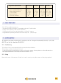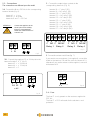
1
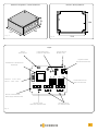
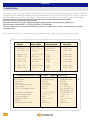
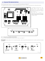
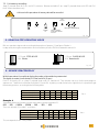
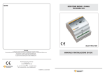
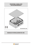
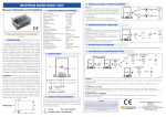
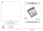
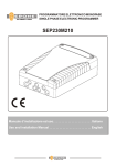
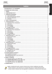
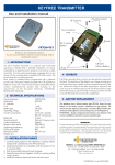
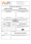
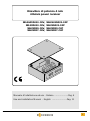
Ricevitore di potenza 4 relè
4 Relais power receiver
SEL2641R433-C4V,
SEL39R433-C4V,
SEL39R30-C4V,
SEL39R27-C4V,
SEL2641R433-C4P
SEL39R433-C4P
SEL39R30-C4P
SEL39R27-C4P
Manuale d’installazione ed uso - Italiano .....................Pag. 4
Use and installation Manual - English .......................Pag. 11
1
THE SMART LIVING
Misure di sicurezza
Per un perfetto funzionamento dell’apparecchio, si prega di
leggere interamente questo manuale e seguire attentamente
le indicazioni ivi descritte, in quanto l’uso improprio può
danneggiare l’apparecchio
?
Security measures
For a perfect functioning of the device, read carefully this
manual and follow all the indications, since an inadeguate
use can make damages to the device
Dichiarazione di Conformità:
Il costruttore Elpro Innotek Spa dichiara che il
radioprogrammatore mod. SEL2641R433-P4, SEL39R433P4, SEL39R30-P4 è conforme alle Direttive Europee
73/23/CEE, 89/336/CEE e 99/05/CE.
?
Declaration of Conformity:
Elpro Innotek Spa as manufacturer declares that the
following appliances : SEL2641R433-P4, SEL39R433-P4,
SEL39R30-P4 fullfil the requirements of the European
Directives 73/23/CEE, 89/336/CEE and 99/05/CE.
Presentazione / Introduction
Coperchio
Cover
4 viti per fissaggio del coperchio
4 screws for cover fixing
4 Viti per fissaggio della scatola
4 screws for box fixing
Passacavi
Wire leads
4 tasselli
4 plugs
Antenna
Aerial
Scatola con ricevitore e coperchio di protezione in plexiglass
Receiver box with plexiglas cover
Fig. 1
2
THE SMART LIVING
Interassi / Drilling distances
Dimensioni d’ingombro / Overall dimensions
52
104
140
115
Fig. 2
128
Fig. 3
Layout
Jumper Passo-Passo
Jumper for Step mode
Tasto P1
Push-button P1
Scheda radio RF
RF Radio card
Ingresso antenna
Antenna terminal board
Trasformatore di alimentazione
Transformer
ON
18 19
F1
Fusibile F1 : 3,15A - 250V
Fuse F1 : 3,15A - 250V
Led di attivazione relè
Relais activation LED
230V
1
2
L
N
6
7
8
9 10 11 12
Ch1
Ch2
13 14 15 16 17
Ch3
Ch4
Morsetti di alimentazione
Power Supply Terminal boards
Morsettiere di I/O
I/O Terminal boards
Morsetti di terra
GROUND Terminal boards
Fig. 4
3
THE SMART LIVING
ITALIANO
1 - DESCRIZIONE
Il ricevitore di potenza 4 relé è un ricevitore supereterodina con 4 uscite a contatti puri.
E’ stato concepito per comandare automatismi di chiusura e sistemi d’allarme con potenza massima di commutazione dei
contatti di 3,5 KW.
La frequenza e le tecnologie impiegate lo rendono conforme alle regolamentazioni europee in termini di
radiofrequenza e di compatibilità elettromagnetica (CE).
A seconda del modello ( ved. tabella ) cambia il tipo di codifica di sicurezza, che può essere rolling code ( Keeloq ® )
per i modelli della serie “2641” oppure a codice fisso per i modelli della seie “39”.
I contatti di uscita dei 4 relè possono essere NA ( per i relè 1 e 3 ) e NA/NC per i relè 2 e 4.
La potenza massima commutabile dai relè è di 3,5 KW a 230 Vac
La memorizzazione dei trasmettitori si effettua sia mediante i tasti del ricevitore per autoapprendimento.
I codici dei trasmettitori sono memorizzati in EEPROM.
La frequenza di ricezione e la codifica variano a seconda del modello. La seguente tabella riassume i sequenziali
della gamma Erone evidenziandone serie, modello, frequenza e tipo di codifica:
Il ricevitore viene prodotto in 8 modelli che differiscono per tensione di alimentazione, codifica di sicurezza e
frequenza:
Modello RX
Alimentazione
Codifica
Frequenza
SEL 2641 R433 C4P
SEL 2641 R433 C4V
12 / 24 Vac-dc
230 Vac
Rolling code
Rolling code
433,92 MHz
433,92 MHz
SEL 39 R433 C4P
SEL 39 R433 C4V
12 / 24 Vac-dc
230 Vac
3Exp9
3Exp9
433,92 MHz
433,92 MHz
SEL 39 R27 C4P
SEL 39 R27 C4V
12 / 24 Vac-dc
230 Vac
3Exp9
3Exp9
27,195 MHz
27,195 MHz
SEL 39 30 C4P
SEL 39 R30 C4V
12 / 24 Vac-dc
230 Vac
3Exp9
3Exp9
30,875 MHz
30,875 MHz
Caratteristiche comuni
Alim. 230Vac
Alim. 12/24 Vac-dc
Tipo ricevitore
Modulazione
Impedenza d'ingresso
Emissione dell'oscillatore locale
Tensione di alimentazione
Consumo max
Supereterodina
AM/ASK
50 Ohm
< -57 dBm
230 Vac
28 mA
Supereterodina
AM/ASK
50 Ohm
< -57 dBm
12 - 24 Vac-dc
200 mA @24 Vac
260 mA @12 Vac
Potenza massima applicabile
ai contatti dei relè
Temperatura di funzionamento
Grado di protezione
Dimensioni (mm )
Peso
Memorizzazione TX
3,5 KW / 230 Vac
-20°/+70°C
IP44
140 x 115 x 52
420 gr
autoapprendimento
3,5 KW / 230 Vac
-20°/+70°C
IP44
140 x 115 x 52
310 gr
autoapprendimento
Tab.1
4
THE SMART LIVING
Caratteristiche radio specifiche
Frequenza portante (MHz)
Frequenza dell’oscillatore locale
Frequenza intermedia
Larghezza di canale
Sensibilità d’ingresso
N° max di utenti memorizzabili
SEL2641R433
433.92
6.6128
10,7 MHz
> 25 KHz
-117 dBm
85
SEL39R433
433,92
6.6128
10,7 MHz
> 25 KHz
-117 dBm
100
SEL39R30
SEL39R27
30,875
30,420
455 KHz
12,5 KHz
-113 dBm
100
27.195
27.650
455 KHz
12,5 KHz
-113 dBm
100
Tab.2
4 - FUNZIONALITA'
- 85 / 100 tasti trasmettitore memorizzabili
- Autoapprendimento e cancellazione del codice del trasmettitore per mezzo di un solo tasto presente sul ricevitore
- Visualizzazione N° totale utenti memorizzati
- Sovrascrittura codice di Tx già presente in memoria
- Cancellazione completa della memoria sia da radiocomando
- Funzionamento programmabile del 4° relè : monostabile o bistabile
5 - INSTALLAZIONE
L’apparecchiatura è costruita in conformità con quanto previsto dalle Direttive Europee 89/336/CEE,
73/23/CEE nonché da quanto indicato nella Norma EN 60335-1.
5.1 - Posizionamento
La scelta della posizione del ricevitore è molto importante per ottenere un buon funzionamento del sistema.
Devono essere rispettate le seguenti condizioni:
- posizionare il ricevitore lontano da fonti di disturbo quali sistemi informatici, allarmi od altre emissioni radio.
- la distanza tra due ricevitori deve essere superiore a 1.5 metri.
5.2 - Fissaggio
Togliere il coperchio dal ricevitore. Fissare la scatola ad ogni angolo utilizzando viti e tasselli in dotazione o con viti
appropriate alla natura del supporto.
5
THE SMART LIVING
5.3 - Connessioni
2 - Collegare i contatti di uscita dei relè ai morsetti
corrispondenti (fig. 6):
Le connessioni sono differenti a seconda del modello.
1A- Collegare l'alimentazione 230 Vac ai morsetti
corrispondenti (fig. 4):
morsetto 1 = L linea
morsetto 2 = N neutro
morsetti 6 e 7 = PE Terra
morsetto 13 = C relè 3 (R3)
morsetto 14 = NA relè 3 (R3)
morsetto 15 = C relè 4 (R4)
morsetto 16 = NA relè 4 (R4)
morsetto 17 = NC relè 4 (R4))
ATTENZIONE : Collegare l’apparecchio
all’impianto elettrico
dell’edificio mediante
un interruttore magnetotermico
con apertura dei contatti di
Almeno 3 mm.
!
1
L
2
N
6
morsetto 8 = C relè 1 (R1)
morsetto 9 = NA relè 1 (R1)
morsetto 10 = C relè 2 (R2)
morsetto 11 = NA relè 2 (R2)
morsetto 12 = NC relè 2 (R2
7
Fig.5
8 9 10 11 12
C NA C NA NC
Relè 1
Relè 2
13 14 15 16 17
C NA C NA NC
Relè 3
Relè 4
Fig. 7
1B - Collegare l’alimentazione 12 o 24 Vac/dc ai
morsetti 3, 4, 5. (fig. 5):
morsetto 3 = + 24 Vac/dc
morsetto 4 = + 12 Vac/dc
morsetto 5 = 0
3 4 5
24 12 0
3 -Collegare l’antenna come segue (fig. 7):
- se collegate un'antenna (non in dotazione), collegare la
calza al morsetto 18, ed il centrale al morsetto 19; oppure
collegare il filo d'antenna in dotazione al morsetto 18.
6
7
18 19
Antenna
+ACFig. 6
Fig. 8
5.4 - Fusibile
Il Fusibile F1,montato solo nei modelli con alimentazione
a 230 Vac, ha la funzione di proteggere la scheda
elettronica.
6
THE SMART LIVING
6 - MEMORIZZAZIONE DEI TRASMETTITORI
La memorizzazione dei trasmettitori si effettua in modo sequenziale facendo uso del solo pulsante P1 presente sulla
scheda. La conferma delle operazioni viene indicata dai led DL1, DL2, DL3, DL4 posti i corrispondenza dei 4 relè.
Modulo Rf
La memorizzazione prevede di effettuare
delle pressioni successive del tasto P1.
L’accensione dei led LD1, LD2, LD3, LD4 è
ciclica: ad ogni pressione di P1 si accende
un led e si spegne il led precedente. (fig.
10)
Il led DL4 si accende stabilmente oppure
lampeggia a seconda della configurazione
del jumper J1 ( ved. cap. 8 )
Ingresso antenna
ON
Trasformatore
18 19
Fusibile
LED3 LED4
LED1 LED2
F1
230V
1
2
L
N
6
7
8
9 10 11 12
13 14 15 16 17
Ch2
Ch1
Ch4
Ch3
Fig. 9
LD1
LD2
LD3
LD4
Fig. 10
6.1 Memorizzazione di un Trasmettitore a 2 canali
La memorizzazione prevede di effettuare delle pressioni successive del tasto P1.
Esempio 1: Memorizzazione di un radiocomando bicanale con il tasto A che attiva il relè 1 ed il tasto B che
attiva il relè 2
LD1 si
spegne
LD1 si
accende
Tenere premuto P1
per 2 sec fino a
quando LD1 si
accende
Rilasciare
P1
Premere il tasto A del
trasmettitore da
memorizzare
LD2 si
accende
Premere
P1
LD2 si
spegne
Rilasciare
P1
Premere il tasto B del
trasmettitore da
memorizzare
Fig. 11
7
THE SMART LIVING
6.2 Memorizzazione di un Trasmettitore a 4 canali
La memorizzazione prevede di effettuare delle pressioni successive del tasto P1.
Esempio 2: Memorizzazione di un radiocomando quadricanale con le seguenti associazioni:
Tasto A
Tasto B
Tasto C
Tasto D
LD1 si
spegne
LD1 si
accende
Tenere premuto P1 per 2
sec fino a quando LD1 si
accende
LD2 si
accende
Premere il tasto A del
trasmettitore da
memorizzare
Rilasciare
P1
Rilasciare
P1
Premere il tasto C del
trasmettitore da
memorizzare
LD2 si
spegne
Premere il tasto B del
trasmettitore da
memorizzare
Rilasciare
P1
Premere
P1
LD3 si
spegne
LD3 si
accende
Premere
P1
Relé 1
Relé 2
Relé 3
Relé 4
LD4 si
accende
LD4 si
spegne
Rilasciare
P1
Premere
P1
Premere il tasto D del
trasmettitore da
memorizzare
Fig. 12
7 - CANCELLAZIONE DEI TRASMETTITORI
7.1 Cancellazione di un Trasmettitore
Premere e tenere premuto il pulsante P1per 2 sec. fino a quando si accende il led relativo al relè associato al tasto del
trasmettitore da cancellare.
Premere successivamente il tasto del trasmettitore da cancellare ( es. tasto A): il ricevitore dà conferma dell’avvenuta
cancellazione spegnendo il led LD1 e con 2 lampeggi contemporanei dei 2 led LD3 ( Rosso) ed LD4 (Verde ).
Esempio 3 : Cancellazione del tasto A del trasmettitore dal relè 1
LD1 si
accende
LD1 si
spegne
LD3 ed LD4 lampeggiano 2 volte
contemporaneamente
Tenere premuto P1 per 2 sec
fino a quando LD1 si
accende
Rilasciare
P1
Premere il tasto ( es. A) del
trasmettitore
da cancellare
8
THE SMART LIVING
Fig. 13
7.2 Cancellazione completa della memoria
Premere e tenere premuto il pulsante P1per 2 sec. fino a quando si accende il led LD1. Rilasciare e ripremere P1
successivamente fino a quando LD3 ed LD4 lampeggiano contemporaneamente 3 volte.
!
Al termine della procedura tutti i dati presenti in memoria vengono cancellati
LD1 si
spegne
LD1 si
accende
LD3 ed LD4 lampeggiano 3 volte
contemporaneamente
Tenere premuto P1 per 2 sec
fino a quando LD1 si
accende
Rilasciare
P1
Ripremere P1 fino a
quando LD1 si spegne
Fig. 14
8 - FUNZIONAMENTO PASSO-PASSO RL4
Il relè K4 è configurabile in funzionamento impulsivo o passo-passo a seconda della posizione del jumper J1. In
configurazione passo-passo il led Verde LD4 quando attivato durante le fasi di memorizzazione e cancellazione invece di
accendersi stabilmente, lampeggia.
J1 Aperto : IMPULSIVO
LD4 : Luce continua
J1 Chiuso : PASSO-PASSO
LD4 : Lampeggia
Fig. 15
9 - VISUALIZZAZIONE SPAZIO DI MEMORIA
Attraverso la seguente procedura è possibile risalire al numero di tasti trasmettitore presenti in memoria.
La visualizzazione avviene per mezzo dei led LD3 ( Rosso) ed LD4 ( Verde).
Premere P1 e verificare l’accensione del led LD1. Mantenere premuto P1.
Non appena il led LD1 si spegne rilasciare il tasto P1.
A questo punto inizia una sequenza di accensioni dei led LD3 (LR) ed LD4 (LV).
La sequenza esprime in notazione binaria il numero di tasti trasmettitore memorizzati.
Annotando la sequenza è possibile risalire a questo numero in base alla tabella seguente:
Led acceso
Peso colore verde
Peso colore rosso
1°
1
0
2°
2
0
3°
4
0
4°
8
0
5°
16
0
6°
32
0
7°
64
0
Tab.3
Esempio 4:
Sequenza di accensione led :
LR, LR, LV, LV, LR, LR, LR.
Il numero ottenuto sarà:
0 + 0 + 4 + 8 + 0 + 0 + 0 = 12
Perciò in memoria sono presenti 12 tasti trasmettitori.
9
THE SMART LIVING
ENGLISH
1 - DESCRIPTION
The power receiver is a superheterodyne receiver with 4 power outputs. It has been designed for the control of automatic
closing systems and anti-burglar systems with maximum power on the relay contacts of 3,5 KW. The decoding system can
be different depending upon the model ( Series “2641” with rolling code Keeloq and Series “39” with fixed code system.
The receiver has 2 output relays, with NO ( Normally open ) contacts and 2 relays with NO/NC
( Normally open and normally closed) contacts.
It can be connected to any type of appliance as gates, garage doors, rolling shutters, lighting, etc.)
The max power commutable is 3,5 KW @ 230 Vac for each relay.
The user codes can be memorised both with the receiver buttons and, via radio, in self-learning, using the
transmitter keys.
The receiver is produced in 8 different versions with different power supply, frequency and decoding system:
RX Type
Power supply
Security system
Frequency
SEL 2641 R433 C4P
SEL 2641 R433 C4V
12 / 24 Vac-dc
230 Vac
Rolling code
Rolling code
433,92 MHz
433,92 MHz
SEL 39 R433 C4P
SEL 39 R433 C4V
12 / 24 Vac-dc
230 Vac
3Exp9
3Exp9
433,92 MHz
433,92 MHz
SEL 39 R27 C4P
SEL 39 R27 C4V
12 / 24 Vac-dc
230 Vac
3Exp9
3Exp9
27,195 MHz
27,195 MHz
SEL 39 30 C4P
SEL 39 R30 C4V
12 / 24 Vac-dc
230 Vac
3Exp9
3Exp9
30,875 MHz
30,875 Mhz
Common specifications Supply 230Vac
Supply 12/24 Vac-dc
Receiver type
Modulation
Input load
Local oscillator emissions
Supply voltage
Current consumption (max )
Superheterodyne
AM/ASK
50 Ohm
< -57 dBm
230 Vac
28 mA
Max relays contact power
Operating temperature
IP grade protection
Dimensions (mm )
Weight
Transmitters Memorization
3,5 KW / 230 Vac
-20°/+70°C
IP44
140 x 115 x 52
420 gr
selflearning
Superheterodyne
AM/ASK
50 Ohm
< -57 dBm
12 - 24 Vac-dc
200 mA @24 Vac
260 mA @12 Vac
3,5 KW / 230 Vac
-20°/+70°C
IP44
140 x 115 x 52
310 gr
selflearning
Tab.1
10
THE SMART LIVING
Single radio specifications
Carrier frequency (MHz)
Local oscillator frequency
Intermediate frequency
Channel width
Input sensitivity
User code number
SEL2641R433 SEL39R433
433.92
6.6128
10,7 MHz
> 25 KHz
-117 dBm
85
433,92
6.6128
10,7 MHz
> 25 KHz
-117 dBm
100
SEL39R30
30,875
30,420
455 KHz
12,5 KHz
-113 dBm
100
SEL39R27
27.195
27.650
455 KHz
12,5 KHz
-113 dBm
100
Tab.2
4 - MAIN FEATURES
- 85 / 100 transmitter keys memory
- Self-learning and cancellation of transmitter code with 1 push-button
- Display of the number of the stored transmitters
- Cancellation either of the single transmitter or of the full memory
- Programmable operating mode for the fourth relay RL4 : pulse or step.
5 - INSTALLATION
The appliance has been manufactured in compliance with the European Directives 89/336/CEE, 73/23/CEE,
99/5/CE and with the Regulation EN 60335-1.
5.1 - Positioning
The location choice is very important for the best result of the installation.
The following conditions have to be followed:
- Fix the receiver far from interference sources as informatic systems, allarm systems or other radio emissions.
- the distance between 2 receivers should be more than 1.5 m.
5.2 - Fixing
Remove the cover of the receiver; fix the box in each corner by using the screws and the plugs supplied..
11
THE SMART LIVING
5.3 - Connections
The connections are different upon the model.
2 - Connect the output relays contacts to the
corresponding terminals ( Fig. 6):
1A- Connect the Mains 230 Vac to the corresponding
terminal boards (fig. 4):
terminal 1 = L Line
terminal 2 = N neutre
terminals 6 and 7 = PE Gnd
ATTENTION :
terminal 13 = C relay 3 (R3)
terminal 14 = NO relay 3 (R3)
terminal 15 = C relay 4 (R4)
terminal 16 = NO relay 4 (R4)
terminal 17 = NC relay 4 (R4))
Connect the appliance to the
electric plant of the building
through a magnetothermic
switch with contact distance of
at least 3 mm.
!
terminal 8 = C relay 1 (R1)
terminal 9 = NO relay 1 (R1)
terminal 10 = C relay 2 (R2)
terminal 11 = NO relay 2 (R2)
terminal 12 = NC relay 2 (R2)
8 9 10 11 12
C NO C NO NC
Relay 1 Relay 2
1
L
2
N
6
13 14 15 16 17
C NO C NO NC
Relay 3 Relay 4
7
Fig. 7
Fig.5
3 -Connect the antenna as follows (fig. 7):
1B - Connect the supply at 12 or 24 Vac/dc to the
terminal boards 3, 4, 5. (fig. 5):
terminal 3 = + 24 Vac/dc
terminal 4 = + 12 Vac/dc
terminal 5 = 0
if you want to use an antenna,( not supplied), connect the
shield to the terminal 18 and the net to the terminal 19,
otherwise if you use the antenna cable supplied, connect it
to the terminal 19.
18 19
3 4 5
24 12 0
6
7
Antenna
Fig. 8
+ACFig. 6
5.4 - Fuse
The fuse F1 is only present on the receivers supplied at
230 Vac.
The fuse F1 of 315 mA needs for the electronic card
protection.
12
THE SMART LIVING
6 - TRANSMITTER MEMORIZATION
The transmitter memorization is carried out sequentially using the push-button P1.
The system gives the operation confirmation with the led DL1, DL2, DL3, DL4 located above the corresponding relay.
Module Rf
The lighting of the leds LD1, LD2,
LD3, LD4 is cyclic: at every
pressure of P1 a led is turned on
and the preceding led is turned
off. (Fig. 10 )
The led DL4 is turned on
continously or flashes according
to the configuration of the jumper
J1 (see. cap. 8 )
Antenna
P1
Transformer
ON
18 19
Fuse
LED1
LED2
LED3
LED4
F1
230V
1
2
L
N
6
7
8
9
Ch1
10 11 12
13 14 15 16 17
Ch2
Ch4
Ch3
Fig. 9
LD1
LD2
LD4
LD3
Fig. 10
6.1 2 channel transmitter memorization
The procedure is effected with some pressures of the push-button P1.
Example 1: Memorization of a 2 channel transmitter with the key A that activates the relay 1 and the key B that activates
the relay 2.
LD1
turns off
LD1
turns on
Keep P1 pressed
down for 2 sec.
until LD1 comes
on
Release
P1
Press the
transmitter key A
to memorize
LD2
turns on
Push
P1
LD2
turns off
Release
P1
Press the
transmitter key B to
memorize
Fig. 11
13
THE SMART LIVING
6.1 2 channel transmitter memorization
The procedure is effected with some pressures of the push-button P1.
Example 1: Memorization of a 2 channel transmitter with the key A that activates the relay 1 and the key B that activates
the relay 2.
KEY1
KEY2
KEY3
KEY4
LD1
turns off
LD1
turns on
Keep P1 pressed
down for 2 sec. until
LD1 comes on
Release
P1
Press the
transmitter key A
to memorize
LD2
turns on
Press the
transmitter key C
to memorize
Release
P1
LD2
turns off
Release
P1
Push
P1
LD3
turns off
LD3
turns on
Push
P1
Relay1
Relay2
Relay3
Relay4
Press the
transmitter key B to
memorize
LD4
turns on
LD4
turns off
Release
P1
Push
P1
Press the
transmitter key D to
memorize
Fig. 12
7 - TRANSMITTERS CODE CANCELLING PROCEDURE
7.1 Single transmitter cancelling
Keep P1 pressed down for 2 sec. until the led corresponding to the relay associated to the key remains lit.
Next push the transmitter key to cancel ( example Key A ) : the receiver gives the confirmation by turning off the led and
with 2 flashes of both the led LD3 ( Red) and LD4 (Green ).
Example 3 : Cancellation of the transmitter key A from the relay 1.
LD1
turns on
LD1
turns off
LD3 and LD4
blink twice simultaneously
Keep P1 pressed
down for 2 sec. until
LD1 comes on
Release
P1
Press the transmitter
key A to cancel ( ex A)
Fig. 13
14
THE SMART LIVING
7.2 Full memory cancelling
Keep P1 pressed down for 2 sec. until LD1 comes on. Release and within 2 sec. keep P1 pressed down until LD3 and LD4
blink 3 times simultaneously.
!
At the end of the procedure all memory data will be cancelled.
LD1
turns off
LD1
turns on
LD3 and LD4
blink 3 times simultaneously
Release
P1
Keep P1 pressed
down again until LD1
turns off
Fig. 14
8 - RELAY RL4 STEP OPERATING MODE
RL4 can operate in step-mode according to the position of jumper J1 ( see figure 2 below ).
In step mode, during the memorization and cancellation phases, LD4 blinks instead to remain lit
J1 Open : PULSE-MODE
LD4 : Remains Lit
J1 Closed : STEP-MODE
LD4 : Blinks
Fig. 15
9 - MEMORY SPACE DISPLAY
With this procedure it is possible to display the number of transmitter keys memorized
The display is carried on with the led LD3 ( Red) and LD4 ( Green ).
Push P1 and verify LD1 on. Keep P1 pressed down until LD1 switches off. Then release it at once. At this point begins a
sequence of 7 total blinks of the two led lights LD3 and LD4: by taking a note of what color light blinks, it is possible to get
the memory position, according to the following table:
Led blink number 1
Green Blink (LV)
Red Blink (LR)
Total blinks
2
1
0
3
2
0
4
4
0
5
8
0
6
16
0
7
32
0
64
0
Tab.3
Example 4:
Transmitter blinks the following seven times after pushing the button P1:
RED - RED - GREEN - GREEN - RED - RED - RED
Then one whould fill in table 1 as follows:
Led blink number 1
Green Blink (LV)
Red Blink (LR)
Total blinks
2
1
0
0+
3
2
0
0+
4
4
0
4+
5
8
0
8+
6
16
0
0+
7
32
0
0+
64
0
0+
Tab.4
This corresponds to the 12th position.
15
THE SMART LIVING
Note
Garanzia
Guarantee
Guarantee period: 24 months from the productions date placed inside.
In this period if the appliance has any malfunction due to a defective component,it will be
repaired or replaced by the manufacturer.
The warranty doesn't cover the plastic box.
The assistance will be performed at the manufacturer site.
THE SMART LIVING
Manufactured by Elpro Innotek SpA
Via Piave, 23
I-31020 S.Pietro di Feletto (TV)
Italy
Tel. +39-0438-450860 - Fax . +39-0438-455628
Web : www.erone.com - email: [email protected]
IS-RP4ERML Rev.2 del 7/09/2004
La garanzia è di 24 mesi dalla data di fabbricazione apposta all’interno.
Durante tale periodo, se l’apparecchiatura non funziona correttamente, a causa di un
componente difettoso, essa verrà riparata o sostituita a discrezione del fabbricante.
La garanzia non copre l’integrità del contenitore plastico.
La garanzia viene prestata presso la sede del fabbricante.