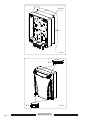
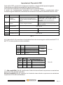
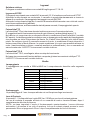
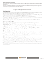
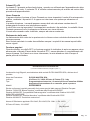
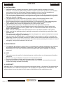
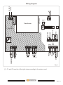
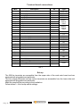
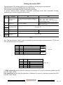
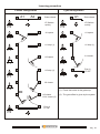
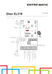
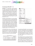
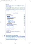
1
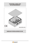
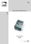
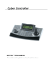
THE SMART LIVING
PROGRAMMATORE ELETTRONICO MONOFASE
SINGLE PHASE ELECTRONIC PROGRAMMER
SEP230M210
Manuale d’installazione ed uso. . . . . . . . . . . . . . . . . . . . . . . Italiano
Use and installation Manual . . . . . . . . . . . . . . . . . . . . . . . . . English
THE SMART LIVING
ITALIANO
AVVERTENZE
ITALIANO
A.1 INSTALLAZIONE
!
!
!
!
!
!
!
!
!
!
!
!
!
ATTENZIONE! Per la sicurezza delle persone, prima di iniziare l’installazione del prodotto leggere
attentamente questo manuale e conservarlo per riferimenti futuri. Esso è rivolto a personale tecnico
abilitato all’installazione di “Apparecchi utilizzatori di energia elettrica” ai sensi della legge N.46 del
5.3.1990 e richiede una buona conoscenza della tecnica, esercitata professionalmente e
l’osservanza della legislazione locale, nazionale ed europea vigente. Una errata installazione o un
errato uso può portare gravi danni alle persone.
Questo prodotto è stato progettato e costruito esclusivamente per l’utilizzo indicato in questa
documentazione. Qualsiasi altro utilizzo non espressamente indicato potrebbe pregiudicare
l’integrità del prodotto e/o rappresentare fonte di pericolo.
Gli elementi costruttivi meccanici devono essere in accordo con quanto stabilito dalle Norme EN
12604 e EN 12605. Per i Paesi extra-CEE, oltre ai riferimenti normativi nazionali, per ottenere un
livello di sicurezza adeguato, devono essere seguite le Norme sopra riportate.
Il costruttore non è responsabile dell’inosservanza della Buona Tecnica nella costruzione delle
chiusure da motorizzare, nonché delle deformazioni che dovessero intervenire nell’utilizzo.
Non installare il prodotto in ambienti a pericolo di esplosione o disturbati da campi elettromagnetici.
La presenza di gas o fumi infiammabili costituisce un grave pericolo per la sicurezza.
L’installazione deve essere effettuata nell’osservanza delle Norme EN 12453 e EN 12445.
Prima di effettuare qualsiasi intervento sull’impianto, togliere l’alimentazione elettrica.
Nel caso in cui non sia incluso nel prodotto, prevedere sulla rete di alimentazione, a monte
dell’apparecchiatura un interruttore magnetotermico da 10A con interruzione omnipolare con
distanza d’apertura dei contatti uguale o superiore a 3 mm.
Verificare inoltre che a monte dell’impianto vi sia un interruttore differenziale con soglia da 0,03 A.
Verificare che l’impianto di terra sia realizzato a regola d’arte e collegarvi le parti metalliche della
chiusura.
I dispositivi di sicurezza (norma EN 12978) permettono di proteggere eventuali aree di pericolo da
rischi meccanici di movimento, come ad es. schiacciamento, convogliamento, cesoiamento.
Per ogni impianto è consigliato l’utilizzo di almeno una segnalazione luminosa nonché di un cartello di
segnalazione fissato adeguatamente sulla struttura dell’infisso, oltre ai dispositivi citati al punto
precedente.
L’installatore deve fornire tutte le informazioni relative al funzionamento manuale del sistema in caso
di emergenza e consegnare questo manuale all’Utente utilizzatore dell’impianto.
A.2 MANUTENZIONE
!
Per garantire l’efficienza del prodotto è indispensabile che venga eseguita una manutenzione
periodica da personale qualificato. Gli interventi di installazione, manutenzione e pulizia devono
essere documentati e la documentazione deve essere conservata dall’utilizzatore e tenuta a
disposizione del personale preposto al controllo.
A.3 UTILIZZO
!
!
!
!
Il prodotto è destinato all’uso per il quale è stato concepito. Ogni altro utilizzo è da considerarsi
improprio o pericoloso.
Non eseguire alcuna modifica sui componenti facenti parte del sistema d’automazione.
Non permettere ai bambini o persone di sostare nelle vicinanze del prodotto durante il funzionamento.
Tenere fuori dalla portata dei bambini radiocomandi o qualsiasi altro datore di impulso, per evitare che
l’automazione possa essere azionata involontariamente.
A.4 GARANZIA
La garanzia è di 24 mesi dalla data di fabbricazione apposta all’interno.
Durante tale periodo, se l’apparecchiatura non funziona correttamente, a causa di un componente
difettoso, essa verrà riparata o sostituita a discrezione del fabbricante.
La garanzia non copre l’integrità del contenitore plastico. La garanzia viene prestata presso la sede del
fabbricante
Pag . 2
THE SMART LIVING
INDICE
Avvertenze . . . . . . . . . . . . . . . . . . . . . . . . . . . . . . . . . . . . . . . . . . . . . . . . . . . . pag. 2
Presentazione . . . . . . . . . . . . . . . . . . . . . . . . . . . . . . . . . . . . . . . . . . . . . . . . . . pag. 3
Caratteristiche tecniche. . . . . . . . . . . . . . . . . . . . . . . . . . . . . . . . . . . . . . . . . . . pag. 4
Installazione . . . . . . . . . . . . . . . . . . . . . . . . . . . . . . . . . . . . . . . . . . . . . . . . . . . pag. 5
Schema generale collegamenti . . . . . . . . . . . . . . . . . . . . . . . . . . . . . . . . . . . . pag. 7
Legenda morsetti. . . . . . . . . . . . . . . . . . . . . . . . . . . . . . . . . . . . . . . . . . . . . . . . pag. 8
Configurazione dell’apparecchiatura . . . . . . . . . . . . . . . . . . . . . . . . . . . . . . . . . pag. 8
Impostazione dei dip-switch . . . . . . . . . . . . . . . . . . . . . . . . . . . . . . . . . . . . . . . pag. 9
Modi di funzionamento . . . . . . . . . . . . . . . . . . . . . . . . . . . . . . . . . . . . . . . . . . . pag. 10
Operazioni preliminari . . . . . . . . . . . . . . . . . . . . . . . . . . . . . . . . . . . . . . . . . . . pag. 10
Procedura di apprendimento . . . . . . . . . . . . . . . . . . . . . . . . . . . . . . . . . . . . . . . pag. 10
Descrizione ingressi . . . . . . . . . . . . . . . . . . . . . . . . . . . . . . . . . . . . . . . . . . . . . pag. 11
Descrizione uscite . . . . . . . . . . . . . . . . . . . . . . . . . . . . . . . . . . . . . . . . . . . . . . . pag. 13
Logica e dettagli di funzionamento . . . . . . . . . . . . . . . . . . . . . . . . . . . . . . . . . . pag. 14
Gestione dei radiocomandi . . . . . . . . . . . . . . . . . . . . . . . . . . . . . . . . . . . . . . . . pag. 15
Dichiarazione di conformità . . . . . . . . . . . . . . . . . . . . . . . . . . . . . . . . . . . . . . . . pag. 15
Presentazione
Il programmatore SEP230M210 è una centrale di comando a microprocessore adatta al
comando di 1 o 2 motori asincroni monofase da 230V / 450W , senza fine corsa.
L’elettronica è equipaggiata con un ricevitore supereterodina integrato, funzionante a 433
MHz con decodifica del tipo KeeLoq® Hopping code.
Particolarmente innovativo è il sistema di soft start-stop dei motori, con sense di corrente ed
estrema facilità di messa a punto.
E’ realizzata in conformità con tutte le Direttive Europee applicabili e le normative specifiche di
prodotto.
L'apparecchiatura è dotata di sicurezza intrinseca, che auto-regola la forza di spinta in
funzione della corrente assorbita; riconosce gli ostacoli durante la corsa, arretra l'anta di
qualche cm per liberare l'ostacolo, e si ferma in attesa di comando oppure inverte il moto
secondo la configurazione impostata.
Il tempo di pausa è regolabile a mezzo trimmer ( fino a 200 sec.).
Si possono impostare 4 modi di funzionamento:
!
ad azione mantenuta ( uomo presente ),
!
semiautomatico,
!
automatico con inversione ad ogni comando,
!
automatico con stop ad ogni comando.
L'apparecchiatura è alloggiata in contenitore plastico IP55 con grado di ignifugazione
UL94-V0.
THE SMART LIVING
Pag . 3
Caratteristiche tecniche
Programmatore
Alimentazione. . . . . . . . . . . . . . . . . . . . . . . . . . . . . . . . . . . . . . . . . . . . . 230 Vac ±10%
Frequenza . . . . . . . . . . . . . . . . . . . . . . . . . . . . . . . . . . . . . . . . . . . . . . . . . . . . . . 50 Hz
N° motori collegabili. . . . . . . . . . . . . . . . . . . . . . . . . . . . . . . . . . . . . . . . . . . . . . . . . . . 2
Alimentazione motori . . . . . . . . . . . . . . . . . . . . . . . . . . . . . . . . . . . . . . . . . . . . 230 Vac
Potenza motori . . . . . . . . . . . . . . . . . . . . . . . . . . . . . . . . . . . . . . . . . . . . . . . . 2 x 450W
Corrente nominale . . . . . . . . . . . . . . . . . . . . . . . . . . . . . . . . . . . . . . . . . . . . . . . . . . 4 A
Temperatura di esercizio . . . . . . . . . . . . . . . . . . . . . . . . . . . . . . . . . . . . . . . -20 / +85°C
Grado di protezione contenitore. . . . . . . . . . . . . . . . . . . . . . . . . . . . . . . . . . . . . . . IP55
Grado di ignifugazione (UL94) . . . . . . . . . . . . . . . . . . . . . . . . . . . . . . . . . . . . . . . . . V0
Dimensioni (mm) . . . . . . . . . . . . . . . . . . . . . . . . . . . . . . . . . . . . . . . . . 319 x 223 x 100
Peso:. . . . . . . . . . . . . . . . . . . . . . . . . . . . . . . . . . . . . . . . . . . . . . . . . . . . . . . . . . 2,4 Kg
Alimentazione lampeggiante . . . . . . . . . . . . . . . . . . . . . . . . . . . . . . 230 Vac 40 Wmax
Alimentazione luce di cortesia . . . . . . . . . . . . . . . . . . . . . . . . . . . . 230 Vac 150 Wmax
Alimentazione fotocellule . . . . . . . . . . . . . . . . . . . . . . . . . . . . . . . . . . 12 Vac - 100 mA
Alimentazione ausiliaria . . . . . . . . . . . . . . . . . . . . . . . . . . . . . . . . . . . 12 Vac - 200 mA
Tempo di pausa . . . . . . . . . . . . . . . . . . . . . . . . . . . . . . . . . . . . . . . . . . . . . 3 - 200 sec
Ricevitore radio integrato
Tipo di ricevitore:...................................................................................Supereterodina
Demodulazione: ...............................................................................................AM/ASK
Frequenza: .................................................................................................433,92 MHz
Frequenza dell’oscillatore locale: ...............................................................6,6128 MHz
Frequenza intermedia: ...................................................................................10,7 MHz
Sensibilità ( per segnale a buon fine ):...........................................................-117 dBm
Impedenza d’ingresso:......................................................................................50 Ohm
Memoria tasti tx: ........................................................................................................85
Temperatura di funzionamento:..................................................................-20 / +70 °C
Decodifica.................................................................................Keeloq® Hopping code
Pag . 4
THE SMART LIVING
Installazione
1) In base alla tipologia dell’impianto, individuare la posizione migliore dell’apparecchiatura in
modo che sia in prossimità del cancello, al riparo da urti e manomissioni, ad altezza sufficiente
dal suolo, al riparo da colmi d’acqua e facilmente raggiungibile dal tecnico per interventi di
manutenzione.
2) Aprire il coperchio del contenitore svitando le 4 viti che rimangono prigioniere ed assicurarsi
dell’integrità dell’apparato elettronico (Fig. 2).
3) Tracciare con l’aiuto della scatola i 4 punti di fissaggio o tenendo presenti gli interassi
indicati in Fig. 1
4) Praticare i fori Ø6 mm per fissare i tasselli e fissare l’apparecchiatura con 4 viti autofilettanti
M4.
5) Innestare i passacavi ( se forniti ) attraverso i fori presfondati e far passare i cavi di
collegamento tenendo separati quelli di potenza da quelli di comando.
6) Nel caso non sia fornito con l’apparecchiatura, collegare a monte della linea principale di
alimentazione un interruttore magnetotermico bipolare da 6A con distanza dei contatti di
almeno 3 mm.
Verificare inoltre la presenza di un interruttore differenziale da 30 mA a monte del
collegamento di linea.
7) Eseguire le connessioni facendo riferimento allo schema di Fig. 3 ed alla tabella Tab. 2.
THE SMART LIVING
Pag . 5
Ø 6mm
195.4
285.4
Fig. 1
67 mm
2x
52 mm
2x
Pag . 6
Fig. 2
THE SMART LIVING
24 25
POWER
F 230 V
N 230 V
Schema generale dei collegamenti
F1
26 27
L1
P3
Trasformatore
1 2
Fusibile 5A
3
4
5
6
7
SW1
8
P1
P2
FTC
FTC-S
CHIUDE
APRE
RV1
17 18 19 20 21 22 23
8 9 10
M1
M2
C1
C2 (*)
12Vac
0V
12Vac
0V
5 6 7
STOP
LP
L. CORTESIA
1 2 3 4
TX
AUX FTC
11 12 13 14 15 16
Fig. 3
(*) : C1 e C2 devono essere di capacità adatta ai motori collegati.
THE SMART LIVING
Pag . 7
Legenda Morsetti
Mors. N°
1
2
3
4
5
6
7
8
9
10
11
12
13
14
15
16
17
18
19
20
21
22
23
24
25
26
27
Descrizione
I/U
Luce di cortesia
Luce di cortesia
Lampeggiante
Lampeggiante
M1 Chiusura
M1 Comune
M1 Apertura
M2 Apertura
M2 Comune
M2 Chiusura
Alimentazione Aux
Alimentazione Aux
Alimentazione Fotocellule
Alimentazione Fotocellule
Contatto elettrico stop
Contatto elettrico stop
Contatto elettrico Apertura
Comune
Contatto elettrico Chiusura
Contatto Fotocellula di Stop
Contatto Fotocellula di Stop
Contatto Fotocellula di Riapertura
Contatto Fotocellula di Riapertura
Fase alimentazione 230V
Neutro alimentazione 230V
GND Antenna RX radio
Antenna RX radio
Uscita
Uscita
Uscita
Uscita
Uscita
Uscita
Uscita
Uscita
Uscita
Uscita
Uscita
Uscita
Uscita
Uscita
Ingresso
Ingresso
Ingresso
Ingresso
Ingresso
Ingresso
Ingresso
Ingresso
Ingresso
Ingresso
Ingresso
Ingresso
Ingresso
Tipo
F 230 Vac
N 230 Vac
F 230 Vac
N 230 Vac
Motore1
230Vac
450W
Motore2
230Vac
450W
12 Vac
0V
12 Vac
0V
C
NC
NA
C
NA
NC
C
C
NC
F 230 Vac
N 230 Vac
RG58
Tab. 2
Configurazione dell’apparecchiatura
I terminali 230V sono accessibili sulla parte superiore della scheda e dotati di morsettiere
estraibili.
I terminali per lampeggiante, luce di cortesia, motori e per gli ingressi in bassa tensione sono
accessibili nella parte inferiore e dotati di morsettiere estraibili.
Eseguire i collegamenti secondo le dotazioni prescelte.
La configurazione dei dip-switch segue quanto riportato nella tabelle 3 e 4.
Pag . 8
THE SMART LIVING
Impostazioni Dip-switch SW1
Il dip-switch SW1 consente di configurare l’impianto, a seconda delle proprie esigenze.
L’impostazione di fabbrica prevede tutti i dip in posizione ON.
Ciò consente di realizzare un impianto dalle seguenti caratteristiche:
2 motori con funzionamento automatico con richiusura, funzione condominiale attiva,
funzione seguimi disattivata, test attivato su entrambe le fotocellule,sensibilità ostacolo: alta
DIP N°
Funzione
ON
OFF
Comando di moto dinamico in apertura e
chiusura ( apre – chiude – apre – chiude.. )
oppure ( apre – stop – chiude – stop..) a
seconda del modo di funzionamento
impostato.
Funzione “Seguimi” attiva : al ripristino del
fascio infrarosso FTC interrompe tempo di
pausa e richiude
1
Funzione
condominiale
E’ attivo solo il comando di apertura.
Durante la pausa, alla ricezione di un
comando il tempo impostato dal trimmer
riparte.
2
Seguimi
Funzione “Seguimi” disattiva
3
4
Modo di
funzionamento
5
Test su FTC-S (#)
Test su Fotocellula FTC-S abilitato
Test su Fotocellula FTC-S disabilitato
6
Test su FTC (#)
Test su Fotocellula FTC abilitato
Test su Fotocellula FTC disabilitato
7
8
Ved. Tab. 4A
Sensibilità ostacolo
Ved. Tab. 4B
Tab. 3
(#) : I dip switch 5 e 6 consentono di escludere il test che viene eseguito sulle fotocellule FTC-S
ed FTC, in caso queste non siano installate.
Dip 3
Dip 4
Modo di funzionamento
ON
ON
Automatico ( con inversione )
ON
OFF
Automatico ( con stop )
OFF
ON
OFF
OFF
Semiautomatico
Azione mantenuta ( Uomo
presente )
Richiusura
automatica
Abilitata
Disabilitata
ON
Livello
Sensibilità ostacolo (*)
4
molto sensibile (5%)
OFF
ON
3
sensibile (10%)
ON
OFF
2
sensibile (15%)
OFF
OFF
1
poco sensibile (20%)
Dip 7
Dip 8
ON
Tab. 4A
Tab. 4B
(*) : Alta sensibilità ( Liv. 4), significa che l’ostacolo viene rilevato se provoca una variazione
superiore al 5% dei livelli standard.
Bassa sensibilità ( Liv. 1), significa che l’ostacolo viene rilevato se provoca una variazione
superiore al 20% dei livelli standard.
THE SMART LIVING
Pag . 9
Modi di funzionamento
Modo Automatico:
il ciclo inizia con un comando di moto, comprende le fasi di apertura (LP con intermittenza
lenta), pausa (LP con intermittenza molto lenta) e chiusura (LP con intermittenza veloce);
il ciclo si chiude con l'arrivo in battuta o con l'intervento del fine corsa di chiusura.
Ad ogni comando il moto si inverte. La richiusura automatica è abilitata.
Modo Automatico con Stop
Il modo automatico con stop differisce da quello automatico per la presenza dello stop tra le
fasi di apertura e chiusura.
La richiusura automatica è abilitata.
Modo Semiautomatico
Il modo semiautomatico inizia con un comando di moto e termina alla fine del singolo ciclo ( in
apertura con cancello completamente aperto o in chiusura con cancello completamente
chiuso).
Non vi è richiusura automatica.
Modo Azione mantenuta ( Uomo Presente )
In questa modalità vi è movimento delle ante solo se il comando viene mantenuto: al rilascio
ogni movimento cessa istantaneamente.
Il questa modalità il lampeggiante LP ha una intermittenza rapida.
Modo Allarme
In questa modalità il funzionamento è identico al modo Uomo Presente.
Vedere il paragrafo “Logica e dettagli di funzionamento” per le condizioni in cui si verifica .
Operazioni preliminari
1 - Effettuare tutte le connessioni, seguendo lo schema di Fig. 5.
2 - Inserire l’eventuale ricevitore a scheda nell’apposito connettore, posto sulla scheda base
dell’apparecchiatura.
3 - Impostare i dip-switches A e B in base alla configurazione d’impianto ed al modo di
funzionamento desiderato.
E’ consigliabile impostare inizialmente il funzionamento a Uomo Presente ( dip3=OFF,
dip4=OFF) per verificare il corretto senso di apertura delle ante, prima di procedere con
l’apprendimento dei tempi di viaggio.
NB: Reimpostare successivamente la configurazione ( dip3=ON, dip4=ON) per
procedere con l’apprendimento.
Pag . 10
THE SMART LIVING
Procedura di apprendimento
Configurazione a 1 anta
Configurazione a 2 ante
A1
P2
A2
A1
Ante chiuse
LP lampeggia
rapidamente
P2
LP lampeggia
rapidamente
A1 apre
A1 apre
P1
Anta chiusa
P1
A1 stop (1)
A1 stop (1)
P1
P1
A1 chiude
A2 apre
P2
P1
Fine (1)
LP Spento
A2 stop (1)
P2
P1
A2 chiude
P2
(1) : premere il pulsante in prossimità
della battuta
A2 chiude
& A1 chiude (2)
(2) : Lo sfalsamento d’anta è calcolato
automaticamente dal sistema
Fine (1)
LP Spento
P2
Fig. 4
THE SMART LIVING
Pag . 11
Ingressi
Selettore a chiave
Collegare un selettore a chiave con contatti NA agli ingressi 17-18-19.
Ingresso di STOP
Collegando un pulsante con contatto NC ai morsetti 15-16 si realizza una funzione di STOP.
Attivando lo stop durante un movimento, il cancello si arresta istantaneamente e rimane in
attesa di un comando: il lampeggiante lampeggia in modo RAPIDO
Attivando lo stop durante la pausa, il cancello di arresta definitivamente e non richiude anche
se richiusura automatica è abilitata.
In questa condizione, a differenza dello stato di pausa normale, il lampeggiante è spento.
Fotocellula FTC
La fotocellula FTC se interviene durante la chiusura provoca l’inversione del moto.
E’ soggetta al test di funzionamento prima di ogni chiusura ( vedere dettagli a pag. 13)
Nel caso in cui venga ricevuto un comando di moto in condizione di fascio interrotto ( contatto
NC aperto), il sistema segnala la condizione con un lampeggio molto rapido del lampeggiante
che permane per tutta l’interruzione del fascio. Se il fascio viene liberato, tutto ritorna come
prima. Se vengono ricevuti 3 comandi successivi di moto, in condizione di fascio interrotto, il
sistema commuta in Modo Allarme. In questa condizione è in ogni caso possibile attuare un
moto ( tramite selettore a chiave, comando ausiliario o radiocomando ) con un comando ad
azione mantenuta. Il LED FTC è acceso se il contatto è chiuso.
Fotocellula FTC-S
La fotocellula FTS-S, se collegata, attua uno stop del movimento.
Nel caso sia connessa ed il test sia abilitato, comporta gli stessi meccanismi validi per FTC.
Il LED FTC-S è acceso se il contatto è chiuso.
Uscite
Lampeggiante
Il lampeggiante con uscita a 230Vac/40W ha il comportamento descritto nella seguente
tabella:
Stato
Cancello chiuso
Apertura
Pausa
Funzionamento lampeggiante
Luce SPENTA
Lampeggio LENTO
Lampeggio molto LENTO
Chiusura
Lampeggio VELOCE
Allarme
Lampeggio RAPIDO
Uomo presente
Lampeggio RAPIDO
Autoapprendimento
Lampeggio RAPIDO
Stop
Lampeggio RAPIDO
Tab. 6
Prelampeggio
Un prelampeggio di 1 sec. è sempre attivato e si verifica prima di ogni movimento.
Luce di Cortesia
Ai morsetti 1 - 2 è disponibile un’uscita 230 Vac / 150W per una luce di cortesia esterna.
La luce di cortesia si accende all’inizio di un comando di moto e termina 30 sec. dopo il
completamento del ciclo di chiusura.
NOTA: se viene impostato il modo di funzionamento semiautomatico ( senza richiusura
automatica ) al termine di un ciclo di apertura, la luce di cortesia rimane accesa in modo
permanente. Essa si spegne solo 30 sec. dopo il completamente del ciclo di chiusura.
Pag . 12
THE SMART LIVING
Alimentazione Fotocellule
AI morsetti 13, 14 è disponibile un’uscita a 12 Vac / 100 mA per l’alimentazione separata delle
fotocellule.
Questo consente di effettuare un test del funzionamento delle fotocellule prima di ogni moto,
ai sensi dei requisiti della Normativa EN-12978.
Logica e dettagli di funzionamento
Test Fotocellule
In conformità con quanto previsto dalla normativa EN 12978, l’apparecchiatura effettua un test
di funzionamento delle fotocellule FTC prima di ogni movimento di chiusura.
Il test consiste nell’interruzione dell’alimentazione delle fotocellule ( morsetti 13 - 14 ) e la
verifica che il corrispondente contatto FTC e/o FTC-S si interrompe.
Se per qualunque ragione il test fallisce, la centralina commuta in Modo Allarme.
In condizione di Allarme è in ogni caso possibile movimentare le ante con un’azione mantenuta
del comando ( sia a filo sia via radio).
Se la fotocellula riprende a funzionare, il sistema esce automaticamente dal Modo Allarme.
Esclusione del Test FTC
E’ possibile escludere il test che viene sempre eseguito sulle fotocellule agendo sui
dip-switch 5 e 6. ( ved. tab. 3)
ATTENZIONE : Dato che viene escluso il test su componenti di sicurezza, tale
collegamento deve essere eseguito solo allo scopo di ricercare eventuali malfunzionamenti
dell’impianto oppure in caso di mancanza delle fotocellule nell’installazione..
In quest’ultimo caso è necessario sia ponticellare gli ingressi 20-21 ( FTC-S ) e 22-23
(FTC) sia agire sui dip-switch 5 e 6 per escludere il test.
Rilevamento di un ostacolo
Se, durante il funzionamento del cancello, viene rilevato un ostacolo che non consente di
completare il ciclo in atto, il cancello prima libera l’ostacolo, e poi muove in direzione contraria.
Viene successivamente fatto un secondo tentativo di completamento del ciclo e, se neanche
quest’ultimo va a buon fine, la centrale commuta in Modo Allarme.
Esclusione temporanea della richiusura automatica
Se, con il cancello completamente aperto in pausa, si dà un comando di apertura, con chiave o
radiocomando, mantenendolo per più di 4 sec., è possibile impostare temporaneamente il
modo di funzionamento Semiautomatico, escludendo così la richiusura automatica.
In questa situazione il lampeggiante si spegne, mentre la lampada spia, se collegata, rimane
perennemente accesa.
Al successivo comando di movimento, il modo di funzionamento precedentemente impostato
viene ripristinato.
THE SMART LIVING
Pag . 13
Gestione dei radiocomandi
La scheda è equipaggiata con un ricevitore radio operante a 433,92 MHz in AM
Memorizzazione dei trasmettitori
P3
2 lampeggi
lenti
L1 si
accende
L1
si spegne
L1 rimane
acceso
10 Sec.
Tenere premuto P3
per 4 sec fino a
quando LD1 si
accende
Rilasciare
P3
Premere il tasto
del trasmettitore
da memorizzare
Fig. 5
Cancellazione dei trasmettitori
P3
L1 si
accende
P3
L1
lampeggia
2 lampeggi
lenti
L1
lampeggia
L1
si spegne
10 Sec.
Tenere premuto P3
Rilasciare Tenere premuto P3
per 4 sec fino a
per altri 4 sec fino a
P3
quando L1 si accende
quando L1 lampeggia
Rilasciare
P3
Premere il tasto
del trasmettitore
da cancellare
Fig. 6
Cancellazione completa della memoria
P3
L1 si
accende
P3
L1
lampeggia
Tenere premuto P3
Rilasciare Tenere premuto P3
per 4 sec fino a
per altri 4 sec fino a
P3
quando L1 si accende
quando L1 lampeggia
P3
Rilasciare
P3
4 lampeggi
lenti
L1
si spegne
Tenere premuto P3 per
altri 4 sec fino a quando
L1 fa 3 lampeggi lenti
Fig. 7
Pag . 14
THE SMART LIVING
Pulsanti P1 e P2
Il pulsante P1 presente sulla scheda logica , quando non utilizzato per l’apprendimento attua
un comando di moto. Il pulsante P2 si utilizza esclusivamente per entrare ed uscire dalla
procedura di apprendimento.
Uomo Presente
L’apparecchiatura funziona a Uomo Presente se viene impostato il modo di funzionamento
relativo, mediante i dip-switch 3 -4 oppure se interviene una qualunque situazione di
allarme.
In questa situazione, i comandi possono essere dati solo ad azione mantenuta ed il
lampeggiante funziona con intermittenza rapida.
A meno che non sia impostato il funzionamento mediante i dip-switches, la modalità Uomo
Presente permane finché la situazione d’allarme non viene rimossa.
L’eventuale comando radio è abilitato, sempre ad azione mantenuta.
Sfalsamento delle ante
Lo sfalsamento delle ante sia in apertura sia in chiusura viene calcolato direttamente dal
microprocessore.
Esso è stato calcolato in modo da soddisfare sempre i requisiti di sicurezza imposti dalle
norme vigenti.
Funzione seguimi
Quando attivata, con dip2=OFF, la funzione seguimi fa richiudere le ante non appena viene
attraversato e liberato il fascio delle fotocellule FTC, senza attendere il completamento del
tempo di pausa. Se il fascio non viene interessato, le ante attendono tutto il tempo di
pausa prima di richiudere.
Dichiarazione di Conformità CE
( secondo la Direttiva 98/37/CE, Allegato II parte C )
Il sottoscritto Luigi Bignotti, amministratore della società ELPRO INNOTEK SPA, dichiara che il
prodotto:
Nome del Costruttore:
Indirizzo:
Tipo:
ELPRO INNOTEK SPA
Via Piave, 23, 31020 S.Pietro di Feletto (TV) - Italy
Programmatore elettronico 1-2 motori asincroni monofase 230Vac
destinato all’automazione di un cancello, porta o portone.
Modelli:
SEP230M210
Risulta conforme ai requisiti essenziali di sicurezza previsti dalle seguenti Direttive Europee:
Direttiva 73/23/CEE “Bassa Tensione” modificata dalla Direttiva 93/68/CEE
Direttiva 89/336/CEE “Compatibilità Elettromagnetica” modificata dalle Direttive 92/31/CEE,
93/68/CEE e 93/97/CEE
Direttiva 89/292/CEE “Direttiva Macchine” modificata dalla Direttiva 98/37/CE.
Direttiva 89/106/CE “Prodotti da costruzione”.
Norme di Riferimento applicate: EN 12445, EN 12453, EN 13241-1, EN 12978
S.Pietro di Feletto, 12/11/2007
Luigi Bignotti
__________________________
THE SMART LIVING
Pag . 15
ENGLISH
REMARKS
ENGLISH
A.1 INSTALLATION
! WARNING! Before installing this product, read this manual carefully and keep it for future
reference. It is aimed at professionally qualified “installers of electrical equipment”, and installers
must respect the local, national and european regulations in force. Incorrect installation or
incorrect use of the product could cause serious damage or harm to people.
! This product was designed and built strictly for the use indicated in this documentation. Any other
use, not expressly indicated here, could compromise the good condition/operation of the product
and/or be a source of danger.
! The manufacturer is not responsible for failure to observe Good Working Practice in the
installation of this product, or for any deformation that may occur during use.
! Do not install the product in explosive atmosphere or in the presence of strong electromagnetic
fields. Presence of gas of inflammable fumes constitutes a serious danger for safety.
! The installation has to follow the Regulations EN 12453 and EN 12445.
! Before attempting any work on the system, disconnect the mains electrical power.
! The mains power supply of the automated system must be fitted with an all-pole switch with
contact opening distance of 3mm or greater. Use of a 10A thermal breaker with all-pole circuit
break is recommended.
! Make sure that a differential switch with threshold of 0.03 A is fitted upstream of the system.
! Make sure that the earthing system is perfectly constructed, and connect any metal parts of the
enclosure to it.
! The safety devices (EN 12978 standard) protect any danger areas against mechanical movement,
such as crushing, dragging, and shearing.
! Use of at least one indicator-light is recommended for every system, as well as a warning sign
adequately secured to the frame structure, in addition to the devices mentioned at previous point.
! The installer has to provide all the information about the manual operating of the system in case of
emergency, and give this manual to the end user.
A.2 MAINTENANCE
! To guarantee the efficiency of the product it is essential that a periodic maintenance is performed
by qualified professionals. Installation, maintenance, repair and cleaning operations must be
documented. The user must store all such documentation and make it available to competent
personnel.
A.3 USE
! The product must be used for its intended purpose only. Any other use is improper and therefore
dangerous.
! Do not in any way modify the components of the automated system.
! Do not allow children or adults near the product while it is operating.
! Keep remote controls or other pulse generators away from children, to prevent the automated
system from being activated involuntarily.
A.4 WARRANTY
Warranty period : 24 months from the production date placed inside. In this period if the appliance has
any malfuction due to defective component, it will be repaired or replaced by the manufacturer. The
warranty doesn't cover the plastic box All repairs will be effected at the manufacturers site.
Pag . 16
THE SMART LIVING
SUMMARY
Remarks . . . . . . . . . . . . . . . . . . . . . . . . . . . . . . . . . . . . . . . . . . . . . . . . . . . . . . pag. 16
Introduction . . . . . . . . . . . . . . . . . . . . . . . . . . . . . . . . . . . . . . . . . . . . . . . . . . . . pag. 17
Technical specifications. . . . . . . . . . . . . . . . . . . . . . . . . . . . . . . . . . . . . . . . . . . pag. 18
Installing procedure . . . . . . . . . . . . . . . . . . . . . . . . . . . . . . . . . . . . . . . . . . . . . . pag. 19
Wiring diagram . . . . . . . . . . . . . . . . . . . . . . . . . . . . . . . . . . . . . . . . . . . . . . . . . pag. 21
Terminal boards. . . . . . . . . . . . . . . . . . . . . . . . . . . . . . . . . . . . . . . . . . . . . . . . . pag. 22
Set-up . . . . . . . . . . . . . . . . . . . . . . . . . . . . . . . . . . . . . . . . . . . . . . . . . . . . . . . . pag. 22
Dip-switch settings . . . . . . . . . . . . . . . . . . . . . . . . . . . . . . . . . . . . . . . . . . . . . . pag. 23
Operating modes. . . . . . . . . . . . . . . . . . . . . . . . . . . . . . . . . . . . . . . . . . . . . . . . pag. 24
Preliminary operations . . . . . . . . . . . . . . . . . . . . . . . . . . . . . . . . . . . . . . . . . . . pag. 24
Self-learning procedure . . . . . . . . . . . . . . . . . . . . . . . . . . . . . . . . . . . . . . . . . . . pag. 25
Inputs details . . . . . . . . . . . . . . . . . . . . . . . . . . . . . . . . . . . . . . . . . . . . . . . . . . pag. 26
Outputs details . . . . . . . . . . . . . . . . . . . . . . . . . . . . . . . . . . . . . . . . . . . . . . . . . pag. 27
Operating details . . . . . . . . . . . . . . . . . . . . . . . . . . . . . . . . . . . . . . . . . . . . . . . . pag. 28
Remote controls managing . . . . . . . . . . . . . . . . . . . . . . . . . . . . . . . . . . . . . . . . pag. 29
Declaration of conformity. . . . . . . . . . . . . . . . . . . . . . . . . . . . . . . . . . . . . . . . . . pag. 29
Introduction
The electronic programmer SEP230M210 is a microprocessor based programmer which can
drive 1 or 2, 230V/450W single phase asynchronous gear motors, without limit switches
The programmer is equipped with an embedded superhetherodyne receiver operating at 433
Mhz with decoding type KeeLoq® Hopping code.
The motors soft start-stop system, with current sense, is very innovative and the set-up
procedure is very easy.
The design follows all the constraints of the European Directives and the Product Regulations.
The appliance is equipped with intrinsical safety, that self-adjusts the torque according to the
absorbed current. If it detects an obstacle during travel, it moves the gate back to release the
obstacle and waits for a command, or reverses the motion.
Any movement is adjusted with soft start and stop, near the travel limits.
The waiting time is adjustable with a trimmer ( up to 200 sec.).
4 operating modes are available:
! direct control mode,
! semi-automatic,
! automatic with travel direction reverse at each command;
! automatic with stop at each command.
The appliance is housed in an ABS shockproof enclosure with IP55 protection grade and
fireproofing grade UL94-V0.
THE SMART LIVING
Pag . 17
Technical specifications
Programmer
Power supply . . . . . . . . . . . . . . . . . . . . . . . . . . . . . . . . . . . . . . . . . . . . . 230 Vac ±10%
Frequency . . . . . . . . . . . . . . . . . . . . . . . . . . . . . . . . . . . . . . . . . . . . . . . . . . . . . . 50 Hz
N° of gear motors . . . . . . . . . . . . . . . . . . . . . . . . . . . . . . . . . . . . . . . . . . . . . . . . . . . . 2
Gear motor supply voltage . . . . . . . . . . . . . . . . . . . . . . . . . . . . . . . . . . . . . . . . 230 Vac
Gear motor power . . . . . . . . . . . . . . . . . . . . . . . . . . . . . . . . . . . . . . . . . . . . . 2 x 450 W
Rated current . . . . . . . . . . . . . . . . . . . . . . . . . . . . . . . . . . . . . . . . . . . . . . . . . . . . . . 4 A
Operating temperature . . . . . . . . . . . . . . . . . . . . . . . . . . . . . . . . . . . . . . . . -20 / +85°C
Enclosure protection grade . . . . . . . . . . . . . . . . . . . . . . . . . . . . . . . . . . . . . . . . . . IP55
Fireproofing grade (UL94). . . . . . . . . . . . . . . . . . . . . . . . . . . . . . . . . . . . . . . . . . . . . V0
Overall dimensions (mm). . . . . . . . . . . . . . . . . . . . . . . . . . . . . . . . . . . 319 x 223 x 100
Weight: . . . . . . . . . . . . . . . . . . . . . . . . . . . . . . . . . . . . . . . . . . . . . . . . . . . . . . . . 2,4 Kg
Warning light supply . . . . . . . . . . . . . . . . . . . . . . . . . . . . . . . . . . . . . 230 Vac 40 Wmax
Courtesy light supply . . . . . . . . . . . . . . . . . . . . . . . . . . . . . . . . . . . 230 Vac 150 Wmax
Auxiliary devices supply . . . . . . . . . . . . . . . . . . . . . . . . . . . . . . . . . . . 12 Vac -200 mA
Photocells supply voltage . . . . . . . . . . . . . . . . . . . . . . . . . . . . . . . . . . 12 Vac - 100 mA
Waiting time . . . . . . . . . . . . . . . . . . . . . . . . . . . . . . . . . . . . . . . . . . . . . . . . 3 - 200 sec.
Embedded radio receiver
Receiver type: ....................................................................................Superheterodyne
Demodulation:..................................................................................................AM/ASK
Carrier frequency: ......................................................................................433,92 MHz
Local oscillator frequency:..........................................................................6,6128 MHz
Intermediate frequency: .................................................................................10,7 MHz
Sensitivity ( for good signal ): .........................................................................-117 dBm
Input impedance: ..............................................................................................50 Ohm
Transmitter key memory:...........................................................................................85
Operating temperature: ..............................................................................-20 / +70 °C
Decoding .................................................................................KeeLoq® Hopping code
Pag . 18
THE SMART LIVING
Installing procedure
1) Depending on the type of the gates, locate the best position for the appliance, close to the
gate, safe from shocks and tampering, high enough from the ground, safe from water and
easily accessible for maintenance operations.
2) Unscrew the 4 screws of the cover and verify the electronic card integrity. (Fig. 2).
3) Trace the 4 fixing points using the container as template mark or making reference to the
distances shown on Fig. 1
4) Drill 4 holes Ø6 mm for the plugs and fasten the box with 4 x M4 screws.
5) Insert the cable holders ( if provided ) throught the pre-cuted holes and pass the cables,
keeping the mains cables and low voltage cables seperated .
6) If not provided with the appliance, connect an all-pole 10A thermal breaker switch with
contact opening distance of 3mm or greater.
Make sure that a differential switch with threshold of 0.03 A is fitted upstream of the system.
7) Make the connections with reference to Fig. 3 and to Tab. 2.
THE SMART LIVING
Pag . 19
Ø 6mm
195.4
285.4
Fig. 1
67 mm
2x
52 mm
2x
Pag . 20
Fig. 2
THE SMART LIVING
24 25
POWER
Ph 230 V
N 230 V
Wiring diagram
F1
26 27
L1
P3
Transformer
1 2
3
Fuse 5A
4
5
6
7
SW1
8
P1
P2
FTC
FTC-S
CLOSE
OPEN
RV1
17 18 19 20 21 22 23
8 9 10
M1
M2
C1
C2 (*)
12Vac
0V
12Vac
0V
5 6 7
STOP
WL
COURTESY L
1 2 3 4
TX
AUX FTC
11 12 13 14 15 16
Fig. 3
(*) : C1 and C2 must be of the right value according to the motors used
THE SMART LIVING
Pag . 21
Terminal board connections
TB N°
1
2
3
4
5
6
7
8
9
10
11
12
13
14
15
16
17
18
19
20
21
22
23
24
25
26
27
Description
Courtesy light
Courtesy light
Warning light
Warning light
M1 Close
M1 Common
M1 Open
M2 Apertura
M2 Common
M2 Chiusura
Auxiliary supply
Auxiliary supply
Photocells supply
Photocells supply
Stop input contact
Stop input contact
Open input contact
Common contact
Close input contact
FTC-S contact
FTC-S contact
FTC contact
FTC contact
Phase 230V input
Neutral 230V input
GND Antenna RX radio
Antenna RX radio
I/O
Output
Output
Output
Output
Output
Output
Output
Output
Output
Output
Output
Output
Output
Output
Input
Input
Input
Input
Input
Input
Input
Input
Input
Input
Input
Input
Input
Type
F 230 Vac
N 230 Vac
F 230 Vac
N 230 Vac
Motor1
230Vac
450W
Motor2
230Vac
450W
12 Vac
0V
12 Vac
0V
C
NC
NO
C
NO
NC
C
C
NC
Ph 230 Vac
N 230 Vac
RG58
Tab. 2
Set-up
The 230Vac terminals are accessible from the upper side of the card main board and are
equipped with pluggable terminal blocks.
The low voltage terminals and the motors terminals are accessible from the lower side and
equipped with pluggable terminal blocks.
Make the connections according to the installation.
Follow tables 3 - 4 for the dip-switch settings.
Pag . 22
THE SMART LIVING
Setting dip-switch SW1
The dip-switch SW1 allows setting up the installation, according to requirements.
With the factory settings all dips are in the ON position.
This configure a programmer with the following features:
2 motors without travel switches, automatic operating mode with automatic closing,
condominium function, high sensitivity level.
DIP N°
Function
ON
OFF
1
Condominium
function
Only the opening command is enabled during
the pause a command restarts the waiting
time.
2
Follow me
Follow me disabled
Dynamic command in opening and closing
( open – close - open – close ) or
( open – stop – close – stop ) according to
the set operating mode
Follow me enabled : after the restore of the
photocell beam FTC stop the waiting time
and the gate closes.
3
Operating modes
See. Tab. 4A
4
7
Test on FTC-S (#) Test on FTC-S enabled
Test on FTC-S disabled
8
Test on FTC (#)
Test on FTC disabled
9
Obstacle reaction
sensitivity
10
Test on FTC enabled
See. Tab. 4B
Tab. 3
(#) : The dip switches 5 and 6 allow to disable the test executed on the photocells FTC-S and
FTC when these are not installed.
Dip 5
Automatic
closing
Dip 6
Operating mode
ON
ON
Automatic ( with dir ection inversi on )
ON
OFF
Automatic ( with stop )
OFF
ON
Semi-automatic
OFF
OFF
Manual operation
Dip 9
Dip 10
ON
ON
4
High sensitivity (5%)
OFF
ON
3
Medium level (10%)
ON
OFF
2
Medium level (15%)
OFF
OFF
1
Low sensitivity (20%)
Enabled
Tab. 4A
Disabled
Obstacle sensitivity Level (*)
Tab. 4B
(*) High sensitivity means that the obstacle is detected if it causes a variation greater that 5%
over the rated values.
Low sensitivity means that the obstacle is detected if it causes a variation greater that 20%
over the rated values.
THE SMART LIVING
Pag . 23
Operating modes
Automatic mode:
This cycle starts with any motion command and includes the opening phase, ( LP with slow
flashing ) pause ( LP always on ) and closing ( LP fast flashing ) ; the cycle ends when the gate
hits the limit bracket or the closing switch has been activated. At each command the direction
changes. The automatic closing is enabled.
Automatic mode with stop
This mode differs from the first one for the stop command between the opening and the
closing. The automatic closing is enabled.
Semi-automatic mode
The semi-automatic mode starts with a motion command and finishes at the end of one cycle (
gate full closed or full open ) There is no automatic closing.
Manual operation
In this mode there is only movement of the gate if while the command is present - when the
command is released , the movement stops at once. In this mode the warning lamp (LP )
flashes quickly.
Alarm Mode
In this condition the behaviour is identical to the Manual operation. See the paragraph
“Operating details” for more information.
Preliminary operations
1 - Make all the connections following the wiring diagram on Fig. 5.
2 - Plug-in the card receiver ( if provided) onto the special connector located on the main
board of the appliance.
3 - Set the dip-switches A and B according to the requested configuration.
NOTE : Before to proceed with the learning procedure it is advisable to test the right
direction motion of the motors by setting both the dip switches 3 and 4 in OFF position.
Restore the dip switches 3 and 4 in ON position before to commence the learning
procedure
Pag . 24
THE SMART LIVING
Learning procedure
1 gate configuration
2 Gates configuration
A1
P2
A2
A1
Gates closed
LP flashes
quickly
P2
LP flashes
quickly
A1 opens
A1 opens
P1
Gate closed
P1
A1 stop (1)
A1 stop (1)
P1
P1
A1 closes
A2 opens
P2
P1
End (1)
LP Off
A2 stop (1)
P2
P1
A2 closes
P2
(1) : Press the button at the gate stop.
A2 closes
& A1 closes (2)
(2) : The gate offset is given by the system
End (1)
LP Off
P2
THE SMART LIVING
Pag . 25
Input details
Key selector
Connect a key selector with NO contacts to the inputs 17-18-19.
STOP input
A stop function is realized by connecting a NC contact to the terminal blocks 15-16.
If the STOP command is given during any motion, the gate stops immediately waiting for a
command : the warning light flashes quickly.
If the STOP command is given during the pause, the gates blocks and doesn’t re-close even if
the automatic re-closing is enabled. In this status, unlike the normal pause, the warning light is
switched off.
Photocell FTC
The photocell FTC, when activated during the closing, causes the reverse of the motion.
It is always checked by the operating test every motion ( see more details on pag. 28 ).
If a motion command is received when the beam is broken, ( NC contact open ), the system
detects a special condition and gives a warning with a quick flashing of th e warning light .
When the beam is restored everything returns normal.
If, in condition of broken beam, 3 consecutive motion commands are received, the system
switches to Alarm mode .
In this status it’s always possible to move the gates ( using the key selector, an auxiliary
command or with the radiocontrol ) by continuously pressing the button.
LED FTC is ON when the contact is shorted.
Photocell FTC-S
The photocell FTS-S when activated, causes a stop of the motion.
If the photocell is connected and the test enabled, the actions are the same as for FTC.
The corresponding led is ON when the contact is shorted.
Output details
Warning light
The warning light (230Vac/40W) has the operation mode described in the following table :
Status
Gate closed
Opening
Warning light operation
Light OFF
SLOW flashing
Pause
Very slow flashing
Closing
FAST flashing
Alarm
QUICK flashing
Manual Operation
QUICK flashing
Self-learning
QUICK flashing
Stop
QUICK flashing
Preflashing
The preflashing of 1 sec. is always active and occurs before each motion.
Pag . 26
THE SMART LIVING
Tab. 6
Courtesy light
Terminals 1 - 2 on the main board provide an output 230 Vac / 150W for an external courtesy
light.
The courtesy light switches on at the beginning of the motion and ends 30 seconds after the
completion of the closing cycle.
NOTE: In Semi-automatic mode ( with no automatic reclosing ) the courtesy light remains ON
all the time. It will switch off only after the end of the closing cycle.
Photocells supply output
At the terminals 13-14 an output of 12 Vdc / 100 mA for the photocells power supply is
available. Connect this output to the power supply input of the photocells.
This allows the test of the photocells before any motion, according to the requirements of the
Regulation EN-12978.
Operating details
Photocells test
In conformity with the Regulation EN 12978, the appliance effects a test of the photocells
before each closing motion.
The test consists of the interruption of the power supply given to the transmitters and the
checking of the contact FTC or FCT-S which has to open.
If, for any reason, the test fails, the programmer switches the current operating mode into
Alarm Mode.
In Alarm Mode it is still possible to move the gates by continuously pressing the command
button ( wired or by radio ).
If, in Alarm Mode, the photocells restore their functioning, the system returns into the mode
previously set.
Photocell test exclusion
It’s possible to disable the test onto to the photocells, by acting on the dip-switches 5 and
6. ( see. tab. 3 )
ATTENTION: To disable the test on a safety device can be dangerous.
Do it only for debugging reasons or when the photocells are not connected.
In this last case it is necessary :
1 ) to make a short between the inputs of the corresponding photocell not used ( 20-21 for
FTC-S ) or 23-23 for FTC
2) to act on the dip-switches 5 and/or 6 in order to disable the test.
Obstacle detection
If, during the motion of the gates, an obstacle stops the movement and doesn’t allow the
current cycle to finish, the gate first moves to the opposite direction to release the obstacle and
then stops and waits for a command ( according to dip3-A settings ).
A second attempt to complete the current cycle is performed and, if it fails again, the
programmer switches to Alarm mode.
Automatic reclosing temporary exclusion
If in pause status, an opening command is given by pressing continuously the button for more
then 4 sec., it is possible to disable the automatic reclosing. In this condition the warning light
switches off and the indicator light remains lit all the time.
At the next motion command, the current operating mode is restored.
THE SMART LIVING
Pag . 27
Remote controls management
On the main board is enbedded a radio received operating at 433,92 MHz in AM.
Follow the procedures below for the management of the remote controls.
Transmitters memorisation
P3
2 slow
flashes
L1 turns
on
L1 remains
lit
L1 turns
off
10 Sec.
Press down P3 for 4 sec.
until the LED L1 remains
lit.
Release
P3
Press the key of
the transmitter you
want to memorize
10 Sec.
Fig. 5
Transmitters erasure
P3
L1 turns
on
2 slow
flashes
L1 blinks
P3
L1 blinks
L1 turns
off
10 Sec.
Press down P3 for 4
sec. until the led L1
remains lit.
Release Press down again P3
for 4 more sec. until
P3
the led L1 start to
blink.
Release
P3
Press the key of the
transmitter you want
to delete
Fig. 6
Complete erasure of the transmitter memory
P3
L1 turns
on
Press down P3 for 4
sec. until the led L1
remains lit.
Pag . 28
L1 blinks
P3
Release Press down again P3
for 4 more sec. until
P3
the led L1 start to
blink.
P3
Release
P3
THE SMART LIVING
4 slow
flashes
Press down again P3
for 4 further sec. until
the led L1 does 3 slow
flashes
L1 turns
off
Fig. 7
Manual mode
The appliance operates in Manual mode if the dip 3 - 4 are both set OFF or an Alarm situation
occurs.
In this case the command can be given only by continuously pressing on the button, and the
warning light will flash quickly.
The Alarm Mode persists until the malfunction has been repaired.
Opening / Closing delay
The delay between the gates both in opening and in closing is calculated directly by the
microprocessor of the programmer. Its value is set to fullfill the safety requirements of the
Regulations.
Function “Follow-me”
If the dip2=OFF, the function “follow-me” re-closes the gates just after the beam of the
photocells FTC is broken and left, without waiting for the end of the waiting time.
If the beam isn’t broken, the gate waits for the total time before closing.
CE Declaration of conformity
( according to the Directive 98/37/CE, Annex II part C )
The undersigned Luigi Bignotti, administrator of the company ELPRO INNOTEK SPA, declares that
the product:
Manufacturer:
Address:
Type:
Models:
ELPRO INNOTEK SPA
Via Piave, 23, 31020 S.Pietro di Feletto (TV) - Italy
Electronic programmer for 1-2 230Vac single phase motors 1-2
for gate, doors automations
GEP230M210
is in compliance with the safety requirements of the following European Directives:
Directive 73/23/CEE “LVD” modified by the Directive 93/68/CEE
Directive 89/336/CEE “EMC” modified by the Directives 92/31/CEE,
93/68/CEE e 93/97/CEE
Directive 89/292/CEE “DM” modified by the Directive 98/37/CE.
Directive 89/106/CE “CPD”.
Reference Regulations : EN 12445, EN 12453, EN 13241-1, EN 12978
S.Pietro di Feletto, 12/11/2007
Luigi Bignotti
__________________________
THE SMART LIVING
Pag . 29
NOTES
THE SMART LIVING
NOTES
Manufactured by ELPRO INNOTEK S.p.A.
Via Piave, 23 - I-31020 S.Pietro di Feletto (TV) - ITALY
Tel. +39-0438-450860 - Fax. +39-0438-455628
Toll-free number: 800.53.46.46
e-mail: [email protected] - web: www.erone.com
THE SMART LIVING
IS-C230ERML Rev. 0 del 06/5/2008
Manufactured by ELPRO INNOTEK S.p.A.
Via Piave, 23 - I-31020 S.Pietro di Feletto (TV) - ITALY
Tel. +39-0438-450860 - Fax. +39-0438-455628
Toll-free number: 800.53.46.46
e-mail: [email protected] - web: www.erone.com
THE SMART LIVING